Life on a line
A manual of modern cave rescue ropework techniques
Dr. D. F. Merchant
©
2003
Published online at
draftlight.net/lifeonaline
issue 1.1

Life on a line
10: Advanced Rigs
120
Contents
The book is published in three parts, as divided below. This is part 3. It should not be read or
republished in isolation from the other parts, to which important references are made.
PART 1
1. Introduction
a. The reasons behind this book
b. Rescue vs. Recreation
c. Rescue
loads
d. Levels
of
rescue
2. Rope
a. Construction and materials
b. Performance
c. Choice of rope for rescue
d. Identifying fibre polymers by flame testing
e. Transport, care and storage
f. Breaking in new ropes
g. Time expiry and working life
3. Introduction to knots
a. Basic terms and theory of knotting
b. Permanent
knots
c. Knots unsuitable for rescue ropework
4. 17 essential rescue knots
5. Anchors and belays
a. Loads on anchors during hauls and falls
b. Natural and found anchors
c. Props
d. Rock bolts and hangers
e. Ground anchors and everything else
f. Rigging onto anchors
g. Belays for rescue
h. Belaying
equipment
i. Releasable
belays
6. Pulleys
a. Types of pulley
b. The
β factor
PART 2
7. Basic
hauling
a. Introduction
b. Backups and safety lines
c. Lowering
d. 1:1
Armstrong
hauling
e. Rebelays
and
deviations
8. Compound
hauling
a. The
A-block
b. The
V-rig
c. The
Z-rig
d. Converting a Z-rig for lower
e. Modifications
and
improvisations
f. Jiggers
9. Counterbalance
hauling
a. Top
haul
b. Bottom
haul
c. Inanimate
balances

Life on a line
10: Advanced Rigs
121
PART 3
10. Advanced rigs
a. Traverses
and
Tyroleans
b. Combination
pitches
c. High-ratio
pulley
systems
d. Winching and powered aids
11. EN marking, PPE and the law
a. Overview of CE/EN and PPE requirements
b. Testing, inspection and maintenance
c. Rescue
exemption
d. Inspection
and
paperwork
e. Other
standards
12. Rope testing
a. Working life and decay
b. Drop
testing
c. Other
tests
13. Contamination and disinfection
14. Training for rescue teams
a. Training
riggers
b. Relationships to industrial qualifications
c. Training and assessment scenarios
15. The future of rescue ropework
16. References and other sources of information
This book is published on the Internet as a non-profit making venture and is freely available for
download as three PDF files. Printing, copying and distribution of the book is permitted
provided that no profit is sought or made from any aspect of said action, and that full copyright
and credit information is retained with any extract or reproduction.
IMPORTANT NOTE
This is part three of a three-part publication. The material within this part is subject to the
disclaimers of liability, intent and suitability as given in part 1. This part is not to be used in
isolation.
The book is periodically updated to reflect changes in the current technology, legislation and
team practices it uses. If you intend to use this book as part of any commercial or legally-liable
training procedure, you must ensure that you are using the most current issue of each section.
The authors do not accept liability for omission or error between issues.

Life on a line
10: Advanced Rigs
122
10. Advanced rigs
This chapter covers some of the remaining devices and rigging as well as tensioned traverses.
By the end of it you will have enough methods to deal with any rigging situation, however
choosing and using the correct one is down to your skill and experience as a rigger rather than
the pages of a book.
10a. Traverses and Tyroleans
I have placed this section in ‘advanced rigs’ not for the complexity of construction, but for the
complexity of the mathematics. Rigging a traverse is easy, but being able to tell someone the
peak loads on the anchors involves a lot of quiet contemplation. It is all too easy to get things
horribly wrong without ever realising it.
A ‘traverse’ is my general term for any loaded rope along which the load is caused to move and
which is essentially horizontal. I know that sounds very legal, but a lot of things can be
traverses when they’re not! A guideline at 45 degrees to pull a load away from a hazard is just
that – a guideline – and not a traverse. The deciding factor is that a traverse supports the weight
of the load whereas a guideline does not.
A Tyrolean traverse is a single long span of rope for conveying a load across a hazard, such as
from one side of a gorge to another (or from one building to another if you’re that way
inclined!) and where the load is controlled remotely from the ends.
At this point of course many team riggers are shouting angrily at the screen saying that my
definitions are not correct. Well, they are mine, and as far as I can tell there are no references to
caving ropework in the current entry for ‘traverse’ in the Oxford English Dictionary! Seriously,
My ideas as given above are just so that I can set these chapters out sensibly. If you think a
traverse is not a traverse if it’s got a rebelay on it, then fine. But let me know what else to call
it!
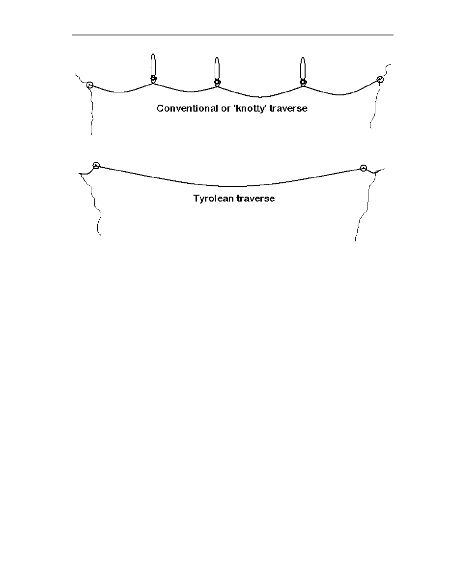
So, we (I) have two general scenarios. A ‘knotty’ traverse where the load passes along a
roughly horizontal rope that is fixed at several points to the walls and therefore must pass
between knots and junctions, or a Tyrolean traverse where the load slides along a single un-
knotted span of rope and has only to avoid becoming a ballistic missile. Both, in practice, are
nightmares to organise OR nightmares to use. You either build something without thinking and
reach brain-failure in the middle of your rescue when everything grinds to a halt, or you plan
and calculate like a boffin and watch things work... or at least fail in a predictable way!
The two prime problems with any traverse are the loads on the rope and the control of the
moving object. Ropes loaded at large angles experience far higher tensions than the simple
weight of the casualty, and it is all too easy to reach a point in a traverse where a section of
rope is taking close to it’s ultimate breaking strain, even with relatively small weights on the
system. Similarly, raising and lowering a load has the advantage of gravity keeping things in
line. A horizontal rescue has gravity trying to prevent movement in either direction! A
seemingly smooth line of horizontal traverses when rigged can turn into a nightmare set of
huge V-shaped valleys and cliffs when you attach cavers to it. Allowing for this and using the
right combinations of extra lines to add teasing little pulls in the right places is the key!
Life on a line
10: Advanced Rigs
123
For cavers using SRT equipment, the knotty traverse is usually easier to pass than a Tyrolean,
partly due to the lack of vertical ‘droop’ under load and partly as more than one caver can
occupy the traverse at one time (subject to them not sharing the same loop of rope). In
contradiction however, a rescue load (an inert object or stretcher) will usually find a Tyrolean
easier and faster to pass, as all of the motion control and tugging can be done from the ends.
Whenever a rescue load has to pass a belay point in the middle of a traverse, you have to get
rescuers out there to manhandle the load, disconnect and reconnect slings and so on. If the
traverse is truly free-hanging with no rock to get a toe-hold on, then even the simple job of
lifting a stretcher by a few centimetres to unload a karabiner can be a Biblical task.
At this point therefore I am going to make two ‘sweeping statements’. I don’t do this very
often, but like buses, they come along in pairs.
Unless the terrain absolutely insists on it, do anything and everything humanly possible to
avoid knots and rebelays in a rescue traverse.
And…
It is easier to make a knot pass your load than your load pass a knot.
(cue confusion)… what I mean (and will explain in the following pages) is that using rebelays
that can be removed and replaced as the load passes through them removes completely the need
to unhook your stretcher, lift any weights, or perform all manner of aerial acrobatics.
But before we embark on the chaos of using traverses, we need to delve into the mathematics of
rigging them. Welcome to vectors 101, there will be a test at the end of the lesson…
Life on a line
10: Advanced Rigs
124
10a1. Vectors, loads and traverses
In Section 5d we touched on the loads experienced by pulleys, where peak forces add
depending on the angles between them. These rules, the mathematics of vectors, govern the
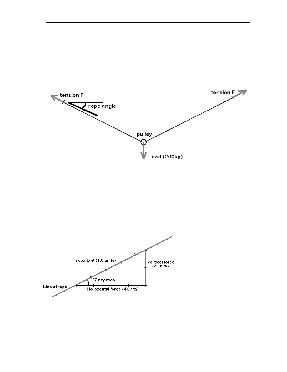
behaviour of traverses too. Whenever you place a load on a section of traverse you are pulling
vertically downwards, yet the load on the anchors is off to the side, creating a Y-shaped set of
forces as shown below. Remember, since rope bends, apart from the weight of the load the
forces acting on the traverse MUST be along the line of the rope.
Newton jotted down that unless things are going to start moving about, the forces in every
direction on a system must equal out to zero. That means that for the forces acting vertically
down (which we’ll take as the weight of the load) somewhere in the system there must be one
or more forces acting vertically upwards that, in total, exactly equal the weight. But in the
diagram the force on each anchor is off to the side! Well, we can think of it as a combination of
two forces… one acting vertically and one horizontally, together adding up to make our off-
angle force along the rope. We can make these forces by drawing a little triangle alongside the
‘real’ force (called in mathematics ‘the resultant’). In the diagram below we see that our little
triangle is 2 units high and 4 units wide, due to the resultant (the rope) being at an angle of
about 27 degrees to the horizontal.
What does this tell us? Well –
in the first diagram above we
said that the sum of the
upward forces equals the
weight of our load. Since the
tension on each end of the
rope is equal (more on this in a
moment!) and the angles are
equal, then we have 2 units of
upward force at each end, total
of 4 units. Let’s say for argument that our load is 200kg – therefore a ‘unit’ is 50kg. Now look
again at our triangle in the second diagram. It says that the vertical load on the anchor is 100kg,
but the horizontal load is 200kg! How about the total – the third side of the triangle? Well, with
Pythagoras you can see it’s given by F
2
= 2
2
+ 4
2
, or the force F = 4.5 units, which is 225 kg.
Remember that if we drag each side of the traverse together you will see that what we really
have is a 2:1 pulley system, so each end of the rope should only see 50% of the load, or 100kg.
Life on a line
10: Advanced Rigs
125
With the traverse stretched out to 30 degrees, the force on each end of the rope has increased by
over 2 times!
This is a common enough example of an angle – a traverse with the ropes at about 30 degrees
below horizontal – and yet the tension on each end is already more than the weight of the load.
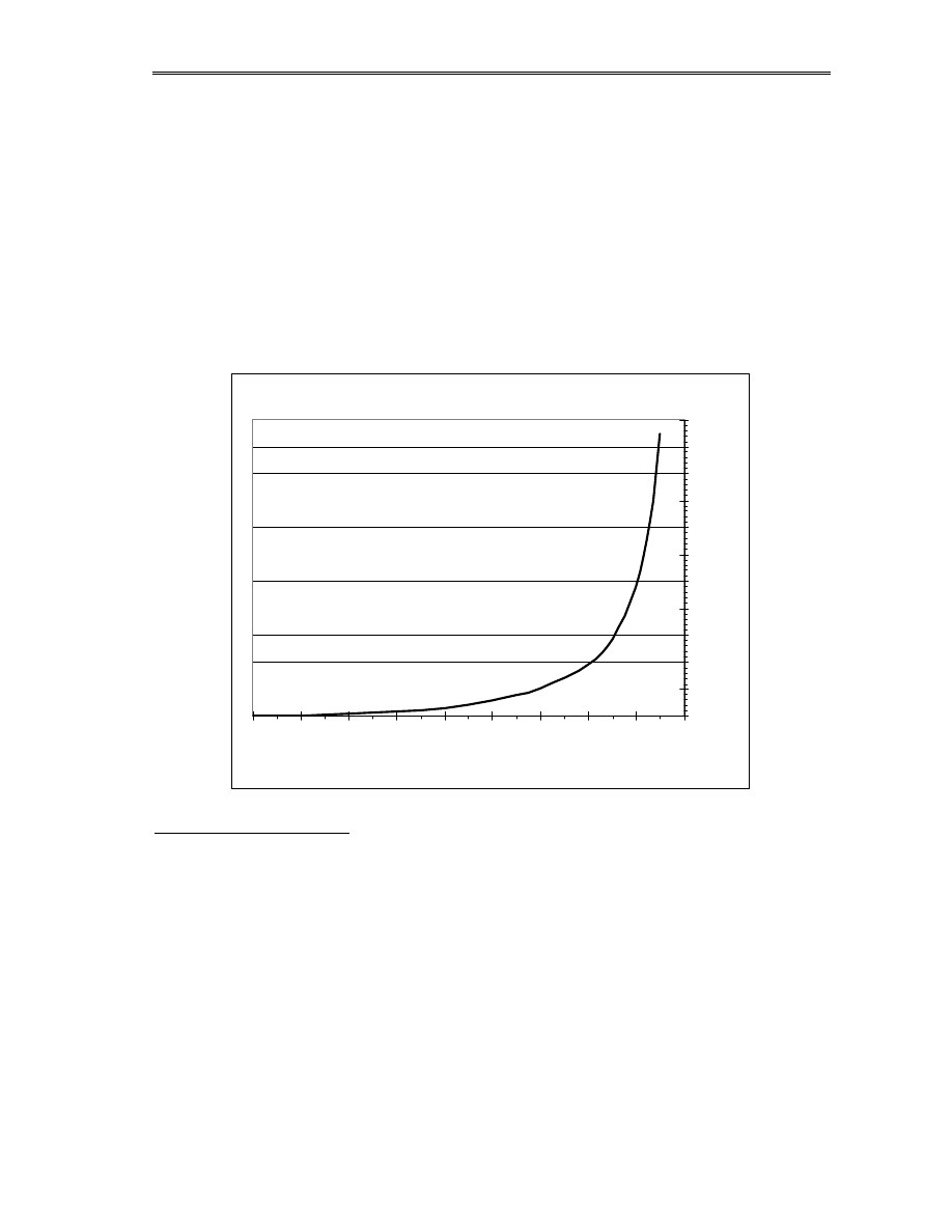
Just by looking at the diagrams above you can see that as the angle gets smaller, the load
increases even more. But the important thing is it doesn’t increase in a nice linear way. To start
with, as the angle moves from 90 degrees (rope vertical) towards zero (rope horizontal) the
tension in the rope only grows slowly. Indeed, by 30 degrees it’s only just over twice the
original. The things get bigger quicker. At 15 degrees the load is 3.8 times bigger. At 10
degrees it’s 5.8, and at 5 degrees it’s 11.5 times the original. In our example above, a 200kg
load would place a tension on our rope of over a ton!
Tension in rope as a function of angle
1
2
3
4
5
6
7
8
9
10
11
12
0
10
20
30
40
50
60
70
80
90
Angle to horizontal (degrees)
Tensi
on factor
Working it out in the field
So you’re rigging a traverse and it’s hanging there… how do you work out the load without a
calculator? Well, it’s not that hard to get an accurate guess, if you can’t remember the graph
above! Start by putting something on the rope so it tensions into a V-shape instead of a curve,
which will show you the end angle at the anchor. Then, against the rock or somewhere suitable,
scrape a vertical line down from the rope and mark off some units. They can be anything – if
you’re working it out for a man load, then make a finger width 10kg and mark off 8. If it’s a
rescue load, then maybe a palm equals 100kg. Anyway, you get a line. Then go horizontally
from the bottom of this line until you hit the rope, and mark that point (muddy fingerprints are
great pencils!). You now have the same load triangle that we used on the previous page – so
you can use your measuring device (finger!) to see the horizontal and resultant (along the rope)
forces just by measuring the triangle’s sides!

Life on a line
10: Advanced Rigs
126
Remember that under load even static rope stretches, as a result the true angles will be larger
than you get from clipping a tackle bag to the rope. But as we know now, larger angles mean
less extra force, so if you’re safe with your muddy-finger triangle then you’ll be safe with your
full load. The only exception to this is using wire cables, where stretch isn’t a factor. With wire,
angles must be calculated very carefully as it is possible to achieve very small angles if you
don’t allow slack, and this can of course lead to massive tensions in the anchors!
NOTE: For Tyroleans with a small angle of deflection then several publications give a shortcut
formula that is roughly accurate without using Pythagoras... if the ‘sag’ is the vertical
deflection of the rope when loaded and the ‘span’ is the straight-line distance between the
anchor points, then:
Sag
Span
Load
Tension
*
4
*
=
This works reasonably until the sag becomes more than 25% of the span.
10a2. Rigging traverses
I am not about to tell you how to rig anchors (we’ve done that) or how to rig a knotty traverse
(that’s basic SRT). Few cavers use Tyroleans though, and fewer still have the issues of safety
and redundancy to deal with.
Let us say that we have a deep water-filled cavern to pass using a Tyrolean (Harrison Ford
moment….) and that the issue of getting a rope from one side to the other has been solved, you
have sufficiently huge anchors at each end to take the loads and that you must send over a
stretcher and medic. The initial checkpoints are:
1) are the anchors high enough and back from the edges enough to let us load and unload
the stretcher easily?
2) Given a safe angle to the traverse of say 20 degrees, will they drown in the middle?
3) Is the end point higher than the start or the other way round?
1) is a matter of rigging and by now should be second-nature to your rescue brain. 2) may
demand that you put some intermediate rebelay in place, and 3) decides if the team at each end
are pulling or letting out. Remember that to pull a stretcher uphill, especially the last few
metres, requires a lot more effort than to let out lines from a descender, so share your men
accordingly, even consider Z-rigs or suchlike.
Now the components of the traverse itself. You should have guessed these by now even if
you’ve never seen a Tyrolean!
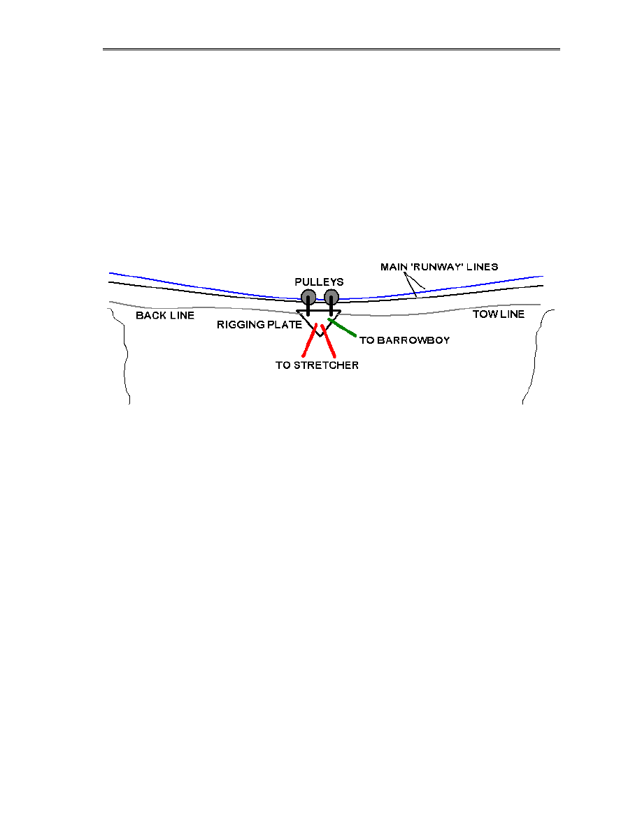
1) A
pair of tensioned lines acting as the runway for the traverse. Yes, a pair, as we are in
rescue mode – so we need a backup don’t we! These lines are called ‘runway lines’ in
this book.
2) A tow line (or front line) from the load to the destination so the team can pull it across
3) Another tow line (called a back line) from the load to the origin, so the team can both
let out the load in a controlled manner and pull it back if something goes wrong
Life on a line
10: Advanced Rigs
127
4) Optional – a single independent runway line as a backup for the medic or barrow-boy,
to conform to our safety rules as there are two people on the system.
Our stretcher is to be connected to the runway lines using two pulleys, ideally that span both
lines (using a big pulley such as the Petzl Kootenay) otherwise you will hit problems if the
runway lines get twisted. The medic will hang on these pulleys too, and optionally be
connected to a single pulley on his independent backup line. Please note, and this is important:
If your medic is connected to his own backup line he must NOT be connected to the stretcher
directly. Should the stretcher connections fail then his backup line may not support the
combined load of him AND the stretcher. The medic should also carry in his SRT kit a spare
pulley or two, so that in dire cases he can travel along the traverse independent of the casualty.
The origin party, who lower the stretcher out from their end, initially controls the motion along
the traverse. Until it reaches close to mid-way between the ends the load will be trying to rush
ahead and so must be lowered out. Once it passes the midpoint, the destination party have to
haul in. Both ends must remain controlled however, if for no other reason than recovering the
pulley blocks back to the start for the next trip!
The actual use of a Tyrolean traverse as shown in the above diagram is relatively simple, but
takes effort. There is always a compromise between having very taut runway lines (and hence
little sag but high anchor loads) and slacker runway lines, making the sag greater but putting
less stress on your gear. The exact level of sag is a matter of experience and judgement, based
on the calculations we have discussed a few pages back.
As with all hauling systems, the complex stuff is when you are loading and unloading the
stretcher at each end. Careful pre-planning is essential to make sure that the runway lines are
high enough to enable the load to arrive safely, and that there is enough distance before the
pulleys hit the anchors so that the stretcher can be unloaded a safe distance from the edge.
Underground you may not have the luxury of high anchors, and so you will often have to resort
to using the tow and back lines to physically haul the stretcher off and on the traverse.
Life on a line
10: Advanced Rigs
128
The effort involved in tensioning the lines and hauling the pulleys
in the last few metres must not be overlooked – you will almost
certainly need a mechanical advantage system of some form to do
this safely. However, you must resist the temptation to use a
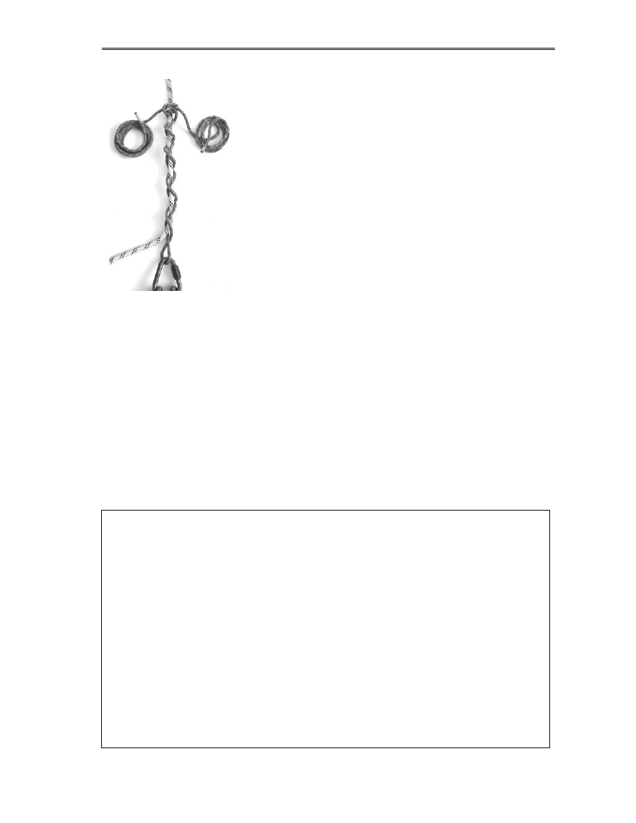
simple Z-rig to tension your runway lines. When locked off, a Z-
rig holds the rope using an ascender, and given the fact that our
runway lines are known to be taking a very large tension, gripping
the rope using a toothed cam is asking for trouble. It is far safer to
use a friction system such as the Dog and Tails knot to hold the
runway lines, with a Z-rig behind the Dog and Tails to haul in the
rope, but which is released slightly when the runway lines are set,
so that the anchor forces are transferred through this friction knot
instead. To release the runway lines the Z-rig can be re-tensioned
to loosen the Dog and Tails before removal. Also, similar logic
should apply to the far end of the runway lines – it is stronger to
secure these using a Dog and Tails system in front of the final
knots than just knot them directly.
For a long traverse (not common in the UK but possible elsewhere) then there are several
purpose-designed tensioning devices for runway lines, usually relying on a winching action.
A Tyrolean can be the basis of several more complex rigs with only minor changes. It is a very
useful base technique to learn, and agreement in advance on the way your team will use
traverses saves a great deal of ‘discussion’ on the pitch! Above all, the following rules should
apply:
1. Only one rigger decides on the design details. It must be agreed in advance if
communication between the endpoints is difficult.
2. During the transit of the stretcher, the barrow boy calls the shots.
When training, remember not to leave a set of runway lines under tension for prolonged
periods, as it stresses the rope. If you are taking a lunchbreak, loosen the lines!
Steel cable traverses
For very long spans or fixed traverses, a lot of industrial teams will use steel cables. They
have the advantage of lower physical size and far less stretch (and hence sag) but their use
must be implemented with care.
Firstly, the cable must be rated to support the tensions involved. Steel wire cables usually
have a breaking strain of 180kgF per mm
2
. Secondly, fixing the cable is often a major point
of weakness. Steel cables are usually finished in a swaged eyelet, and any anchors rely on
this one point of attachment, as it is difficult to secure any further devices to the cable.
Tensioning the cable requires either a cable made to exactly the right length or a winch to
draw in the excess securely, since ropework systems such as the Z-rig do not apply to steel
cable.
In particular, never be tempted to use winching systems not rated for live loads (such as the
common Tirfor cable puller). They may be strong, but they are also prone to failure in
nastily fatal ways!

Life on a line
10: Advanced Rigs
129
ASIDE: Fixing the stretcher
There are two basic methods of securing the stretcher to the traveller pulleys, assuming that you
are keeping it horizontal. In all but a few cases you will be, and if you are not then the method
is fixing is pretty self-explanatory!
The first option is to hang the stretcher like a bag of groceries (called a centre hang) using long
ropes from each end of the stretcher to a single set of pulleys. A safety line to the patient can
also be fitted as shown, or they can be linked to the stretcher itself. The second option is to end-
hang the stretcher using two spaced pulleys and shorter ropes. A linking rope (in blue) ties the
pulleys together so that the towing action on one pulls the other along in unison.
Which you use is not just a matter of preference. For a Tyrolean or a long-span traverse then
the centre hang is essential, as an end-hung stretcher will tilt to match the angle of the runway
lines. In a Tyrolean, these runway lines are often at an alarmingly steep angle at each end, so
the casualty is in danger of being held head-up at one end and head-down at the other!
The disadvantage of the centre hang is that it is impossible to cope with rebelays. Knot-passing
pulleys can be used to pass knots in free-air, but passing an anchor is plain old not going to
happen, since you cannot release the load on the traveller pulleys one-at-a-time. This is where
the end-hung stretcher is the only option… and leads us nicely on to:
10a3. Knotty traverses
As we have said, a ‘knotty’ traverse is one where there is one or more mid-span rebelays in the
runway lines. For a single caver, a knotty traverse is often easier to negotiate, but for a stretcher
it is both slower and potentially more dangerous. The major difference is the presence of people
– to get a stretcher past any mid-span anchor you will need team members out there to clip and
unclip things, lift and pull and push as required. They have to be supported by some means and
must be numerous enough to do the job but not get in the way of progress. In a tight knotty
traverse (such as the infamous Battleaxe) then the presence of these helpers can make the entire
enterprise a logistical nightmare.
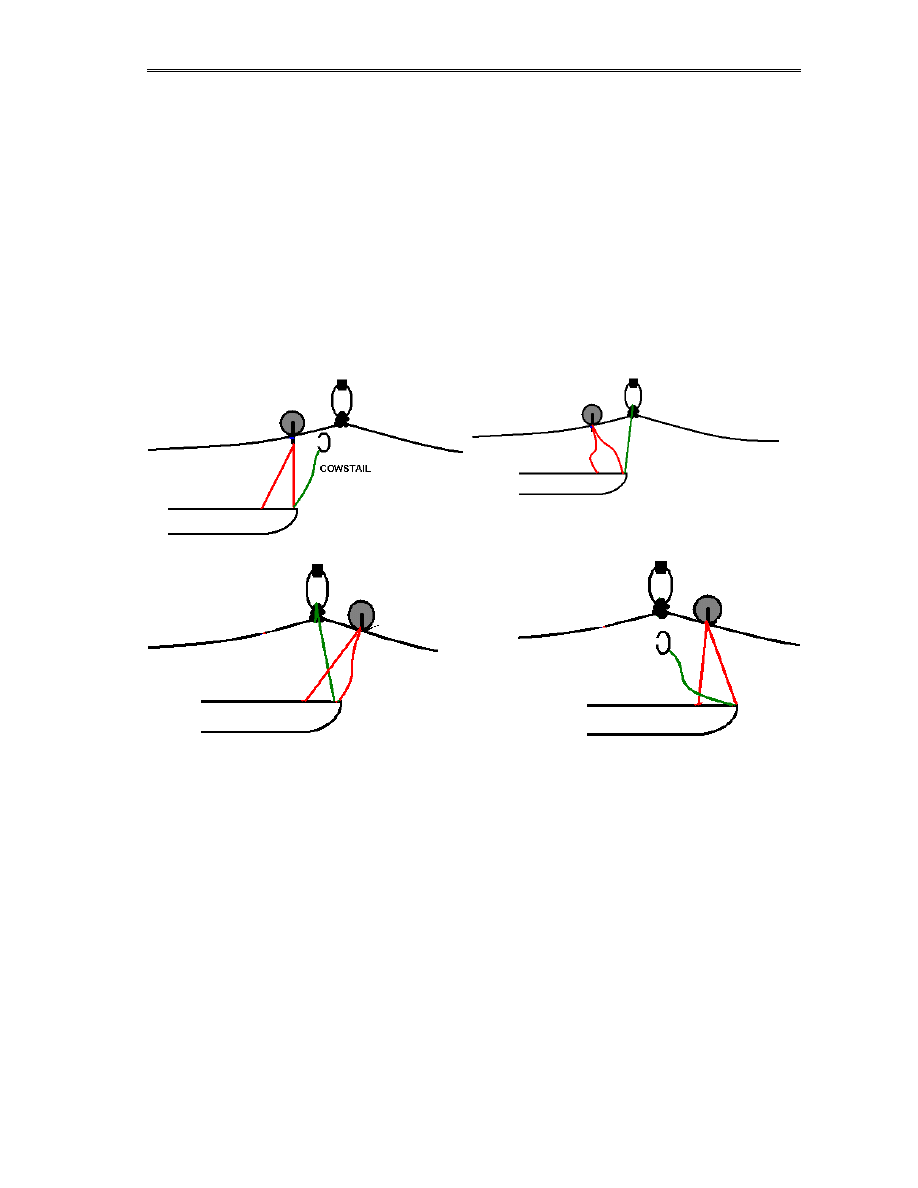
The basic premise (and calling it basic does nothing to make it simple) is to use an end-hung
stretcher and to pass each end over each rebelay as it moves, exactly mirroring the way a caver
crossing a knotty traverse uses his two cowstails to pass knots. At any one time at least one

Life on a line
10: Advanced Rigs
130
pulley is secure on the traverse, so calamitous failure of the passing-over operation will not
cause total loss of the casualty. Doing this in practice is the sort of job you can only manage by
lots of practice and lots of liberal application of rude words. Moving a stretcher on a knotty
traverse has been likened (and very accurately too!) to watching ants transport leaves: from a
distance the leaf flows over obstacles, but up close there are ants hanging on all over the place
passing things about like the world is about to end.
If I said here ‘neglecting the issue of rigging the traverse….’ Then a lot of you would just
accept that and read on – however, it’s far from obvious how to do this in reality. You’re
rigging for rescue now – so we need two of everything. Two lines in parallel are an option, but
then they’ll share the mid-span anchors, and will it make the passovers more or less complex?
Do you know? (do you care…)
In reality, for a knotty traverse there are two options and a cheat. ( as always! ).
1. Rig another knotty or Tyrolean traverse some distance ABOVE the loadbearing one,
and use long safety lines to fix the stretcher to this backup system
2. Rig parallel lines on the traverse and let them share mid-span anchors if needed, but
have independent end-point anchors.
Option 2 is only realistic when option 1 is not possible, since it increases the confusing mass of
ropes for the team to handle. A higher-level backup traverse can be controlled by a single man
moving along it and transferring the safety line over, provided that he does not unclip it when
either end of the main traverse is removed, the backup rule is relatively unbroken. The anchor
points for the high-level traverse may also be useful to support your team members at the
passover points, since they cannot use the same anchors as the stretcher.
And the cheat – rig your traverse using steel cables and high-strength anchors, then trust it. This
is not an option for impromptu rescue, but has been pre-fitted to common routes, such as the
famous rescue traverse in Kingsdale master cave stream passage.
We will assume from here on that we’re using a high-level backup of some form, and deal with
the logistics of moving on the main traverse only.
One final point that will become clear in a second… when you are tying off your mid-span
rebelays, make sure that it is possible to clip a karabiner directly into the anchor, or into the
loop of rope from the anchor to the knot. If you use maillons to connect a butterfly knot to a
hanger, then you may like to change them to karabiners for this exercise to give a nice open
clipping-point.
Unless a span on our traverse is long, I suggest that using tow and back lines is not usually
worthwhile. Having a short line coiled on the stretcher to use if need arises is fine, but it’s far
easier to physically move the stretcher between hands where that is possible. You are going to
encounter issues with the stretcher tilting, since it is fixed from both ends, but that is a price to
pay. It is possible to engineer adjustable ropes on the stretcher to compensate for the tilt if you
really need to (if the medical condition of the casualty requires it), but in normal cases that adds
time and complexity to the rigging with little benefit. So, the stretcher moves out onto the rope
and is pushed and pulled up to the first rebelay, where we have one or more team members
positioned from miraculously-placed anchors (or the high-level traverse).
Life on a line
10: Advanced Rigs
131
The end of the stretcher arrives close to the knot, and you must support it while you physically
unclip the pulley, move it past the knot and reattach it. To do this, a short length of rope from
the end of the stretcher, a few inches SHORTER than the ones going to the pulley, is used. If
you have team members about, then it is physically not that hard to lift one end of the stretcher
a few inches up while this ‘cowstail’ is clipped directly into the anchor. Now you see why we
needed to make that clipping-in easy when we tied the knots! The pulley will then be just slack
enough to let the rigger swap it over, then another quick lift and the cowstail can be removed,
leaving the stretcher to move on. The same then happens at the back end using another
cowstail.
One little hint – make sure the riggers out in mid-air have a few spare pulleys clipped to their
harnesses. With many designs of pulley to remove it from the rope involves removing it from
everything, and it is wonderfully easy to drop at that point!
The four diagrams above show the sequence in action – without the people and confusion
normally found underground when trying to run this type of traverse! Based on this, you can
see that a knotty traverse without footholds is to be avoided at all costs, since lifting the end of
the stretcher by hand really needs a team member with a foothold to push against. If you have
not got the luxury of footholds, or you can only have one man operating on the traverse, then
you need to be able to load and unload the cowstail without needing a free hand to deal with the
stretcher too. In that case, a simple adjustable cowstail (using a Grigri or a descender as a
releasable hauling device) will work much better. Putting the Grigri at the top of the cowstail
allows the team member to use his weight and a 2:1 advantage to lift the stretcher, even if he
has no secure foothold to lift from normally. It is of course vital to use a device that can be
released under load – a pulley/jammer combination would be impossible!
However, sometimes tortuous winding rifts and knotty traverses are not your problem –
equally fun to deal with is a deep open gorge with overhanging edges and a casualty at the
bottom!
Life on a line
10: Advanced Rigs
132
Cue…
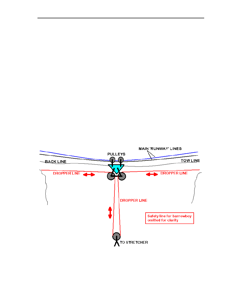
10a4. Crane Jib traverses
This technique, used to great effect for these restricted access gorge rescues, is so named after
the way it behaves like the jib of a tower crane. A Tyrolean traverse is used to span the gorge,
but from the traveller pulley block a vertical system of ropes is used to raise and lower the
casualty/rescuer from the middle of the runway. Although complex to rig, the crane jib traverse
offers unlimited movement in a rectangular plane under the traverse, allowing it to reach
anywhere, even with trees or cliffs blocking the route for a simpler V-rig (Section 8b).
The basis for this system is a full rescue Tyrolean as we have described above, giving us a
‘traveller’ pulley block moving over a pair of runway lines, and held from each bank by tow
and back lines. Then comes the clever bit. A new rope is rigged across the gorge, but routed
through two new pulleys clipped into the traveller. The centre of this rope therefore hangs in a
vertical loop below the traveller, and a pulley on this makes us our raising/lowering system.
Paying out or pulling in this new rope from either bank moves the casualty vertically and
independent of the position of the traveller. We will call this new rope the ‘dropper’ for want of
a better name. Yes, I am making all of these terms up as I go along, and no, nobody else seems
to have found a better set and published them!
To use it therefore, in essence, the traveller is sent out to the right place and the tow/back lines
tied off securely, locking the traveller in place. The dropper is then paid out, the casualty
connected and the dropper pulled in. Once raised, the dropper is secured and the traveller
moved again to bring the casualty to the bank.

Life on a line
10: Advanced Rigs
133
But what happens when the traveller moves? Surely the casualty goes up and down? Well no.
That is why the dropper runs from BOTH BANKS. The vertical position of the load is set by
the total length of the dropper between each anchor, not the position of the pulleys and bends,
so as the traveller is moved the dropper slips past the pulleys and to a reasonable extent the
casualty stays put!
For a real system, practice has shown that a single SRT line, fixed to the traveller and used by
the medic ‘conventionally’ is better than letting him/her ride on the dropper on the way out. It’s
an issue of confidence, but the medic is often happier being self-propelled. You can satisfy
your redundancy issues by either using another dropper in parallel (which gets very complex if
you don’t practice this system a lot!) or running an ascender on a free-hanging backup line
from the traveller. Since the traveller is connected to the banks by 4 ropes, it can be taken as
‘safe’!
Also, in a real system there will be some vertical movement of the load as the traveller slides,
due to the stretch in the runway lines and the dropper. However, as your load is on a nice 2:1
pulley system, it is quite simple to adjust the vertical position as you go. On occasion I have
used an exercise to practice this, by spanning a lake and making the team send a stretcher
across the surface without getting it wet, but without letting it rise more than a foot above the
water. Not exactly walking on hot coals, but just as fun if you dare to put someone in the
stretcher while they practice!
Aside: failures on traverses
I have seen the crane jib system rigged where the dropper only extends to one bank. It’s either
tied off at the traveller or starts and ends on the same bank, and pulls against the front line
when in use. This is potentially highly dangerous. The front line receives high loadings from
the pulley systems, and if it fails the load will whistle down and back to the foot of the bank
with nothing to stop it. Cue thoughts of champagne and ships… If the dropper spans from both
sides, then even a snapped tow line shouldn’t cause chaos. At most, the traveller will drift back
to the centre of the traverse to await recovery.
Recovery of a traveller if either the tow or back lines break is in theory simple – you pull it
back using whichever line is intact, and try again. Breakage of one of the runway lines may
drop your casualty a few feet due to stretch, but is not catastrophic. The only major problem
that could arise is if the traveller physically jams on the runway lines, maybe by winding up on
a bit of loose rope, when the medic/barrowboy come into his own by being able to climb up to
the traveller and cut things free. Pulleys rarely fail in the sense of stopping turning, and the
friction involved is such that even if they did, the teams on each bank could still propel the
traveller without problem. Once you have both a tow line and back line, the old James Bond
scene of being trapped in mid-span is extremely hard to achieve in reality!
Traverses remain probably the most complex rigs used in underground rescue (going by the
number of ropes and pulleys involved) and from experience of watching teams, especially from
non-caving backgrounds, it is clear that without specific practice things can rapidly turn into
chaos. More often than not during a traverse of any form, there will be times when some of the
team are out of communication with the rest but still actively doing something, and pre-
planning is vital to stop two groups pulling on the same rope and wondering what’s jammed.
Life on a line
10: Advanced Rigs
134
10b. Combination pitches
The combination pitch is the nemesis of any rescue rigger. Putting it simply, it’s a pitch where
a traverse leads out to the start of a vertical ascent or descent, and the point of changeover has
no sensible access.
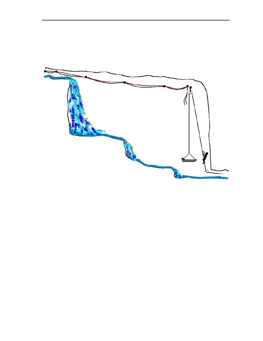
In the above (terribly non-artistic) diagram a counterbalance bottom-haul is being used to raise
a stretcher to the end of a long knotty traverse, trying to avoid a nasty moist cascade.
After reading all about hauling and belaying systems, and now traverses, in theory you are now
armed with all the knowledge you will need to arrange a combination pitch. What you will
rapidly find when trying it however is that the tiny things grow to bite you. All of your hauling
rigs are designed to be easy to construct and operate provided you have ‘local access’ to the
equipment – in a combination pitch your hauling system may have to be many metres away
from the pitch itself, and yet somehow the stretcher must be transferred off and on seamlessly.
In the above scenario you should be thinking of the many other ways to achieve the aim, and
the merits and pitfalls of each. Why not use a Tyrolean instead of lots of knots? Could we haul
from the top of the cascade or is the horizontal path of the rope a problem? How about using a
V-rig with controlling lines to raise the stretcher diagonally? Could we do something with
releasable deviations? How about just going to the pub?
As a rigger, you should be thinking of all the options as you see a scenario, and going with your
judgement. You may find what you planned to do won’t work (lack of kit, cave that hates you,
etc etc), or you may find the rules change mid-rescue (casualty arrives in a stretcher instead of
walking-wounded, someone turns on the rain outside, etc etc). You must adapt without being
fickle, and keep a calm overview in your head no matter how much that last option above
seems to be the best!

Life on a line
10: Advanced Rigs
135
10c. High-ratio pulley systems
This section lives somewhat separate to the other pulley-based chapters, as we are dealing here
with the specific use of multiple-pulley combinations to gain high levels of mechanical
advantage. A Z-rig or V-rig only multiplies the applied force by 2 or 3 times, but it is relatively
easy using a handful of pulleys to rig a system that has a factor of many 10’s. This has quite
rare applications underground, especially in the UK, and so it is why I’ve hidden it away here.
The problems are clear – you have to pull an absurdly large amount of rope through the device
to gain a short distance on the load side, and the tensions that you can apply to the load and
associated equipment can be huge.
Over the years in underground and industrial rescue I have yet to see more than a handful of
applications where a pulley factor of more than 3 is required (satisfied by our humble Z-rig).
Lifting a load of more than 300kg is rare, and a two-man team can adequately shift such loads
using a 3:1 system. Applications where long arduous hauls are required are almost always
better satisfied with a lesser-ratio system such as a Z-rig plus changes of shift on the hauling
party, or ideally a winching device. The length of rope required for a large-ratio pulley system
grows dramatically, and so the maximum extended length of these systems is often limited by
rope to quite short sizes.
High-ratio systems do have a place in digging work though, by which I mean the movement of
large boulders and so forth. If you have to move a massive rock a few inches in order to free
someone, then a high-ratio pulley system comes into it’s own. As the distances of rope pull are
also in ratio, it is easy for a hauling team using a high-ratio pulley to control the position of a
load to a high degree of precision. Provided that protection is being used to deal with a rope
failure (using wooden blocks, props etc) then there is no real risk.
Calculating the load in the rope of these systems is vital, and so is the choice of components.
You can easily apply several tonnes of force to the endpoints, and anchors, karabiners, pulley
sheaves and rigging plates must be capable of taking the expected load. The problem is that
when pulling through a 10:1 system, there is less of an intuitive ‘feel’ for the weight, so the
rigger must work predictively. Clearly the best guess of the ultimate forces is the object being
shifted – if you are trying to lift a boulder that you estimate weighs 500kg, then that is the force
you have to account for. The other option is to work from the force your hauling team can
apply, though this is a great deal more vague. We hinted in our opening sections that an
average team member could haul (when standing) about 400N (equivalent to a 40kg load on a
1:1 ratio system). If your pulley blocks impart a 10:1 ratio, then each man can roughly impart
4kN to the endpoints, therefore lifting a 400kg load.
As you can see, even with one man, the forces on the endpoints rapidly start to creep into the
figures for breaking strength of karabiners, belay plates and slings.
So how do you know the ratio of your system? You clip a bunch of pulleys to an anchor,
another bunch to the load and thread the rope back and forth like a cat’s-cradle, then what?
Well, the rule is that the number of ropes in between the pulleys gives the ratio. So, if you
count six ropes passing back and forth between the endpoints (for which you’d need 5 pulley
sheaves) then it makes a 6:1 device. If you look back at the earlier sections on V-rigs and Z-rigs
you’ll see it works there too… a V-rig has three active ropes in between the pulleys.
Life on a line
10: Advanced Rigs
136
Simple logic therefore says from your ratio you can predict everything about the rigging… say
you want a 10:1 system and have a 200m rope. We know that to get 10:1 you need 10 passes of
rope between the pulleys, so we know the maximum length of this creation is a little under
20m, and you’re going to need 9 pulleys in total. You also know that to lift a 300kg load by 1
metre, you need to pull 10 metres of rope through the rig, and that one man will happily be able
to do this.
One final bit before talking safety… if you are rigging a pulley system in a muddy place, as
you may well decide you wish to do, then as the ratio increases so the effort required to draw
the system back out to length also increases. It takes a heck of a lot of effort to pull a 10:1 ratio
system back out when the ropes and pulley sheaves are clagged in clay, so if resetting the
system is going to be needed then plan how easy it will be. Never assume a dangling tackle bag
will do the trick, a tail rope to a heavy-set individual with big arms is probably more in order.
The safety bit
Clearly you can go to town on ratios and make a system that will lift a small town, but you will
rapidly find that karabiners are not made for this designated purpose. If your pulley system has
a ratio large enough to risk overloading the components within it, then you must assume that it
will fail. This is not pessimism, just common sense – in the heat of the moment with your
shoring crew shouting for more lift, your hauling party cannot measure their arm strength and
point out you’re nearing the SWL of rigging plate 4. You therefore should allow for failure by
making sure the load is controlled. If the load falling would be bad, then stop it happening
using backup lines, wooden props, etc as it’s lifted. If it can fall safely and you want to let it
drop, then you still need to think about the pulley system itself. If an anchor fails, the tension in
the lines will make the remainder of the system fly about like a snake on Viagra, so you may
wish to think about protecting your team from incoming aluminium.
10d. Winching and powered aids
For industrial high-angle rescue on buildings, towers and in shafts,
the notion of using a mechanical powered winch is almost universal.
No self-respecting industrial rescue team would be seen without one
or more of the commercial rope hoists, electric winches or capstans,
and their use is increasingly looking an option to underground teams.
Winches are not a catch-all device. They are a Godsend for long
pitches, surface shafts and so forth, but deep underground the classic
ropework of Z-rigs and belays works far better. UK teams are also
unlikely to have 10 shiny winches in their kits, but a lot of rope and
pulleys!
The usual arguments against using winches are cost, proprietary
equipment and the ability to cope with the conditions underground.
Clearly a mains electric winch isn’t an option at the foot of a complex
Dales pot, but there’s no reason why it can’t be used for the surface shaft. Broadly therefore (at
the risk of annoying manufacturers worldwide) I’m going to say that:
Sked Uni-Hoist
Life on a line
10: Advanced Rigs
137
Powered winches are only suitable for surface-linked use
There will be nice exceptions where the power isn’t a problem, but you can’t rely on that. I
prefer the notion that your entire rescue kit will function after being taken through a 50ft sump
and will continue to function after being dried carefully in a sandbank. The options for true
underground winches are limited therefore to hand-operated devices, which is actually not that
limiting at all! The market is filled with rescue winches ‘with a handle’ and the team is left only
with the issues of compatibility and pricing.
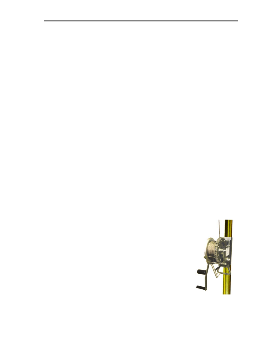
Two vital decisions on the choice of a winch are the rope capacity and ease of reset. Winches
fall into two categories for live-load certified products, capstan and reeled designs. A reeled
winch has a fixed length of rope or wire fitted to an axis, and it pays out and takes in this rope
by spinning the axis. Examples include the Sked Uni-Hoist as shown above, which uses
stainless steel wire cable and is available in a range of fixed lengths from 70ft to 300ft. Yes,
you guessed it, the 300ft winch is pretty damn heavy! Also, the Uni-Hoist is only live rated to
160kg, which means it’s below our limits for rescue loads. It was designed to lift either a single
casualty or a single rescuer, and so should NOT be used to lift double loads. Underground
rescue can make these reeled winches far less of a viable option than surface high-angle work
(where they predominate), as the confined spaces and limits on cable length mean a winch is
often more trouble than it’s worth. In addition, reeled winches are more complex to clean – the
cable has to be unrolled and washed after every ‘dirty’ rescue.
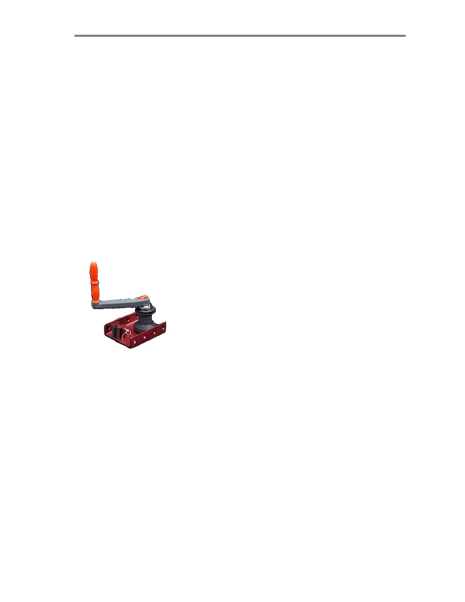
Capstan winches on the other hand take any length of rope. It
is wrapped one or more times around a capstan, secured using
various combinations of clamps, and the rotation of the
capstan draws in the rope. The advantage of capstan winches
is that the length is only limited by how much you can carry –
the winch does not care. The disadvantage is that they rely on
friction (reeled winches are in essence locked to the rope and
friction is irrelevant) and so wet and muddy ropes can slip.
Safety devices will prevent the load from falling, but raising it
may be another matter entirely!
The BMS Ropehauler shown here is one of the more common
capstan winches rated for live loads. It is rated to 275kg SWL and has a 12:1 gear ratio.
Although securing this little beast can be fun (the 8 mounting holes in the baseplate for
securing the winch to anchors are great, but to turn the handle the winch needs to be SECURE
and not just tied to the wall!) it’s light (6kg) and will work with any length and diameter of
rope, except metal cables.
Note that the BMS has no active rope clamp, so an external device must be used.
Note 1: Man-rating or live load rating
There are literally hundreds of commercially-available winches on the market, from automotive
recovery winches to sailing and building winches. However, in order to use a winch of any
design for lifting humans, they MUST be certified for ‘live load’ or ‘man rating’, which means
that their quality control and methods of failure are approved and safe. Under current
legislation (as discussed later in this book) a rescue team may not use any winching or hauling
device that is not certified and maintained according to the live load specifications. Devices
BMS Ropehauler

Life on a line
10: Advanced Rigs
138
intended for inanimate loads (such as are used on sailing boats) may visually look the same as
rescue devices, but are not designed to fail in a safe way and are not guaranteed to the same
level of minimum failure load.
There are also many industrial fall arrest devices, which look on first inspection to be similar to
winches, except that they tend to have a self-retracting spring system inside them to keep the
cable under tension between the winch and the load. They are specifically designed for
preventing falls on industrial sites and are NOT rated for use as winches. The legal certification
of ‘fall arrest’ and ‘winching’ equipment is different and to use a fall arrest system as a winch
is illegal. Many fall arrest systems, if you read the small print, must be stripped down or
replaced after every full loading.
Note 2: Wire and rope and bits of string
A winch, be it a capstan or a reeled type, is usually only designed to work with a specific type
of rope or cable. Winches such as the Uni-Hoist for example use steel cable, while the BMS
Ropehauler works only with rope. It is often physically possible to use a reeled winch with the
wrong type of line, but the performance is badly affected. However, capstan winches designed
for use with synthetic ropes are unsuitable for metal cables full stop. A capstan winch relies on
friction between the few turns of line and the surface of the capstan, and wire cable in essence
has no friction. So…
Never use wire cable in a capstan winch. Never. Ever. Ok?
10d2. Home-made winches
After all the waffle above about legal certification, you can guess that making your own winch
is a tricky affair. Having said that, in the UK a lot of rescue teams and caving clubs have large-
scale surface winches (often the sort of beast it takes 6 men to carry) that are powered by
electric or petrol engines and used to haul caving parties in large surface shafts. The famous
winch used at Gaping Gill is the best-known example, but almost all caving areas have
someone who’s shed houses a prized beastie.
The legal status of these types of winch is questionable to say the least. When used by a caving
club and no charge or public access is permitted, then the certification and rating of the winch
is reasonably irrelevant, as the users are accepting a presented known risk with prior
understanding. In a rescue however, you may be lifting people (the casualty for one, and maybe
medical personnel as well) who are not covered by the ‘club membership’ exemptions. Teams
can therefore be in a sticky situation – clearly if a winch is sitting there and will greatly reduce
the time of the rescue then it is in the casualty’s medical interests to use it, and the risks from
the winch outweigh the risks from prolonging their time to hospital. However, the team could
find themselves liable if the winch upped and died mid-rescue and bounced someone off the
floor. Team riggers therefore must take whatever precautions they can to ensure that the winch
is NOT the ‘primary supporting equipment’. That means that the person being lifted or lowered
may be physically moved by the strength of the winch pulling on a rope, but their main
protection against death is from a second certified rope. The simplest example is that a load
being lifted should be secured to another one or two lines using running ascenders. On a
descent, the same can be achieved using conventional belaying from above.

Life on a line
10: Advanced Rigs
139
Hopefully at this point you have all the
techniques you will need for
underground rope rescue. Applying
them is the skill, and adapting and
combining the individual systems of this
book to achieve your aims. Remember, your goal as a team rigger is to convey the team down,
the casualty to the surface and the team back out, all safely, rapidly and with allowance for
problems on route. The most textbook-perfect system is no good in a cave that hasn’t had the
good courtesy to read the same book!
As with all emergency work, from cave rescue to A+E medicine to police drivers, the
indication of an expert is someone who can deal with an ever-changing situation with calm,
efficient progress. Panic, arguments, fiddling and discussing are fine in practices and debriefs,
but on the day, you have a job to do and the lives of everyone around you depend on your
abilities to apply the skills you have learnt. Do not make them wonder if you’re up to it.
Cave Rescue in the UK is not run by a bunch of amateurs.
We just don’t get paid.
We now delve into the associated areas of ropework, the law, care and handling, and training.
Cave rescue in the UK is a volunteer service and as such relies on the expertise of the members,
not only in performing the rescues but also in training and running the teams. You can’t escape
paperwork by going down a hole!

Life on a line
11: EN Marking, PPE & the law
140
11. EN marking, PPE and the law
Cave rescue teams, and other ‘professional care’ teams using these techniques
within the UK and EU are required to comply with the Personal Protective
Equipment directives. There are some exceptions to the normal working health
and safety regulations for rescue teams, however the fact that team members are volunteers
does surprisingly little to change the legal standing of teams and the equipment and procedures
they can and cannot use. At the time of writing there is still however a big question-mark over
the use of equipment by rescue teams, which is one of the reasons this section of the book was
delayed. Unfortunately, nothing much has changed despite the wait, so what we present here is
likely to be wrong pretty soon. Rest assured that as and when things are clarified we will update
the chapter!
If you are working industrially with ropes (rope access, construction, etc) then you have a rigid
set of regulations to comply to. Overall, the Health and Safety at Work Act 1974 (HSAW)
controls the equipment, procedures and documentation required to conduct any work-related
task where there is a risk of injury. It is an ‘enabling act’, in that it calls on specific regulations
to actually define the law. For confined spaces, that is the Confined Spaces Regulations 1997,
for chemicals it’s COSHH and so on. These regulations define the approval and marking of
equipment and so the ‘do I need a CE-marked widget and what EN standard does it comply
to?’ question is encompassed in this structure. If a rescue team is operating as a professional
body (for example as part of the terms of employment, as some Fire Service and military teams
do), then they are bound by HSAW and have to comply with it in all its details. Volunteer
teams do
not have to comply to HSAW as they are not ‘at work’, but there is, as always, a
pitfall.
Suppose you’re on a rescue, and you’re all working away happily. You’re all volunteers and so
while you give a courteous nod to the rules, you do what works and what you’re all used to.
Then you find you have to call in help – be it anyone from the medical profession to a team of
50 army types with shovels. Instantly, you now have people using your gear that ARE covered
by HSAW, and you’re proverbially stuffed. The response is usually “ahh.. but if they agree to
volunteer then it’s ok”. Sorry, but that’s not strictly true. An employee at his job of work cannot
exempt himself from HSAW even if he wants to. If he isn’t legally allowed to descend a shaft
on non-certified equipment then that’s the way it stays, even if he signs your left arm with
badger blood.
However, if you are working in
rescue, the legislation gets horribly messy. In an effort to
prevent misuse of equipment AND to ensure that existing techniques weren’t instantly
outlawed, the legislation exempts some parts of itself if rescue is the goal of the exercise. It is
not important to these exemptions if the people doing the rescue are professionals or
volunteers, it’s the fact that it’s rescue that makes the difference. This is crucially important for
rescue teams, as it applies to anyone – so your army shovellers are equally exempt even if they
are ‘at work’ while rescuing. It’s not a blanket exemption from everything, but it does have
some useful sidesteps for the use and certification of equipment.
Before I try and wade through these exemptions, let me walk you through the chaos that is the
EN/PPE regulations. First, I guess, some idea how our laws work will help!
Before the EU, Britain used to make laws about equipment, safety and so on itself. An Act was
passed defining what had to be done, and if needed a British Standard was written to define the

Life on a line
11: EN Marking, PPE & the law
141
equipment itself. So for example the Safety Widget Act 1959 would state that anyone using a
Widget industrially must use one that was approved to BS 16199781. Since joining the
wonderful EU, Britain has a two-tier legal system. When a new Europe-wide idea on safety is
created it exists first as an EU ‘Directive’. This has no legal force (you can’t get sued for not
following it), but then each member country passes a national law that enforces the Directive.
It’s this law that you can get sued for! The head-scratching can come from the next stage.. to
save effort and paperwork, the new laws tend to revert to EU Directives for the technical details
(like the old British Standards). You can tell it’s an EU directive if the equipment is said to
comply to ‘BSEN xxxxxx’ rather than ‘BS xxxxxx’.
Since 1995, if an item of equipment complies to the Directive it can display the infamous CE
mark. This must be physically printed on the object and is of the format
CE nnnn
Where nnnn is the number of the laboratory that certified the device (and NOT the EN standard
it complies to). For example, Petzl equipment usually shows ‘CE0197’.
The principle of this EU/EN stuff is really quite useful. If you buy a widget in the UK that’s
CE-marked, then it is legal to use and sell it anywhere else in the EU, without having further
national stamps and labels. Before this, if you bought a German harness (DIN-stamped) then
you couldn’t use it in the UK unless it also has a BS stamp, even though the laws controlling
these stamps were almost the same.
Anyway... on with the show…
I’m going to explain the regulations on PPE and EN standards just as if I was teaching an
industrial worker, and will neglect the exemptions for rescue until the end. This is deliberate, as
it is looking more and more likely that the exemptions will be reduced and incorporated so that
teams will have to follow the general rules of PPE anyway. It’s better to start how you mean to
go on!
11a. PPE
Personal protective equipment (PPE) is, unsurprisingly, equipment designed to protect a user
against a risk or hazard. In the UK it is governed by the Personal Protective Equipment (EC
Directive) Regulations 1992, which are the UK implementation of the European Union
Directive 89/686/EEC. It defines several things:
• What EN standards each type of PPE must comply to
• What record-keeping and marking must be used
• Training and competency of users
• Scopes of use and exemptions
The PPE regulations do not specify in detail what equipment to use. They direct the reader on
principles that must be complied with, and how you do that is your affair. For example, PPE
states that a device designed for ropework should be failsafe, and gives a list of the EN

Life on a line
11: EN Marking, PPE & the law
142
standards that such failsafe devices will be able to pass (e.g. a descender should comply to
EN341) but would not say anything about what knot to use to rig a traverse.
Note the P on PPE – the Directive only refers to equipment to protect an individual, not
property or the environment. To be specific and read you the Act, ‘PPE shall mean any device
or appliance designed to be worn or held by an individual for protection against one or more
health and safety hazards’. General equipment such as mineshaft winches, pumps and so forth
are not PPE, even if used during a rescue.
There are four (*cough* three) levels of PPE in the Directive:
0: Excluded items not controlled by PPE (such as protective devices for armed combat, self-
defence and protection from the weather)
1: Simple devices to protect against minimal risk where the wearer can assess themselves the
level of risk and the equipment required (such as gardening gloves, sunglasses, domestic
aprons and so on)
2: Covers all PPE not in categories 0,1 or 3 (includes diving suits but not breathing apparatus)
where the risks are higher but the effects can be foreseen (a diver knows he needs the suit)
3: Complex equipment designed to protect against mortal danger or dangers that may
seriously and irreversibly harm the health, the immediate effects of which the user cannot
identify in sufficient time.
Category 3 covers what the lay person would normally think of as ‘PPE’, namely respiratory
devices, gas masks, heat- or fire-resistant clothing, insulating equipment for electrical work and
equipment to protect against falls from a height.
Specifically, all protective equipment designed to prevent falls from a height (which means
accidentally falling from a raised position OR falling while climbing using the equipment
itself) is category 3 PPE, irrespective of if the equipment is designed and sold for personal or
professional use. This covers industrial, sporting and rescue use of the equipment.
If an object or device is sold within the EU and falls in categories 2 or 3 of PPE, then it has to
be certified. A regulated set of approvals and tests must be done to prove that the device meets
the relevant EN standard, and if it does it can show the CE mark and be legally sold. Here is an
interesting quirk – whilst PPE is all about using the equipment and protecting the user, CE
marking is all about being able to sell something. If you go into your shed and make your own
descender, then unless it’s CE-certified you cannot sell it. You CAN, of course, use it yourself!
In the next section I’ll go through some of the EN standards that each type of equipment has to
comply to, but first, let’s pull up and quote the horrible exemption from the PPE Directive:
‘Should rescue equipment be regarded as PPE?’ is the question… and the Directive says…
If the equipment is worn before the accident that prompts the rescue, it is PPE and covered by
the Directive. If the rescuer places it on the person requiring rescue after the accident occurs, it
is not.
This was meant to be clear. A wet-suit worn continually to prevent hypothermia if you fall into
the sea is PPE, a lifebelt thrown in to help you isn’t. Unfortunately, with team-based rescue you
hit a horrendous tangle of grammar. A winch used to raise a casualty to the surface after an
accident is not PPE, but if that winch is used to lower a team member down to the casualty

Life on a line
11: EN Marking, PPE & the law
143
before they are attached, then it becomes PPE. A karabiner used to clip a casualty to a rope is
not PPE, but if that same karabiner was used 15 minutes earlier to clip a traverse line to the
wall, then it most certainly is!
Motto?
Anything that is not specifically designed to be used for the sole personal protection of the
casualty must be considered PPE, and as such CE-marked and recorded appropriately.
11b. EN Standards
The equipment standards that a shiny new Klippenteknic SupaKlampa must comply to are
defined by EN regulations, and there are a lot of them. Each regulation defines not only the
equipment itself (strength, design, quality control and so on) but also the end use. So there are
different regulations for using a karabiner on a boat to using a karabiner for mountaineering.
Yes, there are different regulations for rescue too! As a result, a device may have more than
one approval. It will be CE marked if it has one approval, but also the documentation must state
all the standards it meets. It is just as illegal to use a device for a non-approved end use as it is
to use a non-approved device (example – using a helmet as a hammer isn’t allowed).
Some of the cave-rescue relevant EN standards are listed below.
EN 564
Mountaineering equipment : Accessory Cord
EN 565
Mountaineering equipment : Tape
EN 566
Mountaineering equipment : Slings
EN 567
Mountaineering equipment : Rope clamps
EN 569
Mountaineering equipment : Pitons
EN 892
Mountaineering Equipment : Dynamic kernmantel rope
EN 959
Mountaineering equipment : Rock anchors
EN 12275
Mountaineering equipment : Connectors (karabiners etc)
EN 12276
Mountaineering equipment : Camming devices
EN 12277
Mountaineering equipment : Harnesses
EN 12278
Mountaineering equipment : Pulleys
EN 12841
Mountaineering equipment : Descent devices
EN 12492
Mountaineering equipment : Helmets
EN 1496
Rescue equipment : rescue lifting devices
EN 1497
Rescue equipment : rescue harnesses
EN 1498
Rescue equipment : rescue loops
EN 795
Protection against falls from a height: Anchorage devices
EN 361
Protection against falls from a height: Full-body harnesses
EN 1497
Protection against falls from a height: Rescue harnesses
EN 354
Protection against falls from a height: Lanyards
EN 341
Protection against falls from a height: Descent devices
EN 362
Protection against falls from a height: Connectors (karabiners etc)
EN 353
Protection against falls from a height: Ascent devices
EN 355
Protection against falls from a height: Energy absorbers
EN 358
Harnesses?
EN 397
Protection against falls from a height: Helmets
EN 813
Protection against falls from a height: Sit-harnesses for abseiling
EN 1891
Protection against falls from a height: Low-stretch kernmantel rope

Life on a line
11: EN Marking, PPE & the law
144
As you can see, there is a distinction between ‘falls from a height’ (FFaH) and
‘mountaineering’, which also includes rope-based sports such as vertical caving. FFaH
equipment has less stringent requirements on repeated use (a device can be designed to only
hold one fall and then be destroyed) whereas for mountaineering, equipment must work more
than once. As you can see, the rescue equipment categories do not yet include the normal
hardware of caving (anchors, ropes, ascenders and so on). This can make it fun to decide what
EN standard a piece of equipment should comply to for rescue team use, though in general
terms if there isn’t a specific rescue EN standard, then the mountaineering standards are
considered more robust.
Note that there are a raft of EN standards for ‘lifting equipment’ such as wire rope, winches and
so forth that are not intended to apply to supporting live loads. This is often a problem with
devices for wire cable (u-shackles, maillion rapides and so on) where the CE mark relates to
one of these industrial EN standards and not an acceptable PPE-based standard.
Now the fun part, or at least the first fun part of many. If there isn’t yet an EN standard for a
particular device, the manufacturer can still CE mark it!
So long as the device meets the general requirements of the Directive (89/686) with regard to
quality control, general useability, comfort, documentation and suitability for purpose, it can be
certified and CE-approved even if there is no EN standard defining what it should do. As more
and more EN standards are written this is less of a problem for new devices, but be aware that
if you find an older device with a CE stamp it does not always mean it meets the CURRENT
EN standard.
There is a saving grace though. To get a CE mark, one of the requirements is a clear and
comprehensive set of instructions and performance data. From these, a competent user should
be able to infer suitability for a specific end use. Any known dangerous misuse must be shown
(such as threading a rope incorrectly in a descender) and guidance notes from the manufacturer
on safe working practices (such as fall factors) must be given where known.
11c. Rescue exemption
At the time of writing, the situation regarding rescuers and PPE/CE is in flux. It is likely that
one of two outcomes will emerge, either rescuers will be exempted from the requirements of
PPE (and so be able to use non-CE-marked equipment) or a raft of rescue-specific EN
standards will be written.
There are several standpoints that could be taken on the use of CE-marked equipment, but first
let me make a fundamental point.
The use of non-CE-marked equipment where it exists is not an option
For example, EN 1981 covers semi-static ropes. No team in their right mind would use rope
that didn’t meet EN 1891, even though that standard does not specifically talk about rescue
work.
The debate only starts at the next level… if a CE-marked device intended for single-person
FFaH work is used in a two-person rescue, who is liable if it breaks?

Life on a line
11: EN Marking, PPE & the law
145
This is where we hit the debate of the Good Samaritan. It is a long-talked-about idea that in law
there is this principle called the ‘Good Samaritan’, where if you can show you were acting in
what you considered to be the best interests of the casualty then you’re ok if it all goes pear-
shaped. That isn’t true in our case. The Good Samaritan rule (and it’s only a rule, not a law)
was intended for medical intervention (such as an untrained person attempting CPR). It does
NOT apply to trained people applying techniques and equipment whose limitations they are
aware of. So, let us take an example…
You are using an Acme pulley as part of a hauling system, and it complies to EN 12278.
Although it claims to be capable of taking the loads you are applying, EN 12278 does not
specifically sanction the pulley for use in rescue. It breaks and someone decides to try and
sue.
Your lawyer will of course argue that it was the only EN standard in force (there is no rescue
pulley standard yet) and that your training and expertise led you to believe that it was capable
of taking the load, therefore you were following ‘best available protocols’ in balancing the risk
(it wasn’t rescue-tested) and the outcome (leaving the guy to die). The other lawyer of course
simply asks you:
‘was this pulley approved for the use you applied it to?’
‘no.’
‘did you know this before using it?’
‘yeah’
‘so you were intentionally using a device unsuitable for the purpose?’
‘err…’
and this is where it enters the unknown. As yet, no cases have been brought in the UK so we
can’t predict who would win. Some manufacturers are trying to help (notably Petzl and SRT)
by issuing specific guidance and test results for rescue loads, basically arming your defence
lawyer in advance, but until the courts make a ruling teams are on thin ice. What can you do?
Well, I would love to offer you definitive help, but a very nice team of lawyers suggest that
would be detrimental to my chances of freedom in later life, and so I’ll word this carefully!
A rescue team not covered by the HSAW Act should wherever possible buy and use
equipment in compliance with the most applicable PPE and EN standards, be those for
fall from a height or mountaineering. They should comply fully with the documentation
and maintenance requirements of PPE. However, a CE mark should only be taken as
implying a certain quality of workmanship and NOT suitability for use in rescue. Teams
should use the provided performance data, test results and instructions, together with
their own expertise, in deciding the safe and appropriate use of the equipment for
purposes beyond the EN standards. Where possible you should have documented
arguments for such decisions available in case they are required after an accident.
11d. Inspection and paperwork
The PPE Directive not only deals with marking the equipment, it also lays down requirements
for documentation during use. New items sold with a CE mark must, if applicable, have a
defined service life beyond which the approval is invalid. A regular inspection process of all
safety-critical equipment must be enforced and recorded.

Life on a line
11: EN Marking, PPE & the law
146
Often this ‘inspection’ is neglected, especially in rescue teams where washing is the only thing
done after the kit is returned from some squalid corner of the world. This is frankly
unacceptable in the modern world, given the small amount of effort needed to comply.
Each device (from a length of rope to an ascender) should have a piece of paper on file that
lists, as a minimum:
• Make and model
• Serial number or other identifying markings
• Date of purchase (and of first use if different)
• Stated lifetime from the manufacturer’s leaflets
Periodically (at a minimum every 12 months but ideally after every use, given the extreme
conditions) each device should be visually inspected to a sufficient level of detail so that it can
be confirmed to be functioning. For a karabiner, that may mean looking for distortion, checking
the operation of the gate and lock etc., while for a rope it means a visual inspection of the entire
length for stains, cuts or wear. Active devices such as descenders need to be functionally
checked by operating them on a rope and making sure they lock, release etc. These inspections
need to be noted on the piece of paper and dated.
If a device reaches its lifespan (either in time or number of uses) then it has to be destroyed. It
is illegal for a team to sell time-expired or damaged equipment, even with a disclaimer. Some
enterprising shops have been known to try and sell non-CE marked equipment by claiming they
are selling them as ‘scrap metal’, but to comply with the law they should physically destroy
them prior to sale so that the cannot be used as PPE.
Any device that has been overloaded or damaged should of course be retired, but I would make
a specific plea to rescue teams in this respect. Equipment that has failed or been damaged by
rescue operations should be returned to the manufacturer with details of the history and event,
as there is far too little data returning to manufacturers on the specific problems of rescue.
An example PPE sheet is shown on the next page.

Life on a line
11: EN Marking, PPE & the law
147
PPE RECORD SHEET
WEST NORFOLK CRO
ITEM
Petzl Stop descender
Serial No.
01113
Date Purchased
15 Dec 2001
Date of first use
25 Dec 2001
Stated PPE Lifetime
unlimited
Identifying Marks
Green tape on handle, stored at main HQ in locker 6
EN Approvals
EN 341
INSPECTION RECORD:
Item to be inspected:
every 6 months
Date
Inspected by Pass condition
Notes
15/6/02
16/12/02
10/02/03
Brian Quinn
John Franks
Brian Quinn
Pass
Borderline
Fail
As new condition
Some wear, recheck in 2 months
Worn cams, fails to auto-stop
FAILURE OR WITHDRAWAL
Date: 10/02/03 Withdrawn
by:
Brian Quinn
Reason: Wear on cams, device sent for repair.

Life on a line
11: EN Marking, PPE & the law
148
11e. Other standards
Within the UK and EU countries, you are really governed by CE marking and EN standards, as
the laws are written to only accept them. However, the older international standards such as the
UIAA equipment certification scheme are still in existence, and one day may make a
comeback. Specifically, equipment manufactured outside the EU and not certified under EN
standards cannot be sold within the EU as PPE, however getting this approval can be
expensive. For niche manufacturers working in the rescue market outside the EU, this extra
expense may not be justified against sales, and so equipment that is only available from US or
international suppliers may have UIAA or equivalent approvals only.
There is an exemption in force to the PPE/EN/CE rules in this respect. If an item of equipment
has a recognised international standard but not a CE/EN mark, and there is no CE-marked
equivalent available from another source that meets the same need, then it is permissible to use
that device within the EU for rescue on the grounds of ‘best equipment’. This states that
equipment that offers a significant benefit and that is either not available with a CE mark, or for
which there is not yet a regulating EN standard, can be used as it is in the interest of the persons
being rescued to do so. It does not work to argue this for normal ‘occupational’ use, as there is
no interest to outweigh.
There are moves afoot by organisations such as the UIAA to bring their standards into line with
the similar ENs in the hope that they will become generally accepted, but this is a long process
given the time for consultation and effects any change will have on manufacturers. If you know
of an item of equipment that does not have CE approval, then there is nothing you, as an end-
user, can do to get it. The process of obtaining a CE mark is to do with quality control and
auditing at the manufacturer, and cannot be bypassed by a national distributor or user.

Life on a line
12:
Rope
testing
149
12. Rope testing
This is probably the most difficult chapter to write, not because of the complexity of the
science, but simply due to lack of consensus on the results! Rope lifetime and age-related decay
is something that the end users and manufacturers are only recently beginning to throw
resources at, and the very nature of the process means that a great deal of time and work must
be done before someone can write the definitive guide to ‘when to chuck yer string’. We are
not at that point yet, but in this chapter I will try and lay out what is known so far to be the best
opinions. Remember, the text of a book is no substitute for common sense. If I say your rope
will manage 2 years but yours creaks alarmingly when more than a hamster is suspended from
it, then you may wish to consider yourself better informed than me!
This chapter runs on from chapter 5, which covered the physical construction and care of ropes.
What we are discussing here is the specific question of how a rope performs as it gets old, and
how to test the ropes you use. I stress that there is no recognised national or international
standard way to test old ropes, or even a consensus on when a rope ceases to be usable. Until
there is, you must rely on a combination of advice and self-testing.
12a. Working life and decay
As we have discussed in Chapter 11, the PPE regulations require that any CE-marked device
(including ropes) must have a stated lifetime if such is relevant. For ropes, this means that
manufacturers are legally required to give a prediction of lifetime, however they do this based
on typical uses and not on rescue. For ropes, rescue places two contradicting forces on lifetime.
Firstly, the ropes are on average less frequently used than those owned by sport cavers, and
better cared for in terms of storage and washing. Secondly however, they are subject to far
more extreme loadings when they are eventually used. The upshot of all this is of course that
makers will not give quoted lifetimes for ropes used by rescue teams!
Manufacturers will quote a lifetime on all CE-marked ropes, though they do vary a lot (from 3
to 6 years in some cases). This figure is based on a notion of ‘standard use’, that being the
normal levels of loading, washing, UV exposure and contamination that a rope is expected to
suffer in use with an average owner. For non-standard uses (and rescue is one of them!) there
simply isn’t enough data for the manufacturers to quote revised figures. Some are quoting
‘sport and industrial’ figures on rope lifetimes, which assume that a sportsman uses a rope once
or twice a week whereas a rope used industrially is in use at least 5 days a week, though
subjected to better standards of care. For rescue we suggest using this industrial figure as a
starting point, or if not quoted then subtract one year from the general stated lifetime.
Legally, a team’s main priority is to comply with PPE. Therefore, if your rope says ‘maximum
life 5 years’ then that is what it has, even if you only use it twice. There is some debate on how
to deal with new ropes left in storage for many years (a rope that never leaves the reel is in
essence not yet in use, and PPE has issues with that), but to be safe, if you hit the PPE lifetime
then bin your string.
The process of decay in synthetic ropes is a complex one. In theory, a rope stored unused, in
the dark and dry should retain it’s performance forever, as the synthetic polymers do not
degrade. However, they are susceptible to damage from a wide range of influences, from the

Life on a line
12:
Rope
testing
150
abrasive action of grit through sunlight and chemicals. The result is that to a great extent the
performance of a rope that has not been overloaded is decided by what it has been exposed to,
rather than how old it is. The lifespans quoted for PPE are an attempt to define this in a way
that removes the need to measure anything, but are only substitutes for a lifespan quoted in
terms of sunlight, mud, chemicals, washes, wear and heat.
Several factors commonly seen during normal use are known to affect synthetic climbing ropes,
and these are the main controllers of decay, in order of effect:
• Microscopic damage to core fibres from embedded grains of grit (microchafing)
• Storing for prolonged periods with tight knots
• Physical damage (cuts, abrasions and so on)
• Exposure to chemicals (acids, alkalis, detergents, fuels and solvents)
• Exposure to UV light
• Heat (through local friction burning, not ambient temperatures)
For a rescue team, adequate storage and care of ropes, as detailed in chapter 5, should not be a
problem. UV exposure is often a major point of debate for climbing ropes. Several reams of test
data have been produced on the long-term effects of UV exposure on synthetic rope materials
(predominantly polyamide), but the general conclusion is that for the UK (with a UV exposure
on average of 100 W/m
2
) the deterioration of dyed polyamide rope and webbing is of the order
of a 5% reduction in strength for a 300-hour daylight exposure. This is cumulative up to a loss
of about 50% when it stabilises. Ropes or tapes using fluorescent dyes degrade faster; undyed
ropes can also degrade faster as the dyes themselves often incorporate a UV-protection barrier.
Caving ropes are in general not exposed to sunlight for more than a few hours each use (during
packing, washing etc) and so to accumulate a 300-hour exposure would take at least 100 uses.
It can be assumed therefore that UV does not have a measurable effect on ropes used solely for
underground work unless they are stored for prolonged periods in direct light.
The major factor for all ropes, and in particular for caving ropes, is microchafing. Caving ropes
are used in muddy conditions, and the action of devices on the rope (plus the action of cleaning
equipment in many cases) serves to force the mud through the weave of the sheath. Grit
particles, once embedded in the core, are impossible to remove no matter how well you wash
the rope. Any grit particle that has a sharp edge can cut the thin core fibres it is in contact with,
since each strand is extremely small and comparable to the range of grain sizes. Motion,
bending, tension and knotting of the rope cause this individual cutting of core fibres, in effect
weakening the rope every time it is used. There is no effective safeguard against this problem –
climbers can keep their ropes clean, cavers cannot. There is also no physical indication that the
process is occurring. You cannot see into the core, and the damage is distributed evenly
through the rope so it cannot be felt. It has to be assumed that once a rope has been exposed to
mud, it is on a gradual decline. Tests by Troll show that a rope can lose up to 50% of its
strength from microchafing without visible signs of deterioration.
Rescue teams may like to think that they take more care of their ropes, washing them and
storing them carefully, but they also demand higher performance from them. Microchafing
really doesn’t care how carefully you wash, how loosely you store or how cosy your kit room
is, once it starts it cannot be stopped. As a result, rescue teams can be in a worse situation than
occasional sport cavers using the same kit.

Life on a line
12:
Rope
testing
151
12b. Drop testing
The nasty bit is that you really need to know how your rope is doing. Without testing and
predictive data, you cannot tell beyond visual inspection how strong your rope is, and it may
well be weak enough to break after 3 or 4 years if you handle it badly. For normal sport use this
is covered by the large margin of extra strength in the rope, but in rescue you often use a lot of
that margin in your day-to-day loadings. Rope manufacturers are at present reluctant to release
figures for their products with rescue loads, as there is insufficient commercial benefit (too few
teams, too costly to do the tests). Teams are therefore left having to arrange tests of their own
ropes, which in the UK is often done via the rope testing group of the NCA.
The simplest test of the strength of a rope is the drop test. Here, a length of rope is fixed
between a fixed frame and a solid mass, which is raised and dropped vertically, imparting a
shock load to the section of rope. By raising the mass to different heights, drops of different fall
factor (FF) can be created, anywhere from 0 to 2. The number of drops and range of FFs that a
rope survives before breaking is the measure of strength. Note that it is an entirely relative test
– for the results to mean anything you need to perform the same tests on a sample of the rope
when new, so you can see any change. Tiny alterations in the design of the test rig (diameter of
securing rings, type of knot, etc etc) can change the results and so comparing data taken using
different rigs is also difficult.
Also worth noting (though the mathematics will
remain an exercise for the reader), is that the
notion of a ‘fall factor’ being independent of the
length of rope is not strictly true unless the rope is
significantly dynamic. For static ropes, the length
of the rope does have an effect on the peak forces
experienced during a drop test, though given the
variations from other effects when doing ‘DIY
drop testing’, it is pretty trivial. Still, it is worth
using the same length of rope for all your tests.
Any rope, when new, has to pass a number of drop
tests defined in the EN standard for that type of
rope. For example, a semi-static rope to EN 1891
type A has to survive 5 drop tests using a 100kg
mass and a fall factor of 1.0 (all 11mm ropes will be type A, type B is reserved only for 9mm
ropes). There is usually a healthy safety margin, especially on 11mm ropes. New BlueWaterII+
11mm semi-static rope can easily achieve 14 FF 1.0 falls. Some people wonder why a rope that
survives one FF 1.0 fall cannot then go on to take any number more – surely if it’s strong
enough to take one?… well no, as always, the science of drop tests is more complex than that.
Firstly, the first few drops at a set FF stretch the fibres in the rope, tightens the knots and so on,
so after each drop the unloaded rope is a little bit longer. This reduces after the first few,
leaving a constant length after each drop at the same FF. However, other factors come into
play. Microchafing acts very powerfully during a drop test, also the frictional heating of the
rope against the supports, and against itself inside a knot, starts to wear away at the local
strength at specific points. Eventually the rope will fail through a combination of these effects,
usually within one of the knot.
NOTE: Fall factors
It is important to note that a fall factor
is given by the length of the rope
L
divided by the distance of the drop
D.
This is not the same as the total
distance fallen, as the rope will stretch.
L = length between anchors before the
test and with no weight on the rope.
D = distance between the release point
and the exact point the rope comes
under tension, not the furthest point it
reaches.

Life on a line
12:
Rope
testing
152
Drop tests are of far greater relevance to the true usage performance of a rope than a simple
tensile strength test. Kernmantel ropes are complex systems, where the interaction of the core
and sheath, and any contaminants within them, are all-important to the way a rope fails. A drop
test imparts a very high force for a very short time, and replicates a fall or anchor failure.
However there are many other ways a rope can fail in use (abrasion on an edge, or simple over-
tensioning) and so drop tests are not a cast-iron guarantee of a rope’s quality.
Note that within the UK caving community, the majority of the rope testing relates to semi-
static ropes only. It is possible to apply the same types of tests to dynamic ropes, however their
performance under repeated falls is a little more complex, and predicting the exact level of
decay (and working life left) is substantially more difficult. The EN standard for dynamic ropes
(EN 892) uses drop tests plus other factors to specify approval, however the critical factor in
dynamic ropes tends to be not the ultimate strength but the peak impact force created during a
fall, and how that changes on subsequent drops.
12b1. Mechanisms of failure
There is a lot as yet unknown about the way a rope fails under a drop test. Several things are
known, and several old myths are beginning to be disproved.
MYTHS
1. A rope running over a corner fails due to the changes in tension on the rope around the
bend. (the so-called phonebook effect)
This is based on the performance of laid ropes, where the tension in the lay strand on
the outside of the bend is larger than the others as it is pulled around a longer distance. The
rope tears (like a phonebook being ripped page by page) rather than snaps, however in
kernmantel ropes this effect is dramatically reduced as the cross-sectional profile of the rope
can distort into a flattened oval. With corner radii large enough not to count as a knife-edge
(and so impart a cutting action) failure at a corner is not normally due to this phonebook effect,
and is usually the result of frictional heating of the rope as it moved across the corner surface.
2. A rope that holds the biggest fall factor is the strongest.
This is a play on semantics. The FF decides the energy imparted to the rope (E=½mv
2
)
and not the peak tension in the rope – that depends on the energy and the stretch in the rope.
It’s equivalent to saying that the first 10mm of a brick wall will stop a car, but so will 50 feet of
Styrofoam. A rope that stretches more under load will dissipate the energy more gradually, and
tend to survive higher fall factors, even if it’s tensile strength (the slow steady pull needed to
snap it) is smaller. For rescue semi-static ropes, riggers will often prefer a rope with less
dynamic stretch (as it plays havoc with your rigging) at the expense of less protection against
high fall factors.
3. A fluffy rope is a weak rope
With natural fibre ropes, wear that caused broken strands (fluffiness) seriously
weakened the strength, as the rope’s performance relied totally on the frictional forces between

Life on a line
12:
Rope
testing
153
strands. Modern kernmantel ropes based on synthetic fibres are a great deal more resistant to
individual fibre damage on the sheath. In a high dynamic loading situation, the function of the
sheath is partly to add strength, but mainly to act in compression on the core, forcing the core
strands together and increasing their mutual friction. Generalised damage to the sheath fibres
(fluffiness) does not affect this constricting process, and tested ropes with fluffy sheathes often
show little or no loss of drop-test strength over unworn sections. What is significant is a
localised point of damage where a large number of the sheath fibres are cut at the same
location; this can lead to a tearing effect in the sheath. Obviously, damaged core fibres under
any circumstances are significant.
KNOWN FACTORS
1. Friction and compression inside knots
In a large majority of drop tests the rope will fail at a point inside the knot, rather than
in mid-span or at the point the rope is looped around the fixings. This seems to be due to a
combination of the friction caused by the knot moving over itself under shock loading, and the
compression of the rope by the turns of the knot. It does not seem that the exact point of failure
is the section within the knot of maximum curvature, rather it seems to be the point where the
exiting rope is crossed by the last loop of the knot (assuming a figure-8 or figure-9 knot).
2. Water
The results for drop tests are significantly poorer when the rope is wet, in particular
when the rope is soaked and irrigated as in the NCA test. Physically, the presence of water
should reduce inter-strand friction and increase the performance, however chemically, the
water is absorbed by the synthetic molecules (polyamide, a.k.a. Nylon, is particularly good at
absorbing water) and serves to weaken the chemical bond strength within the strands
themselves. The result is that a water-soaked polyamide rope can be 10 to 15 percent weaker
than a dry rope from the same reel.
3. Temperature
Normally, drop tests are performed outside due to the physical size and action of the test
rig, so temperature is not a significant factor. However, data from other countries shows that
drop test results are slightly affected by large changes in ambient temperature (for example
from just above freezing to 30C).
4. Integrity of the load mass
It is vital to the drop test that the force is applied from a totally rigid moving mass to
another totally rigid fixed anchor. If the test rig frame is at all pliable and the anchor point can
move under the shock then the test results show an erroneously strong rope. Similarly, if your
test mass is not a solid object (you for example use a bundle of chain instead of a block of
concrete) then the force applied by the mass as it falls is spread out in time slightly. This in turn
reduces the peak force on the rope and makes the rope strength seem better than it really is.

Life on a line
12:
Rope
testing
154
Aside: The mathematics of drop testing, kiddies version
From the initial viewpoint the physics and maths of a drop test seems trivial – you let a mass
fall, it converts potential energy to kinetic, and this is then transferred to a rope which acts like
a long floppy spring, stopping the mass and stretching in the process. On a general level this is
indeed true, however for semi-static ropes the simple idea that the rope is a spring doesn’t hold
true.
If we were to assume that our rope behaves like a simple elastic spring (stretch exactly
proportional to load applied, just like a rubber band) then the peak impact force on the rope will
be when the rope is at maximum stretch. Some simple juggling with the equations for potential
energy and spring energy will therefore show that:
+
+
=
mg
FK
mg
I
2
1
1
where:
I = peak force, m = mass of falling body, g = gravitational constant (9.81 ms
-2
), F = fall factor
and K = modulus of elasticity, a.k.a. the (force per unit length per unit length)
K is tricky to find in manufacturer’s data, so we can rewrite the equation using something that
we can measure: s , which is the percent stretch in the rope when the mass m is hung on it. We
get:
+
+
=
s
F
mg
I
2
1
1
Firstly let us try the equation (before we write it off as simplistic) using an 80kg mass and a
percentage stretch of 3%, which is probably a bit excessive for 11mm semi-static rope…
Fall factor (F)
Peak force (I)
0.25 4.1
kN
0.5 5.4
kN
0.75 6.5
kN
1.0 7.4
kN
Now let us try again, using 200kg and a stretch of 7%:
Fall factor (F)
Peak force (I)
0.25 7.7
kN
0.5 9.8
kN
0.75 11.4
kN
1.0 12.9
kN

Life on a line
12:
Rope
testing
155
The numbers seem a bit small, since 200kg is more than twice 80kg and yet the forces are less
than twice the values above. However, our equation takes in the fact that a larger mass makes
the rope stretch further and so the energy is dissipated over a longer time, making the peak
value less than you may expect. Having said that, forces over 8kN are not to be sneezed at!
The calculations above make two critical assumptions that mean we can’t expect those forces to
be present in a real drop-test:
1. Some energy is dissipated in tightening knots and in non-elastic effects inside the rope,
making the peak force smaller, especially on the first drop.
2. Repeated drop tests reduce the elasticity of the rope (decrease s) and so the peak force
rises after each drop.
The result is that the rope experiences different forces on every test, and for semi-static ropes
where s is small, the non-elastic effects are significant and can even dominate. This change in
peak force also helps to explain why a rope will break after a long repeated set of ‘identical’
drops – as the forces are far from identical!
The only reliable way to obtain the peak force during a drop test is to measure it. Many people
have tried to improve on the simple equation above, but to put it simply; the rope is too
complex to let itself be written down in an equation!
A little note on the construction of drop test rigs
The majority of home-built drop test rigs are based on a solid mass raised by some winching
system and released, with the rope tied between this mass and a fixed ring or peg mounted
above it. This works fine for fall factors less than 1.0, but to achieve FFs greater than that, the
mass must be released from a point above the fixed anchor. There is a problem with this of
course – you need the mass to fall vertically and for the rope to be vertical also, hence it seems
the mass needs to pass through the tope anchor as it falls! A lot of test rigs (including the NCA
device) offset the anchor just enough to let the mass fall past it, but therefore impart a
horizontal component to the forces.
There is however no reason why the mass needs to be connected in any way to the rope until
the point at which the force is applied – i.e. when the mass reaches the bottom of the fall. Petzl
and a few other manufacturers have designed their test rigs to use this principle in a design
called a ‘catch plate rig’. Here, the rope is hung vertically between a framework of vertical
guides, and on the bottom of the rope is a light but strong plate or bar, called the catcher. The
mass is unconnected to this bar, but instead moves freely within the confines of these guides
(usually two u-channels, or two round bars). The catcher is designed so that as the mass falls
past it, it is hit and dragged down, thus transferring the force to the rope. The big advantage of
this catch plate design is that you can apply fall factors of any value – including values greater
than 2. There is no horizontal force on the rope, and the mass is safely contained by the guides.
The disadvantage is engineering – the mass must move without friction as it falls, so bearings
and careful shaping of the rig and mass are needed – plus a bit of thought into the catch plate.
The falling mass must of course clear the rope itself as it falls, and so a common design has a
round or square mass with a large central hole, inside which the rope is hung. The catch plate in
that case is just a bar or plate slightly bigger than this hole, so the mass hits it and drags it
down.
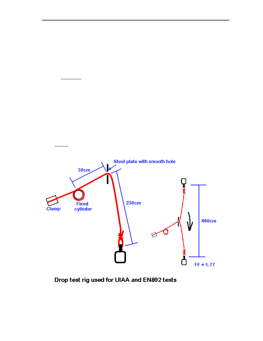
Life on a line
12:
Rope
testing
156
Another point to note is the exact design of the rig can be quite variable. In the BS/EN test the
rig shown as an example ties the rope to the falling mass using a figure-8 knot, but the
anchored end is not knotted, instead it passes several times around a large cylinder then the tail
is clamped in a vice. This allegedly makes sure that the only knot to be tested is the one at the
moving end, but it has questionable effects on the data compared to the normal ‘between two
knots’ designs. Also, the rope passes over an edge in the BS/EN design, simulating a fall where
the mid-point of the rope is held on a running belay, such as with a lead climber fall. Normal
drop test rigs do not incorporate this modification, as it is difficult to engineer cheaply and
reliably. Personally, I would suggest that for testing of semi-static rescue/caving ropes the
straight-line test is more relevant to real-world events, since falls on running belays are very
unlikely using these types of rope.
The older UIAA drop test uses the same idea of a rope falling over an edge – in this case a
karabiner. A 2.8m length of rope is clamped at one end, run around a fixed clynder then
through a ‘karabiner’ 30cm away, and the resulting 2.3m of rope used to create a 4.6m length-
of-fall for an 80kg or 55kg block. This makes a fall factor of 1.77 and the UIAA tests define
how many falls a rope should take and the peak force on the rope during each fall. Again, it is
engineered to simulate falls in climbing, not in caving and rescue work, where the more
common ‘fall’ is a short drop of a very heavy object with the force applied directly to the
anchors. You can argue that ‘directly to the anchors’ is rare, but in rescue we deviate ropes
using pulleys – so there is trivial loss of energy in friction.

Life on a line
12:
Rope
testing
157
12b2. The NCA Drop test
The NCA in the UK has a programme of rope drop-testing for semi-static caving ropes, using a
purpose-built rig that is owned and operated by the NCA. It will test ropes sent to it from
anywhere in the UK. The NCA test uses a sequence of five drop-tests using a 100kg mass and a
length of rope knotted using two figure-8 loops. The rope is soaked in water for at least 2 hours
and tested immediately, while still wet. This is meant to reproduce caving conditions. The rope
is a short length running directly between a frame and the load with no intermediate edge as for
the EN tests.
The five drops use fall factors of 1.0, 1.0, 1.1, 1,2 and 1.3 with a ‘pass’ condition being failure
on or after the third drop.
This exceeds the EN1891 standard (of five FF 1.0 drops using 100kg) so that the rope is likely
to fail during the test. If all the ropes passed the test then predicting decay would be more
difficult, so the NCA test deliberately exceeds the original standard in an attempt to force
failure. It therefore does not reflect a rope’s approval under the EN standard, though normally
brand new ropes made to EN 1891 type A will survive at least the first four drops.
Data on the ropes tested is collated by the NCA and it is hoped to be of benefit for predictive
work in the future.
12b3. The LOAL rescue drop test
This test system is designed specifically for semi-static rescue ropes and will not be of use for
normal caving ropes of less than 11mm diameter, or dynamic ropes. It is designed to be a
compromise between the EN standard for testing, and the loads seen in rescue work. The
principle is that for rescue ropes the loads are higher, but in general the fall factors expected are
smaller.
The test is performed on a wet rope, soaked for at least 2 hours as for the NCA test. A length of
rope is tied into a single span between figure-9 knots so that under tension of 70kg the knots
reach between points 100cm apart. The knots are secured to a fixed frame and to the falling
load, which should be a 200kg mass.
The following set of drops is performed:
1. Static hang of the load from the rope with no fall, to tension the knots. The length
between knots is measured at this point.
2. FF 0.25
3. FF 0.25
4. FF 0.5
5. FF 0.75
6. FF 1.0 repeated until failure
After each drop the length between knots is recorded.

Life on a line
12:
Rope
testing
158
Ideally a serviceable 11mm rope should retain enough strength to pass drop test 4 or 5. Given
the uses of semi-static ropes with rescue loads, we know already that a drop of fall factor
greater than 0.5 will be assumed to cause failure of all the associated equipment (anchors,
pulleys, karabiners etc) and so that is the serviceable criteria which I propose for the test.
However, until data starts coming back to me on ropes and results it is too early to say if this
proposed pass/fail level is realistic.
One advantage of the LOAL sequence in terms of practicality of course is that the fall factors
do not exceed 1.0, so a catch-plate test rig or something similar is not required. I must say for
the benefit of all the lawyers who are waking up at this point, that neither the NCA nor the
LOAL test sequence claim in any way to reproduce or compare to the stated requirements of
the BS/EN standards. For that, you must do 5 unity fall factors with a 100kg mass – no more,
no less, no cheating.
12b4. The before and after
Once you have found out where to send your rope samples for testing, or built your test rig,
then choosing the rope samples should not be a random affair. There is a major implication to
volunteer rescue teams in drop testing – that to test a rope you need to cut off a section, hence
drop tests gradually destroy your rope inch-by-inch. However, hopefully drop tests are at most
a yearly event, so if your rope has an expected lifetime of 2 to 3 years, it can afford to be a few
metres shorter every Xmas.
Many people find out that the tester has asked for a 2m sample of rope, so cut 2m off the end of
their rope and send it in. This is simply silly – that last section of your rope has had far less use
than the rest of it – you KNOW not to tie off anchors with the last few inches, and for most of
your callouts at least 10 metres stayed in the tackle bag. On average, the most abused section of
a semi-static caving rope is the section between 1 and 4 metres in from the end. This is the
section that receives all the rigging knots, also it is where SRT devices are fitted and removed,
which can damage the rope through the action of toothed cams and so on. This is therefore the
area of the rope that you most want to test – if this passes then the rest should be stronger. I
suggest therefore that the policy for taking a drop-test sample is to cut back a 1m length, then
take your sample for the tests.
You of course will make sure that both the sample and the freshly-shortened rope are relabelled
correctly and the change in length recorded on the PPE sheet, lest someone on a descent
question your lineage when a 50m pitch is not adequately spanned by your new 47m rope.
The ultimate question however is what to do with the rope when the results come back. No
home-designed test (or even the two tests described earlier) will give you a legally-binding
yes/no to your question of the rope’s lifetime. Hopefully as the years pass, more and more data
will be collated on drop tests, and a better idea of the way they relate to the PPE regulations
will emerge. In the meantime, all we can say is that if a sample of rope shows a significant loss
in performance compared to a sample of the same rope when new, you must clearly have to
question the continued use of the rope by your team. If you have the funds or connections to
replace ropes with great regularity, you may not even want to bother doing drop tests, instead
choosing to replace your ropes every year or two without debate. However, I would ask that
teams retiring well-used ropes without needing a drop test would be helping the work of the
NCA and others a great deal by sending a sample in for testing anyway – to bolster the
databases. If you have accurate usage data on a rope then often the manufacturer themselves

Life on a line
12:
Rope
testing
159
will appreciate a few metres posted back to them for testing, since rescue teams are considered
reliable when they give usage data when perhaps individuals and sportsmen are not.
12c. Other tests
Drop tests are the simplest and quickest way for an ‘amateur’ to get an idea of the strength of a
rope, however there are many other ways to collect data if you have the equipment, time and/or
enthusiasm. The problem is that apart from data collated by the rope manufacturers, few people
are measuring anything other than drop test results, so the potential benefit of other data in
predicting strength and lifespan is as yet unknown. These include:
• Tensile strength pull-tests (straight or knotted rope)
• Elongation under load
• Peak impact force measurements in drop tests
• Cyclic bending tests
• Drop tests over a sharp edge
A lot of these tests require access to measuring equipment (dynamometers and so forth), and
their data is not of direct benefit to rope owners, so they are not viable except for research.
However, specific effects can be more accurately measured using some of these tests (such as
the slight reduction in tensile strength due to chemical exposure), where drop tests add too
much complexity. A drop test applies many stresses to a rope, from the energy of the fall to the
compression of the knot and the pressure-wave effects of water within the core, and so often
the rope fails, but for an unclear reason. Ropes are complex pieces of mechanical engineering,
with far more moving parts and interacting factors than the devices they are used with. The way
they age, and the reasons they fail, are often a mystery that only time and the collection of
hundreds of test results will explain.
12d. The specifications for rope
Whilst not of direct relevance you may like to know the specifications used by the two EN
standards for kernmantel rope.
Semi-static ropes comply with EN 1891, and can be issued with one of two type codes. Type A
ropes are the norm, and apply to all ropes greater than 9.5mm diameter. Type B ropes (9.5mm
and less) are of a lower performance and are specifically intended for use by people using extra
care and precautions. They need greater protection from damage as the safety margins are
lower, however they are still capable of taking human loadings safely.

Life on a line
12:
Rope
testing
160
Test parameters for EN 1891
Limit for type A Limit for type B
Shock force, F
The peak force transmitted to an anchor point during
a fall factor 0.3 with a mass of M kg shall not exceed
6kN
M = 100kg
M = 80kg
Number of falls, N
Using a 2m length of rope tied with figure-8 loops on
a rig producing fall factor 1.0 drops, the rope must
survive five or more falls at intervals of 3 minutes
using a mass of M kg.
M = 100kg
M = 80kg
Elongation, E
The percentage change in length of an unknotted
sample of rope which occurs between loads of 50kg
and 150kg
E <= 5%
Knotability, K
A single overhand knot is tensioned with a 10kg
force for one minute. The force is reduced to 1kg and
the internal diameter of the knot measured. K is this
internal diameter divided by the diameter of the rope
K < 1.2
Sheath slippage, S
A 2m length of the rope is drawn through a pulling
rig (a constriction specified in the EN document) 5
times. The slippage of the sheath is recorded in mm.
S <= (10D – 180)
where D = rope
diameter
S <= 15
Sheath ratio, M
The mass of the sheath divided by the total mass of
the rope
30% < M < 50%
Static strength, T
The breaking force of an unknotted rope in clamps
T > 22kN
T > 18kN
Knotted static strength, Tk
The breaking force of a length of rope tied with two
figure-8 knots and under tension for 3 minutes
Tk > 15kN
Tk > 12kN
The EN standard also requires that the rope contain an internal identification filament or ribbon
that shows by colour code the year of manufacture. Each end of a new rope must be marked
with the name of manufacturer, type of rope (A or B), diameter, CE mark and EN number and
the identifier of the test house approving the rope. Some manufacturers also print this data on
the internal ribbon, but that is not part of the CE specification.
There is another EN standard, EN564, which refers to ‘accessory cord’. This has been used by
some manufacturers on specialist ropes of less than 9mm but has no bearing for rescue.
EN892 covers dynamic kernmantel ropes. Although it lives in the ‘mountaineering equipment’
section of the EN structure rather than the ‘falls from a height’ section, the requirements are
very similar. There are two main classes of rope in the standard, ‘full ropes’ and ‘half ropes’. A
half rope (marked ½ on the ends) is of lower performance and is intended for use doubled-up.
Full ropes (marked ‘1’ on the ends) can be used on their own. Some people refer to the classes
as ‘single’ and ‘double’ ropes, but this is to be avoided. Obviously for rescue work only full
ropes are suitable. There are also newer classes of rope – ‘double’ and ‘walking’ ropes have
lower standards again, and their intended uses are limited.

Life on a line
12:
Rope
testing
161
There are also many variants on dynamic ropes beyond the EN892 specification. ‘Gym ropes’
are engineered to be more robust near the ends, others have special coatings and treatments to
make them slippier, less water-absorbent and so on. All must eventually pass the EN tests
however, and these optional add-ons are not yet included in the standards.
Test parameters for EN892
Limit for type A Limit for type B
Shock force, F
The peak force transmitted to an anchor point during
a fall factor 1.77 with a mass of M kg shall not
exceed F kN. The test uses the UIAA drop rig.
M = 80kg
F < 12kN
M = 55kg
F < 8 kN
Dynamic elongation, D
The peak extension recorded in the first drop test in
the test above for shock loading
D < 40%
Number of falls, N
Using a the same rig for shock force, the rope must
survive five or more falls at intervals of 3 minutes
using a mass of M kg.
M = 80kg
M = 55kg
Elongation, E
The percentage change in length of an unknotted
sample of rope which occurs with a load of 80kg
E <= 8%
E <= 10%
Knotability, K
A single overhand knot is tensioned with a 10kg
force for one minute. The force is reduced to 1kg and
the internal diameter of the knot measured. K is this
internal diameter divided by the diameter of the rope
K < 1.1
Sheath slippage, S
A 2m length of the rope is drawn through a pulling
rig (a constriction specified in the EN document) 5
times. The slippage of the sheath is recorded in mm.
S <= 40mm (or 2%)
Under the EN892 specifications, there are no specific limits for the static strength of the rope.
This is the main reason why drop-testing is used by most programmes to research the ageing of
ropes, since for EN892 ropes the other factors are often unknown. The UIAA specification is
the same as above except for a change to the slippage S, making it 20mm rather than 40mm. As
a result almost all dynamic ropes are manufactured to comply to both EN/CE and UIAA
approvals.

Life on a line
13:
Contamination
&
Disinfection
162
13. Contamination and disinfection
This is a new idea, and has not been a part of a ‘caving’ book before, though is a common topic
in the medical field. The common-issue British caver is recognised worldwide for the sallow
expression caused by years of engrained silt and mud, and would never be seen dead sporting
equipment that isn’t worn to a claggy brown by years of isolation from any form of detergent.
This is all well and good, but the rescue team equipment officer, every now and then, gets a
hank of rope to wash that’s more of a red colour courtesy of the remains of the person they just
recovered. Washing and disinfecting team kit can be more of a challenge than just dunking it in
water like the usual caver would do, as many of the procedures to remove infectious hazards
from equipment are also likely to damage the strength and lifetime of ropes and slings. Within
the UK in 2001, the national outbreak of Foot and Mouth disease also awoke questions on what
to do with team equipment that has been used in a ‘contaminated area’ where there may be
legal requirements on cleaning that contradict care instructions.
13a. Overview
‘Contamination’ in this chapter refers specifically to materials present on ropes and equipment
that do not in themselves present a direct risk to the equipment, but may present a health risk to
the user. If your equipment is exposed to solvents or acids then it is likely to be damaged even
if you wash it afterwards, and the continued use of that equipment would be irresponsible.
However, biological materials (body fluids, infectious agents and so on) can leave equipment
undamaged but dangerous. ‘Disinfection’ is the specific term to describe the treatment of
equipment to remove the risk of infection. This is subtly different to decontamination – you can
disinfect something by killing the bacteria or viruses on it but without washing them off.
Decontamination is the process of removing the harmful substances with or without killing
anything.
Provided that they can be removed safely, the equipment can be returned to use. The word of
importance of course is ‘safely’ – cleaning agents can be just as destructive to ropes and
harnesses as any other chemicals, so it is vital to ensure that how you clean does not affect the
equipment.
The non-biological forms of decontamination, including removal of chemicals and radioactive
particles, will not be considered in this chapter. Within the cave rescue community it is unlikely
that equipment will be exposed to these risks except in extremely rare accidental circumstances.
Teams are not trained to handle ‘hazmat’ incidents and so would never be called on to
intentionally expose themselves or their kit to such contaminants. In the rare event of an
accidental exposure that only comes to light after the team are on scene, it would be expected
that any contaminated equipment would be impounded by the regulatory agencies. We will
instead concentrate on biomedical contamination from the casualty or from the environment (as
in Foot and Mouth).
In medicine there are two types of disinfection – containment and reuse. Containment
disinfection is done to prevent the spread of a hazard (for example washing equipment before
removing it) from a localised site of contamination, known as a hot zone. Reuse disinfection is
to clean the equipment to the point it can be reused in safety. Containment disinfection is often

Life on a line
13:
Contamination
&
Disinfection
163
limited by the facilities available and the needs of the situation, whereas reuse disinfection can
be a more considered and complex process. Obviously, processes that require the items to be
taken to a facility (pressure autoclaving or irradiation) are not options for containment.
For a rescue team there are only specific circumstances where containment disinfection is
required. Some we have already experienced in the UK (such as the F&MD outbreak), others
(such as biochemical accidents or terrorist acts) have not.
In many cases of a hot zone the statutory agencies in supervision will have standing orders on
the methods of disinfection and decontamination. This applied in the F&MD outbreak when a
list of approved disinfectants and dilutions was issued. This list unfortunately was incompatible
with the materials in rope rescue equipment, and this in part led to the decisions imposed
restricting the response of UK teams to farm sites. Luckily, there was an equally universal
closure of sport caving, so there were no callouts to restricted farms. If the situation arises in
the future and a standing order list is issued, then it is likely that any equipment used on an
infected site would have to be quarantined or disposed of. National guidelines should be issued
by the BCRC in the event of a national outbreak.
13b. Biomedical disinfection
This leaves the main risk of biological contamination from a casualty, in terms of blood and
other body fluids. The obvious risks presented are twofold – does the body fluid present an
infection risk to people using the equipment in future, and is it capable in itself of damaging the
equipment?
Body fluids, with the possible exception of vomit due to its acidity, present no structural risk to
metallic or rigid plastic equipment beyond the simple ability to clog up working parts.
Tests outlined in section 2a2 noted that both blood and urine could have a detrimental effect on
the strength of nylon and polypropylene fibres, although blood only has a minor effect. Vomit,
by the fact that it is acidic, is also detrimental to nylon but less so to polypropylene. There is
clearly an issue of cleaning the equipment as soon as possible to prevent any chemically
induced damage, but if ropes or webbing were left for prolonged periods without being cleaned,
then you would be well advised to consider them unserviceable.
Body tissues picked up during a rescue will usually be contaminated by blood, but the tissue
itself presents no risk to the integrity of ropes and webbing. Body tissues can however be very
hard to clean if left to desiccate, in particular brain tissue. There is a specific question on
decontamination of items exposed to brain tissue as the infectivity with respect to prion
diseases (CJD etc) is not yet fully understood. However, the direct risk from prion diseases is
only significant from direct surgical contact with previously contaminated equipment, which
would be unlikely with rescue equipment, possibly excepting protective headgear used by a
team on casualties.
In terms of infection risk to subsequent users (both during the rescue and during cleaning), then
blood, faeces and to a limited extent vomit are capable of transferring infectious pathogens.
Urine is sterile on production and presents no biological risk.
As an aside, none of the current BCRC-approved medications present a material risk to rescue
equipment.

Life on a line
13:
Contamination
&
Disinfection
164
13c. Cleaning agents
There are obviously two categories of equipment to deal with. Metallic or plastic components
can be cleaned using more aggressive chemicals than fibres and ropes.
Under the terms of the PPE Directive (Annex 2, section 1.4) all equipment must be supplied
with information on cleaning and disinfection. The response to this is often limited to the bare
minimum, as manufacturers are rightly reluctant to suggest exposing their equipment to any
aggressive chemicals if at all possible. Many either state ‘washing in warm water’ or using a
diluted solution of ‘compatible disinfectant’ without stating what that may be. Legally, a
manufacturer has to provide such information on request to enable a user to satisfy their
obligations to disinfect equipment, and so the rule seems to be to ask first and wash later!
Some general guidelines are however known, based on the data issued by some more
forthcoming manufacturers and extrapolated based on the known composition of their products.
The old-fashioned universal disinfecting agent was to soak for at least an hour in a 1% solution
of hypochlorite bleach in water, however this is alkaline and presents a small risk to all
synthetic yarns, especially if used to soak the material for a long time. It is certainly suitable for
any metallic equipment, although is rarely suggested by manufacturers in case the dilution is
used incorrectly. One trick from the EMS field when using a bleach solution to disinfect fabrics
is to alternate 5-minute soaks with rinses, as it helps prevent the protein in blood denaturing
and making a permanent stain.
Modern disinfectants are usually based on ammonium compounds mixed with a chlorohexidine
solution. When diluted to working strength these are reasonably pH-neutral, and so present
little risk to either metallic or woven equipment. DMM, amongst others, recommends using a
lukewarm water solution (20C or less) of a generic disinfectant (such as Savlon) for treating
their harnesses and equipment, by soaking for an hour then rinsing thoroughly in lukewarm
water. They specifically state that the washing and rinsing solutions must lie within the pH
range 5.5 to 8.5.
Petzl, on the other hand, show a graphical recommendation in their product instruction manuals
of an aqueous ethanol solution at 30C, again soaked for an hour. This applies to all their
products including harnesses, mechanical devices and helmets. Polypropylene is resistant to
ethanol, however nylon is not. The ethanol solution must be rinsed off thoroughly. However, a
statement issued by the Petzl technical engineers in March 2003 states:
‘Petzl… no longer recommend the use of ethanol… Disinfection should be by soaking in plain
water at 30 degrees C for one hour then rinsing in plain water’
We are awaiting more useful information from Petzl, following our reply that soaking in water
is not, to the best of our knowledge, a recognised method of disinfecting anything that is not
already sterile. Petzl claim that their change of position on ethanol is due to the complexities of
dilution. It goes to show that whilst manufacturers have a duty under the PPE Directive, they
seem reluctant to keep to it. Rest assured that as soon as someone in Petzl makes a move, we
will update this page!
One thing to note about disinfection through soaking – you may not actually make the
equipment look any cleaner unless you scrub it too – but it will be biologically safe. Once
disinfected, a normal washing process should be used to spruce up any marks, if only for visual

Life on a line
13:
Contamination
&
Disinfection
165
effect. Whenever a mechanical device has been disinfected, you may of course have to re-
grease the internal parts in accordance with the manufacturer’s guidance.
Ultimately, before applying any chemicals to an item of safety/PPE equipment you should take
reasonable steps to ensure that it is not going to harm it in any way. This usually is (and until
they release data up front will continue to be) via contacting the manufacturer directly and
telling them the product and nature of the contamination you wish to remove. However, this is
plainly an unacceptable way of working, as replies can take weeks, during which your
equipment is unusable. As we have said, some biological contaminants can have a detrimental
physical effect on fabrics and yarns, so we suggest that while you await advice from a man
behind a desk somewhere on the other side of the world, you wash the item normally to remove
as much as possible of the offending contaminant, lest it reduce your expensive equipment to
scrap while your case is considered and coffee is drunk.
Above all, please remember that the safety of your team and your casualties, both in terms of
the strength of your equipment and any risks it may present from contamination, is never worth
the cost of replacing it. If, of course, you have to replace an item then you may wish to consider
the ease of disinfection, or the ease of obtaining help with disinfection, as part of your process
of choosing a new supplier.

Life on a line
14: Training for rescue teams
166
14. Training for rescue teams
This chapter will undoubtedly raise the hackles of cave rescue team stalwarts across the
country, who will point out that (a) I claimed that this was not a training manual, and (b) that
they are doing just fine thank you without being told how to teach someone to knot string.
Well fine on both counts, I am not in a position within the pages of a book to teach caving
skills, teamwork or the routes through your local haunts – however a great number of rescue
teams in the UK have little or no crossover to industrial (I will avoid using the term
‘professional’ to save getting beaten up) teams and training. Historically, rescue teams learnt by
taking experienced cavers and making them attend practices and callouts until they inherited
the skills they needed from a combination of watching and trying, akin to my medical
methodology of SODOTO (see one, do one, teach one). This has merits of course, but it is
pretty inefficient. Suppose you were to learn to drive entirely by hanging around with your
mates – you could pick it up sure enough, but would you pass the theory test?
What I intend to do in this chapter is show some of the training techniques used for industrial
teams (including the armed forces and Fire Service) and how they could be applied to helping
create better skill bases in a volunteer team. None of what I say is gospel, and you are perfectly
free to put down the book at this point and carry on as you have been. However, if you feel like
expanding your methods a bit, or you are on the cutting edge of teaching and want to see if you
can catch me out, then read on… there will be a test at the end of the semester.
14a. Training riggers
The rigger is the heart of the team in terms of ropework. In a typical UK team callout structure,
they rarely figure. The typical structure is:
1. Team controller (usually also the surface controller)
2. Underground controller or captain
3. Pitch captains
4. Groups and individuals
I omit medical specialities as that is, I hope, a separate structure on your callout. The medic
needs to be devoted to the casualties and not burdened with other roles. Also, whatever the
medic says goes if it bears on the care of the casualty.
In the above structure, levels 2 and 3 would need to be riggers, the man at level 1 need not be
but an overall skills base is vital to efficiently manage his team. Within reason, people at level
4 need only to be able to follow directions and perform self-progression.
A different structure, based on the military system, is to have levels 3 and 4 replaced by
independent groups each including (and headed by) a rigger, and able to operate on any task
they are assigned. A team of say 3 people could be told to rig a traverse, search a lower series
or lay in the telephones, and they would do the job without further instruction. This makes the
underground controller independent of the technical details of the rescue – he may decide the

Life on a line
14: Training for rescue teams
167
route to be taken, but the ropes and anchors used are dealt with by the groups. This is all nice
and efficient and adaptable, but it requires that a rigger running a team can achieve pretty much
anything as long as he is given the equipment. This is where rigger training comes in – riggers
should be able to accomplish anything in this book, plus all the intricacies of normal self-
progression (by which I mean moving personally through the environment using SRT or other
methods). They need to be able to improvise and make decisions on the routes and rigs they
construct in advance of the casualty arriving, so they need some appreciation of stretcher
handling too.
I am not implying that a rigger is some all-knowing being that can rescue someone single-
handed while rousing guitar music plays and credits roll. There are many things that a rigger
does not need to know at all – such as the system he is in. As long as one person in the group
knows the routes and anchors, the rigger can consult them for help. He does not need to be a
medic – ideally someone else in the group should be, but he needs only to understand about
how to handle the team’s stretchers.
Above all, a rigger needs to have a ‘rescue brain’. This is something that you can only teach by
specific practice and training, since it often contradicts their personal brain:
A personal brain
is presented with an obstacle and thinks of how he would get past it, using
his skills as a caver
A rescue brain presented with an obstacle thinks of how to get the casualty past it and
implement all of the extra systems that entails, from backup lines to hauling systems.
There are often contradictions – during a search of a vertical system, a personal caver may
decide a 5ft pitch is trivially free-climbable, or just needs a short ladder or handline. A rescue
brained rigger would see that as a major obstacle for a stretcher, so while he may fit a fast
handline to get his search group down, he is also starting to plan more anchors, ordering up
another rope and gear kit and so forth. There are many cases underground where an obstacle is
trivial to sport cavers and so has never been anchored, so there is a time element in placing
them. The rigger may decide in the first few seconds that this ‘trivial’ obstacle makes the entire
route too difficult to use and so plans a search for others. It is not about picking a knot quickly,
it is about standing back for a few seconds and making a call on the entire scene.
This mental separation from the scene is a learned skill just like anything else. Some people are
also a lot more adept at it than others – some can assimilate the information from an
environment and analyse it very quickly, others have to sit and think a while. This may not be a
bad thing so long as they come to the right answer when they do, but a rigger also has to be in
charge of the system he has built when it is being used – when failures and problems need
instant and decisive solutions. Some can handle it, some cannot. It’s the same in all emergency
roles; there are thinkers, doers and followers.
We have decided on a shopping list for a rigger’s training:
• Full knowledge of all aspects of rescue ropework (i.e. all of this book!)
• Ability to absorb a scene and construct a solution efficiently and without help
• Adaptive to problems (lack of gear, uncooperative rock and so on)
• Appreciation of handling a casualty and stretcher
• Team leadership skills

Life on a line
14: Training for rescue teams
168
The last bit is important – a rigger cannot usually do all the ropework himself, so he must be
very efficient at transferring the mental images in his head to instructions that his group can
implement. It is no good shouting at people when they can’t see what you are aiming for, and
there is no easy way underground to gather around a table with pen and paper.
To get to this point you need to start of course with a competent vertical caver. Moving
personally through the systems he is rigging needs to be second nature – to go Zen for a
moment I have been known to tell students that a good rigger ‘flows’ through the ropework, not
climbs past it. Just as a police driver cannot be expected to learn pursuit if he has problems
driving himself to work in the morning, you have to pick your men. This can create political
tensions in a volunteer team, with the Animal Farm arguments bubbling up about people being
more equal than others, however in a professional team the idea of specialism and ‘rank’ is
perfectly normal, so passing that onto volunteers is not a bad thing. People complaining that the
riggers are getting to much power and kudos can be reminded that there’s nothing stopping
them trying for the same job.
Given a good vertical caver, then the first thing to do is get their rescue brain installed. It is
unlikely that you would select a new recruit for rigging, so we can assume that the trainee has
been on many team practices or callouts and so has seen the system in action, but it can surprise
trainers how little team members know about what they are being asked to do. Attending
practices and callouts for years may not help one jot in learning the rules of redundancy and
tension on traverses. There is a big element therefore of sending the trainee off for a little while
to read up on the differences with rescue rigging (the basic rules and premises) before throwing
them into the details.
Learning and practicing the techniques (hauling systems, anchors and so forth) are best done
outside the normal team events, but with other riggers if it helps. Some trainees will prefer a 1-
on-1 with a trainer, as they prefer to make mistakes in private. Others will like the group-based
approach, but they cannot be allowed to hide within it. One thing is clear though – there is no
time on a team practice to teach riggers anything useful. To absorb a new technique or item of
equipment most people will need to go over and over the same practice pieces until it sinks in –
doing it once with 50 men watching is not going to help someone learn, for a short while they
may remember enough to copy it again but long-term they do not learn the how’s and why’s. I
suggest therefore that the training of riggers be planned completely independently of team
practices, which can be used as ‘examinations’ for the riggers’ new skills.
A technique commonly used for efficient professional training is the notion of the ‘skill
station’. Here a group of trainees alternate individually between set-piece exercises designed
to deal with a specific skill (such as rigging a Z-rig or placing bolts). A short timescale and
repeated changes help the students to remember what they learn since they do not have time
to get bored. Beyond this are events – larger tasks that may need one or more students at a
time, and take longer to implement. Examples include rigging a traverse or constructing a
set of anchors in an awkward position. It can help greatly in these events to have a small
group of ‘professional assistants’ on hand, who can act under the direction of the rigger and
follow their instructions but are told not to offer advice.
Some trainers let their students watch each other, some do not. It is a matter of preference,
however if you are not one for voyeurism then a group debriefing session is vital after the
practicing, so that different solutions can be debated. Often there is no one correct method, and

Life on a line
14: Training for rescue teams
169
learning from others helps prevent the student getting locked into their own set of ‘favourite
fixes’. Bad habits are difficult to pass on but easy to keep to yourself.
Without a formal hierarchy there can be issues during training where the trainer reprimands
someone and they take offence to being told off. As a trainer you must learn to handle your
students impeccably – you will sometimes make mistakes yourself, or a student will see a better
way of doing something, so accept humility is part of the job just as is authority.
Also your job as a trainer is to be constantly questioning your students on why and what they
are doing and thinking. Give them frequent ‘what-if?’s to answer, and vary the parameters of
the exercise if you see that your students have got embedded in a solution and are no longer
watching the bigger picture. There is a fine line in getting this right – you can easily get a
reputation as an impossible taskmaster, but remember that volunteer or not, these people are
training to save lives in an extreme environment where they will be planning and installing the
systems without help – if you do not feel confident in them, they are not ready. I do not want
you to think that I am aiming at a military system of regimented instruction and obeyance, as
that cannot operate efficiently without all the other factors of discipline that the military system
enforces. However, playing about in a group of friends is equally unable to turn out skilled and
efficient cave rescuers.
Simple components
Several simple techniques and scenarios have been shown to be of use in training riggers,
including:
• Tabletop exercises
• Rigging using less than adequate equipment (improvisation)
• Rigging in extreme positions (very tight pitches, waterfalls, loose rock, etc)
• Pop-quiz random questions (‘which is stronger, a bowline or a figure 8?’)
• Impossible exercises (where the goal is to see if the student realises it’s impossible)
These are commonly used for industrial and military training as they can help instil the rescue-
related aspects of the work independently of the sport caving techniques. Some examples are
given later in this chapter.
Testing and validation
In a volunteer team there is usually no formal structure of testing and validation of team
members for rigging as there is for ‘external’ skills like first aid. At present there is limited
benefit in having external or national ‘qualifications’ for rigging, though industrially this is in
place in some cases and being adopted in others. Teams tend to shy away from anything
involving a course and an exam, if only for the fact it costs money, but I would suggest that
there is no justification NOT to implement some internal system. To a caver with no first aid
skills, the work of a paramedic can seem illogical and mind-boggling, and to that paramedic the
notion of SRT and reading the safety of a boulder slope by eye can seem equally beyond
humanity. A rescue team member wishing to gain medical abilities assumes that it will involve
examination and ‘approval’, so why not for a rigger? One of the primary aims of this book was
to demonstrate that rescue rigging is not just an extension to sport caving, it is a whole different

Life on a line
14: Training for rescue teams
170
skill in itself. You need one to do the other, but you also need to learn and remember things you
will never want, or need, to apply on a sporting trip.
Strictly on a personal level I would like to see a set of recognised standards for cave rescue
rigging training, though I would not wish to see that used to justify charges and fees. The life of
the casualty is in the hands of the riggers just as much as it is in the hands of the medics, and if
for no other reason than the inevitable call of litigation, teams should know what their members
know and be able to prove to some extent why they believe them to be competent. It would be
tempting to push in an extra chapter here with syllabi and examination schedules, but that is for
the national bodies to debate, this book is here to document techniques, not politics. Teams
should however seriously consider an internal method of keeping track of who has been trained
in what, and if need be have an ability to control the duties each team member is permitted to
use on a callout to reflect their training.
14b. Relationships to industrial qualifications
Rather neatly this brings us on to the external qualifications that
riggers can obtain. Almost all of the time this is via their
occupation, though some regions have tried using external training
when deals have been brokered. The NWMRA, for example, has
sent candidates from it’s member teams to a commercial rope
rescue training centre within their locality which is commonly
used by the Fire Service, as a way of crossing over skills. The
danger with all industrial qualifications is that they can engender
bad habits when applied to the underground world, so in some
cases an industrial rope worker can be a liability on a cave rescue
unless they can adapt to the territory.
In the UK the national body responsible for the rope access
industry is IRATA, which has a multi-level training and
certification programme for its members. A combination of
accrued time, practical and theoretical examinations by assessors
gives a candidate certification for a set period of time, and this is
usually a pre-requisite of employment in the UK rope access trade.
The IRATA rigging methods are regimented and documented, and
reflect the need to comply with HSE regulations, so concentrate
strongly on backups and redundancy. There is also a healthy dose of PPE, both of which are of
help in rescue work, but are not in any way designed to work with rescue loads. An IRATA
technician is trained to perform unaided rescue of a stranded SRT worker but is not trained in
the use of hauling and stretcher systems except at the higher specialised levels. IRATA does
not deal with confined space rescue.
There is hardly any benefit in a team member going out and getting an industrial qualification
(for one, it costs a great deal!), but if they gain one via work then it can help them on the team –
however watch that they do not start over-enforcing their workplace regulations.
Personal qualifications (such as CMLA / cave leader, instructor and so on) are not of any
significant benefit to cave rescue rigging. They may show an individual is a good vertical

Life on a line
14: Training for rescue teams
171
caver, but there is usually no rescue element to the training except impromptu self-rescue and
assistance.
Some teams will have access to the training facilities used by the emergency services or armed
forces (Fire Service training sites are often well-equipped for ropework, with lots of nice
towers). Whilst gaining access to use the sites for team/rigger training can be difficult, there is a
great benefit in getting team riggers to attend and observe these other agencies in action. On a
major incident, cave rescue teams can call on the Fire Service or armed forces to assist (or vice
versa) and they have a dramatically different way of doing things. After watching the Fire
Service ‘rope rescue unit’ train at a location in the UK a while ago I can say with confidence
that the sorts of equipment and techniques they rely on would scare the caplamp off a cave
rescue rigger, so a healthy knowledge of the differences is an enormous benefit before
expecting a group of ‘outsiders’ to understand what a Z-rig-tensioned Tyrolean will look like.
Finally, it has to be said that callouts are a good form of training in themselves. I stress of
course that a callout is not the time to be learning how to rig a pitch, but you can often do
things on callouts that you cannot justify doing on practices (the placing of anchors on sensitive
sites, etc) and so a debrief and inspection after the rescue is of great benefit to those involved
(or those who missed that callout). I have lost track of the number of times in rope training (and
also on medical courses) that the infamous sentence
“If this was for-real we would do ---------- but we won’t as it’s a practice... you get the idea…”
is heard. This is all well and good for the trainer, as he probably has done it for-real. Be wary of
letting your students off without ever trying it for want of the waste of a rope or a handful of
metal. The buzzword in paramedical training now is immersion training – everything is done to
make the training seem, look, feel and smell like the real thing. An infamous Welsh doctor
teaching rescue teams in the 1980’s was know to have a secret clan of amputees on hand for the
ultimate realistic injury… I am not suggesting you go that far (burying yourself so you can get
dug out is pushing it a bit), but the idea of simple things to make it real is worth striving for.
This is expensive and so for volunteer teams can be difficult, but the closer to reality you can
get the better you will be when reality is what you’re in. Typical example is rigging a traverse –
you know it’s a lot harder when there are no footholds, so find somewhere to practice where
there aren’t any! Don’t haul an empty stretcher, fill it with a bodyweight of sandbags or rope.
14c. Scenarios
Finding ‘interesting’ scenarios and skill stations to train on is the hallmark of a good instructor.
This comes often with time, but also with available resources – if you’re based in Kent then
training on a 1000ft mineshaft presents some logistical issues. Here I have tried to put down a
few suggested scenarios and the ways you can alter them as they progress to stir the little grey
cells of the riggers you are teaching. There are benefits in just taking the gear out of your team
store once every few weeks and ‘playing’ with it – in the UK the majority of rescue teams do
not get enough callouts to keep their members as familiar with their own kit as the statutory
emergency services are, and it can be surprising how quickly the exact method of lacing up a
stretcher or bolting together your winch frame can be forgotten!

Life on a line
14: Training for rescue teams
172
If you’re in the mood to try out some evil (or fun, depending on your viewpoint) scenarios with
your riggers, maybe some of the below will get you going:
1. Hauling and lowering on a tight vertical pitch
a. Insist on a few changes in direction without warning
b. Try restricting the gear available (especially for the hauling system)
c. Try a counterbalance haul instead of a top-based haul
2. Hauling and lowering on a slanted pitch
a. Using deviations and guidelines to send the stretcher down clear of the rock
b. Simulate a jam or the failure of a belay
3. Tyrolean traverses
a. Using a highly-sloping runway
b. Using limited anchors at one or both ends
c. Crane-jib traverses for picking and placing a load at marked points on the floor
of a gorge (add a time element if you wish to make it nasty)
4. Knotty traverse (an evil notion)
a. Transport of a heavy stretcher keeping it exactly horizontal
b. A combination pitch (a traverse leading out to a vertical lower with no
footholds, truly a hideous job for any rigger)
5. Limited anchors
a. Using props and non-standard devices to secure loads
b. Working with anchors a long way apart (more difficult than it sounds)
c. Bolt-placement for hauling systems
6. Water
a. Hauling systems on wet pitches
b. Tyroleans and traverses over open water
There is also a method of practicing and training called ‘lights out’. This is common in the
military and used to be used a lot in maritime ropework, simply out you learn to recognise and
do your job in the dark. It is difficult to apply this to every aspect of cave rescue rigging, but in
theory it is possible to do. SRT relies on contact with the rope, and without light you should be
able to operate by feel. Clearly you cannot place anchors and rig pitches in the dark, but you
can practice making and using hauling rigs, tying and untying knots and using the commercial
equipment in your kitbags. A competent rigger should be able to take a bag of rope and gear
and make up any hauling or belaying system with his eyes closed, it is an interesting and
challenging way to see how good you really are! I do not have to say that lights out training is
not done in a cave with no caplamp – you cannot train someone not to walk off a pitch! Playing
in a dark room or with a blindfold on is just as useful, and the blindfold method helps as the
instructor can watch!
14d. Training and insurance
This is a little section but important. When on a callout, members of a cave rescue team are
insured both personally and against liability, either by the team or by the statutory agency that
calls them out. On training and practice events however the insurance may not apply in the
same sense. This can raise three issues that teams need to look into before adopting the idea of
independent training sessions for riggers:

Life on a line
14: Training for rescue teams
173
1. Is the team equipment insured against loss or theft if not on a full team callout?
2. Are the team members covered for third-party liability against landowners?
3. Is access to training sites conditional on item 2?
Most team members will be active cavers and have personal liability cover, either through a
club or directly. However, it could be argued that a team training session is not covered by
‘sport’, specifically if using rescue-specific methods. Also, agreements to use private sites such
as quarries and commercial buildings that some teams have in place may be based on the idea
that the team provides insurance, which may only apply on ‘official’ team practices. This is
often true when the team’s insurance is provided by the Police, who will only sanction it for
pre-arranged official events, often limiting the number of these events in a single year.
The most important aspect of training is confidence in your own abilities. You cannot train for
every situation, nor can you supply all the equipment to handle every obstacle. A rigger’s role
is to pass the obstacle using the resources he has, in his hands and in his head. He must trust
both.

Life on a line
15: The future of rescue ropework
174
15. The future of rescue ropework
This chapter has been interesting to plan. A few years ago I would have said that the general
future of cave rescue was to carry on as it is now, having a bit more paperwork and legal stuff
to handle but generally hiding from the public as cavers tend to do. With the changes in the
world in the last few years, potential roles for cave rescue teams have emerged that were not
thought of beforehand. The events of 9-11 have shown that it can be all too possible for a major
confined-space rescue to be needed at any place, at any time.
Cave rescue teams have a wealth of expertise in working in extreme environments that is
unparalleled in the emergency services. Their combination of high-angle rope rescue, confined
space working, rock drilling and digging, searching and recovery, even diving and explosives,
mean that they are in a prime position to develop closer links to ‘surface’ rescue structures in
the future. That is not to say that the primary and most common role is not to help those in
danger underground, and that the volunteer caver system of recruitment should change. Cave
rescue teams will always exist to help cavers; that is fundamental. However the encroaching
needs to meet legal standards of record-keeping, training and operational readiness mean that
the team is increasingly worth more than just as a service to a niche sport. Whether teams start
to adopt these other roles depends on politics, and the willingness of the members. Personally I
can see an increased use of cave rescue teams to assist, and even respond primarily, to surface
rope rescue and confined space incidents. This would involve closer cooperation between the
teams and the statutory bodies (Fire Service, Coastguard and so on), as well as changes to the
training and approval of teams. The mountain rescue community is evolving now to meet these
new challenges, with increasing regulation of training and widening of roles; historically cave
rescue follows the MRC in things like this, so it is to be expected eventually.
The one thing that we know will change in UK voluntary rescue work is the impact of EU
regulations. At present ‘rescue’ falls neatly between the bars of the PPE framework and the
CE/EN standards, and this will have to change. More than likely will be an imposed
requirement to comply completely with PPE ‘work’ regulations for any team serving to rescue
members of the public, irrespective of their status. EN standards specifically for rescue
equipment are in the pipeline, as are subtle changes to the existing raft of standards to account
for higher loads. New CE/EN standards are not retrospective, so it will not affect the equipment
you own already – but it may influence your choices in the future. Issues like team member
training are likely to be influenced by legislation in the same way that medical training is being
influenced now. During 2003/2004 all team members dealing with a casualty will be required
to hold a valid and approved first aid qualification, the same could easily be argued for the
technical aspects of rigging and ropework. This is not the same as requiring all team members
to hold a local cave leader or CI badge, that is simply proof of personal ability in the sport.
Rescue ropework is a skill in itself, and as such I believe deserves recognition.
Within the UK cave rescue has always been a volunteer-run and volunteer-staffed service
offered for free to those needing assistance underground. Whilst the encroaching legal
requirements mean that teams have to increasingly operate on a professional basis in terms of
skills and paperwork, I firmly believe that to remove the volunteer basis would damage the
service irrevocably. Hopefully by not charging anyone for LOAL I am making a hint to all the
other generators of paperwork, rules and regulations that the one thing teams do not need is a
bill.

Life on a line
16:
References
175
16. References
A large amount of the non-numeric data in this book (techniques, procedures and designs for
rigging) are based on the author’s experience and the common practices of UK cave and
industrial rescue teams and riggers. Data on the performance and use of commercial devices is
obtained in all cases from the manufacturer, either by reference to the supplied instruction
manuals or by direct contact with the product engineers.
Specific numerical data has been quoted based on published sets of research or from direct
information supplied by manufacturers and/or third-party tests. Whilst the author cannot be
responsible for error or omission in this external data, it is safe to assume that data from reliable
sources is equally reliable, and so we have only used sources from official research or standing
rescue teams. Data collected by individuals and published non-professionally (such as via a
personal or club website or magazine) is not used in this book.
16a. General ropework books
Whilst not all specifically aimed at underground rescue, these books may be of interest. A lot of
the data on knot strength has been derived from these books (averaging out where there is
disagreement). All of the books are written and aimed at the US market.
• Rope rescue for firefighting by Ken Brannan (ISBN 0912212616)
• Engineering practical rope rescue systems by Mike Brown (ISBN 0766801977)
• Technical rescue riggers guide by Rick Lipke (ISBN 0966577701)
• Confined space and structural rope rescue by Mike Roop (ISBN 0815173830)
• High angle rescue techniques by Tom Vines (known as HART) (ISBN 0815159001)
• On Rope by Bruce Smith et.al. (ISBN 1879961059)
• The essential technical rescue field operations guide by Tom Pendley (ISBN 0967523826)
• CMC rope rescue manual ed. by James Frank (ISBN 0961833777)
16b. Equipment test reports
Published data on the performance of ropes and equipment has been taken from many sources,
usually via the manufacturer to confirm the reliability of the data. Some specific sources
include:
• Eco-anchor test results from Les Sykes of the CNCC (published via their newsletter)
• Info on the Petzl I`D was sourced via Lyon Equipment (
www.lyon.co.uk
)

Life on a line
16:
References
176
• Some data on the high-load performance of belay devices came from Technical Rescue
magazine (
www.technicalrescuemagazine.com
)
•
www.dsm.com/hpf/support/rcn/fiberprp/~en/mainfric.htm
has data on friction
calculations and results for Dyneema
•
www.techrescue.org/vertical/vertical-ref4.html
has calculations and suggestions on the
loads on Tyrolean traverses (aerial ropeways)
•
www.tensiontech.com/papers/fiber_id/index.htm
has data on the identification of fibres
within ropes and webbing
•
www.dsm.com/hpf/support/rcn/fiberprp/~en/creep01.htm
discusses the plastic
deformation and creep of Dyneema
•
www.wireworld.com/fiberline/yarntabl.html
has data on the performance of several
synthetic yarns used in ropemaking
All other data relating to the performance of commercial equipment is sourced from the
manufacturer.
16c. Standards and Government sources
The official text of BS/EN standards is available to purchase from the HMSO catalogue at
www.the-stationery-office.co.uk
. Some extracts are published on the Web, the full text is not.
The PPE Regulations website at
europa.eu.int/comm/enterprise/newapproach/standardization/harmstds/reflist/ppe.html
has FAQs and extracts from the current Regulations, plus a downloadable link to the proposed
new version of the Regulations, not yet in force.
16d. Other sources of information
Within the UK any official guidance for cave rescue teams should be obtained through the
BCRC and the team insurers. Many teams are also affiliated to the local Mountain rescue
Association in their area, and the MRC has an open-access newsgroup server at
news.mountain.rescue.org.uk, which can be a useful place to ask for opinions and comments.
16e. Terms used in this book
The majority of rope rescue texts are from the USA. Terms used for climbing equipment, knots,
rigging procedures and for caving often differ across the Pond, so we have stuck as rigidly as
possible to a set of terms and definitions as given below. This book is squarely aimed at rescue-
team cavers of some experience so unambiguous terms (karabiner, etc.) are used without
explanation. The lists below cover terms that (certainly beyond the UK) cavers may use for
entirely different purposes, and so if you are reading this book from a house in the USA you
may need this section as a translation tool!
I have borrowed terms from both caving and climbing throughout this book, hopefully clear to
all readers and in agreement with ‘Climbing terms and techniques’ (Crocket, 1990).

Life on a line
16:
References
177
Ropes etc.
LINE
refers to a length of rope rigged to perform a specific function (e.g. as an SRT line
on a pitch or as part of a hauling system), as opposed to something lying about with
no intended use.
ROPE
is the generic term for load-bearing ropes, including one still in a bag.
CORD
is any rope less than 9mm in diameter and deemed not fully load-bearing (e.g. as
used for prusik loops, footloops etc).
BUNGEE
is a kernmantel construction cord with elastic (rubber) cores used for tensioning in
non load-bearing situations (e.g. to keep a chest jammer in position)
WEBBING is woven load-bearing material either in a flat profile or produced in an endless
tube, as used to create belay slings, quickdraws or belts.
TAPE
in this book refers only to adhesive tape and not to webbing.
WIRE
refers to metal rope of a laid construction, used for slings, tethers and to produce
items such as electron ladders.
When put to a specific use lines have the following standard names:
SRT LINE
is a static rope fixed in position and intended for the use of one or more
cavers to climb or descend using personal single rope techniques.
BELAY LINE
is a static (or dynamic) rope that provides a safety backup in the event of
primary system failure but which in normal use experiences no loading. It
also refers to a dynamic rope used to protect a lead climber (as is usual in
rock climbing).
HAULING LINE
is a static rope used to support a casualty, items of equipment or other
dead-weights during controlled raising and lowering, and which is in
tension in normal use.
SAFETY LINE
is a dynamic or static rope routed around a hazard and acts as a point for
cavers to attach to. It is a fall-arrest device and is not loaded under normal
use. An example would be a loop of rope connecting together a group of
cavers working near the top of a pitch. Do not confuse a SAFETY line
with a BELAY line. SAFETY lines exist around specific hazards, BELAY
lines are used to protect objects being moved by hauling systems, or lead
climbers.
SPAN LINE
is a static rope or wire spanning between anchors in a traverse
TOW LINE
is a static rope or cord fixed to the travelling pulley(s) on a traverse and
used to pull them along the span lines.
Normal UK caving terms are used for line and rope rigging that forms part of the normal sport
caving repertoire (such as ‘deviation’, ‘traverse line’, ‘rebelay’ etc).
Mechanical devices
AUTOBLOCS
are knots that are designed to wrap around a fixed rope and grip it, usually
in one direction only. The prusik, bachmann and penberthy knots are
autoblocs.
ASCENDERS
refer to any device used to climb a rope by mechanical gripping or friction,
and is a group term including rope clamps, autoblocs and other devices.

Life on a line
16:
References
178
ROPE CLAMPS
are mechanical rope-climbing tools involving a toothed cam gripping
against the rope, such as the well-known Basic, Croll and Expedition
devices by Petzl, the Kong, Jumar and Rescuecender and many others.
Also referred to as ‘jammers’. All ascenders are not rope clamps – the
terms specifically refers to a device with a cam action.
DESCENDERS
refer to any controlled-friction device specifically designed to allow
descent of a fixed line. The term includes basic devices such as the figure
8, plus PACDs such as the Stop.
PACD
(Positive Action Camming Descenders) are mechanical devices which
generate friction by the passage of rope around two or more fixed cams,
parts of which are designed to move together under the action (or inaction)
of the user and which grip the rope to prevent further descent. The Petzl
Stop, I`D and SRT descenders are the most common examples of PACDs.
BECKET
is a little-known term for the fixed attachment ring built into many pulleys
opposite the main attachment point and intended to tie off the rope when
building compound pulley systems.
Other devices and terms.
PITCH
is any vertical drop in a cave (a shaft, winze or opening into a cavern) which
requires ropes or ladders to negotiate. The ‘flat’ ground at the top of a pitch is
called the ‘PITCH HEAD’. Standard terms for other natural features of caves
are used.
BELAY
is the process (or devices intended for…) the protection of a moving climber or
object using a controlled point of friction. The important point is that a belay
system is not under load until something goes wrong. If the rope is under
tension at all times it ceases to be a belay and instead becomes a hauling line.
KARABINER
is a metal ring with a spring-loaded gate as usual. Rather than fight over the
choice of spelling (KAR… or CAR…) I have chosen the version suggested by
the Oxford English Dictionary.
BOLT
is a metal device sunk into rock to provide an attachment point and can be
secured by resin or expansion. Strictly speaking in the UK a ‘bolt’ refers to the
device set into the rock and the metal attachment ring is a ‘HANGER’, though
there is little point in having one without the other. I will use the term ‘bolt’ to
refer to any point of attachment that is fixed into a hole in rock by whatever
means, as ‘hanger’ can cause some confusion when talking about hauling rigs
and loading.
ANCHOR
is the generic term for any fixed point of attachment (for a rope or other
object). It includes bolts, natural rock features of suitable strength and design,
trees, car axles, small buildings and piles of exhausted cavers. Care should be
taken to note that the term ‘belay’ as used in the USA to refer to an anchor is
used in this book to refer to something completely different.
TETHER
is a flexible strap (usually with eyes on both ends), produced from webbing,
wire, chain or rope and designed to wrap around a large diameter anchor to
provide a suitable point of attachment.
SLINGS
are endless sewn or tied loops (usually of webbing or rope) designed for
similar purposes as tethers.

Life on a line
16:
References
179
QUICKDRAWS
are short slings (usually 20cm circumference) and used in the climbing world
to join two karabiners together into a flexible ‘runner’. In this book quickdraws
are used for several parts of hauling systems where a small extra length is
needed between objects.
SRT
(single rope technique) is the group of methods used by a caver to ascend or
descend a single fixed ropes by means of mechanical devices fixed to his
person. If the control of the movement is from somewhere else, that caver is no
longer conducting SRT, instead he is the load in a hauling system.
ELECTRON LADDER
is (for our international readers) a metal flexible ladder produced
from thin steel wire (usually 4mm diameter max) and designed to support one
body mass in ascent or descent. It is usually fitted at the top with a
SPREADER
(a short y-shaped wire tether) that brings the two wires together
at a single attachment point.
ACROW
is a cannibalised trade name for a steel prop with an adjustable length, usually
achieved by a threaded collar and pin system. Used for supporting a weak roof
or to fix across a passage to provide a rapid anchor point.
MAILLONS
(maillon rapides) are metal oval, D-shaped or triangular rings with a screwed
sleeve covering an opening. Called ‘quicklinks’ or ‘screwlinks’ in the USA and
beyond.
The chapter on knots and rope uses many terms for the parts of a knot, the components of
ropes, etc. which are detailed where first used
A final note to those of you who have got this far…
Creating this book has taken a lot longer than expected, partly from other constraints on my
time but mostly from the rarity of data in the public domain. I would like to think that the
questions raised throughout this book will lead to more rescue-rated test data becoming
available, and one day letting this book quote numbers that everyone agrees on! Finally I would
like to say that if anyone feels like writing another version of LOAL, then I for one would be
eager to read it… and good luck to you!
Dave M
[somewhere between his PC and a large bottle of Black Sheep…] March 2003
This is the end of part three of the three-part edition
This part was last modified on 06 Mar 2003
Changes in this issue: Inserted pic and text into 10b, some tinkering with indexes and page breaks.
Life on a
Line
Digitally signed
by Life on a Line
DN: cn=Life on a
Line, o=Draftlight
Network
Services, c=GB
Date: 2003.05.11
12:45:38 Z
Signature
Not Verified
Wyszukiwarka
Podobne podstrony:
LIFE ON A ROPE cz II
LIFE ON A ROPE czI
Cz III Ubezpieczenia osobowe i majątkowe
Dziady cz III
dziady cz III salon
Podstawy Pedagogiki Specjalnej cz III Surdo B
Kulawizna u koni cz III(1)
HLN CZ-III R-06, Kozicki Stanisław
Prawo rzymskie cz III prawo osobowe z czynnościami prawnymi
60 64 IB 7 8 2006 Techn proj cz III
Dziady cz III
NOWOTWORY CZ. III, IV rok Lekarski CM UMK, Patomorfologia, patomorfologia, ćwiczenia, semestr zimowy
cz III (1 11)
03 01 2012 Kinezyterapia cz III
Metody modelowania procesow 2012 cz III
więcej podobnych podstron