
Sponsored
by:
Structured Cabling
Supplement
Cisco Networking Academy Program
CCNA 1: Networking Basics v3.0

Objectives
The Structured Cabling Supplement for CCNA provides curriculum
and laboratory exercises in seven areas:
a. Structured Cabling Systems
b. Structured Cabling Standards and Codes
c. Safety
d. Tools of the Trade
e. Installation
Process
f. Finish
Phase
g. The Cabling Business
This material and the associated labs provide a broad introduction to
structured cabling installation.
The section on Structured Cabling Systems discusses the rules and
subsystems of structured cabling for a local-area network (LAN). A
LAN is defined as a single building or group of buildings in a campus
environment in close proximity to one another, typically less than two
square kilometers or one square mile. This supplement starts at the
demarcation point, works through the various equipment rooms, and
continues to the work area. The issue of scalability is also addressed.
The learning objectives for Structured Cabling Systems are as
follows:
1.1 Rules of Structured Cabling for LANs
1.2 Subsystems of Structured Cabling
1.3 Scalability
1.4 Demarcation Point
1.5 Telecommunications and Equipment Rooms
1.6 Work Areas
1.7 MC, IC, and HC
The section on Structured Cabling Standards and Codes introduces
the standards-setting organizations that establish the guidelines used
by cabling specialists. Important information about these international
standards organizations is included.
2 - 125 CCNA 1: Networking Basics v3.0 – Structured Cabling Supplement
Copyright
2003, Cisco Systems, Inc.

The learning objectives for Structured Cabling Systems and Codes
are as follows:
2.1 Telecommunications Industry Association (TIA) and Electronic
Industries Association (EIA)
2.2 European Committee for Electrotechnical Standardization
(CENELEC)
2.3 International Organization for Standardization (ISO)
2.4 Codes for the United States
2.5 Evolution of Standards
The Safety section contains important information that is often
overlooked when discussing low voltage telecommunications wiring.
Students that are not accustomed to working in the physical
workplace will benefit from the labs and training in this section.
The learning objectives for Safety are as follows:
3.1 Safety Codes and Standards for the United States
3.2 Safety Around Electricity
3.3 Lab and Workplace Safety Practices
3.4 Personal Safety Equipment
The Tools of the Trade section discusses how various tools can help
turn a difficult job with ordinary results into a simple job with
outstanding results. This module gives students hands-on experience
using several of the tools that telecommunications cabling installers
rely on for professional results.
The learning objectives for Tools of the Trade are as follows:
4.1 Stripping and Cutting Tools
4.2 Termination Tools
4.3 Diagnostic Tools
4.4 Installation Support Tools
The Installation Process section describes the elements of an
installation. This chapter begins with the rough-in phase, when the
cables are pulled into place. This section also discusses riser or
backbone cables, the fire-stops used when a wire passes through a fire
rated wall, copper terminations, and fixtures such as wall adapters.
3 - 125 CCNA 1: Networking Basics v3.0 – Structured Cabling Supplement
Copyright
2003, Cisco Systems, Inc.

The learning objectives for Installation Process are as follows:
5.1 Rough-In Phase
5.2 Vertical Backbone and Horizontal Cable Installation
5.3 Fire-Stops
5.4 Terminating Copper Media
5.5 The Trim Out Phase
The Finish Phase section discusses the point at which installers test
and sometimes certify their work. Testing ensures that all the wires
route to their appointed destination. Certification ensures that the
quality of the wiring and connection meet industry standards.
The learning objectives for Finish Phase are as follows:
6.1 Cable Testing
6.2 Time Domain Reflectometer (TDR)
6.3 Cable Certification and Documentation
6.4 Cutting Over
The Cabling Business section discusses the business side of the
industry. Before cables can be installed, there must be a bid. Before
there can be a bid, there must be a request for a proposal, and several
meetings and walk-throughs to determine the scope of the work.
Documentation may be required to describe the project and show how
it was built. Licenses and union membership may also be required to
perform the work. All projects must be performed in a timely manner
with minimal waste of materials. This usually requires project
planning and program management applications.
The learning objectives for The Cabling Business are as follows:
7.1 Site Survey
7.2 Labor Situations
7.3 Contract Revision and Signing
7.4 Project Planning
7.5 Final Documentation
Lab exercises give students the opportunity to practice the manual
skills portion of structured cabling installation.
4 - 125 CCNA 1: Networking Basics v3.0 – Structured Cabling Supplement
Copyright
2003, Cisco Systems, Inc.

1 Structured Cabling Systems
1.1 Rules of Structured Cabling for LANs
Structured cabling is a systematic approach to cabling. It is a method
for creating an organized cabling system that can be easily
understood by installers, network administrators, and any other
technicians that deal with cables.
There are three rules that will help ensure the effectiveness and
efficiency of structured cabling design projects.
The first rule is to look for a complete connectivity solution. An
optimal solution for network connectivity includes all the systems
that are designed to connect, route, manage, and identify cables in
structured cabling systems. A standards-based implementation is
designed to support both current and future technologies. Following
the standards will help ensure the long-term performance and
reliability of the project.
The second rule is to plan for future growth. The number of cables
installed should also meet future requirements. Category 5e, Category
6, and fiber-optic solutions should be considered to ensure that future
needs will be met. The physical layer installation plan should be
capable of functioning for ten or more years.
The final rule is to maintain freedom of choice in vendors. Even
though a closed and proprietary system may be less expensive
initially, this could end up being much more costly over the long
term. A non-standard system from a single vendor may make it more
difficult to make moves, adds, or changes at a later time.
Web Link:
http://www.panduitncg.com/NCG_SYSSOL/ncg_syssol_pm/ncg_sys
sol_pm_markets/Finance/rules.asp
5 - 125 CCNA 1: Networking Basics v3.0 – Structured Cabling Supplement
Copyright
2003, Cisco Systems, Inc.
1.2 Subsystems of Structured Cabling
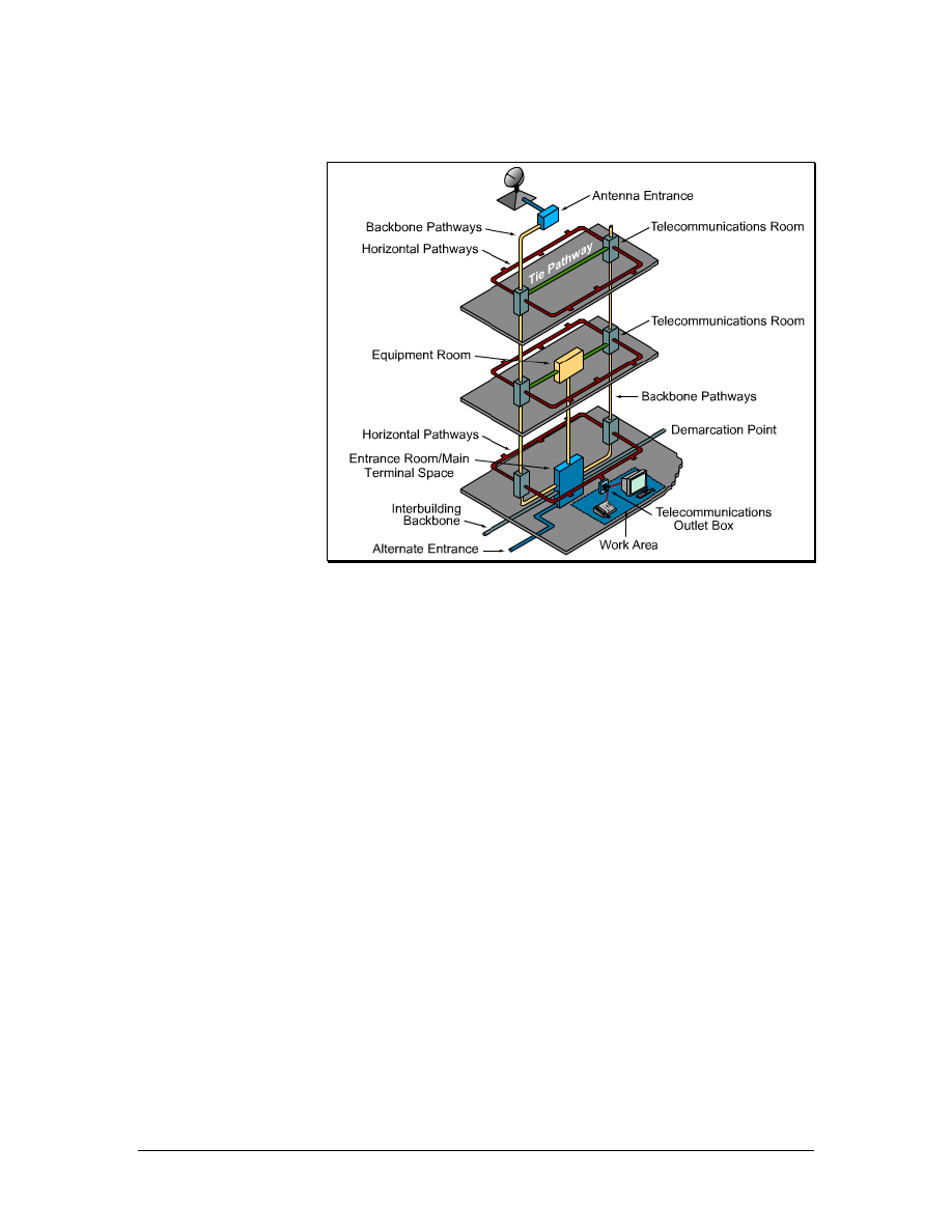
Figure 1 Subsystems of Structured Cabling
There are seven subsystems associated with the structured cabling
system, as shown in Figure 1. Each subsystem performs certain
functions to provide voice and data services throughout the cable
plant:
• Demarcation point (demarc) within the entrance facility (EF)
in the equipment room
• Equipment room (ER)
• Telecommunications room (TR)
• Backbone cabling, which is also known as vertical cabling
• Distribution cabling, which is also known as horizontal
cabling
• Work area (WA)
• Administration
The demarc is where the outside service provider cables connect to
the customer cables in the facility. Backbone cabling is the feeder
cables that are routed from the demarc to the equipment rooms and
then on to the telecommunications rooms throughout the facility.
Horizontal cabling distributes cables from the telecommunication
rooms to the work areas. The telecommunications rooms are where
connections take place to provide a transition between the backbone
cabling and horizontal cabling.
6 - 125 CCNA 1: Networking Basics v3.0 – Structured Cabling Supplement
Copyright
2003, Cisco Systems, Inc.

These subsystems make structured cabling a distributed architecture
with management capabilities that are limited to the active
equipment, such as PCs, switches, hubs, and so forth. Designing a
structured cabling infrastructure that properly routes, protects,
identifies, and terminates the copper or fiber media is absolutely
critical for network performance and future upgrades.
1.3 Scalability
A LAN that can accommodate future growth is referred to as a
scalable network. It is important to plan ahead when estimating the
number of cable runs and cable drops in a work area. It is better to
install extra cables than to not have enough.
In addition to pulling extra cables in the backbone area for future
growth, an extra cable is generally pulled to each workstation or
desktop. This gives protection against pairs that may fail on voice
cables during installation, and it also provides for expansion. It is also
a good idea to provide a pull string when installing the cables to make
it easier for adding cables in the future. Whenever new cables are
added, a new pull string should also be added
1.3.1 Backbone scalability
When deciding how much extra copper cable to pull, first determine
the number of runs that are currently needed and then add
approximately 20 percent of extra cable.
A different way to obtain this reserve capability is to use fiber-optic
cabling and equipment in the building backbone. For example, the
termination equipment can be updated by inserting faster lasers and
drivers to accommodate fiber growth.
7 - 125 CCNA 1: Networking Basics v3.0 – Structured Cabling Supplement
Copyright
2003, Cisco Systems, Inc.
1.3.2 Work area scalability
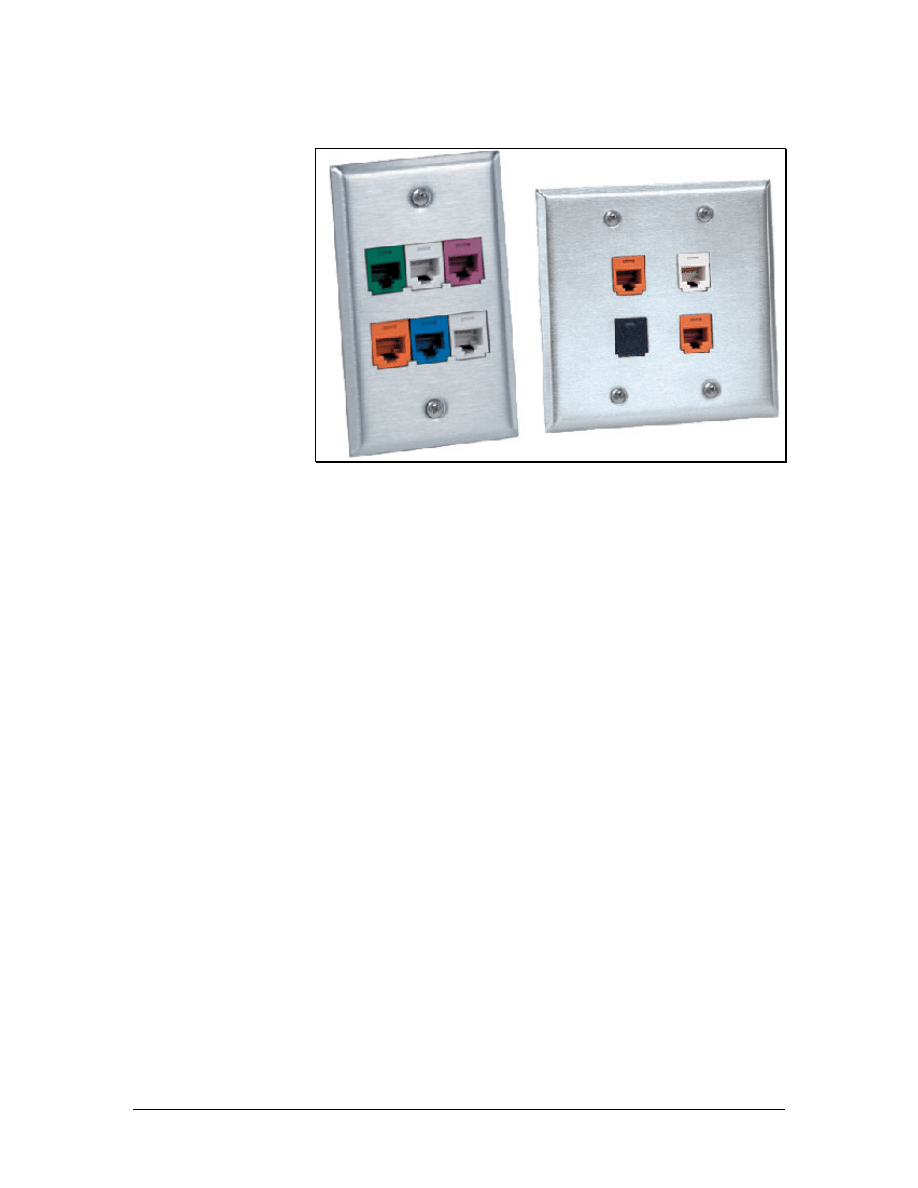
Figure 1 Allow for Growth
Each work area needs one cable for voice and one for data. However,
other devices may need a connection to either the voice or the data
system. Network printers, FAX machines, laptops, and other users in
the work area may all require their own network cable drops.
After the cables are in place, use multiport wall plates over the jacks.
There are many possible configurations for modular furniture or
partition walls. Color-coded jacks can be used to simplify the
identification of circuit types, as shown in Figure 1. Administration
standards require that every circuit should be clearly labeled to assist
in connections and troubleshooting.
A new technology that is becoming popular is Voice over Internet
Protocol (VoIP). This technology allows special telephones to use
data networks when placing telephone calls. A significant advantage
of this technology is the avoidance of costly long distance charges
when VoIP is used over existing network connections. Other devices
like printers or computers can be plugged into the IP phone. The IP
phone then becomes a hub or switch for the work area. Even if these
types of connections are planned, enough cables should be installed to
allow for growth. Especially consider that IP telephony and IP video
traffic may share the network cables in the future.
To accommodate the changing needs of users in offices, it is
recommended to provide at least one spare cable to the work area
outlet. Offices may change from single user to multiuser spaces. This
can result in an inefficient work area if only one set of
communication cables was pulled. Assume that every work area will
accommodate multiple users in the future.
8 - 125 CCNA 1: Networking Basics v3.0 – Structured Cabling Supplement
Copyright
2003, Cisco Systems, Inc.
1.4 Demarcation Point
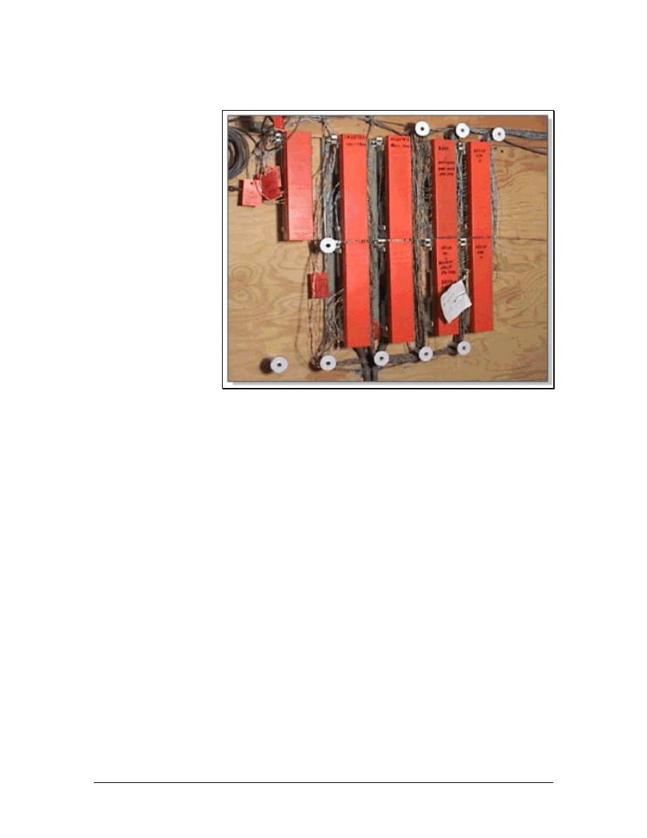
Figure 1 Demarcation Point
The demarcation point (demarc), shown in Figure 1, is the point at
which outdoor cabling from the service provider connects to the
intrabuilding backbone cabling. It represents the boundary between
the responsibility of the service provider and the responsibility of the
customer. In many buildings, the demarc is near the point of presence
(POP) for other utilities such as electricity and water.
The service provider is responsible for everything from the demarc
out to the service provider facility. Everything from the demarc into
the building is the responsibility of the customer.
The local telephone carrier is typically required to terminate cabling
within 15 m (49.2 feet) of building penetration and to provide
primary voltage protection. The service provider usually installs this.
The Telecommunications Industry Association (TIA) and Electronic
Industries Alliance (EIA) develop and publish standards for many
industries, including the cabling industry. To ensure that the cabling
is safe, installed correctly, and retains performance ratings, these
standards should be followed during any voice or data cabling
installation or maintenance.
The TIA/EIA-569-A standard specifies the requirements for the
demarc space. The standards for the structure and size of the demarc
space are based on the size of the building. In buildings larger than
2,000 square meters (21,528 sq ft), a locked, dedicated, and enclosed
room is recommended.
9 - 125 CCNA 1: Networking Basics v3.0 – Structured Cabling Supplement
Copyright
2003, Cisco Systems, Inc.
The following are general guidelines for setting up a demarcation
point space:
• Allow 1 square meter (10.8 sq feet) of plywood wall mount
for each 20-square meter (215.3-sq feet) area of floor space
• Cover the surfaces where the distribution hardware is
mounted with fire-rated plywood or plywood that is painted
with two coats of fire retardant paint
• Either the plywood or the covers for the termination
equipment should be colored orange to indicate the point of
demarcation.
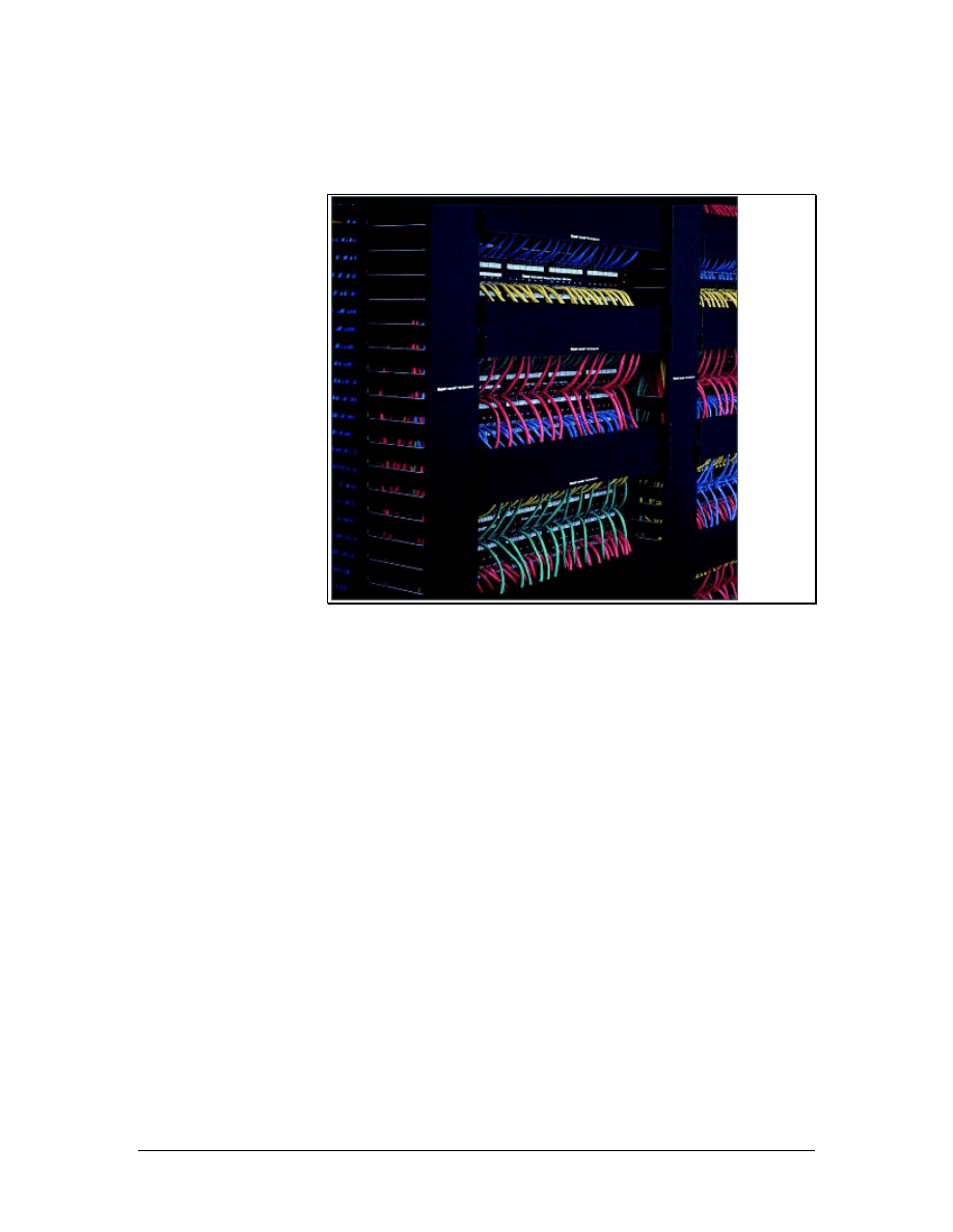
1.5 Telecommunications and Equipment Rooms
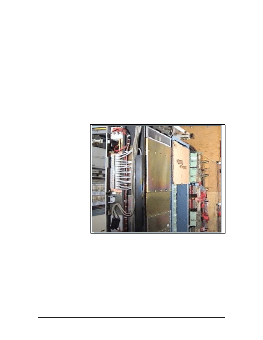
Figure 1 Telecommunications Room
10 - 125 CCNA 1: Networking Basics v3.0 – Structured Cabling Supplement
Copyright
2003, Cisco Systems, Inc.
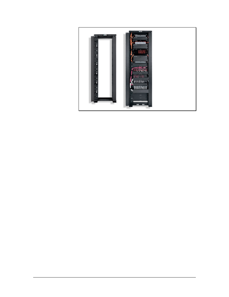
Figure 2 Panduit Distribution Rack
After the cable enters the building through the demarc, it travels to
the entrance facility (EF), which is usually in the equipment room
(ER). The equipment room is the center of the voice and data
network. An equipment room is essentially a large
telecommunications room that may house the main distribution
frame, network servers, routers, switches, the telephone PBX,
secondary voltage protection, satellite receivers, modulators, high
speed Internet equipment, and so on. The design aspects of the
equipment room are specified in the TIA/EIA-569-A standard.
In larger facilities, the equipment room may feed one or more
telecommunications rooms (TR) that are distributed throughout the
building. The TRs contains the telecommunications cabling system
equipment for a particular area of the LAN such as a floor or part of a
floor, as shown in Figure 1. This includes the mechanical
terminations and cross-connect devices for the horizontal and
backbone cabling system. Departmental or workgroup switches, hubs,
and routers are commonly located in the TR.
A wiring hub and patch panel in a TR may be mounted to a wall with
a hinged wall bracket, a full equipment cabinet, or a distribution rack
as shown in Figure 1.
A hinged wall bracket must be attached to the plywood panel that it
covers the underlying wall surface. The hinge allows the assembly to
swing out so that technicians can easily access the backside of the
wall. It is important to allow 48 cm (19 inches) for the panel to swing
out from the wall.
A distribution rack must have a minimum of 1 meter (3 feet) of
workspace clearance in the front and rear of the rack. A 55.9-cm (22-
inch) floor plate is used to mount the distribution rack. The floor plate
11 - 125 CCNA 1: Networking Basics v3.0 – Structured Cabling Supplement
Copyright
2003, Cisco Systems, Inc.
will provide stability and determine the minimum distance for the
final position of the distribution rack. A distribution rack is shown in
Figure 2.
A full equipment cabinet requires at least 76.2 cm (30 inches) of
clearance in front for the door to swing open. Equipment cabinets are
generally 1.8-m (5.9-feet) high, 0.74-m (2.4-feet) wide, and 0.66-m
(2.16-feet) deep.
When placing equipment into equipment racks, consider whether or
not the equipment uses electricity. Other considerations include cable
routing, cable management, and ease of use. For example, a patch
panel should not be placed high on a rack if a significant number of
changes will occur after the installation. Heavier equipment such as
switches and servers should be placed near the bottom of the rack for
stability.
Scalability that allows for future growth is another consideration in an
equipment layout. The initial layout should include extra rack space
for future patch panels or extra floor space for future rack
installations.
Proper installation of equipment racks and patch panels in the TR will
allow for easy modifications to the cabling installation in the future.
1.6 Work Areas
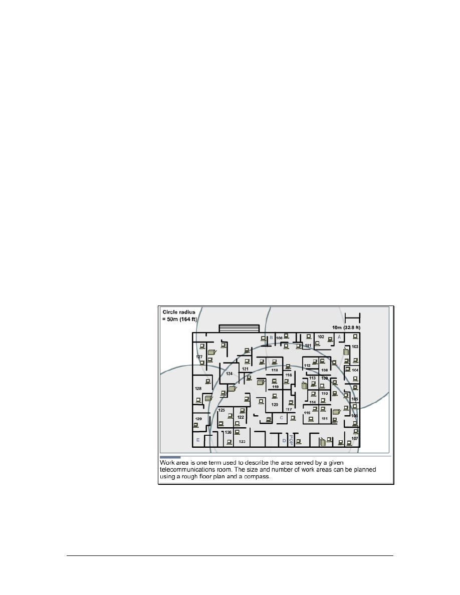
Figure 1 Work Areas
A work area is the area serviced by an individual TR. A work area
usually occupies one floor or part of one floor of a building, as shown
in Figure 1.
12 - 125 CCNA 1: Networking Basics v3.0 – Structured Cabling Supplement
Copyright
2003, Cisco Systems, Inc.
The maximum distance for a cable from the termination point in the
TR to the termination at the work area outlet must not exceed 90
meters (295 feet). This 90 meter maximum horizontal cabling
distance is referred to as the permanent link. Each work area must
have at least two cables. One for data and the other for voice. As
previously discussed, accommodations for other services and future
expansion must also be considered.
Because most cables cannot be strung across the floor, cables are
usually contained in wire management devices such as trays, baskets,
ladders, and raceways. Many of these devices will route the paths of
the wires in the plenum areas above suspended ceilings. The ceiling
height must then be multiplied by two and subtracted from the
maximum work area radius to allow for wiring to and from the wire
management device.
ANSI/TIA/EIA-568-B specifies that there can be 5 m (16.4 feet) of
patch cord to interconnect equipment patch panels, and 5 m (16.4
feet) of cable from the cable termination point on the wall to the
telephone or computer. This additional maximum of 10 meters (33
feet) of patch cords added to the permanent link is referred to as the
horizontal channel. The maximum distance for a channel is 100
meters (328 feet), the 90-meter (295 feet) maximum permanent link
plus 10 meters (33 feet) maximum of patch cords.
Other factors may decrease the work area radius. For example, the
cable routes may not lead straight to the destination. The location of
heating, ventilation, and air conditioning equipment, power
transformers and lighting equipment may dictate paths that add
length. After everything is taken into account, a maximum radius of
100 m (328 feet) may be closer to 60 m (197 feet). A work area
radius of 50 m (164 feet) is commonly used for design purposes.
1.6.1 Servicing the work area
Figure 1 Servicing the Work Areas
13 - 125 CCNA 1: Networking Basics v3.0 – Structured Cabling Supplement
Copyright
2003, Cisco Systems, Inc.

Patching is helpful when connectivity changes occur frequently. It is
much easier to patch a cable from the work area outlet to a new
position in the TR than it is to remove terminated wires from
connected hardware and reterminate them to another circuit. Patch
cords are also used to connect networking equipment to the cross-
connects in a TR. Patch cords are limited by the TIA/EIA-568-B.1
standard to 5 m (16.4 feet).
A uniform wiring scheme must be used throughout a patch panel
system. For example, if the T568-A wiring plan is used for
information outlets or jacks, T568-A patch panels should be used.
The same is true for the T568-B wiring plan.
Patch panels can be used for Unshielded Twisted Pair (UTP),
Shielded Twisted Pair (STP), or, if mounted in enclosures, fiber-optic
connections. The most common patch panels are for UTP. These
patch panels use RJ-45 jacks. Patch cords, usually made with
stranded cable to increase flexibility, connect to these plugs.
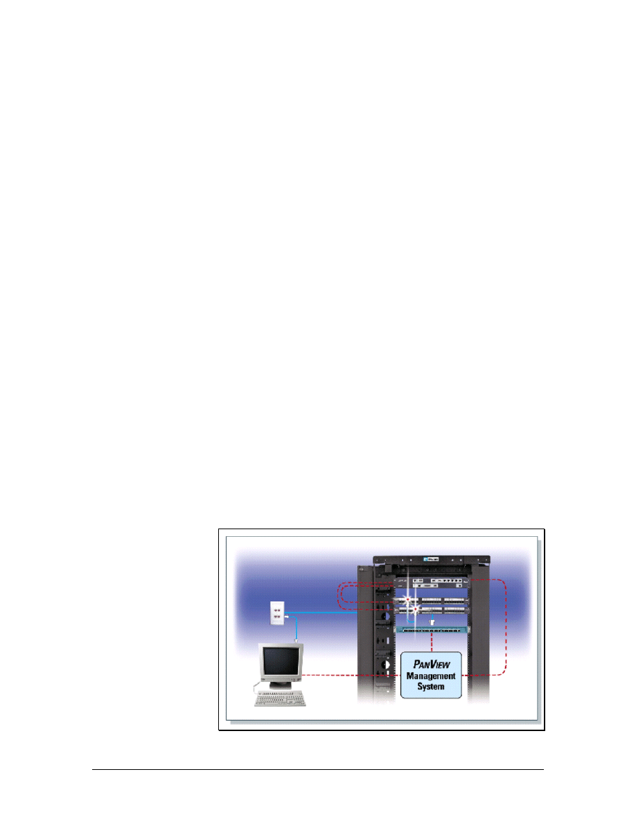
In most facilities, there is no provision to keep authorized
maintenance personnel from installing unauthorized patches or
installing an unauthorized hub into a circuit. There is an emerging
family of automated patch panels which can provide extensive
network monitoring in addition to simplifying the provisioning of
moves, adds, and changes. These patch panels normally provide an
indicator lamp over any patch cord that needs to be removed, and
then once the cord is released, provides a second light over the jack to
which they should be reaffixed. In this way the system can
automatically guide a relatively unskilled employee through moves,
adds, and changes.
The same mechanism that detects when the operator has moved a
given jack will also detect when a jack has been pulled. An
unauthorized resetting of a patch can trigger an event in the system
log, and if need be trigger an alarm. For instance, if a half-dozen
wires to the work area suddenly show up as being open at 2:30 in the
morning, this is an event worth looking into, as theft may be
occurring.
14 - 125 CCNA 1: Networking Basics v3.0 – Structured Cabling Supplement
Copyright
2003, Cisco Systems, Inc.
1.6.2 Types of patch cables
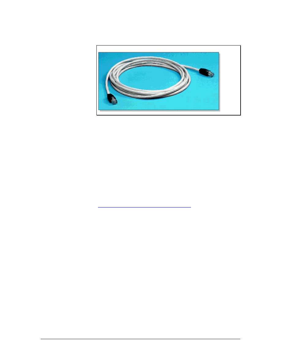
Figure 1 UTP Patch Cable
Patch cables come in a variety of wiring schemes. The straight-
through cable is the most common patch cable. It has the same wiring
scheme on both ends of the cable. Therefore, a pin on one end is
connected to the corresponding pin number on the other end. These
types of cables are used to connect PCs to a network, a hub, or a
switch.
When connecting a communications device such as a hub or switch to
an adjacent hub or switch, a crossover cable is typically used.
Crossover cables use the T568-A wiring plan on one end and T568-B
on the other end.
Lab 1: Examination of Termination Types
15 - 125 CCNA 1: Networking Basics v3.0 – Structured Cabling Supplement
Copyright
2003, Cisco Systems, Inc.
1.6.3 Cable management
Figure 1 Panduit Rack-Mounted Vertical and Horizontal Cable
Management System
Cable management devices are used to route cables along a neat and
orderly path and to assure minimum bend radius is maintained. Cable
management also simplifies cable additions and modification to the
wiring system.
There are many options for cable management in a TR. Cable baskets
can be used for easy, lightweight installations. Ladder racks are often
used to support heavy loads of bundled cable. Different types of
conduits can be used to run cable inside walls, ceilings, floors, or to
shield them from external conditions. Cable management systems are
used vertically and horizontally on telecommunications racks to
distribute cable neatly, as shown in Figure 1.
16 - 125 CCNA 1: Networking Basics v3.0 – Structured Cabling Supplement
Copyright
2003, Cisco Systems, Inc.
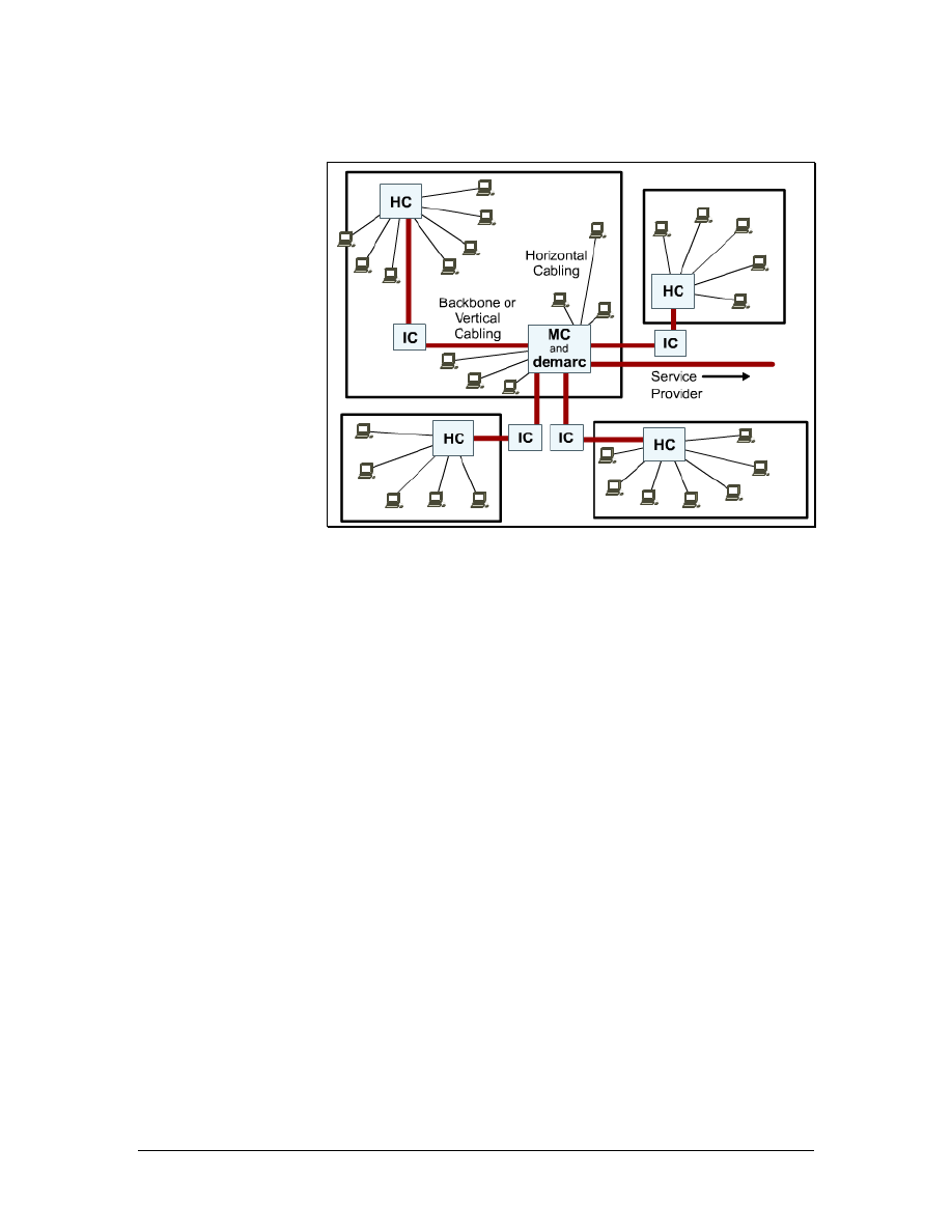
1.7 MC, IC, and HC
Figure 1 MC, HC, and IC Planning
Most networks have multiple TRs for various reasons. If a network is
spread over many floors or buildings, a TR is needed for each floor of
each building. Media can only travel a certain distance before the
signal starts to degrade or attenuate. Therefore, TRs are located at
defined distances throughout the LAN to provide interconnects and
cross-connects to hubs and switches to assure desired network
performance. These TRs house equipment such as repeaters, hubs,
bridges, or switches that are needed to regenerate the signals.
The primary TR is referred to as the main cross-connect (MC). The
MC is the center of the network. This is where all the wiring
originates and where most of the equipment is located. The
intermediate cross-connect (IC) is connected to the MC and may hold
the equipment for a building on a campus. The horizontal cross-
connect (HC) provides the cross-connect between the backbone and
horizontal cables on a single floor of a building.
17 - 125 CCNA 1: Networking Basics v3.0 – Structured Cabling Supplement
Copyright
2003, Cisco Systems, Inc.
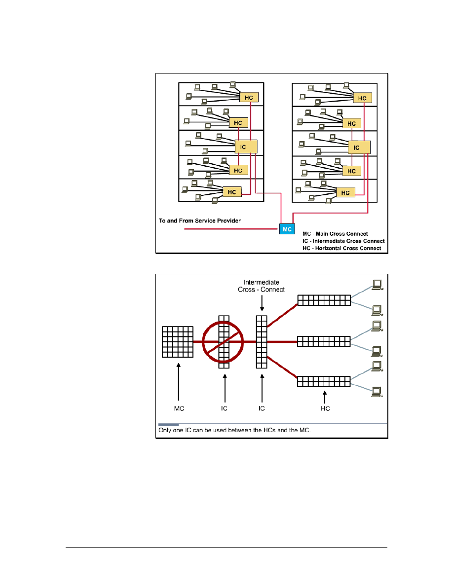
1.7.1 Main cross-connect (MC)
Figure 1 MC, HC, and IC
Figure 2 Connecting the MC to the IC and HCs
The MC is the main concentration point of a building or campus. It is
the room that controls the rest of the TRs in a location. In some
networks, it is where the cable plant connects to the outside world, or
the demarc.
All ICs and HCs are connected to the MC in a star topology.
Backbone, or vertical, cabling is used to connect ICs and HCs on
different floors. If the entire network is confined to a single multi-
18 - 125 CCNA 1: Networking Basics v3.0 – Structured Cabling Supplement
Copyright
2003, Cisco Systems, Inc.
story building, the MC is usually located on one of the middle floors,
even if the demarc is located in an entrance facility on the first floor
or in the basement.
The backbone cabling runs from the MC to each of the ICs. The red
lines in Figure 1 represent the backbone cabling. The ICs are located
in each of the campus buildings, and the HCs serve work areas. The
black lines represent horizontal cabling from the HCs to the work
areas.
For campus networks in multiple buildings, the MC is usually located
in one building. Each building typically has its own version of the
MC called the intermediate cross-connect (IC). The IC connects all
the HCs within the building. It also enables the extension of backbone
cabling from the MC to each HC because this interconnection point
does not degrade the communications signals.
As shown in Figure 2, there may only be one MC for the entire
structured cabling installation. The MC feeds the ICs. Each IC feeds
multiple HCs. There can only be one IC between the MC and any
HC.
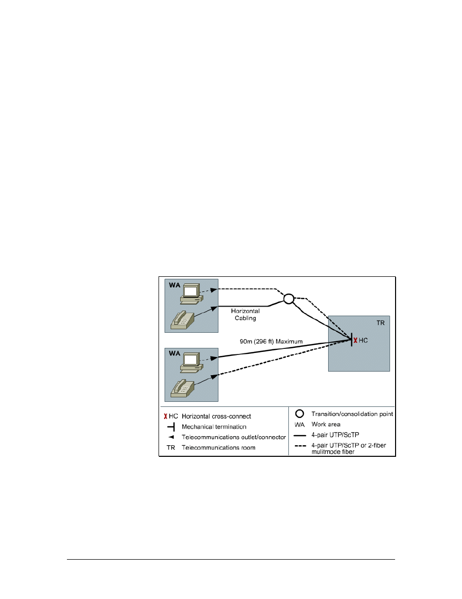
1.7.2 Horizontal cross-connect (HC)
Figure 1 Horizontal Cabling and Symbols
The horizontal cross-connect (HC) is the TR closest to the work
areas. The HC is typically a patch panel or punch down block. The
HC may also contain networking devices such as repeaters, hubs, or
switches. It can be rack mounted in a room or in a cabinet. Since a
typical horizontal cable system includes multiple cable runs to each
workstation, it can represent the largest concentration of cable in the
19 - 125 CCNA 1: Networking Basics v3.0 – Structured Cabling Supplement
Copyright
2003, Cisco Systems, Inc.

building infrastructure. A building with 1,000 workstations may
contain a horizontal cable system with 2,000 to 3,000 cable runs.
Horizontal cabling includes the copper or optical fiber networking
media that is used from the wiring closet to a workstation, as shown
in Figure 1. Horizontal cabling also includes the networking media
that runs along a horizontal pathway that leads to the
telecommunications outlet, and the patch cords, or jumpers in the HC.
Any cabling between the MC and another TR is backbone cabling.
The difference between horizontal and backbone cabling is defined in
the standards.
Lab 2: Terminating a Category 5e Cable on a Category 5e Patch
Panel
1.7.3 Backbone cabling
Any cabling installed between the MC and another TR is known as
backbone cabling. The difference between horizontal and backbone
cabling is clearly defined in the standards. Backbone cabling is also
referred to as vertical cabling. It consists of backbone cables,
intermediate and main cross-connects, mechanical terminations, and
patch cords or jumpers used for backbone-to-backbone cross-
connection. Backbone cabling includes the following:
• TRs on the same floor, MC to IC, and IC to HC
• Vertical connections, or risers, between TRs on different
floors, such as MC to IC cabling
• Cables between TRs and demarcation points
• Cables between buildings, or inter-building cables, in a multi-
building campus
The maximum distance for cabling runs depends on the type of cable
installed. For backbone cabling, the maximum distance can also be
affected by how the cabling will be used. For example, if single-mode
fiber-optic cable will be used to connect the HC to the MC, then the
maximum distance for the backbone cabling run is 3000 m (9842.5
feet).
Sometimes the maximum distance of 3000 m (9842.5 feet) must be
split between two sections. For example, if the backbone cabling will
connect the HC to an IC and the IC to the MC. When this occurs, the
maximum distance for the backbone cabling run between the HC and
the IC is 300 m (984 feet). The maximum distance for the backbone
cabling run between the IC and the MC is 2700 m (8858 feet).
20 - 125 CCNA 1: Networking Basics v3.0 – Structured Cabling Supplement
Copyright
2003, Cisco Systems, Inc.
1.7.4 Fiber-optic backbone
The use of fiber optics is an effective way to move backbone traffic
for three reasons:
• Optical fibers are impervious to electrical noise and radio
frequency interference.
• Fiber does not conduct currents that can cause ground loops.
• Fiber-optic systems have high bandwidth and can work at
high speeds.
A fiber-optic backbone can also be upgraded to provide even greater
performance when the terminal equipment is developed and becomes
available. This can make fiber optics very cost effective.
An additional advantage is that fiber can travel much farther than
copper when used as a backbone media. Multimode optical fiber can
cover lengths of up to 2000 meters (6561.7 feet). Single-mode fiber-
optic cables can cover up to 3000 meters (9842.5 feet). Optical fiber,
especially single mode fiber, can carry signals much farther.
Distances of 96.6 to 112.7 km (60 to 70 miles) are possible,
depending on terminal equipment. However, these longer distances
are beyond the scope of the LAN standards.
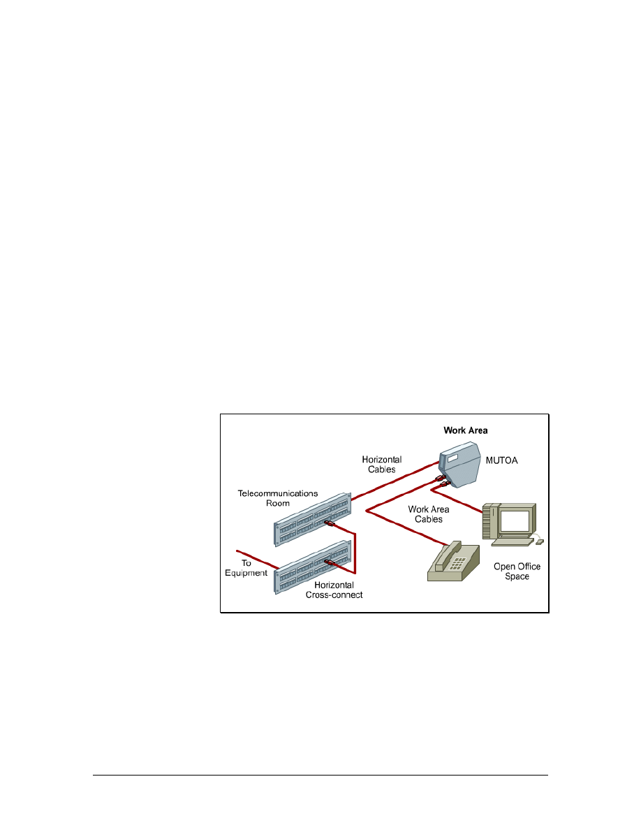
1.7.5 MUTOAs and Consolidation Points
Figure 1 Typical MUTOA Installation
21 - 125 CCNA 1: Networking Basics v3.0 – Structured Cabling Supplement
Copyright
2003, Cisco Systems, Inc.
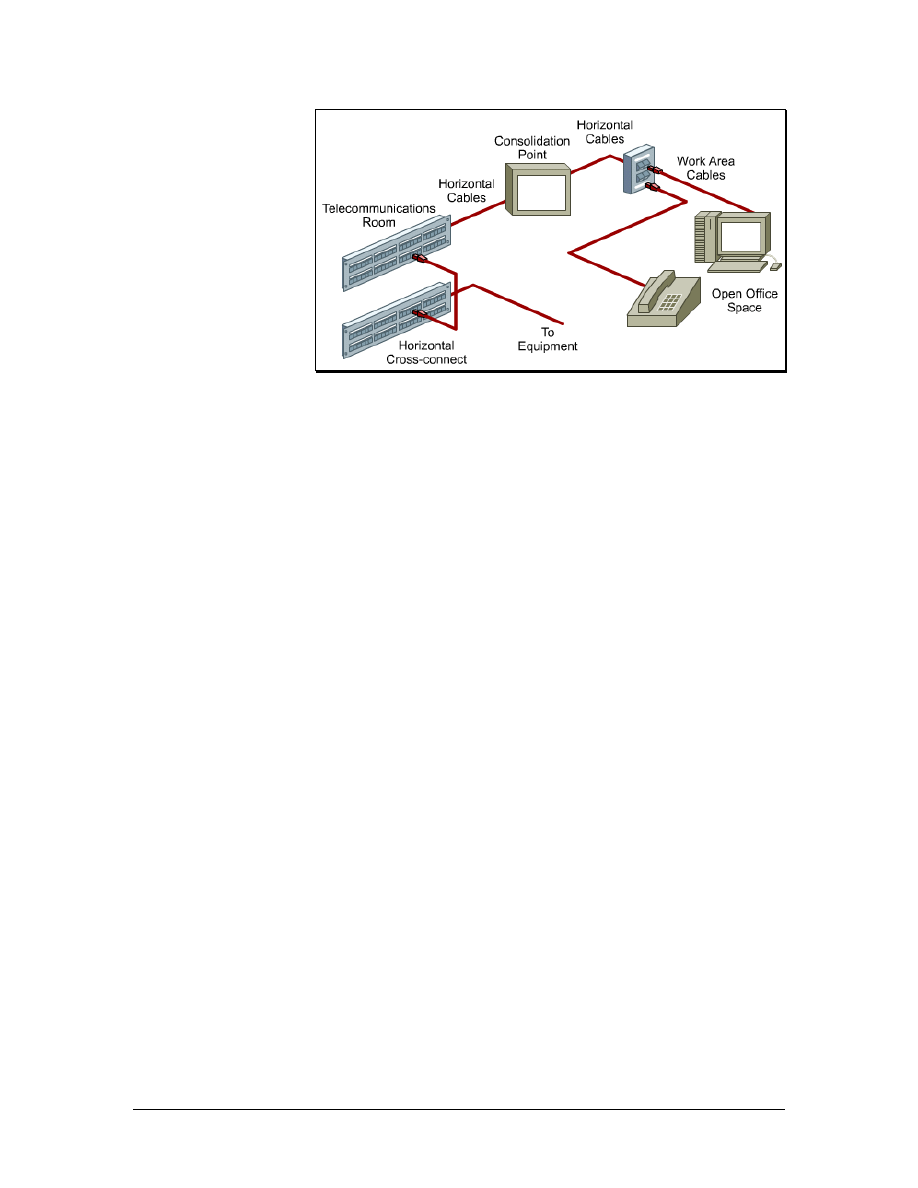
Figure 2 Typical Consolidation Point Installation
Additional specifications for horizontal cabling in work areas with
moveable furniture and partitions have been included in TIA/EIA-
568-B.1. Horizontal cabling methodologies using multiuser
telecommunications outlet assemblies (MUTOAs) and consolidation
points (CPs) are specified for open office environments. These
methodologies provide increased flexibility and economy for
installations that require frequent reconfiguration.
Rather than replacing the entire horizontal cabling system feeding
these areas, a CP or MUTOA can be located close to the open office
area and eliminate the need to replace the cabling all the way back to
the TR whenever the furniture is rearranged. The cabling only needs
to be replaced between the new work area outlets and the CP or
MUTOA. The longer distance of cabling back to the TR remains
permanent.
A MUTOA is a device that allows users to move, add devices, and
make changes in modular furniture settings without re-running the
cable. Patch cords can be routed directly from a MUTOA to work
area equipment, as shown in Figure 1. A MUTOA location must be
accessible and permanent. A MUTOA cannot be mounted in ceiling
spaces or under access flooring. It cannot be mounted in furniture
unless the furniture is permanently secured to the building structure.
The TIA/EIA-568-B.1 standard includes the following guidelines for
MUTOAs:
• At least one MUTOA is needed for each furniture cluster.
• A maximum of 12 work areas can be served by each
MUTOA.
• Patch cords at work areas should be labeled on both ends
with unique identifiers.
• The maximum patch cord length is 22 m (72.2 feet).
22 - 125 CCNA 1: Networking Basics v3.0 – Structured Cabling Supplement
Copyright
2003, Cisco Systems, Inc.

Consolidation points (CPs) provide limited area connection access.
Permanent flush wall-mounted, ceiling-mounted, or support column-
mounted panels are generally used in modular furniture work areas.
These panels must be unobstructed and fully accessible without
moving fixtures, equipment, or heavy furniture. Workstations and
other work area equipment do not plug into the CP like they do with
the MUTOA, as shown in Figure 2. Workstations plug into an outlet,
which is then connected to the CP.
The TIA/EIA-569 standard includes the following guidelines for CPs:
• At least one CP is needed for each furniture cluster
• Each CP can serve a maximum of 12 work areas
• The maximum patch cord length is 5 m (16.4 feet)
For both consolidation points and MUTOAs, TIA/EIA-568-B.1
recommends a separation of at least 15 m (49 feet) for equipment
between the TR and the CP or MUTOAs. This is to avoid problems
with crosstalk and return loss.
23 - 125 CCNA 1: Networking Basics v3.0 – Structured Cabling Supplement
Copyright
2003, Cisco Systems, Inc.

2 Structured Cabling Standards and
Codes
Standards are sets of rules or procedures that are either widely used,
or officially specified to provide a model of excellence. A single
vendor specifies some standards. Industry standards support multi-
vendor interoperability in the following ways:
• Standardized media and layout descriptions for both
backbone and horizontal cabling
• Standard connection interfaces for the physical connection of
equipment
• Consistent and uniform design that follows a system plan and
basic design principles
Numerous organizations regulate and specify different types of
cables. Local, state, county, and national government agencies also
issue codes, specifications, and requirements.
A network that is built to standards should work well, or interoperate,
with other standard network devices. The long term performance and
investment value of many network cabling systems has been
diminished by installers who do not comply with mandatory and
voluntary standards.
These standards are constantly reviewed and periodically updated to
reflect new technologies and the increasing requirements of voice and
data networks. As new technologies are added to the standards, others
are phased out. A network may include technologies that are no
longer a part of the current standard or will soon be eliminated. These
technologies do not usually require an immediate changeover. They
are eventually replaced by newer and faster technologies.
Many international organizations attempt to develop universal
standards. Organizations such as the IEEE, ISO, and IEC are
examples of international standards bodies. These organizations
include members from many nations, which all have their own
process for creating standards.
In many countries, the national codes become the model for state and
provincial agencies as well as municipalities and other governmental
units to incorporate into their laws and ordinances. The enforcement
then moves to a local authority. Always check with local authorities
to determine what codes are enforced. Most local codes take
precedence over national codes, which take precedence over
international codes.
24 - 125 CCNA 1: Networking Basics v3.0 – Structured Cabling Supplement
Copyright
2003, Cisco Systems, Inc.
2.1 Telecommunications Industry Association (TIA)
and Electronic Industries Alliance (EIA)
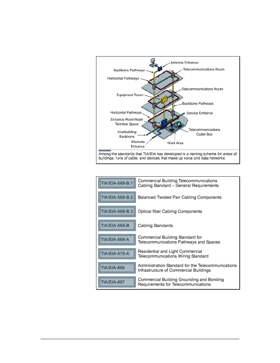
Figure 1 TIA/EIA Standards for buildings
Figure 2 TIA/EIA Structured Cabling Standards
The Telecommunications Industry Association (TIA) and Electronic
Industries Alliance (EIA) are trade associations that develop and
publish a series of standards covering structured voice and data
wiring for LANs. These standards are shown in Figure 1.
25 - 125 CCNA 1: Networking Basics v3.0 – Structured Cabling Supplement
Copyright
2003, Cisco Systems, Inc.

Both TIA and EIA are accredited by the American National
Standards Institute (ANSI) to develop voluntary telecommunication
industry standards. Many standards are labeled ANSI/TIA/EIA. The
various committees and subcommittees of TIA/EIA develop
standards for fiber optics, user premise equipment, network
equipment, wireless communications, and satellite communications.
TIA/EIA standards
While there are many standards and supplements, the following are
used most frequently by cable installers and are listed in Figure 2:
• TIA/EIA-568-A – This former Commercial Building
Standard for Telecommunications Wiring specified
minimum requirements for telecommunications cabling,
recommended topology and distance limits, media and
connecting hardware performance specifications, and
connector and pin assignments.
• TIA/EIA-568-B – The current Cabling Standard specifies
the component and transmission requirements for
telecommunications media. The TIA/EIA-568-B standard is
divided into three separate sections: 568-B.1, 568-B.2, and
568-B.3.
TIA/EIA-568-B.1 specifies a generic
telecommunications cabling system for commercial
buildings that will support a multiproduct,
multivendor environment.
TIA/EIA-568-B.1.1 is an addendum that applies to
4-pair UTP and 4-pair screened twisted-pair (ScTP)
patch cable bend radius.
TIA/EIA-568-B.2 specifies cabling components,
transmission, system models, and the measurement
procedures needed for verification of twisted pair
cabling.
TIA/EIA-568-B.2.1 is an addendum that specifies
the requirements for Category 6 cabling.
TIA/EIA-568-B.3 specifies the component and
transmission requirements for an optical fiber
cabling system.
• TIA/EIA-569-A – The Commercial Building Standard for
Telecommunications Pathways and Spaces specifies design
and construction practices within and between buildings that
support telecommunications media and equipment.
• TIA/EIA-606-A – The Administration Standard for the
Telecommunications Infrastructure of Commercial Buildings
includes standards for labeling cables. This standard
specifies that each hardware termination unit should have a
26 - 125 CCNA 1: Networking Basics v3.0 – Structured Cabling Supplement
Copyright
2003, Cisco Systems, Inc.

unique identifier. It also outlines the requirements for record
keeping and maintaining documentation for administering
the network.
• TIA/EIA-607-A – The standard for Commercial Building
Grounding and Bonding Requirements for
Telecommunications supports a multivendor, multiproduct
environment, as well as the grounding practices for various
systems that may be installed on customer premises. The
standard specifies the exact interface points between the
building grounding systems and the telecommunications
equipment grounding configuration. The standard also
specifies the building grounding and bonding configurations
needed to support this equipment.
Web Link:
2.2 European Committee for Electrotechnical
Standardization (CENELEC)
The European Committee for Electrotechnical Standardization
(CENELEC) was established as a non-profit organization under
Belgian Law in 1973. CENELEC develops electrotechnical standards
for most of Europe. CENELEC works with 35,000 technical experts
from 22 European countries to publish standards for the European
market. It is officially recognized as the European standards
organization in Directive 83/189/EEC of the European Commission.
Many CENELEC cabling standards are the same as ISO cabling
standards, with some minor changes.
CENELEC and the International Electrotechnical Commission (IEC)
operate at two different levels. However, their actions have a strong
mutual impact. They are the most important standardization bodies in
the electrotechnical field in Europe. Cooperation between CENELEC
and the IEC is described in the Dresden Agreement. This agreement
was approved and signed by both partners in the German city of
Dresden in 1996. This agreement was intended to accomplish the
following:
• Expedite the publication and common adoption of
international standards
• Accelerate the standards preparation process in response to
market demands
• Ensure rational use of available resources
Therefore, full technical consideration of the standards should
preferably take place at an international level.
27 - 125 CCNA 1: Networking Basics v3.0 – Structured Cabling Supplement
Copyright
2003, Cisco Systems, Inc.

Web Link:
2.3 International Organization for Standardization
(ISO)
International Organization for Standardization (ISO) consists of
national standards organizations from over 140 countries, including
ANSI. ISO is a nongovernmental organization that promotes the
development of standardization and related activities. The work of the
ISO results in international agreements, which are published as
international standards.
ISO has defined several important computer standards. The most
significant standard may be the Open Systems Interconnection (OSI)
model, a standardized architecture for network design.
Web Link:
http://www.iso.org/iso/en/ISOOnline.frontpage
2.4 U.S. Codes
Some networking projects require a permit to ensure that the work is
done properly. Contact local zoning departments for information on
permit requirements.
To obtain copies of local or state building codes, contact the building
official for the jurisdiction. All the basic building codes throughout
the United States can be purchased from the International Conference
of Building Officials (ICBO). Basic building codes include CABO,
ICBO, BOCA, SBCCI, and ICC.
Note: The Americans with Disabilities Act (ADA) has led to several
important changes in construction, alteration, and renovation guidelines
in regards to networking and telecommunications. These requirements
depend on the use of the facility and fines can be assessed for failure to
comply.
Many codes that require local inspection and enforcement are
incorporated into state or provincial governments and then transferred
to city and county enforcement units. This includes building, fire, and
electrical codes. Like occupational safety, these were originally local
issues, but disparity of standards and a lack of enforcement have led
to national standards.
The enforcement of some codes will vary by city, county, or state.
Projects within a city are generally handled by city agencies, while
28 - 125 CCNA 1: Networking Basics v3.0 – Structured Cabling Supplement
Copyright
2003, Cisco Systems, Inc.
those outside the city are covered by county agencies. Fire codes may
be enforced by county building permit departments in some
communities but by local fire departments in others. Violating these
codes can result in expensive penalties and delayed project costs.
Local entities inspect and enforce most codes, but the organizations
that make the standards will usually write them. The National
Electrical Code (NEC) is written to sound like a legal ordinance. This
allows local governments to adopt the code by vote. This may not
happen regularly, so it is important to know which version of the
NEC is used in the area where the cabling is installed.
Note that most countries have similar systems of codes. Knowledge
of these local codes is important for planning a project that crosses
national boundaries.
Web Link:
2.5 Evolution of Standards
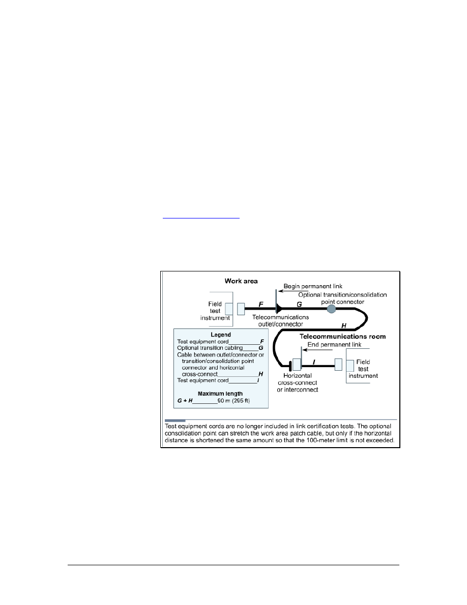
Figure 1 Changes to Horizontal Cabling Standards
When network bandwidth increased from 10 Mbps to over 1000
Mbps, it created new demands for cabling. Many types of older cable
are inadequate for use in faster, modern networks. Therefore, cabling
will usually change over time. The following TIA/EIA-568-B.2
standards reflect this.
For twisted-pair cables, only 100-ohm Category 3, 5e, and 6 cables
are recognized. Category 5 cable is no longer recommended for new
29 - 125 CCNA 1: Networking Basics v3.0 – Structured Cabling Supplement
Copyright
2003, Cisco Systems, Inc.

installations, and has been moved from the body of the standard to the
appendix. Category 5e or greater is now the recommended cable for
100-ohm twisted pair.
The Category 6 standard specifies performance parameters that will
ensure that products meeting the standard will be component
compliant, backward compatible, and interoperable between vendors.
When terminating Category 5e and higher cables, the pairs should not
be untwisted more than 13 mm (0.5 inch) from the point of
termination. The minimum bend radius for UTP horizontal cabling
remains four times the cable diameter. The minimum bend radius for
UTP patch cable is now equal to the cable diameter. UTP patch cable
contains stranded wires. Therefore, it is more flexible than the solid
core copper cables used in horizontal cabling.
The acceptable length of patch cords in the telecommunications room
has changed from a maximum length of 6 m (19.7 feet) to 5 m (16.4
feet). The maximum acceptable length of a jumper cable in the work
area has changed from 3 m (9.8 feet) to 5 m (16.4 feet). The
maximum horizontal segment distance is still 90 m (295 feet). If a
MUTOA is used, the work area jumper length can be increased if the
horizontal length is decreased for a maximum total link segment
length of 100 m (328 feet). These standards are shown in Figure 1.
The use of a MUTOA or Consolidation Point also mandates a
separation of at least 15 meters (49 ft) between the TR and the
MUTOA or Consolidation Point in order to limit problems with
crosstalk and return loss.
In the past, all patch cords and cross-connect jumpers had to use
stranded cable for the flexibility needed to survive repeated
connection and reconnection. This standard now says that stranded
conductors should be used. This allows for solid conductor cord
designs.
Patch cords are critical elements in a network system. The onsite
manufacturing of patch cords and jumpers is still permitted. However,
network designers are strongly encouraged to purchase cables that are
premade and tested.
Category 6 and the emerging Category 7 are the newest copper cables
available. As Category 6 cable is used more frequently, it is important
for cable installers to understand its benefits.
The main difference between Category 5e and Category 6 is the way
that spacing between the pairs inside the cables is maintained. Some
Category 6 cables use a physical divider down the center of the cable.
Others have a unique sheath that locks the pairs into position.
Another type of Category 6 cable, which is often referred to as ScTP,
uses a foil screen that over wraps the pairs in the cable.
To achieve even greater performance than Category 6 and the
proposed Category 7, cables use a fully-shielded construction, which
30 - 125 CCNA 1: Networking Basics v3.0 – Structured Cabling Supplement
Copyright
2003, Cisco Systems, Inc.

limits crosstalk between all pairs. Each pair is enveloped within a foil
wrap and an overall braided sheath surrounds the four foil-wrapped
pairs. A drain wire may be provided in future cables to facilitate
grounding.
Standards for the structured cabling will continue to evolve. The
focus will be on supporting the new technologies that are converging
on the data network, such as the following:
■
IP telephony and Wireless utilizing a power signal in the
transmission to provide power to the IP Phones or Access Points.
■
Storage Area Networking (SAN) utilizing 10GB Ethernet
transmission
■
Metro Ethernet “last mile” solutions that require optimizing
bandwidth and distance requirements
The standard for Power over Ethernet (PoE) is under development
and will be available in the near future. PoE embeds a power signal
on cables used for Ethernet transmissions. This power signal is used
to free IP phones and wireless access points from the need for
connection to AC power outlets, simplifying deployment and
reducing costs.
31 - 125 CCNA 1: Networking Basics v3.0 – Structured Cabling Supplement
Copyright
2003, Cisco Systems, Inc.

3 Safety
3.1 Safety Codes and Standards for the United
States
Most nations have rules designed to protect workers against
hazardous conditions. In the United States, the organization in charge
of worker safety and health is the Occupational Safety and Health
Administration (OSHA). Since the agency was created in 1971,
workplace fatalities have been cut in half and occupational injury and
illness rates have declined 40 percent. At the same time, U.S.
employment has nearly doubled from 56 million workers at 3.5
million worksites to 105 million workers at nearly 6.9 million sites.
OSHA is responsible for enforcing U.S. labor laws to protect
workers. OSHA is not a building code or building permit related
agency. However, OSHA inspectors can impose heavy fines or shut
down a jobsite if they find serious safety violations. Anyone who
works on, or is responsible for, a construction site or business facility
must be familiar with OSHA regulations. The organization offers
safety information, statistics, and publications on its website.
3.1.1 MSDS
A material safety data sheet (MSDS) is a document that contains
information about the use, storage, and handling of a hazardous
material. An MSDS provides detailed information about the potential
health effects of exposure and how to work safely with the material. It
includes the following information:
•
What the hazards of the material are
•
How to use the material safely
•
What to expect if the recommendations are not
followed
•
What to do if accidents occur
•
How to recognize symptoms of overexposure
•
What to do if such incidents occur
Web Link:
3.1.2 Underwriters Laboratories (UL)
Underwriters Laboratories (UL) is an independent, nonprofit product
safety testing and certification organization. UL has tested products
for public safety for over a century. The UL focuses on safety
standards, but has expanded its certification program to evaluate
twisted-pair LAN cables for performance. This evaluation is based on
32 - 125 CCNA 1: Networking Basics v3.0 – Structured Cabling Supplement
Copyright
2003, Cisco Systems, Inc.
IBM and TIA/EIA performance specifications, as well as NEC safety
specifications. The UL also established a program to mark shielded
and unshielded twisted-pair LAN cables. This should simplify the
process of ensuring that the materials used in an installation meet the
specifications.
UL initially tests and evaluates samples of cable. After granting a UL
listing, the organization conducts follow-up tests and inspections.
This testing process makes the UL mark a valuable symbol to buyers.
The UL LAN Certification Program addresses safety and
performance. Companies with cables that earn the UL markings
display them on the outer jacket. For example, Level I, LVL I, or
LEV I.
Web Link:
3.1.3 National Electrical Code (NEC)
The purpose of the National Electrical Code (NEC) is to safeguard
people and property from hazards that arise from the use of
electricity. The National Fire Protection Association (NFPA)
sponsors this code with support from ANSI. The code is revised
every three years.
Several organizations, including UL, have established standards for
flame and smoke that apply to network cables in buildings. However,
the NEC standards are more widely supported by local licensing and
inspection officials.
3.1.4 The NEC Type Codes
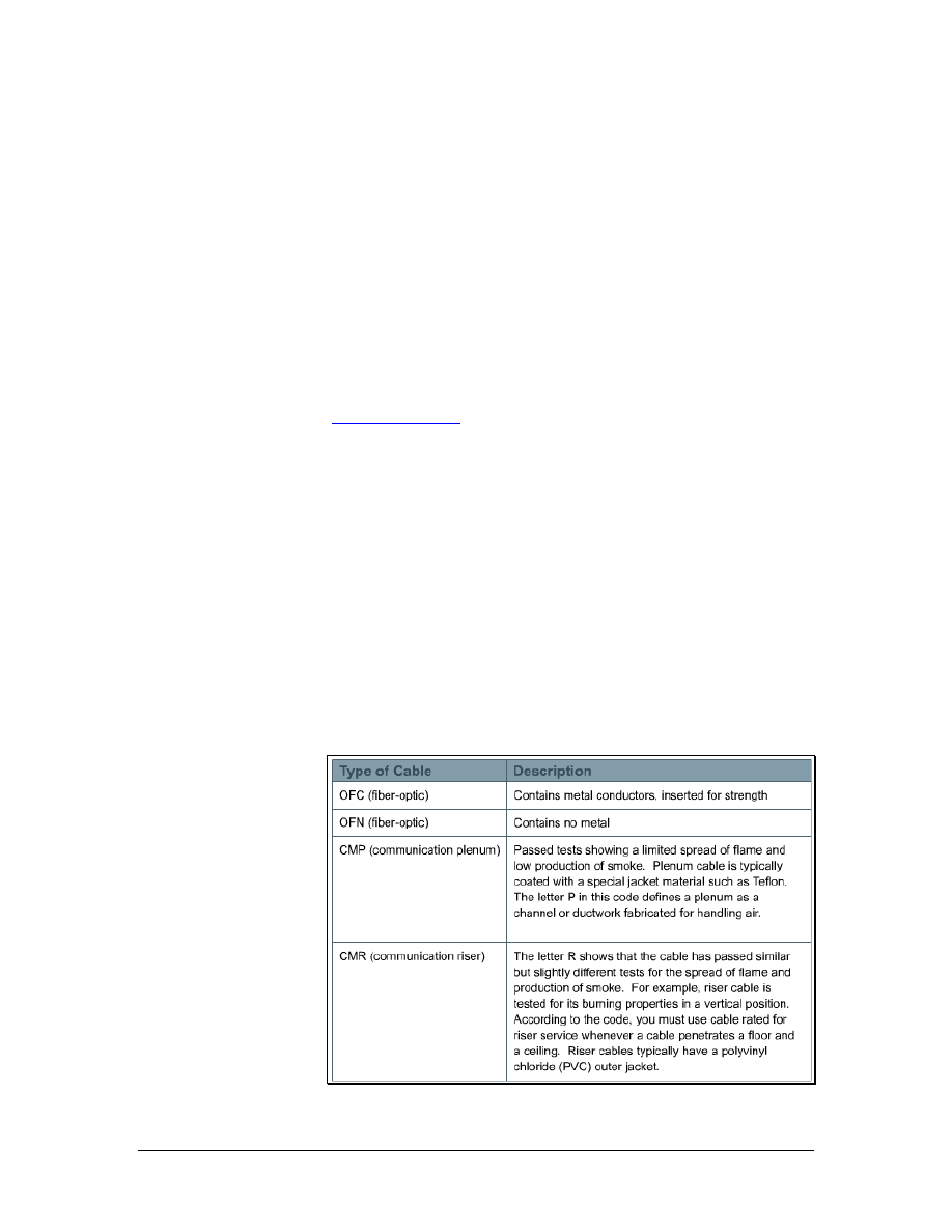
Figure 1 NEC Cable Type Codes
33 - 125 CCNA 1: Networking Basics v3.0 – Structured Cabling Supplement
Copyright
2003, Cisco Systems, Inc.

NEC type codes are listed in catalogs of cables and supplies. These
codes classify products for specific uses, as shown in Figure 1.
Interior network cables are generally listed in the CM category for
communications or MP for multipurpose. Some companies choose to
run their cables through the test process as remote control or power-
limited circuit cables class 2 (CL2) or class 3 (CL3) general tests
instead of through the CM or CP tests. However, the flame and
smoke criteria are generally the same for all tests. The differences
between these markings concern the amount of electrical power that
could run through the cable in the worst case. The MP cable is
subjected to tests that assume the most power-handling capability.
CM, CL3, and CL2 go through tests with decreasing levels of power
handling.
Web Link:
http://www.nfpa.org/Home/index.asp
3.2 Safety Around Electricity
In addition to learning about safety organizations, cable installers
should also learn about basic safety principles. These principles will
be used every day on the job and are necessary for the curriculum
labs. Since there are many hazards involved in cable installation, the
installer should be prepared for all situations to prevent accidents or
injuries.
3.2.1 High-voltage
Cable installers work with wiring designed for low-voltage systems.
Most people would not notice the voltage applied to a data cable.
However, the voltage of network devices that data cables plug into
can range from 100 to 240 volts in North America. If a circuit failure
made the voltage accessible, it could cause a dangerous or fatal shock
to the installer.
Low-voltage installers must also consider the hazards of high-voltage
wiring. Dangerous shocks may occur if insulation is inadvertently
removed from existing high-voltage wiring. After coming in contact
with high-voltage, installers may be unable to control their muscles or
pull away.
3.2.2 Lightning and high-voltage danger
High-voltage is not limited to power lines. Lightning is another
source of high-voltage. Lightning can be fatal or damage network
equipment. Therefore, it is important to prevent lightning from
entering the network cabling.
34 - 125 CCNA 1: Networking Basics v3.0 – Structured Cabling Supplement
Copyright
2003, Cisco Systems, Inc.

The following precautions should be taken to avoid personal injury
and network damage from lightning and electrical shorts:
• All outside wiring must be equipped with properly grounded
and registered signal circuit protectors at the point where they
enter the building, or the entrance point. These protectors
must be installed in compliance with local telephone
company requirements and applicable codes. Telephone wire
pairs should not be used without authorization. If
authorization is obtained, do not remove or modify telephone
circuit protectors or grounding wires.
• Never run wiring between structures without proper
protection. In fact, protection from lighting effects is
probably one of the biggest advantages of using fiber optics
between buildings.
• Avoid installing wires in or near damp locations.
• Never install or connect copper wiring during electrical
storms. Improperly protected copper wiring can carry a fatal
lightning surge for many miles.
3.2.3 High-voltage safety test
Voltage is invisible. However, the effects of voltage are seen when
equipment malfunctions or someone gets shocked.
When working with anything that plugs into a wall for power, check
for voltage on surfaces and devices before coming in contact with
them. Use a known reliable voltage measurement device such as a
multimeter or voltage detector. Take measurements immediately
before work begins each day. Measure again after a break on any job.
Recheck the measurements again when finished.
Lightning and static electricity cannot be predicted. Never install or
connect copper wiring during electrical storms. Copper wiring can
carry a fatal lightning surge for many kilometers. This is important to
consider for external wiring between buildings or underground
wiring. All outside wiring should be equipped with properly
grounded and approved signal circuit protectors. These protectors
must be installed in compliance with the local codes. In most cases,
the local codes will align with national codes.
3.2.4 Grounding
Grounding provides a direct path to the earth for voltage. Equipment
designers isolate the circuits in equipment from the chassis. The
chassis is the box where the circuits are mounted. Any voltage that
leaks from the equipment to its chassis should not stay in the chassis.
Grounding equipment conducts any stray voltage to the earth without
harming the equipment. Without a proper path to ground, stray
voltage may use a different path, such as a human body.
35 - 125 CCNA 1: Networking Basics v3.0 – Structured Cabling Supplement
Copyright
2003, Cisco Systems, Inc.
The grounding electrode is the metal rod that is buried in the ground
near the entrance point of the building. For years, cold water pipes
that entered the building from underground water mains were
considered good grounds. Large structural members, such as I-beams
and girders, were also acceptable. Although these may provide an
adequate path to ground, most local codes now require a dedicated
grounding system. Grounding conductors connect equipment to
grounding electrodes.
Be aware of the grounding system in the lab and on each job site.
Verify that the grounding system works. Grounding is often installed
incorrectly. Some installers take shortcuts to accomplish a technically
adequate ground in a nonstandard way. Changes to other parts of the
network or to the building may destroy or eliminate a nonstandard
ground system. This would leave the equipment and people at risk.
3.2.5 Bonding
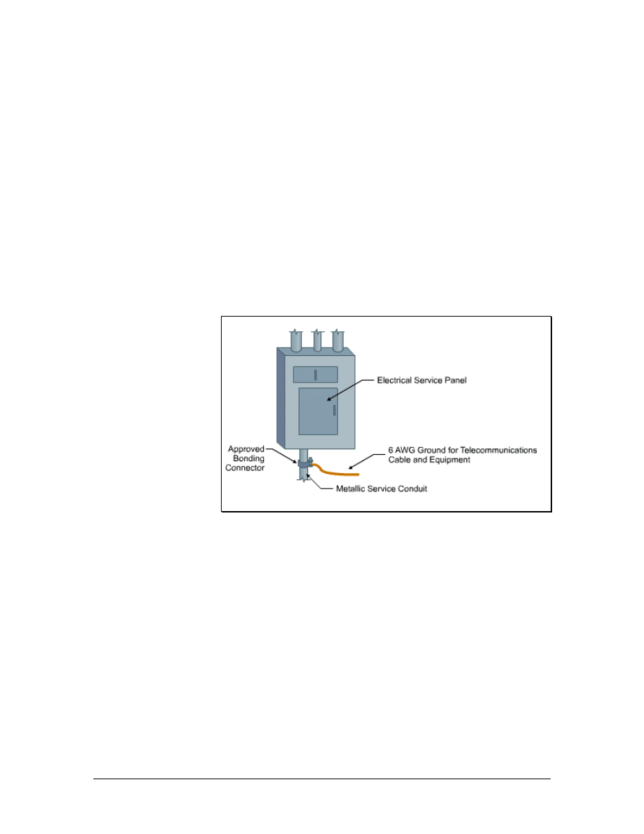
Figure 1 Bonding
Bonding allows various wiring fixtures to interconnect with the
grounding system, as shown in Figure 1. Bonding is an extension of
ground wiring. A device such as a switch or router may have a
bonding strap between its case and a ground circuit to ensure a good
connection.
Properly installed bonding and grounding will accomplish the
following:
• Minimize electrical surge or spike effects
• Maintain the integrity of the electrical grounding plant
• Provide a safer and more effective path to ground
36 - 125 CCNA 1: Networking Basics v3.0 – Structured Cabling Supplement
Copyright
2003, Cisco Systems, Inc.

Telecommunications bonds are typically used in the following:
• Entrance facilities
• Equipment rooms
• Telecommunications rooms
3.2.6 Grounding and bonding standards
The National Electrical Code contains much information on
grounding and bonding. The TIA/EIA standard on Grounding and
Bonding, TIA/EIA-607-A, Commercial Building Grounding and
Bonding Requirements for Telecommunications, extends grounding
and bonding into the telecommunications structured cabling system.
TIA/EIA-607-A specifies the exact interface points between the
grounding system of a building and the telecommunication equipment
grounding configuration. It supports a multivendor, multiproduct
environment for the grounding practices for various systems that may
be installed on customer premises. It also specifies the necessary
grounding and bonding configurations needed in the building to
support this equipment.
Web Link:
3.3 Lab and Workplace Safety Practices
Although cable installation is generally a safe profession, there are
plenty of opportunities for injury. Many injuries are caused when
installers come in contact with stray sources of voltage, or foreign
voltages. Foreign voltages include lightning, static electricity, and
voltages caused by installation faults or induction currents on network
cables.
When working in walls, ceilings, or attics, first turn off power to all
circuits that pass through those work areas. If it is not clear which
wires pass through the section of the building being worked in, shut
off all power. Never touch power cables. Even if all power to the area
has been shut off, there is no way to know if circuits are still live.
Most countries have agencies that develop and administer safety
standards. Some standards are designed to ensure public safety while
others protect the worker. Standards that protect the worker usually
cover laboratory safety, general workplace safety, compliance with
environmental regulations, and hazardous waste disposal.
37 - 125 CCNA 1: Networking Basics v3.0 – Structured Cabling Supplement
Copyright
2003, Cisco Systems, Inc.

3.3.1 Workplace safety
The following are guidelines for keeping a workplace safe:
• Before beginning work, learn the locations of all fire
extinguishers in the area. A small fire can get out of control if
unable locate an extinguisher quickly.
• Always determine the local codes in advance. Some building
codes may prohibit drilling or cutting holes in certain areas
such as firewalls or ceilings. The site administrator or facility
engineer will be able to help identify which areas are off
limits.
• When installing cable between floors, use a riser-rated cable.
Riser cable is covered with a flame retardant fluorinated
ethylene propylene (FEP) jacket to prevent flames from
reaching another floor through the cable.
• Outdoor cables typically have a polyethylene jacket.
Polyethylene burns readily and gives off dangerous gases.
NEC codes state that polyethylene building entrance cables
cannot be exposed more than 15 m (49.2 feet) into a building.
If greater distances are required, the cable must be in metallic
conduits.
• The building maintenance engineer should be consulted to
determine if there is asbestos, lead, or PCB in the work area.
If so, follow all government regulations in dealing with
hazardous materials. Do not risk personal health by working
unprotected in these areas.
• If cable must be routed through spaces where air is circulated,
be sure to use a fire-rated, or plenum-rated, cable. The most
common plenum cables are jacketed with Teflon or Halar.
Plenum grade cable does not give off poisonous gases when
it burns like regular cables, which have a polyvinyl chloride
(PVC) jacket.
3.3.2 Ladder safety
Ladders come in many sizes and shapes for specific tasks. They can
be made of wood, aluminum, or fiberglass and designed for either
light or industrial use. The two most common types are straight
ladders and stepladders. Regardless of the type or construction, make
sure the ladder is certified, and complies with ANSI specifications
and UL standards.
Select the right ladder for the job. The ladder should be long enough
to work from comfortably and sturdy enough to withstand repeated
use. Fiberglass ladders are most commonly used in cable installation.
Aluminum ladders weigh less, but they are also less stable and should
never be used around electricity. When working near electricity,
fiberglass ladders should always used.
38 - 125 CCNA 1: Networking Basics v3.0 – Structured Cabling Supplement
Copyright
2003, Cisco Systems, Inc.

Inspect the ladder first. Any ladder can develop a problem that makes
it unsafe. Inspect ladders for loose or damaged rungs, steps, rails, or
braces. Make sure that the spreaders on stepladders can be locked in
place and that the ladder has safety feet. Safety feet provide extra
stability and reduce the chances of the ladder slipping while working.
Never use a defective ladder.
Stepladders should be fully opened with the hinges locked. Straight
ladders should be placed at a four-to-one ratio. This means the base of
the ladder should be 0.25 m (10 inches) away from the wall or other
vertical surface for every 1 m (3.3 feet) of height to the point of
support. Secure a straight ladder as close to the point of support as
possible to prevent shifting. Ladders should always be placed on a
solid, level surface.
Never climb higher than the second step from the top on a stepladder,
or the third from the top on a straight ladder.
Cordon off the work area with appropriate markers such as traffic
cones or caution tape. Post signs so that people are aware of the
ladder. Lock or block any nearby doors that may come in contact with
the ladder.
3.3.3 Fiber-optic safety
Since fiber-optic cable contains glass, it is important to take
appropriate precautions. The scrap material is sharp and must be
disposed of properly. If broken, tiny slivers can be lodged into the
skin.
These rules should be followed to avoid injury when working with
fiber optics:
• Always wear safety glasses with side shields.
• Place a mat or piece of adhesive on the table so that all glass
shards that fall are easily identified.
• Do not touch eyes or contact lenses while working with fiber-
optic systems until hands have been thoroughly cleaned.
• Put all cut fiber pieces in a safe place and dispose of them
properly.
• Use a piece of adhesive or masking tape to remove any
material that gets on clothing. Use tape to remove shards
from fingers and hands.
• Do not bring food or beverages in the work area.
• Do not look directly into the end of fiber cables. Some laser
driven devices could cause irreversible damage to the eye.
39 - 125 CCNA 1: Networking Basics v3.0 – Structured Cabling Supplement
Copyright
2003, Cisco Systems, Inc.

3.3.4 Fire extinguisher use
Never attempt to fight a fire without knowing how to use a fire
extinguisher. Read the instructions and check the valve. In the United
States, fire extinguishers used in commercial buildings must be
checked at regular intervals. If they are not in good working order,
they must be replaced.
Note If someone catches on fire, remember the tip, Stop, Drop, and Roll.
Do not run. Fire spreads quickly if a burning person starts running. If
a burning person panics and runs down the hall, tackle that person.
Drop to the floor and roll on the floor to extinguish the flames.
Fire extinguishers have labels that identify the types of fires that they
are designed to fight. In the United States, these are called ratings.
Four different types of fires have been classified in the United States:
• Class A fires are ordinary materials like burning paper,
lumber, cardboard, and plastics.
• Class B fires involve flammable or combustible liquids such
as gasoline, kerosene, and common organic solvents used in
the laboratory.
• Class C fires involve energized electrical equipment such as
appliances, switches, panel boxes, power tools, hot plates,
and most other electronic devices. Water is a dangerous
extinguishing medium for class C fires because of the risk of
electrical shock.
• Class D fires involve combustible metals such as magnesium,
titanium, potassium, and sodium. These materials burn at
high temperatures and will react violently with water, air, and
other chemicals.
3.4 Personal Safety Equipment
One aspect of work safety is wearing the proper work attire.
Protective clothing or gear can prevent an injury or make it less
severe.
When working with power tools, it is important to protect eyes from
flying debris and ears from deafening noises. If goggles and earplugs
are not used, eyesight or hearing could be damaged permanently
3.4.1 Work clothes
Long trousers and sleeves help protect the arms and legs from cuts,
scratches, and other hazards. Avoid wearing excessively loose or
baggy clothing because it may catch on a protruding object or get
caught in power tools.
40 - 125 CCNA 1: Networking Basics v3.0 – Structured Cabling Supplement
Copyright
2003, Cisco Systems, Inc.
Wear sturdy, fully enclosed, and appropriate shoes for the job. They
should protect the soles of the feet from sharp objects on the floor.
Thick-soled shoes are best when working around nails, scrap metal,
and other materials. Steel-toed shoes can protect toes from falling
objects. Soles should also have traction to prevent slipping.
3.4.2 Eye protection
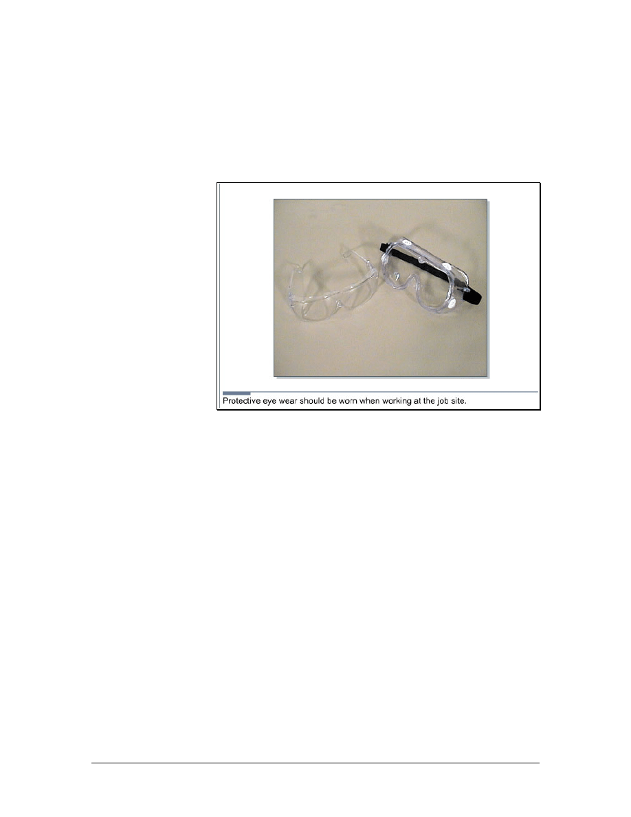
Figure 1 Eye Protection
Eyes are much easier to protect than to repair. Safety glasses should
be worn when cutting, drilling, sawing, or working in a crawl space.
Two types of safety glasses are shown in Figure 1. When materials
are cut, prepped, and discarded during cable termination processes,
small particles may become airborne. When working with fiber
optics, the glass fibers, adhesives, and solvents can come in contact
with the eyes. Glasses also protect the eyes from contaminated hands.
Small particles or chemicals on fingers may be rubbed into the eyes.
Safety glasses should also be worn when working in a crawl space or
above a dropped ceiling to protect eyes from falling objects. Many
job sites require safety glasses at all times.
Eye protection should be worn in all labs. Before starting any lab
exercise, review the safety instructions and safety equipment needed.
3.4.3 Hard hat use
Hard hats may be required at job sites, especially those involving
construction. Many employers will supply hard hats or require
installers to buy their own. Hard hats may display company colors or
logos to identify the wearer as belonging to a certain organization. If
purchasing a hard hat for personal use, do not decorate it without
41 - 125 CCNA 1: Networking Basics v3.0 – Structured Cabling Supplement
Copyright
2003, Cisco Systems, Inc.

permission from the employer. OSHA does not allow stickers on hard
hats since they could hide cracks.
Periodically check the hard hat for cracks. A cracked hat may fail to
protect a head. For hardhats to provide effective protection, they must
be adjusted properly. Adjust the internal straps and ensure that the hat
fits snugly and comfortably. Hard hats are required when working on
top of a ladder and are often required when working in new
construction environments.
42 - 125 CCNA 1: Networking Basics v3.0 – Structured Cabling Supplement
Copyright
2003, Cisco Systems, Inc.

4 Tools of the Trade
4.1 Stripping and Cutting Tools
Figure 1 Panduit UTP Cable Stripping Tool
Figure 2 Electrician Scissors and Cable Knife
43 - 125 CCNA 1: Networking Basics v3.0 – Structured Cabling Supplement
Copyright
2003, Cisco Systems, Inc.
Stripping tools are used to cut cable jackets and wire insulation. The
Panduit UTP cable-stripping tool, which is shown in Figure 1, is used
to remove the outer jacket from four-pair cables. It can also be used
for most coaxial cable. The tool features an adjustable cutting blade
to accommodate cables with different jacket thickness. The cable is
inserted into the tool. Then the tool is twisted around the cable. The
blade cuts through the outer jacket only, allowing the installer to pull
the jacket off of the cable to expose the twisted pairs.
The electrician scissors and cable knife set, shown in Figure 2, can
also be used to remove cable jackets. The knife is used for large
cables such as those that enter the building from the telco or ISP. This
knife is very sharp so gloves should be worn when working with it.
The gloves should be able to protect the hand from injury if the knife
slips.
The scissors can be used to cut individual wires, remove the outer
jacket of smaller cables, and remove the insulation on individual
wires. The scissors have two different size notches on the back of the
blade that will strip insulation on 22-gauge to 26-gauge wires.
4.2 Termination Tools
Figure 1 Panduit Multi-Pair Impact Tool
44 - 125 CCNA 1: Networking Basics v3.0 – Structured Cabling Supplement
Copyright
2003, Cisco Systems, Inc.
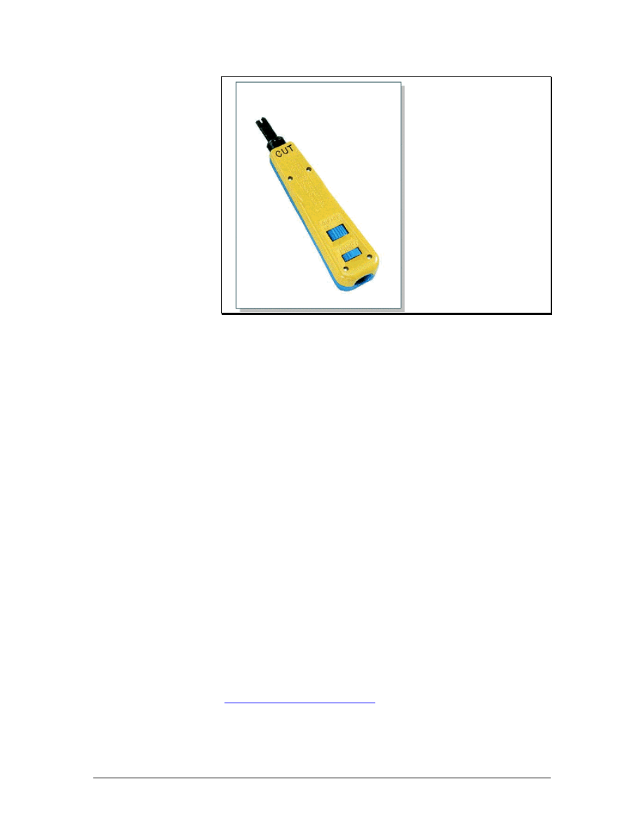
Figure 2 Panduit Impact Tool
Termination tools are designed to cut and terminate specific types of
cable. The multi-pair termination tool, which is shown in Figure 1, is
designed to terminate and cut UTP cable and seat connecting blocks.
This tool features an ergonomically designed handle, which helps
reduce fatigue when trimming wire or seating connecting blocks to
the wiring base. It also has the following features:
• Five pairs can be terminated at a time.
• Wires on both the cable side and the cross-connect side of
connecting blocks can be terminated.
• Replacement cutting blades are available.
• It can be used in the cut or non-cut position.
• The cut designation is clearly displayed for proper orientation
during termination.
• The impact mechanism is reliable.
• The ergonomically designed rubber handle has a ribbed edge,
which provides a no-slip grip.
The impact punch down tool, which is shown in Figure 2, has
interchangeable blades. This tool can terminate wires on 66 and 110
hardware. Unlike the multi-pair termination tool, this tool terminates
one wire at a time. The reversible blades have a punch and cut
function on one side and a punch only function on the other.
45 - 125 CCNA 1: Networking Basics v3.0 – Structured Cabling Supplement
Copyright
2003, Cisco Systems, Inc.
4.3 Diagnostic Tools
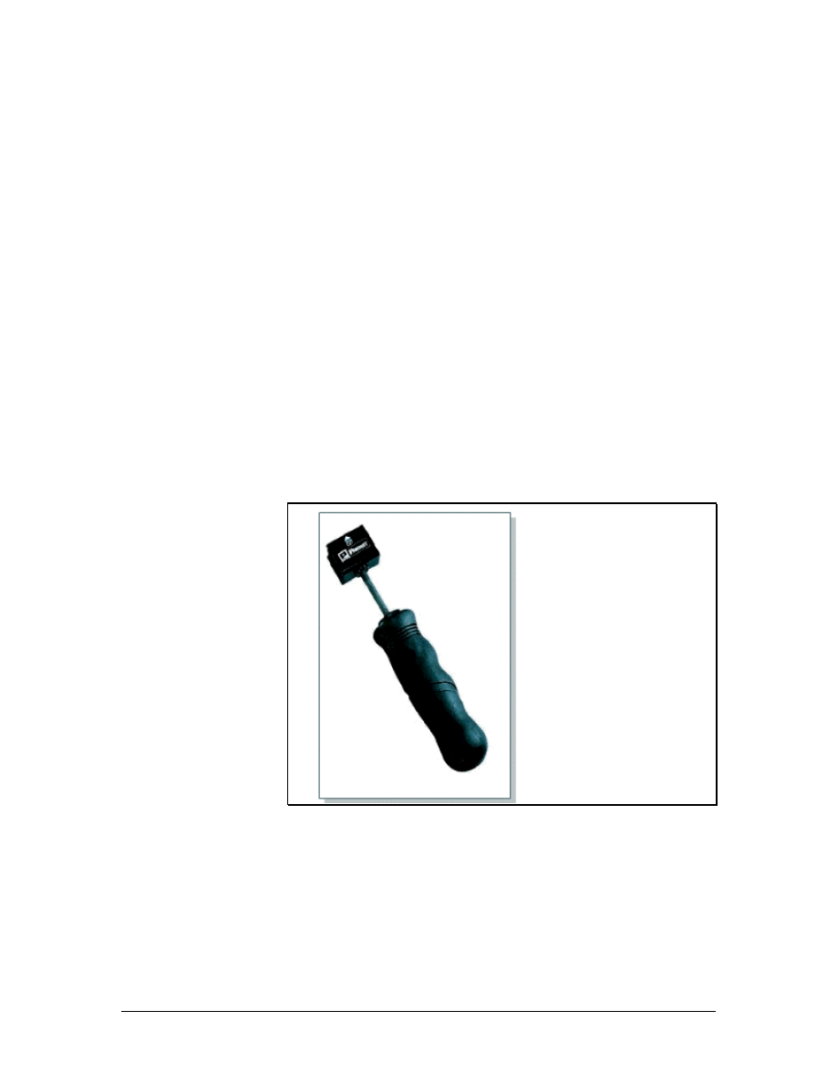
Figure 1 Modular Adapter (Banjo)
Figure 2 Stud Sensor
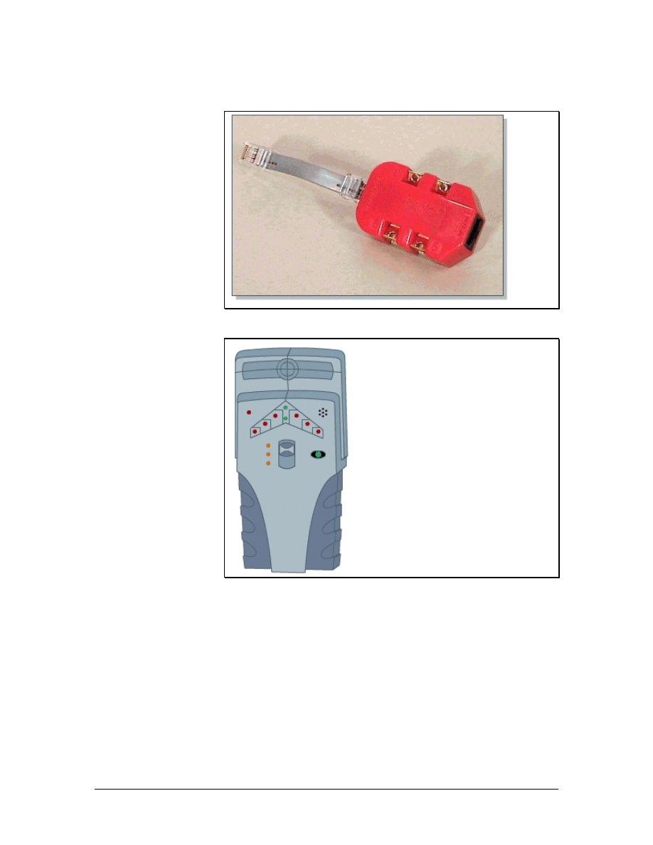
The modular adapter, or banjo, is used to provide access to individual
wires inside a telecommunications outlet or jack. This tool is shown
in Figure 1. A common line cord is plugged into the adapters and then
into the jack. Technicians can use ohmmeters or other test devices
without having to disassemble the jack. Banjos come in 3-pair and 4-
pair configurations.
Wood and metal sensors are used to locate metal pipes, wood studs or
joists, or other infrastructure behind a wall or under a floor. Sensors
should be used before drilling for any cabling project. A deep
scanning metal sensor can find metal studs, conduit, copper piping,
electrical lines, rebar, telephone lines, cable lines, nails, and other
46 - 125 CCNA 1: Networking Basics v3.0 – Structured Cabling Supplement
Copyright
2003, Cisco Systems, Inc.
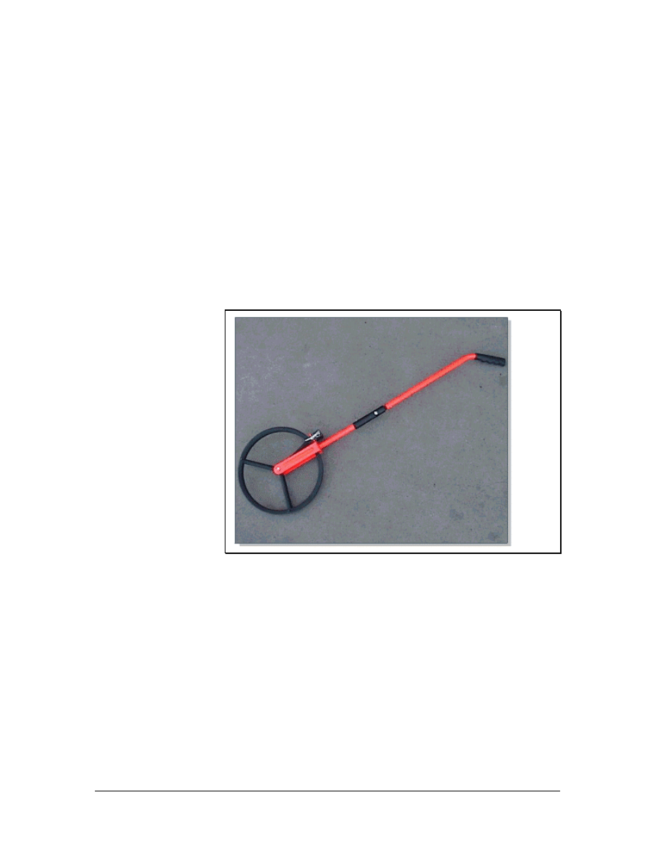
metal objects. This tool can usually scan through up to 15 cm (6
inches) of a nonmetallic surface like concrete, stucco, wood, or vinyl
siding. It identifies both the location and depth of piping or rebar with
an accuracy of plus or minus 30 cm (12 inches).
Another type of sensor is a stud sensor, which is shown in Figure 2.
This sensor locates wooden studs and joists behind walls. This tool
helps installers determine the best locations to drill or saw when
installing outlets or raceways. The stud and rebar sensor also detects
metal and can find rebar embedded in up to 100 cm (39.4 inches) of
concrete. All the modes detect AC wires to prevent installers from
drilling or nailing into a live electrical wire.
4.4 Installation Support Tools
Figure 1 Measuring Wheel
Cable installers often use measuring wheels to estimate the length of
a cable run. The wheel, which is shown in Figure 1, has a counter
mounted on the side. An installer rolls the wheel down the intended
cable path. At the end of the path, the counter will display the
distance.
Cable installers also need tools and materials for cleaning up job
sites. Brooms, dustpans, and vacuums simplify the cleanup process.
Cleanup is one of the final and most important steps in completing a
cabling project. A shop vacuum is designed for industrial jobs.
47 - 125 CCNA 1: Networking Basics v3.0 – Structured Cabling Supplement
Copyright
2003, Cisco Systems, Inc.
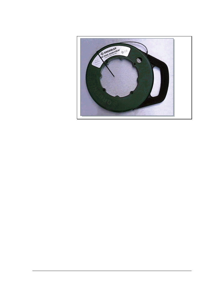
4.4.1 Fish tape
Figure 1 Fish Tape
Fish tapes are designed to simplify the retrieval of wires inside a wall.
A fish tape, which is shown in Figure 1, can be passed through walls
or conduits. First the fish tape is run to its intended destination or
some convenient partway point. Then the cable is secured to the end
of the fish tape. Pulling the fish tape, winding it onto its reel for
storage, retrieves the desired cable.
For cabling work, fiberglass fish tape is safer than steel fish tape.
Most cable installers pull a string with their cables. This provides a
convenient way to pull extra cables later on. The cable can be tied to
the pull string and pulled through the path rather than having to use
the fish tape once more.
48 - 125 CCNA 1: Networking Basics v3.0 – Structured Cabling Supplement
Copyright
2003, Cisco Systems, Inc.
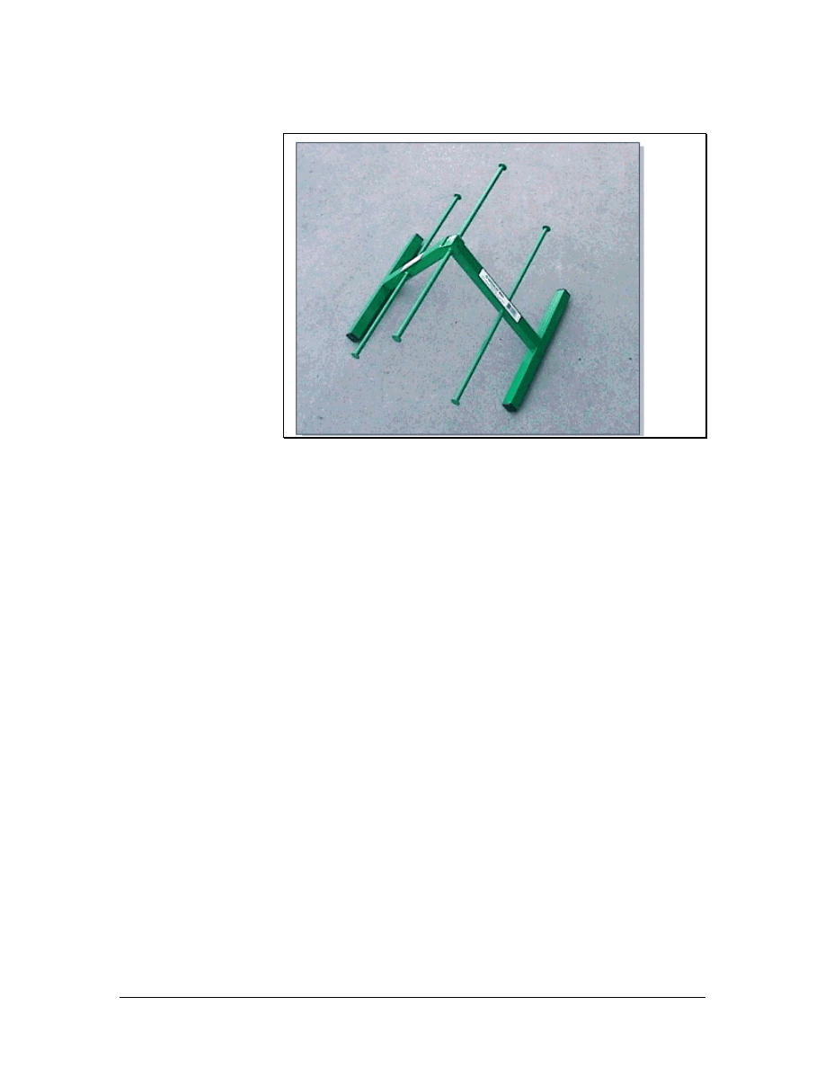
4.4.2 Cable tree
Figure 1 Cable Tree
During the rough-in phase, cable trees, jacks, and rollers are used to
support cable reels. This simplifies the process of laying cables and
helps prevent injuries. A cable tree, which is shown in Figure 1,
supports several small reels of cable. This allows the cable installer to
pull multiple runs of cable simultaneously. Since all cables terminate
at the TR, a cable tree is set up in the staging area. After cable is
pulled to a jack location, the other end is cut from the reel and pulled
into the TR.
Cable jacks and reel rollers are designed for the large reels that hold
backbone cabling. Since many large reels are too heavy to lift, cable
jacks provide enough leverage to allow two people to raise them.
Once raised, the jacks allow the reel to rotate freely and safely during
the pulling process.
Reel rollers are also used to support large cable reels. Rollers come in
sets of two. Each roller is used to support one side of the reel. Rollers
mounted on bearings allow the reel to be turned easily. When pulling
from a reel roller, one installer is generally stationed at the reel to
assist with the turning.
4.4.3 Bullwheels
Bullwheels are normally used for the first or last turn in a path. They
can also be used for an offset or turn in the center of a run.
A bullwheel is a large pulley that is used in a mechanical cable
pulling process. Bullwheels are seldom used to pull a cable by hand.
A bullwheel is generally made of aluminum, is at least 30 cm (12
inches) in diameter, and is supported on a bearing on its frame.
49 - 125 CCNA 1: Networking Basics v3.0 – Structured Cabling Supplement
Copyright
2003, Cisco Systems, Inc.
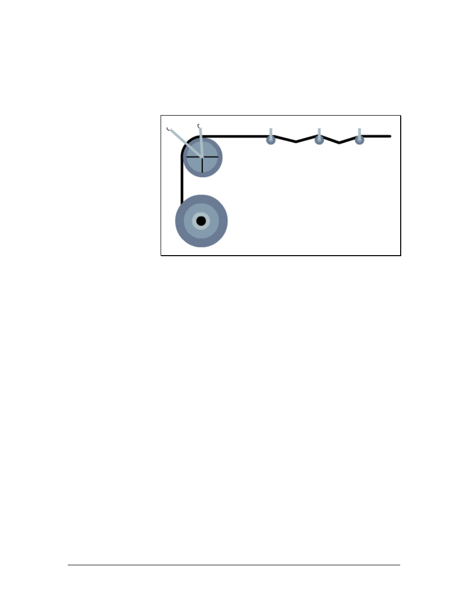
Unlike a pulley, a bullwheel often has two shackles for attachment to
fixed points. It can also be removed from its frame and put in a cable
run from the middle of the cable.
4.4.4 Pulleys
Figure 1 Cable Pull Using a Bullwheel and Pulleys
Pulleys are used on long, open cable runs to support cables and
prevent them from dragging on surfaces that could damage the cable
sheath. They are also used on surfaces that could be damaged by a
cable being pulled across it. Pulleys are used in straight cable runs to
support the weight of the cable and reduce pulling friction. Pulleys
can also assist with minor offsets in the cable run. A cable run using
pulleys is shown in Figure 1.
Pulleys are used when pulling by hand or when using a cable puller or
winch. When turns in the run exceed 45 degrees, bullwheels are used
instead.
Pulleys are used for multiple network cable runs and heavy backbone
cable runs. Lightweight pulleys can be used for network cable runs,
while heavy-duty pulleys should be used for backbone cables.
Backbone cable pulleys have a larger frame and the pulley wheel is a
larger diameter.
50 - 125 CCNA 1: Networking Basics v3.0 – Structured Cabling Supplement
Copyright
2003, Cisco Systems, Inc.
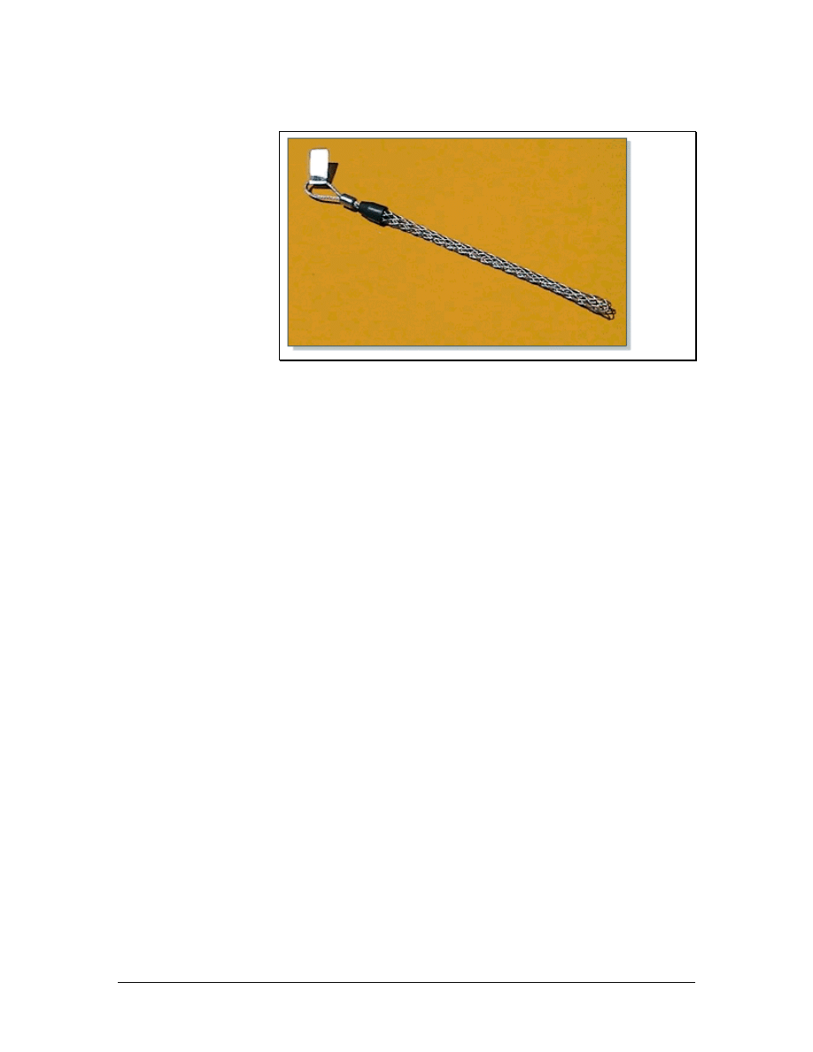
4.4.5 Wire mesh or Kellem grips
Figure 1 Wire Mesh or Kellem Grip
Wire mesh or Kellem grips allow pulling ropes to be tied to the end
of a cable. The grip is slid over the end of the cable, and the last 15
cm (6 inches) are taped tightly with a good quality vinyl electrical
tape. As tension is placed on the cable, the grip draws tighter around
the sheath of the cable. These grips are generally designed for single
cable use and should not be used with a bundle of network
distribution cables. These grips come in various sizes to
accommodate different cable sizes. A Kellem grip is shown in Figure
1.
Kellem grips are also available in a split version, if the end of the
cable is not accessible. Split versions are used to pull additional slack
in the middle of a cable run. Split grips are also used to support large
backbone cables in riser installations, when cables are pulled between
floors. To attach split Kellem grips, the grip is opened and placed
around the cable. A special rod is then threaded through the wire
mesh.
51 - 125 CCNA 1: Networking Basics v3.0 – Structured Cabling Supplement
Copyright
2003, Cisco Systems, Inc.

5 Installation Process
There are four phases that cover all aspects of a cabling project:
• Rough-In Phase – In the rough-in phase, all of the cables
are installed in the ceilings, walls, floor ducts, and risers.
• Trim Out Phase – The main tasks during the trim out phase
are cable management and the termination of wires.
• Finish Phase – The main tasks during the finish phase are
cable testing, troubleshooting, and certification.
• Customer Support Phase – In this phase, the customer
conducts a walk-through of the network and is presented
with formal test results and other documentation, like as-
built drawings. If satisfied, the customer will sign off on the
project. The cable installation company will provide ongoing
support to the customer if there are problems with the
cabling.
5.1 Rough-In Phase
During the rough-in phase the cable is pulled from a work area, or
staging area, to individual rooms or work areas. Each cable is labeled
on both ends for identification. In the work area, extra cable should
be pulled so that there is plenty to work with when terminating. If a
cable will run behind a wall, it is pulled out at the termination end so
that it is ready for termination in the next phase.
A new construction environment is usually less challenging than a
remodeling project since there are fewer obstructions. Most new
environments do not require special planning. Structures that will
support cables and terminals are generally built as needed. However,
coordination on the job site is essential. Other workers must be aware
of data cable locations to avoid damaging the newly installed cables.
The cable installation operation begins in the staging area. This area
is generally located near the TR since one end of every cable will be
terminated in the TR. Proper set up of equipment will save time
during the cable pulling process. Different types of cable runs will
require different setups. Network distribution cabling normally
requires multiple small cable reels. Backbone cabling generally
requires a single large reel of cable.
Lab 4: Identification of Cables
52 - 125 CCNA 1: Networking Basics v3.0 – Structured Cabling Supplement
Copyright
2003, Cisco Systems, Inc.
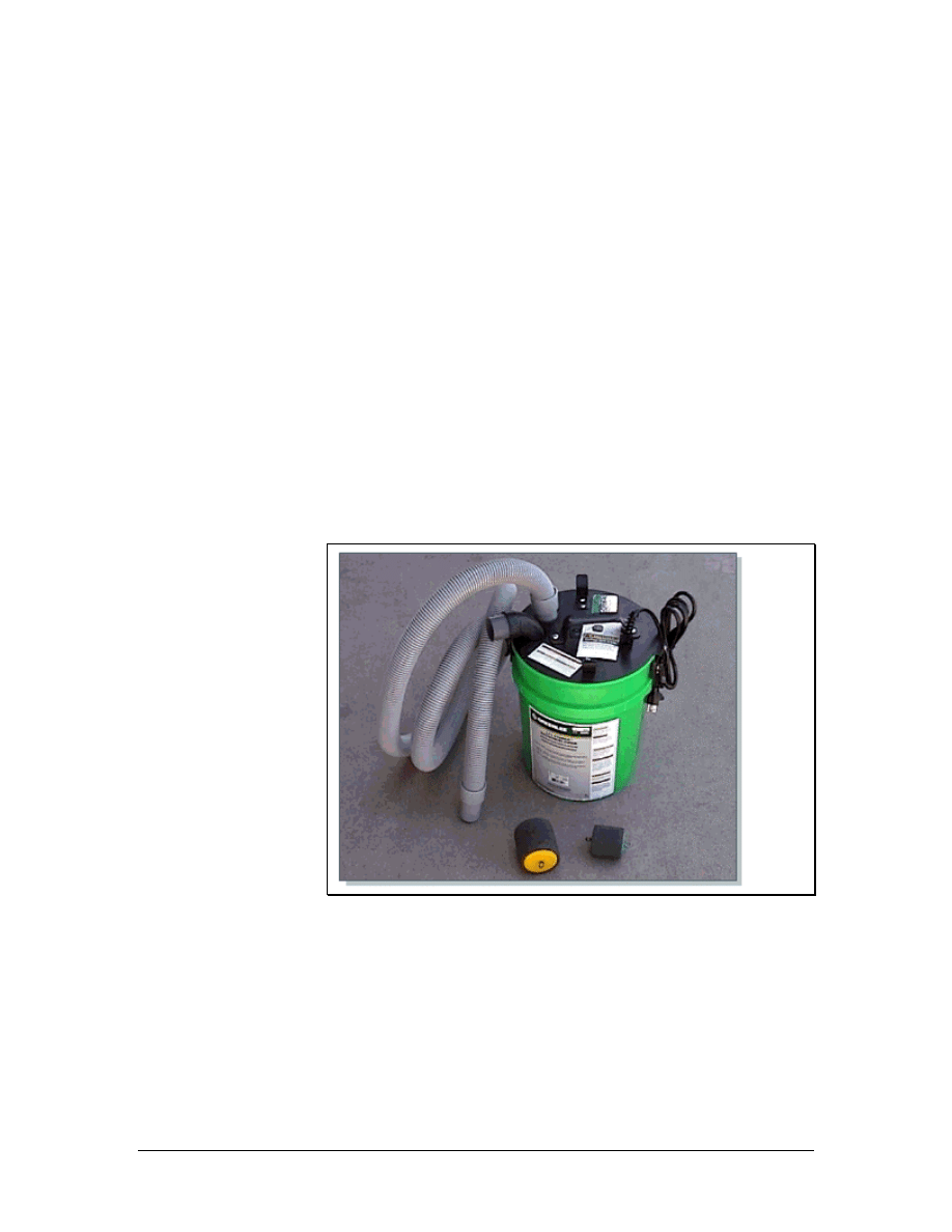
5.1.1 Horizontal cable installation
Horizontal cable is cable that travels between the HC and the work
area outlet. The cable can travel either horizontally or vertically.
During the installation of horizontal cable, it is important to follow
these guidelines:
• Cables should always run parallel to walls.
• Cables should never be placed diagonally across a ceiling.
• The cabling path should be the most direct path with the
fewest number of turns.
• Cables should not be placed directly on top of ceiling tiles.
After the backbone cabling has been installed, the horizontal network
distribution cable must be installed. Network distribution cable
provides network connectivity from the backbone cabling. Network
distribution cable usually travels from workstations back to the TR,
where it is interconnected to the backbone cabling.
5.1.2 Horizontal cable installation in conduits
Figure 1 Conduit Blowing System
The installation of horizontal cables in conduits requires similar
setups and procedures as the installation of cables in an open ceiling.
Pulleys are not necessary since the cables are supported within the
conduits. Although the initial staging is the same, there are some
special techniques and considerations for cable pulls in conduits.
The conduit must be large enough to handle all the cables that are
being pulled. Conduits should never be filled to over 40 percent of
their capacity. There are charts that list the maximum cable fill for
53 - 125 CCNA 1: Networking Basics v3.0 – Structured Cabling Supplement
Copyright
2003, Cisco Systems, Inc.
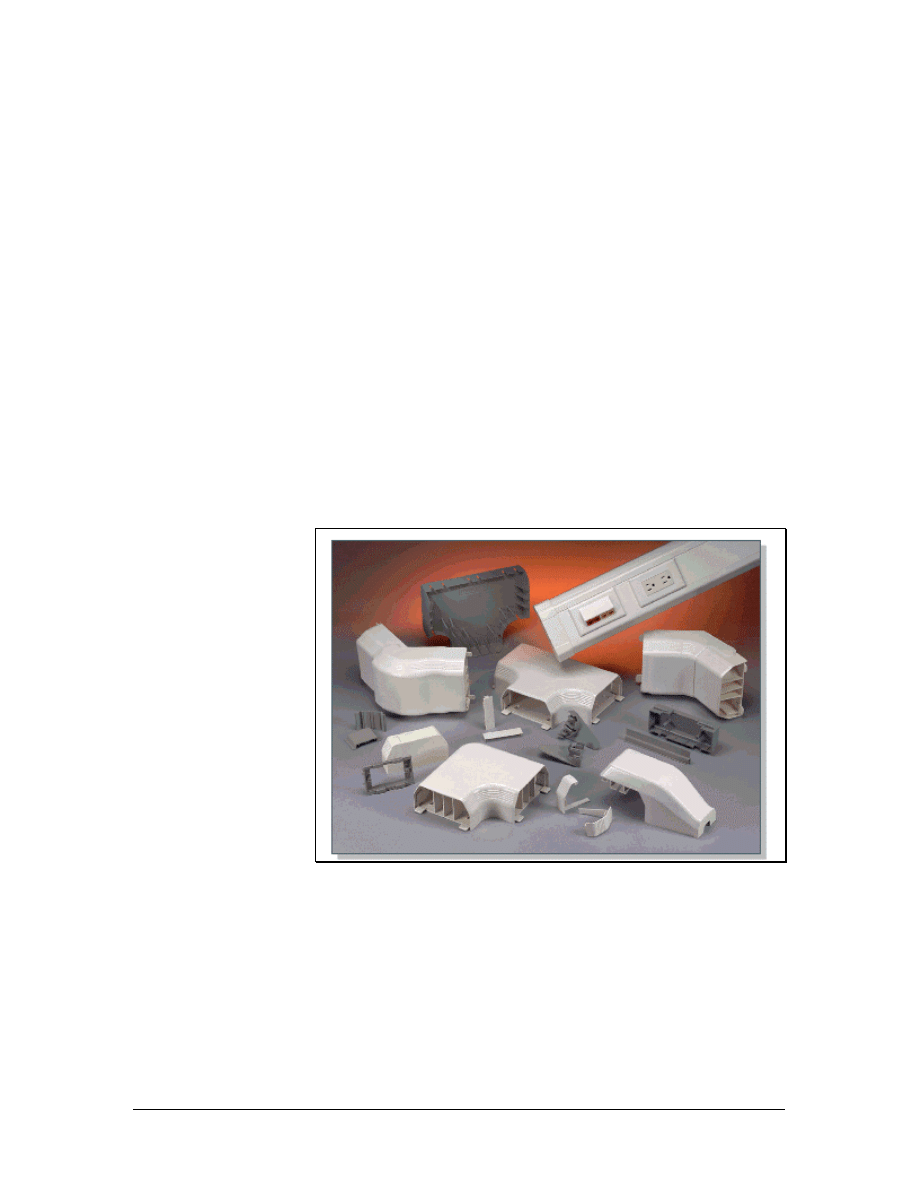
specific conduits. The length of the run and the number of 90-degree
bends in the conduit must also be considered. Conduit runs should not
exceed 30 m (98 feet) without a pull box and should not have more
than two 90-degree bends. Large cable pulls require long-radius
conduits for the bends. The standard radius for a 10-cm (4-inch)
conduit is 60 cm (24 inches). A conduit with a radius of at least 90
cm (35 inches) should be used in larger pulls.
A specialized vacuum cleaner attachment, which can help with
conduit runs, is shown in Figure 1. A special foam rubber missile,
sometimes referred to as a mouse, can be inserted into the conduit
with a light pull string tied to the missile. When the missile is slightly
lubricated with liquid detergent, a high-powered vacuum cleaner can
draw the missile and the pull string through an entire conduit run.
Special attachments for the vacuum can also be used to blow the
missile through the conduit. For difficult runs, one vacuum can be
used to blow on one end while another vacuum pulls at the other end.
When the string reaches the other end of the conduit, it is used to pull
the cables through the conduit.
5.1.3 Raceways
Figure 1 Raceways
A raceway is a channel that contains cables in an installation.
Raceways include common electrical conduits, specialized cable trays
or ladder racks, in-floor duct systems, and plastic or metal surface
mounted raceways.
Surface mounted raceways, like the ones shown in Figure 1, are used
when there is no hidden path for the cable. Plastic surface mounted
raceway comes in various sizes to accommodate any number of
54 - 125 CCNA 1: Networking Basics v3.0 – Structured Cabling Supplement
Copyright
2003, Cisco Systems, Inc.
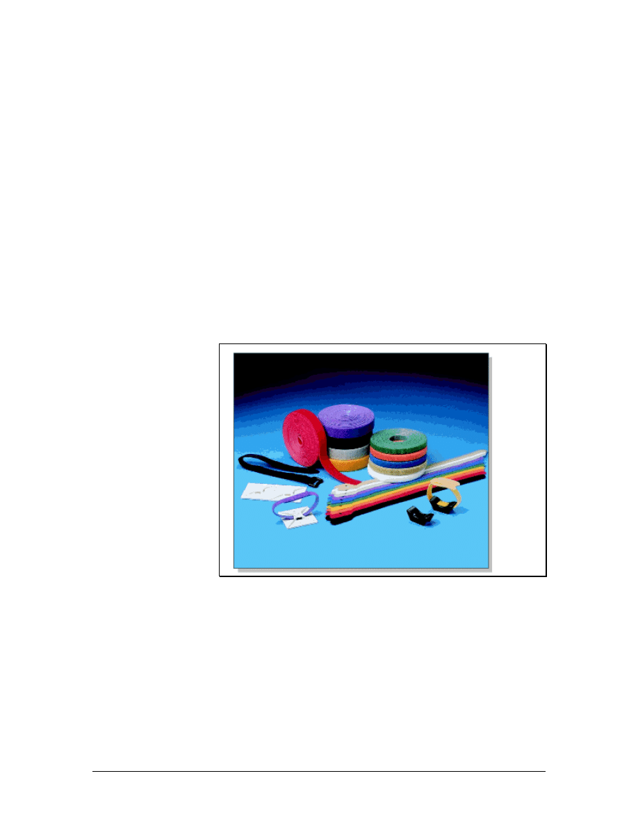
cables. These are easier to install than metallic conduits and are
considered to be much more attractive.
5.1.4 Pulling cable to the jacks
In the work area, cables must be pulled to a jack or outlet location. If
conduits are used to run behind the walls from the ceiling to the outlet
boxes, a fish tape can be inserted into the outlet box at one end of the
conduit and pushed up the conduit into the open ceiling. The cable
can be attached directly to the fish tape and then pulled down from
the ceiling and out through the outlet box.
Some walls, such as concrete or brick walls cannot have cable runs
behind them. Therefore, surface mounted raceways are used. Before
installing cables, the surface mounted raceways should be secured to
the wall according to the recommendations of the manufacturer. After
the cable has been pulled to the outlets, the cable installer will return
to the TR to pull the cable at that end.
5.1.5 Fastening cable
Figure 1 Panduit Hook and Loop Ties
The final step in the rough-in process is to permanently fasten the
cables. Many types of fasteners are available, such as J-hooks and
hook and loop ties, as shown in Figure 1. Network cables should
never be tied to electrical cables. This may appear to be the most
practical approach, especially for individual cables or small bundles.
However, it violates the electrical code. Cables should never be tied
to water or sprinkler pipes.
High performance networks cables have a minimum bend radius that
cannot exceed four times the diameter of the cable. Therefore, use
fasteners that support the minimum bend radius. Fastener spacing
55 - 125 CCNA 1: Networking Basics v3.0 – Structured Cabling Supplement
Copyright
2003, Cisco Systems, Inc.

may be defined in the job specifications. If no spacing is specified,
fasteners should be placed at intervals that do not exceed 1.5 m (5
feet). If a cable tray or basket is installed in the ceiling, permanent
fasteners are not necessary.
5.1.6 Horizontal cabling precautions
It is important to avoid damaging the cable or its sheath when pulling
it. Too much tension or making corners so tight that they exceed the
bend radius can decrease the ability of a cable to carry data. Installers
stationed along the route of the pull should watch for snags and
possible trouble spots before damage occurs.
Several precautions should be taken when pulling horizontal cabling:
• As the cable enters the conduit, it can become caught or get
scuffed on the end of the conduit. Use a plastic conduit guard
or shoe to avoid this type of sheath damage.
• Extremely hard pulls around a 90-degree turn can cause
cables to flatten, even when using bullwheels and pulleys. If
pulling tension is too great, shorten the length of the pull and
do it in stages. Do not exceed a pull tension of 3.5 kg/m (25
feet/lb) pull tension for twisted pair cable, or 6.0 kg/m (50
feet/lb) for fiber.
• When pulling with a cable puller or winch, it is important to
perform the pull in a single smooth action. After beginning
the pull, try to continue the pull until completion. Stopping
and starting can cause additional stress to the cable.
56 - 125 CCNA 1: Networking Basics v3.0 – Structured Cabling Supplement
Copyright
2003, Cisco Systems, Inc.

5.1.7 Mounting jacks in drywall
SAFETY RULES
When working in walls, ceilings, or attics, the first thing to do is turn
off power to all circuits that might pass through those work areas. If it
is not clear whether wires pass through the section of the building
being worked in, a good rule to follow is to shut off all power.
WARNING: Never, ever, touch power cables. Even if all power has
been cut to the area being worked in, there is no way to know if they
are "live".
Before beginning work, learn the locations of all fire extinguishers in
the area.
Wear appropriate clothing. Long pants and sleeves help protect arms
and legs. Excessively loose or baggy clothing should not be worn as it
could catch on something.
If working in a dropped ceiling area, survey the area. Do this by
lifting a few of the ceiling tiles and looking around. This will help to
locate electrical conduit, air ducts, mechanical equipment, and
anything that might possibly cause problems later.
Protect the eyes with safety glasses when cutting or sawing. It is also
a good idea to wear safety glasses when working in a crawl space or
above a dropped ceiling. If something falls from above, or in the dark,
the eyes will be protected.
Consult the maintenance engineer of the building to find out if there
is asbestos, lead, or PCBs where the work is being done. If so, follow
all government regulations in dealing with that material.
Keep the work area orderly and neat. Do not leave tools lying in
places where someone might trip over them. Use caution with tools
that have long extension cords. Like tools, they are easy to trip over.
To mount an RJ-45 jack in drywall, follow these steps:
1. Select a position for the jack that will be 30-45 cm (10–15 inches)
above the floor. Drill a small hole in the selected location. Check
for any obstructions behind the hole by bending a piece of wire,
inserting it into the hole, and rotating it in a circle. If the wire hits
something, there is an obstruction there and a new location farther
away from the first hole must be selected. Then the procedure
must be done again until an unobstructed location can be found.
57 - 125 CCNA 1: Networking Basics v3.0 – Structured Cabling Supplement
Copyright
2003, Cisco Systems, Inc.

CAUTION
When working in walls, ceilings, or attics, it is extremely
important to remember to turn off the power to all circuits that
go to, or pass through, the work area. If it is unclear whether
there are wires that pass through the section of the building, a
good rule to follow is to shut off all power.
2. Determine the size of the opening needed for the box that will hold
the jack. This can be done by tracing an outline of the template
that was included with the box or bracket.
3. Before cutting into the wall, use a carpenter's level to make sure
the opening will be straight. Use a utility knife to cut the opening.
Push the knife through the drywall, inside the template outline,
until there is an opening large enough to accommodate the blade
of either a keyhole saw or a drywall saw.
4. Insert the saw into the hole, and cut along the edge of the penciled
outline. Continue cutting carefully along the line until the piece of
drywall can be pulled out. Make sure the box or bracket will fit the
opening.
5. If using a box to flush-mount the jack, do not secure the box until
after bringing the cable to the opening.
5.1.8 Mounting jacks in plaster
It is more difficult to cut into a plaster wall than it is to cut into
drywall. To achieve the best results, follow these steps:
1. Determine the appropriate location for the jack.
2. Use a hammer and chisel to remove the plaster from the wall so
that the lath behind the plaster is exposed.
3. Use a utility knife to carefully trim plaster away from the lath.
4. Place the template against the lathwork so that it overlaps three
strips of lath, equally, at the top and bottom of the opening. Trace
an outline around the template. Use an electric saw to cut away the
full lath strip that is exposed in the center of the opening.
5. Make several small cuts on the full strip, first on one side, and
then on the other. Continue to make these small cuts until the
center lath has been completely cut through.
CAUTION
Be careful when doing this step. If attempting to cut all the way
through one side before cutting into the other side, the saw will
cause the lath to vibrate when making the second cut. This can
cause the plaster around the opening to crack and separate
from the lath.
58 - 125 CCNA 1: Networking Basics v3.0 – Structured Cabling Supplement
Copyright
2003, Cisco Systems, Inc.

6. Finish preparing the opening by removing the required portions of
the lath strips at the top and bottom. Do this by cutting vertically
along the sides of the hole. Make several small cuts on first on one
side and then on the other as before. Continue until the laths are
notched even with the top and bottom of the hole. Now cut a curve
in the bottom piece of lath from the top right corner to the bottom
left corner. Bottom out the curve so that it is flat just before it gets
to the corner. Remove the lath that should fall free when the cut
reaches the corner. Turn the saw around and cut flush along the
bottom of the hole until the opposite corner is reached. The
remaining lath should fall free. Repeat the process for the top
piece of lath.
5.1.9 Mounting jacks in wood
To prepare the wood for flush mounting a jack, follow these steps:
1. Select the position where the box will be placed. Remember, if the
RJ-45 jack is placed on a wooden baseboard, avoid cutting the box
opening into the bottom 5 cm (2 inches) of the baseboard.
2. Use the box as a template, and trace around the outside. Drill a
starter hole in each corner of the outline.
3. Insert a keyhole saw, or jigsaw, into one of the holes and saw
along the outline until reaching the next hole. Turn the saw and
continue cutting until the piece of wood can be removed.
5.1.10 Flush mounting a jack in a wall
After preparing an opening in which to position the jack, place it in
the wall. If using a box to mount the jack, hold the cable, and feed it
through one of the slots into the box. Then push the box into the wall
opening. Use the screws to secure the box to the wall's surface. As the
screws are tightened, the box will be pulled tighter to the wall.
If mounting the jack in a flat low-voltage mounting bracket,
sometimes called a “wallboard adapter” or “old work box” box,
position it now. Place the bracket against the wall opening, the
smooth side facing outward. Push the top and bottom flanges toward
the back so that the bracket grips the wall. Then, push one side up and
the other down, to securely mount the bracket.
59 - 125 CCNA 1: Networking Basics v3.0 – Structured Cabling Supplement
Copyright
2003, Cisco Systems, Inc.
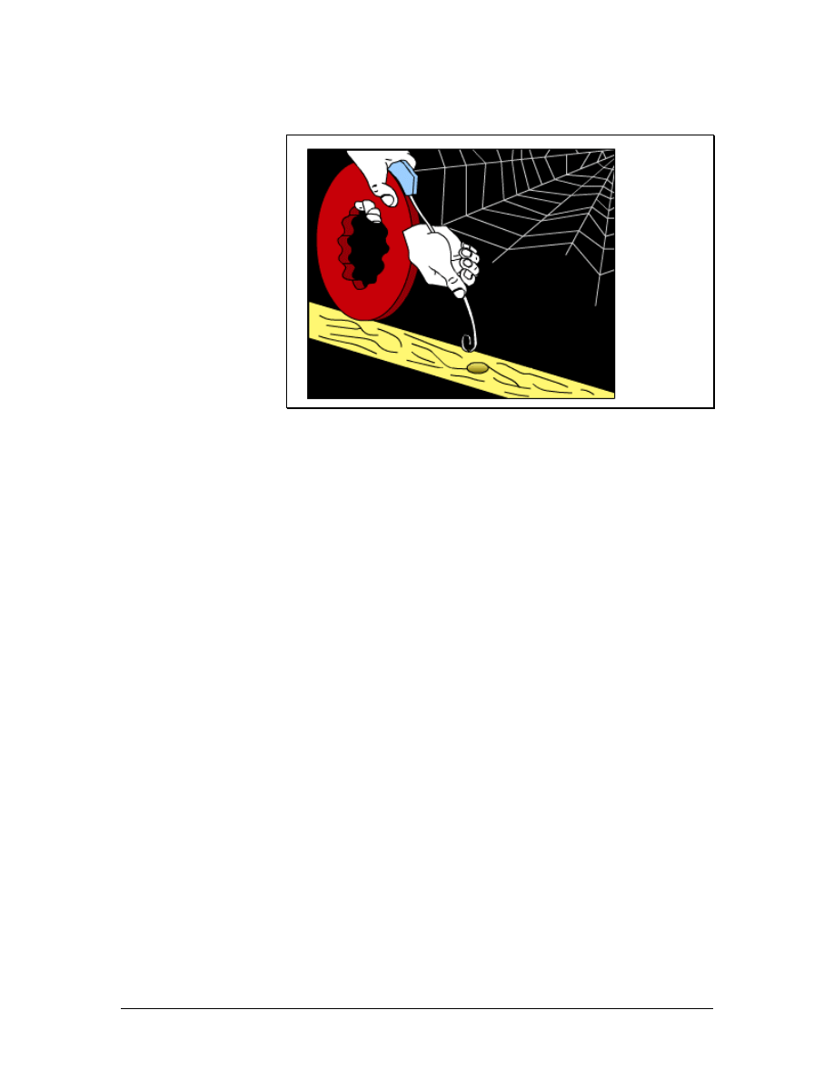
5.1.11 Pulling cable to the jacks
Figure 1 Pulling cable to the jacks with a fish tape
At the work area end of the cables, the cable must be pulled to the
jack or outlet location. If conduits are used to run behind the walls
from the ceiling to the outlet boxes, a fish tape can be inserted into
the outlet box at the end of the conduit and pushed up the conduit
until it comes out into the open ceiling. The cable can be attached
directly to the fish tape and then pulled down from the ceiling and out
through the outlet box as shown in Figure 1.
If there are no conduits in the walls, the cable can be pulled behind
the wall. First, a hole is cut into the drywall at the location of the jack.
Care must be taken to avoid making the hole too large. Another hole
is drilled into the top plate of the wall. This hole should be 1–2 cm
(0.4–0.8 inches) in diameter. A fish tape is pushed down through the
top hole, and the installer must try to find it at the lower hole. Some
installers use a weight and a string instead, which is dropped down
from the top hole and tied off so that it cannot accidentally drop down
through the hole. At the bottom hole, or outlet, the installer can use a
hook or a coat hanger to try to find the string.
Once the end of the fish tape is captured at the outlet location, a pull
string is tied to it. The fish tape is then pulled back up to the original
location where the cables are tied to the pull string. Finally, the pull
string is pulled down to the outlet location with the cables attached.
Some walls, like concrete or brick walls, will obviously not have the
cables run behind them. Surface mounted raceways are used for these
types of walls instead. Before cables are installed, the surface
mounted raceways should be secured to the wall following the
manufacturer's recommendations. After cable has been pulled through
to the outlets, the cable installers return to the telecommunications
room to finish pulling the cable at that end.
60 - 125 CCNA 1: Networking Basics v3.0 – Structured Cabling Supplement
Copyright
2003, Cisco Systems, Inc.
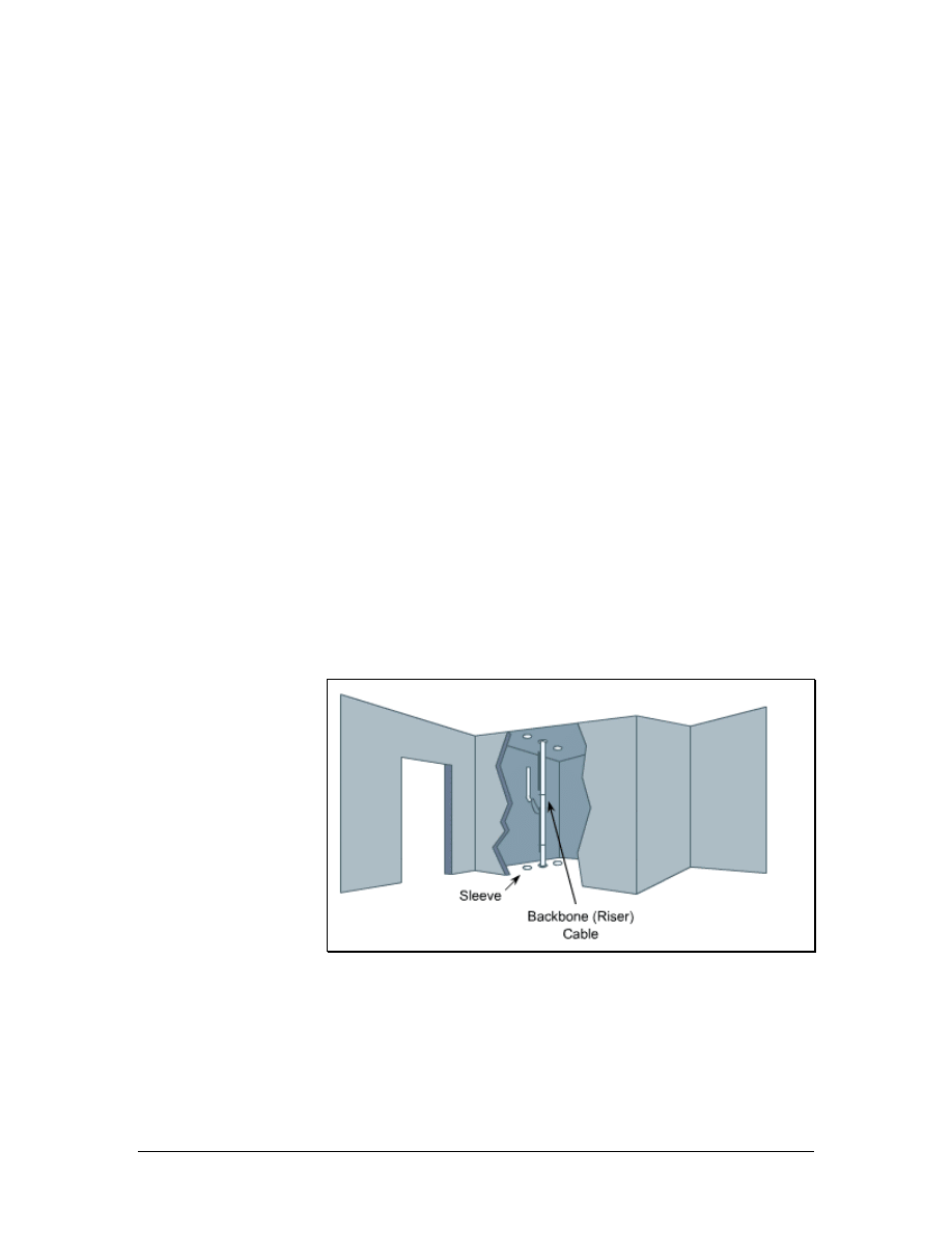
5.1.12 Fishing cable from below a wall
When running horizontal cabling in a building that has a basement,
fish cable from there to the work areas on the first floor. Do this by
following these steps:
1. Drill a 3.2 mm (1/8-inch) hole, at an angle, through the floor, next
to a baseboard.
2. Push a coat hanger or stiff piece of wire into the hole to indicate
the spot when in the basement.
3. Go to the basement and locate the wire.
4. Use a tape measure to mark a spot under the areas of the wall. This
mark should be 57 mm (2 inches) from the hole.
5. Drill a new hole in this spot. This hole should be 19 mm (0.7
inches) in diameter. Unlike the first hole that was drilled at an
angle, drill this hole straight up through the subfloor and wall
plate.
6. Push the cable up through this second hole, to the wall opening
where the work area outlet is to be located.
7. Be sure to allow enough excess cable so that it can reach the floor
and extend another 60–90 cm (2–3 feet).
5.2 Vertical Cable Installation
Figure 1 A Typical Riser
Vertical cable installation can include network distribution cables and
backbone cables. Although backbone cables may be pulled
horizontally, they are considered part of the vertical distribution
system. Network distribution cables are part of the horizontal
distribution system.
61 - 125 CCNA 1: Networking Basics v3.0 – Structured Cabling Supplement
Copyright
2003, Cisco Systems, Inc.
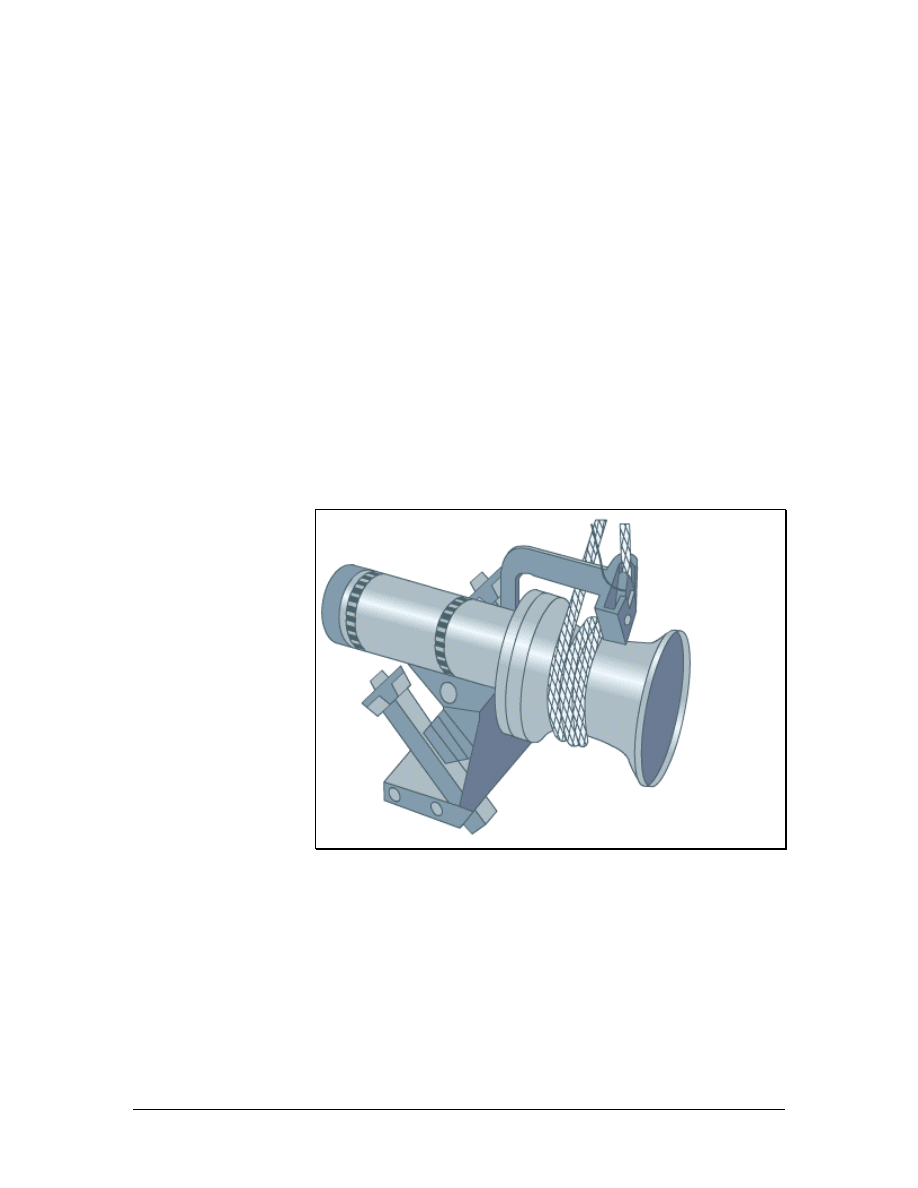
Most vertical installations are installed in conduits, in conduit sleeves
through the floors, or in slots cut through the floor. A rectangular
opening in the floor is referred to as a slot or a pipe chase. Risers are
a series of holes in the floor, typically 10 cm (4 inches) in diameter,
possibly with conduit sleeves installed. A typical riser is shown in
Figure 1. The conduit sleeves may protrude up to 10 cm (4 inches)
above and below the floor. Not all risers are stacked directly above
one another. Therefore, riser alignment should be checked before the
rough-in phase.
Vertical cable installation takes place either from an upper floor to a
lower floor or from a lower floor to an upper floor. It is usually easier
to pull cables from an upper floor to a lower floor since gravity assists
in the effort Since it is not always possible to bring large reels of
cable to upper floors, there are times when vertical cables must be
pulled from a lower floor. When pulling upwards, mechanical aids
such as winches or cable pullers are generally not needed, but reel
brakes are required to prevent a cable free fall.
5.2.1 Cable winches
Figure 1 Cable Winch
62 - 125 CCNA 1: Networking Basics v3.0 – Structured Cabling Supplement
Copyright
2003, Cisco Systems, Inc.
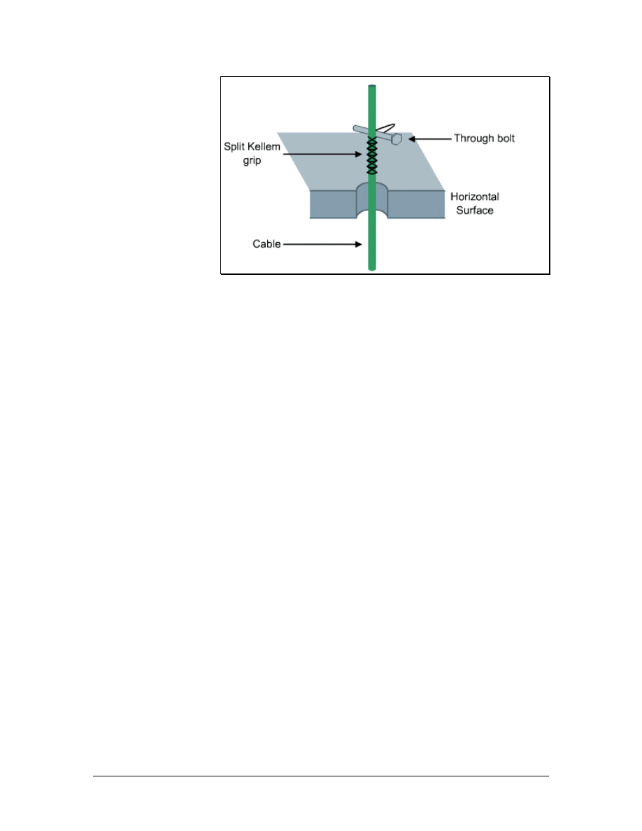
Figure 2 Split Kellem Grip Secured with a Through Bolt
Cables in vertical pulls must be lowered carefully so that the cable
does not spin off of the reel too quickly. A reel brake can help
provide added tension.
A cable winch, which is shown in Figure 1, is often used for lifting
cables. Since the equipment used for pulling cable can harm cable
installers or onlookers, only members of the cable installation crew
should be in the area. Pulling large cables with a cable winch creates
a great deal of tension on the pulling rope. If this rope were to snap,
someone in the area could be injured. Therefore, it is best to stand
away from a pull rope that is under tension.
Cables can be ordered from the factory with a pulling eye installed.
This is particularly useful for large, heavy pulls. If this is not possible,
a Kellem grip can be used. After the pull begins, it should be slow
and steady. The pull should not be interrupted unless absolutely
necessary. After the cable is pulled into place, the pull rope and
winch will hold it until it is permanently fastened between floors
using strut systems, friction clamps, or Kellem grips secured with
bolts, as shown in Figure 2.
5.2.2 Fastening vertical cables
One method for fastening vertical cables is to use a split wire mesh
grip, or a Kellem Grip, and a large bolt that is 25 to 30 cm (10 to 12
inches) long. It is important to use an appropriate grip size for the
bundle of cables. The winch or the reel brake will support the cable,
while a split wire mesh grip is installed at each floor. The bolt is
installed through the loops in the grip. The cable is then gently
lowered until it is supported by the grips. This is a permanent
installation.
63 - 125 CCNA 1: Networking Basics v3.0 – Structured Cabling Supplement
Copyright
2003, Cisco Systems, Inc.

5.2.3 Cable installation tips
The following guidelines should be used for pulling cable:
• The staging area should be close to the first 90-degree bend.
It is easier to pull cable around a bend when it first comes out
of the box or off of the reel than it is near the end of the pull.
The installer will be pulling the weight of all the cable pulled
up to that point.
• Pulling lubricant should be used for long or difficult pulls to
prevent damage to cables.
• The reel should be adjusted so that cable comes off of the top
of the reel rather than from beneath it.
• If a fish tape becomes stuck in a conduit bend, rotate it a few
turns while pushing.
• An additional piece of pull string should be pulled with the
cable. This can be used as a pull string if additional cables are
needed later. An additional pull string will eliminate the need
to use another fish tape through this space.
• If cable must be coiled on the floor for a secondary pull, coil
the cable in a figure 8 configuration to eliminate tangles
when uncoiling. Use two safety cones or buckets as guides
for coiling the cable.
• Supporting cables vertically through multiple floors can be a
challenge. Run a steel strand or messenger between the
floors, and anchor it at both ends. Vertical cable runs can be
secured to this steel strand for vertical support.
5.3 Fire-Stops
The choice of cabling materials and how they are installed can greatly
affect how a fire moves through a building, the type of smoke and
gasses emitted, and the speed at which the smoke and flames spread.
Using plenum rated cables where required, minimizing penetrations
through firewalls, and using proper fire-stopping when penetration is
unavoidable can reduce and slow the spread of smoke and flames. It
is usually smoke that is lethal, not flames.
5.3.1 Firewall
A firewall is constructed out of special materials and techniques that
will resist the movement of smoke and gasses from one area to
another. Fire-rated walls also limit the spread of flames from the area
where a fire originates to surrounding areas. This can protect building
occupants and fire fighters from exposure to toxic smoke. Firewalls
can also give the occupants extra time to evacuate the building.
64 - 125 CCNA 1: Networking Basics v3.0 – Structured Cabling Supplement
Copyright
2003, Cisco Systems, Inc.
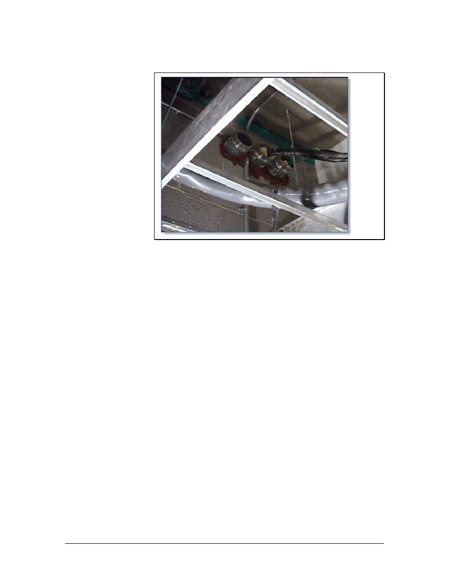
5.3.2 Firewall penetrations
Figure 1 Typical Firewall Penetration
Several types of materials are used to construct firewalls. The most
common materials are drywall and sheetrock. When applied floor to
ceiling, each layer of this material can resist the spread of flame for
approximately one-half hour. Two layers will provide protection for
twice as long. Other common firewall materials include concrete
blocks and poured concrete.
When cable must be pulled through a firewall, a hole must be drilled
through the firewall. This is called a penetration and is shown in
Figure 1. Penetrations can go all the way through the firewall. If the
penetration only goes through one side of a firewall, it is called a
membrane penetration.
After the hole is drilled, the penetration is usually sleeved by
inserting a small section of conduit in the hole. The conduit must be
large enough to hold the cables, with room for additional cables in the
future. This conduit must protrude 30 cm (12 inches) on both sides of
the wall. Cables are then pulled through the conduit. After the cables
have been pulled through the conduit, the conduit must be sealed with
an approved fire-stop material. This prevents fire from spreading
from one section of a building through a hole in the firewall.
When cables are installed in an existing firewall penetration, the fire-
stop material must be removed to clear space for the new cables.
After the new cables have been pulled, the hole and conduits should
be sealed with new fire-stop material.
65 - 125 CCNA 1: Networking Basics v3.0 – Structured Cabling Supplement
Copyright
2003, Cisco Systems, Inc.
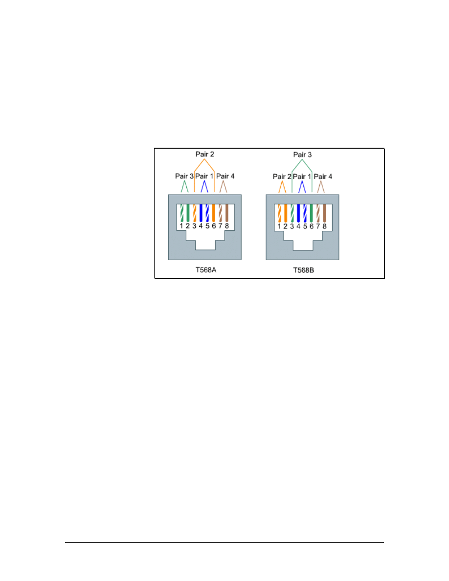
5.4 Terminating Copper Media
Communications cables are color-coded to identify individual pairs.
The color-coding is the same for all telecommunications cables in
North America. The use of color codes ensures uniformity in
identifying individual cable pairs. Each colored cable pair is
associated with a specific number.
5.4.1 Four-pair color code
Figure 1 TIA/EIA-568-A and TIA/EIA-568-B Wiring Schemes
For most voice and data cabling, UTP cables are used. These cables
have four pairs of twisted wires in each cable. The four-pair color
code is as follows:
■
Pair 1 - White/Blue
■
Pair 2 - White/Orange
■
Pair 3 - White/Green
■
Pair 4 - White/Brown
Pair 1 is always positioned on pins 4 and 5 in an eight-pin jack or
plug. Pair 4 always appears on pins 7 and 8 on an eight-pin jack or
plug. The other pairs have different appearances depending on the
standard used for the wiring plan. The different wiring schemes are
shown in Figure 1.
Either T568A or T568B should always be used for this wiring
scheme. A new wiring scheme should never be created since each
wire has a specific purpose. If the wiring is not correct, the devices on
both ends will not be able to communicate or they will experience
severely degraded performance.
If the installation is in a new building, whether to use T568A or
T568B is likely to be dictated by contract. If the choice is left to the
installers, use whatever scheme is most popular in the area. If there is
66 - 125 CCNA 1: Networking Basics v3.0 – Structured Cabling Supplement
Copyright
2003, Cisco Systems, Inc.
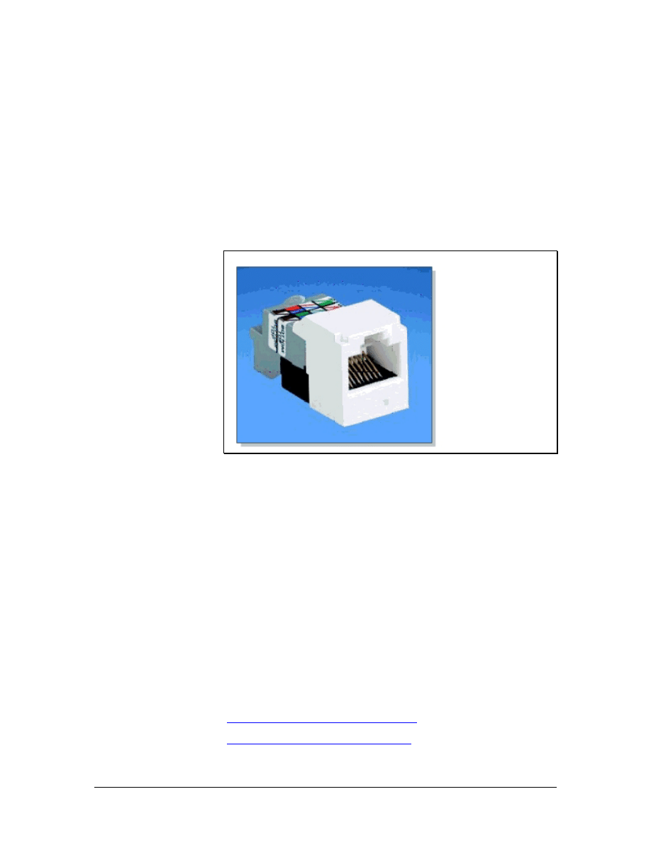
existing wiring in the building that is either T568A or T568B, follow
the existing scheme. Remember that every installer on the team must
use the same wiring scheme.
Occasionally there is some confusion over pair numbers and pin
numbers. A pin is a specific location on a plug or a jack. The colored
pairs are always the same. For example, pair 2 is always the
white/orange pair. On an RJ-45 jack, however, pair 2 may connect to
pins 3 and 6, or to pins 1 and 2, depending on whether T568A or
T568B is used.
5.4.2 RJ-45 plugs and jacks
Figure 1 RJ-45 Jack
RJ-45 jacks are eight-conductor jacks that are designed to accept
either RJ-45 plugs or RJ-11 plugs. An RJ-45 jack is shown in Figure
1. Jacks should be wired to the T568A or T568B standard.
RJ-45 plugs have eight pins that will accommodate up to four pairs of
wires. As with RJ-11 plugs and jacks, pair 1 is always terminated on
the center pins, which are pins 4 and 5. Pair 4, or the white/brown
pair, is always terminated on pins 7 and 8. Pairs 2 and 3 may differ
depending on the wiring plan. If using T568B, pair 2, or the
white/orange pair, terminates on pins 1 and 2. Pair 3, or the
white/green pair, terminates on pins 3 and 6. If using T568A, pairs 2
and 3 are reversed. Therefore, pair 2 terminates on pins 3 and 6, while
pair 3 terminates on pins 1 and 2.
An RJ-45 jack terminates one end of the horizontal cable. The other
end of the cable is typically terminated on a patch panel with a 110-
style connector or a 110-style connecting block.
Lab 5: Category 5e Jack Termination
Lab 6: Category 6 Jack Termination
67 - 125 CCNA 1: Networking Basics v3.0 – Structured Cabling Supplement
Copyright
2003, Cisco Systems, Inc.
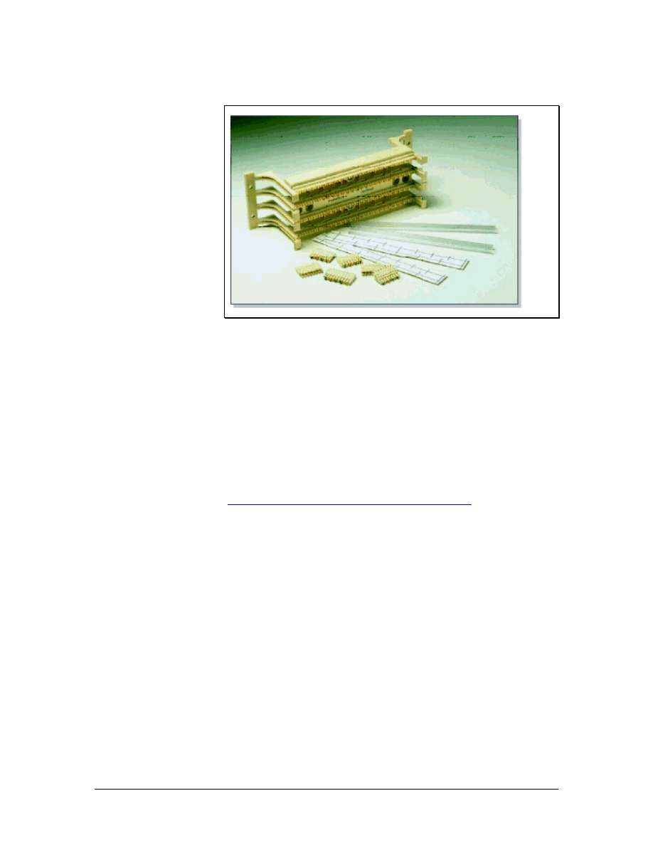
5.4.3 110-block
Figure 1 A 110-Block
110-blocks are high-density termination blocks that are used for
either voice or data applications. 110-blocks come in many
configurations, including the one shown in Figure 1. These blocks are
designed to be stacked in different combinations to accommodate
different size requirements. The 110 system includes wire
management devices that also act as spacers between the blocks.
Some 110-blocks have a special multipunch tool that can punch down
up to five pairs of wire at a time. This tool should not be used on
patch panels that contain printed circuit boards. The impact could
damage the internal wiring.
Lab 7: Terminating Category 5e to a 110-Block
68 - 125 CCNA 1: Networking Basics v3.0 – Structured Cabling Supplement
Copyright
2003, Cisco Systems, Inc.
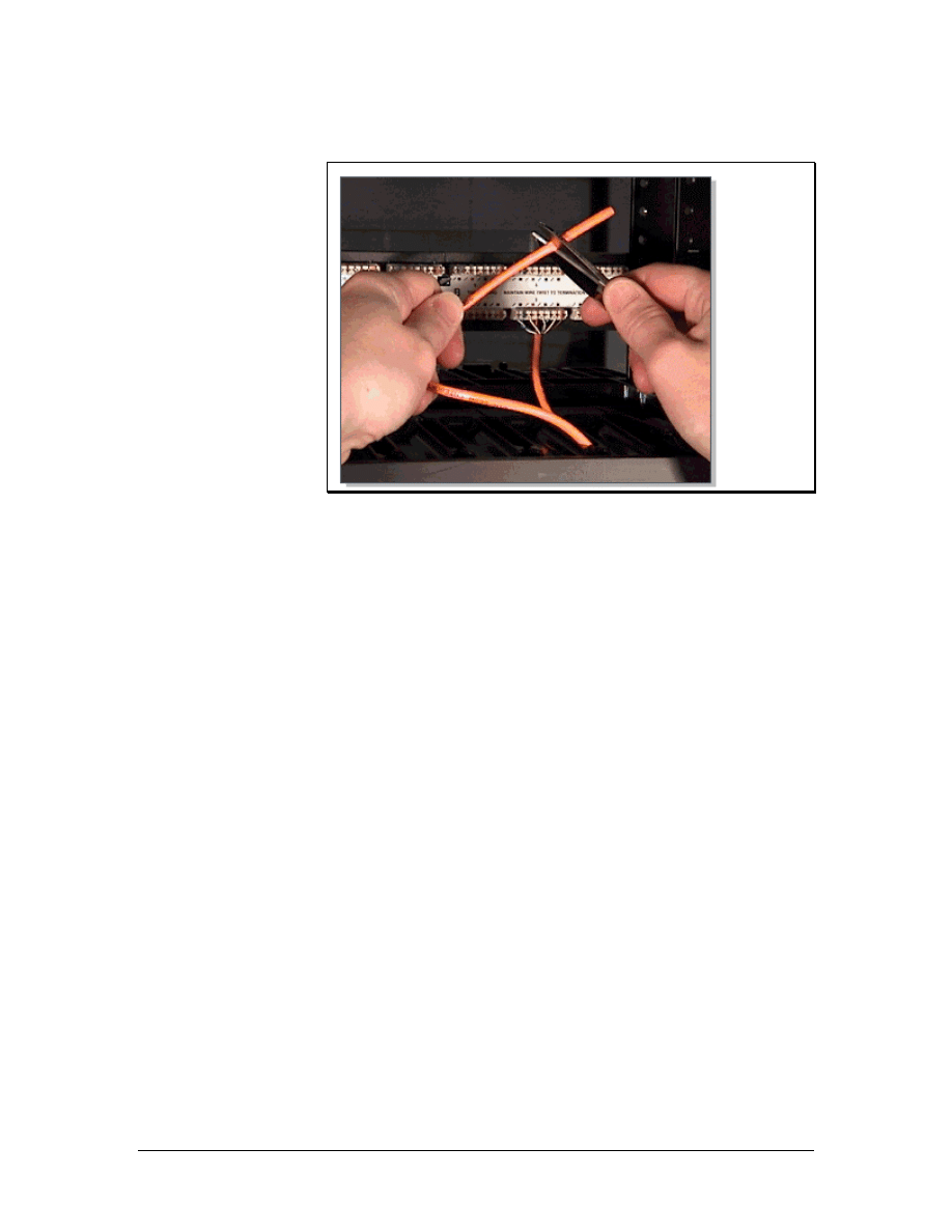
5.5 The Trim Out Phase
Figure 1 Cutting Cable to Length
In the rough-in phase of cable installation, excess cable was left at
both ends of the cable run. These coils of cable are used to take up
slack and facilitate later changes. The coils of cable are known as
service loops. Service loops are discouraged by EIA/TIA standards. It
is not uncommon to have 1 m (3 feet) of ends coming out of a wall
jack at the end of the rough-in stage. A standard TR, where hundreds
of cables are terminated, may have 2 to 3 m (6 to 10 feet) of ends.
Although this may seem wasteful, experienced installers know that an
excess of cable provides more flexibility in cable routing and
provides greater access to cables when toning and testing individual
cables. New installers will commonly cut the cable too short. Excess
cable can always be cut off, but a short cable cannot be extended. If a
cable is too short, the only alternative is to pull another cable. This is
a costly alternative in both labor and time.
If there is 1 m (3 feet) of cable coming out of the wall at the jack
location, it is best to trim this to about 25 cm (10 inches). A new label
should be applied to the cable about 15 cm (6 inches) from the end.
The jacket is then stripped back about 5 to 7 cm (2 to 3 inches) to
expose the individual twisted pairs. The completed jack termination
should have no more than 1.5 cm (0.6 inches) of either unjacketed
conductors or untwist in the cable pairs. Excess conductor length
should be cut off at the final termination, as shown in Figure 1.
The jack is terminated with approximately 15 to 20 cm (6 to 8 inches)
of cable coming out of the wall. This excess cable is carefully coiled
into the wall or wall box when the jack is installed. This excess cable
can be used to reterminate the jack at a later date. It can also be used
to remove the faceplate and add another jack to the outlet. At
69 - 125 CCNA 1: Networking Basics v3.0 – Structured Cabling Supplement
Copyright
2003, Cisco Systems, Inc.
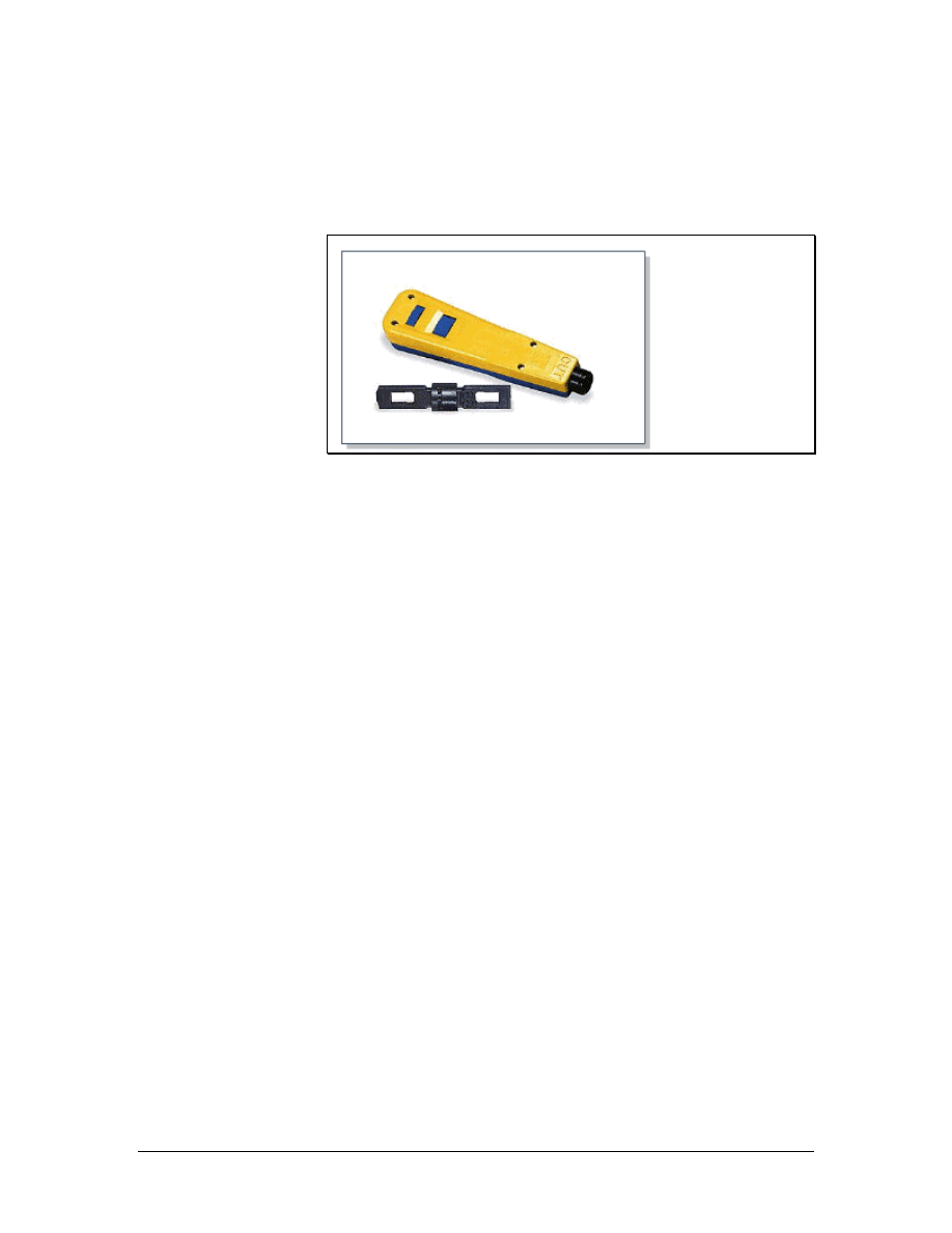
workstation terminations, wires in the jack will commonly lose
contact with the pins. This occurs because the patch cord to the work
area is often pulled, kicked, or stretched by the workstation users.
5.5.1 Terminate or punch down
Figure 1 Removable Termination Blade
The termination of communications cables at a TR is referred to as
punching down. Cables are also punched down on termination panels
mounted on wall fields and at the rear of cross-connect panels.
Wires are inserted into the appropriate locations on termination
panels. Then the punch down tool is placed over the wires.
Depending on the type of termination hardware used, replaceable
blades in the termination tool can be changed out to accommodate the
termination type. A removable blade is shown in Figure 1. When
pressure is put on the tool, spring tension increases to a point where a
firing-pin type mechanism releases the energy stored in the spring.
The wire is instantly forced between two insulation displacement
connections and excess wire is cut off in the same operation. The
connection is referred to as insulation displacement because the
insulation is pushed out of the way by the contacting points on the
terminal.
Insulation displacement connections provide a secure, gas tight
connection. This means that the actual connection is not exposed to
the atmosphere because the displaced insulation presses tightly
against the block. This is necessary to provide long-term, corrosion-
free connections. Patch panels and 110-blocks are typically used for
data networks. 110-blocks are also used for voice applications.
70 - 125 CCNA 1: Networking Basics v3.0 – Structured Cabling Supplement
Copyright
2003, Cisco Systems, Inc.
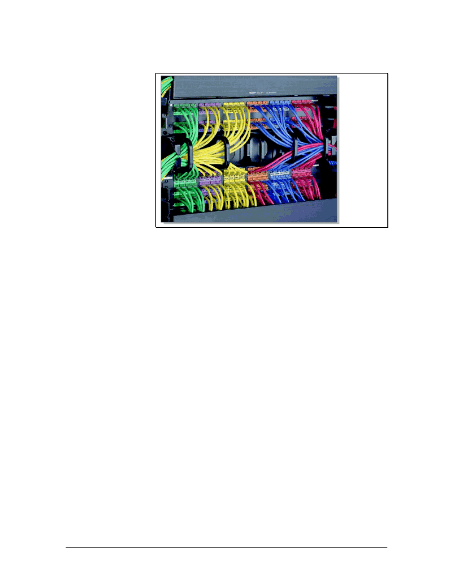
5.5.2 Wire management
Figure 1 Panduit Wire Management
Some termination systems come with a built-in wire management
scheme. 110-blocks use plastic troughs and spacers between blocks.
Troughs can be used both horizontally and vertically. Rack mount
installations incorporate a variety of wire management devices, as
shown in Figure 1. Some use a combination of D-rings and troughs.
When purchasing cable management systems, consider the following:
• The system should protect the cable from pinching and it
should maintain the maximum bend radius.
• The system should be scalable so that it can handle more
cables if necessary.
• The system should be flexible so that cables can enter it from
all directions.
• The system should offer a smooth transition to horizontal
pathways so cable is not damaged and does not exceed the
maximum bend radius.
• The system should be durable enough to last as long as the
cables and the equipment that is mounted on it.
5.5.3 Careful labeling
Labeling is another important part of a structured cabling system.
Cables should be clearly labeled on both ends to avoid confusion.
TIA/EIA-606-A specifies that each hardware termination unit should
have a unique identifier marked on the unit or on its label. When
identifiers are used at the work area, station terminations must have a
label on the faceplate, the housing, or the connector. Most requests
71 - 125 CCNA 1: Networking Basics v3.0 – Structured Cabling Supplement
Copyright
2003, Cisco Systems, Inc.

for proposals and specifications require computer-generated labels.
These labels are permanent, legible, and more professional looking.
Use labels that will be easy to read for many years. Many network
administrators include room numbers in the label information and
assign letters to each cable that leads to a room. Many labeling
systems for large networks also use color-coding.
To ensure that the labels are not rubbed off or cut off in the future,
mark the cable several times at the free end, approximately 60 cm (24
inches) apart. After the cable is run, repeat the procedure at the box or
spool end. Use electrical tape to keep all the cables tied securely
together. Bind the cable ends and the end of a pull string together by
tying some half-hitch knots around the cables with the pull string
before taping the ends. Use a good amount of tape. If the string or
cables pull out in the future, it could be expensive and time-
consuming.
After pulling the cable along the selected route, bring it into the TR.
Pull enough cable for the ends to reach each jack location, plus some
excess cable to reach the floor and extend another 60 to 90 cm (24 to
36 inches).
Return to the spools of cable at the central point or TR. Use the labels
on each spool as a reference. Then mark each cable with the
appropriate room number and letter. Do not cut the cables unless they
have a label. After following these steps, the networking media used
for the horizontal cabling run will be labeled at both ends.
72 - 125 CCNA 1: Networking Basics v3.0 – Structured Cabling Supplement
Copyright
2003, Cisco Systems, Inc.
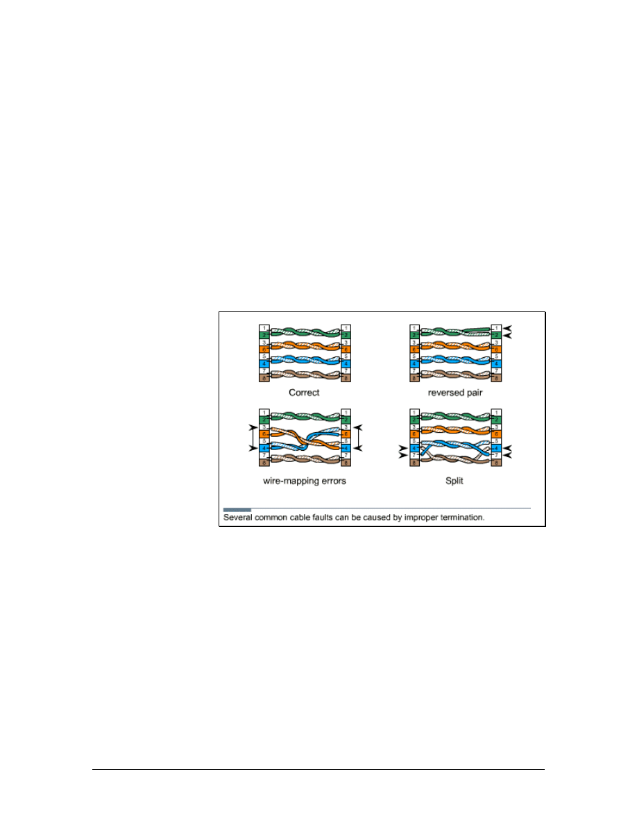
6 Finish Phase
Diagnostic tools are used to identify existing and potential problems
in a network cabling installation.
Cable testers are used to discover opens, shorts, split pairs, and other
wiring problems. After an installer has terminated a cable, the cable
should be plugged into a cable tester to verify that the termination
was done correctly. If a wire is mapped to an incorrect pin, the cable
tester will indicate the wiring mistake. A cable tester should be
included in every cable installer toolbox. After the cables have been
tested for continuity, they can be certified by using certification
meters.
6.1 Cable Testing
Figure 1 Wiring Faults
Testing is the most important step in the finish phase of cable
installation. Testing verifies that all the wires are working properly so
that the customer does not discover problems later. It is better to catch
a problem before it becomes a major issue.
Tests relating to cable function are found in TIA/EIA-568-B.1. The
following common cable faults are shown in Figure 1:
• Opens – Occurs when wires in a cable fail to make a
continuous path from end to end. Opens are usually due to
improper termination, breakage, or faulty cable
• Shorts – Occurs when wires in a cable touch each other and
short the circuit
• Split pairs – Occurs when wires are mixed among pairs
73 - 125 CCNA 1: Networking Basics v3.0 – Structured Cabling Supplement
Copyright
2003, Cisco Systems, Inc.
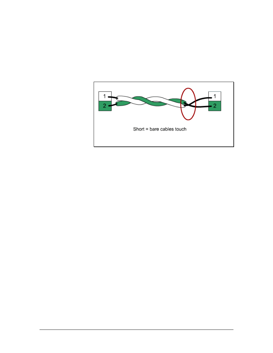
• Wire-mapping errors – Occurs when wires in a multipair
cable do not terminate at the appropriate points in the
connector at the far end
Simple functional testing for opens, shorts, split pairs, and wire-
mapping errors are usually performed from only one end of the cable.
6.1.1 Testing for shorts
Figure 1 Short
A short is formed when two wires in a pair touch each other and
create an undesired shortcut in the signal flow, as shown in Figure 1.
This shortcut completes the circuit before the voltage reaches the
intended target.
To determine if there is a short, measure the continuity or resistance
between the wires. No continuity should be discovered, and there
should be an infinite amount of resistance between them. Use an
ohmmeter with a low-resistance scale to make these measurements.
When a high-resistance scale is used, it may measure the body
resistance of the installer when the wires are held to the probes. Some
installers will create a small test fixture to avoid this problem. Many
test probes can be fitted with slip-on alligator clips. These clips can
hold one of the wires so that both leads are not touched at the same
time.
74 - 125 CCNA 1: Networking Basics v3.0 – Structured Cabling Supplement
Copyright
2003, Cisco Systems, Inc.
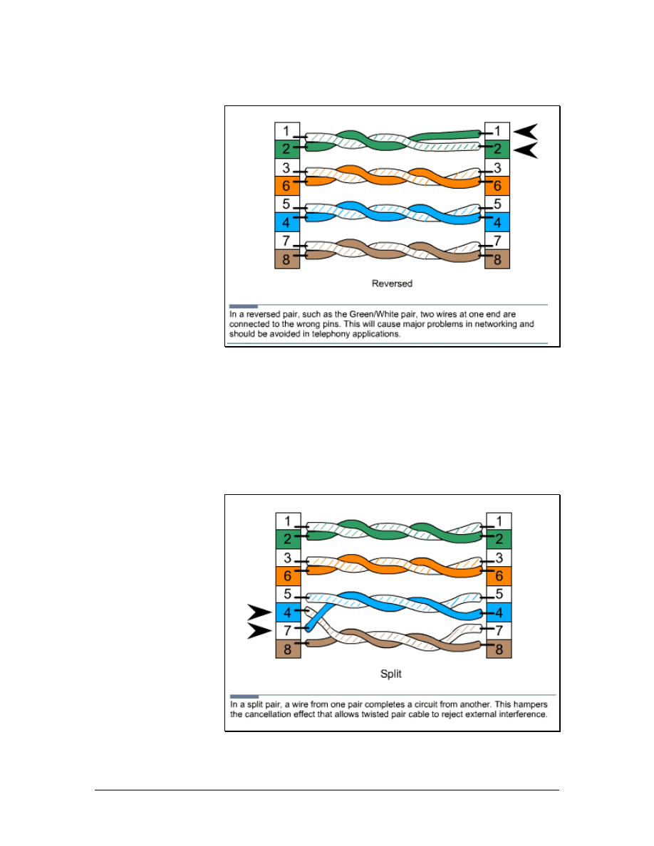
6.1.2 Testing for reversals
Figure 1 Reversal
A reversal occurs when the tip side of a pair is terminated on the ring
position at the opposite end of the wire, as shown in Figure 1.
To repair a reversed pair in a cable, the RJ-45 connector must be
removed and the cable end with the pair reversal must be terminated
again.
6.1.3 Testing for split pairs
Figure 1 Split Pairs
75 - 125 CCNA 1: Networking Basics v3.0 – Structured Cabling Supplement
Copyright
2003, Cisco Systems, Inc.

Split pairs occur when wires are mixed among pairs, as shown in
Figure 1. An ohmmeter can be used to test for splits. First, test the
pairs for shorts. If none are found, place a short across each pair. The
ohmmeter should detect a short. If an open is found, something is
wrong. The pair is either split or open. A tone generator can then be
used to determine whether it is split or open. High-end testers detect
split pairs by measuring crosstalk between pairs.
A simple cable tester can also be used to check for split pairs. This
type of tester uses LEDs that immediately notify the installer if there
is a problem with polarity or continuity.
To repair a split, one or both of the connectors must be removed and
the cable end must be terminated again.
6.2 Time Domain Reflectometer (TDR)
A time domain reflectometer (TDR) sends a pulse down the wire and
then monitors the electronic echoes that occur due to cable problems.
TDRs will determine if there is a cable fault, and whether it is an
open or a short. TDRs can also measure the distance from the meter
to the fault. The signal is reflected back when it reaches the end of the
cable, or anytime it encounters a defect in the cable. The signal speed
is referred to as the nominal velocity of propagation. This is a known
measurement for different cable types. When the tester knows how
fast the signal travels, it can measure the length of the cable by
measuring the amount of time it takes the signal to be sent and
reflected back. A TDR readout is typically calibrated in feet or
meters. If a TDR if properly adjusted and used correctly, it is an
extremely efficient way to identify cable problems.
6.3 Cable Certification and Documentation
Testing is not the same as certification. Testing is for functionality
and determines if the wire can carry the signal from end to end.
Certification, or performance testing, is a statement about cable
performance. Certification answers the following questions:
• How well does the signal travel down the cable?
• Is the signal free from interference?
• Is the signal strong enough at the other end of the cable?
6.3.1 Certification tester
Certification tests for functionality and performance. Structured
cabling systems that adhere to installation standards must be certified.
Certification meters perform all of the required performance tests to
adhere to the ANSI/TIA/EIA-568-B standards. Most meters have an
auto-test function that starts all of the required tests with the touch of
a button. These meters store multiple test results, which are
76 - 125 CCNA 1: Networking Basics v3.0 – Structured Cabling Supplement
Copyright
2003, Cisco Systems, Inc.

downloaded to a computer. A test report is then generated and given
to the customer. In addition to certification, these meters include
diagnostic features that will identify problems and show how far
these problems are from the end of the cable being tested.
Performance testing usually occurs at a designated test frequency.
The frequency is selected to exercise the cable at a speed that will be
part of its intended operation. For example, Category 5e cable is
tested at 100 MHz and Category 6 is tested at 250 MHz. Performance
testing is described in TIA/EIA-568-B. Modern testing hardware and
software can provide both text and graphic output. This allows for
easy comparisons and quick analysis.
The cable certification process forms a baseline measurement for the
cabling system. When the contract is established, a certification
standard is usually included as part of the contract. The installation
must meet or exceed the specifications for the wire grade that is used.
Detailed documentation is used to show the customer that the cabling
has reached these standards. These documents are submitted to the
customer.
The certification procedure is an important step in the completion of a
cabling job. It demonstrates that the cables performed to certain
specifications. Any future change in cable performance will need to
be attributed to a specific cause. It will be easier to figure out what
that cause is if there is documented evidence about the condition of
the cables at an earlier point. Different grades of cable require
different acceptable test results. Higher cable categories generally
have higher manufacturing standards and better performance.
6.3.2 Certification tests
To pass certification, cables must meet or exceed the minimum test
results for their grade. Many actual test results will outperform the
minimum. The difference between the actual test results and the
minimum test results is known as headroom. More headroom
indicates that less cable maintenance will be needed in the future.
These networks are more tolerant of poor grade patch cords and
equipment cables.
The commonly used specifications include the following:
• Specified Frequency Range – Each cable is tested at a
frequency range that will be used in daily service. A higher
grade indicates a higher range.
• Attenuation – The amount of signal that a cable will absorb
is a measure of its attenuation. Lower attenuation indicates
higher-quality conductors and cables.
• Near End Crosstalk (NEXT) – This occurs when signals
from one pair interfere with another pair at the near end of
the cable. Crosstalk can affect the ability of the cable to carry
77 - 125 CCNA 1: Networking Basics v3.0 – Structured Cabling Supplement
Copyright
2003, Cisco Systems, Inc.

data. The amount of NEXT a cable must be able to tolerate is
specified for each grade.
• Power Sum NEXT – When cables use all the conductors,
the signals on one cable interfere with several pairs. To
calculate the effect of these disturbances, the interactions of
all pairs in the cable must be considered. The power sum
NEXT equation measurement does this.
• Attenuation-to-Crosstalk Ratio (ACR) – This ratio
indicates how much stronger the received signal is when
compared to the NEXT or noise on the same cable. This
measurement is also referred to as the signal-to-noise ratio
(SNR), which also accounts for external interference.
• Power Sum ACR – When all of the pairs in a cable are
used, the interaction between the pairs becomes more
complicated. There are more wires are involved so there are
more mutual interactions. The power sum equations help
take this greater mutual disturbance into account.
• Equal-Level Far End Crosstalk (ELFEXT) – This is a
calculated measurement of the amount of crosstalk occurring
at the far end of the wire. If this characteristic is very high,
the cable is not carrying the signals well and the ACR ratio
is not well controlled.
• Power-sum ELFEXT – As with the other power sum
measurements, interaction between multiple pairs in the
same cable increase the complexity of ELFEXT
characteristics. The power sum version of the measurements
considers this.
• Return Loss – Some of the signal that travels down a wire
bounces off imperfections such as impedance mismatches. It
can be reflected back toward the sender and form a source of
interference. This is referred to as return loss.
• Propagation Delay – The electrical properties of the cable
can affect the speed of a signal. The value of this delay is
used to perform certain measurements, such as time domain
reflectometry. Propagation delay for a cable is usually
specified as a maximum allowable amount of delay, in
nanoseconds.
• Delay Skew – Each pair in a cable has a different number of
twists. Signals that enter the cable at the same time will
probably be slightly out-of-sync when they get to the far end.
This is referred to as delay skew. Sloppy termination can
magnify this problem if the cables are asymmetric with
respect to the connector pins. A difference in propagation
delay between the wires in a cable pair can also cause delay
skew.
78 - 125 CCNA 1: Networking Basics v3.0 – Structured Cabling Supplement
Copyright
2003, Cisco Systems, Inc.
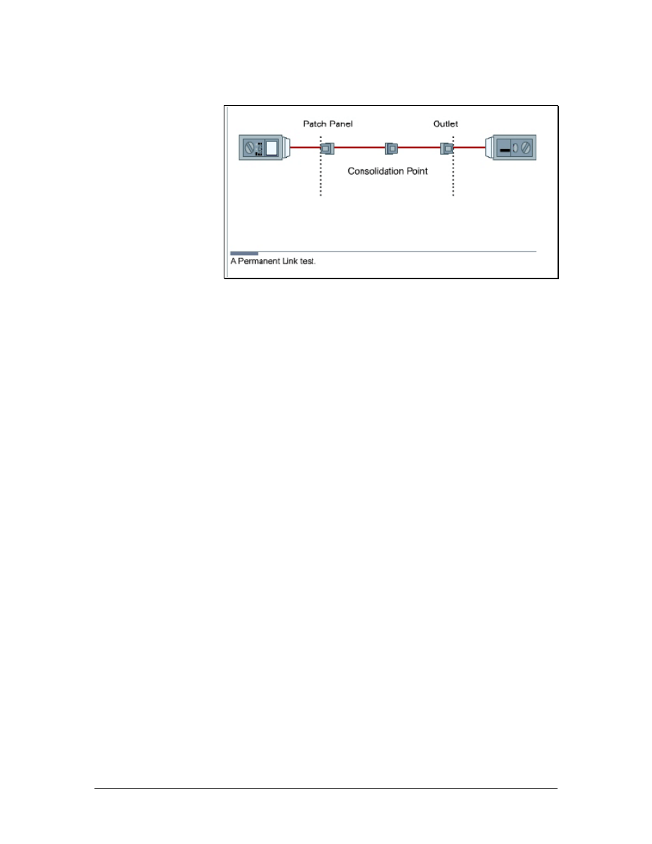
6.3.3 Link and channel testing
Figure 1 Permanent Link Test
The two methods used when testing are the channel test and the link
test. The channel test goes end-to-end from the workstation or
telephone to the device in the TR. The channel test measures all of
the cable and patch cords, including the line cord from the jack to the
user equipment and the patch cord from the patch panel to the
communications equipment. The link test only tests the cable from
the wall back to the patch panel in the TR. There are two types of link
tests. The basic link test measurement starts at the field tester and
ends at the field tester remote unit at the other end of the link. The
permanent pink test excludes the cable portions of the field test units,
but includes the mated connection where the cable is connected to the
adapter cable at each end, as shown in Figure 1. The permanent link
test also allows for a consolidation point. This is desirable for open
office cabling installations and is therefore more practical.
The only accepted test is the permanent link test. The channel test has
been officially eliminated by TIA/EIA-568-B.1.
6.3.4 Certification tips
The interpretation of test results is just as important as the detection
of problems. Installers can learn how to interpret test results by using
test equipment on known good wires and circuits. This will provide a
knowledge base of how to properly use test equipment and how the
test results should appear when the circuits function properly.
To gain experience with troubleshooting and problem identification,
create cables with specific problems. Observe how testers react to
these problems. Practice identifying these problems based on test
results for randomly chosen cables. The time invested in education
will help the installer identify and fix future problems quickly.
79 - 125 CCNA 1: Networking Basics v3.0 – Structured Cabling Supplement
Copyright
2003, Cisco Systems, Inc.
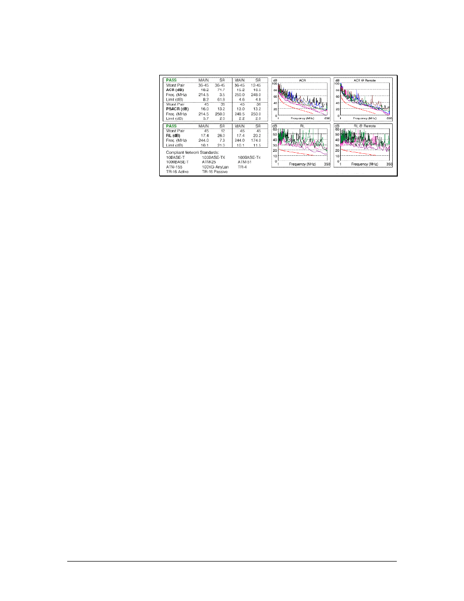
6.3.5 Professional certification documentation
Figure 1 Cable Certification Documentation
Many cable certification tools can export results in a database format.
This can be used in a personal computer to produce high-quality
documents, as shown in Figure 1.
Installation software is generally provided with sophisticated
certification testers. The software will allow the contractor to present
the test result to the customer in an orderly manner. The software
eliminates the need to manually enter the results in a spreadsheet.
Software packages store test results as either pass or fail. When
deficiencies are found and corrected, items are retested and presented
to the customer. Customers generally want both an electronic copy
and a paper copy of the test results.
Documentation must be accessible to be useful. Electronic delivery
ensures that the results are always available when needed. A paper set
of both the as-built documents and the certification results should be
provided to the customer. Installers should retain a copy in their
permanent records.
Certification documentation becomes very important when there is a
question about the quality or accuracy of the wiring job. It shows that
on a specific date, the wires existed in a particular order and could
carry signals at a specified level of quality. Changes in the ability of
the cable to move signals over time can be determined by comparing
current tests to previous results.
Unexpected obstacles, change orders, and last minute equipment
upgrades can affect the documentation. Therefore, the documentation
that was used to construct a network wiring system may not be
representative of the system that was actually constructed. Anytime a
modification is made to the wiring system, it is important to know
what is happening in the system. Otherwise, the changes could have
unpredictable effects. As-built documents can help avoid this kind of
trouble. Always create change documents before any changes are
made.
80 - 125 CCNA 1: Networking Basics v3.0 – Structured Cabling Supplement
Copyright
2003, Cisco Systems, Inc.

6.4 Cutting over
Cutting over is the term used for the transfer of existing services to a
new cable system. It is also used for the installation of new equipment
on a newly installed cable system.
6.4.1 Cutover guidelines
Successful cutovers require careful planning, organization, and
attention to detail. When cutting over, use the following guidelines to
ensure success:
• Keep detailed records of the installation. These records will
verify that all cables have been installed in the correct
locations.
• Test every cable that is installed.
• Develop accurate cut sheets. Cut sheets are a chart of circuits
and the cables on which they operate. The installation
supervisor normally develops cut sheets with information
received from the customer.
• Schedule the cutover when it is most convenient for the
customer. Since cutovers usually require taking some systems
offline, they are often scheduled late at night or on weekends.
6.4.2 Removing abandoned cable
According to the National Electrical Code, edition 2002, all
abandoned cables must be removed when certain criteria defined
within the code are met. Currently, the customer and cable
installation contractor decide whether or not the cost involved in
removing cables is justified. The customer and contractor must be
sure to adhere to the local code. Always check with the local
authority and discuss the details with the customer before beginning
the retrofit.
Before removing any abandoned cable, first verify that there are no
live circuits on the cable by using a multimeter or a telephone test set.
Remove the abandoned cable carefully to avoid damaging ceiling
tiles or dropped ceiling support members.
81 - 125 CCNA 1: Networking Basics v3.0 – Structured Cabling Supplement
Copyright
2003, Cisco Systems, Inc.

7 The Cabling Business
As with most jobs, the appearance and demeanor of cable installers
can affect how customers, bosses, and fellow employees perceive
them. The choices a cable installer makes on the job may result in
promotions or terminations. As an employee, the cable installer
becomes a representative of a company. Therefore, a professional
appearance and demeanor should always be maintained.
When working on a job, use the following guidelines:
• Respect the job site. Be careful to avoid causing damage.
Clean up all messes immediately if they affect other workers
or clean them up at the end of the day.
• Wear clean and neat work clothes to the job site.
• Arrive at an agreed upon time. Punctuality is important.
• Determine the acceptable noise level. Avoid playing music,
whistling, singing, or shouting if working on a retrofit project
while business is being conducted.
• Treat customers, building occupants, coworkers, and bosses
with respect.
7.1 Site Survey
The site survey, or project walk through, is one of the most important
steps before preparing a cost estimate for a project. It allows the
contractor to identify any issues that may affect the installation.
Drawings and specifications supplied by the customer may not
indicate potential problems or complications.
A sketch of the project should be created during the walk through.
The sketch can be used to identify problem areas when performing
the estimate.
There are several key questions to ask during a site survey:
• Are there plenum-ceiling areas?
• Is there a staging and storage area for materials?
• Are special work hours required?
• Are there special safety requirements? This is particularly
relevant in factory environments.
• Which walls are firewalls?
• Is there asbestos in the building?
• Will the customer supply spare ceiling tiles in the event of
breakage?
82 - 125 CCNA 1: Networking Basics v3.0 – Structured Cabling Supplement
Copyright
2003, Cisco Systems, Inc.
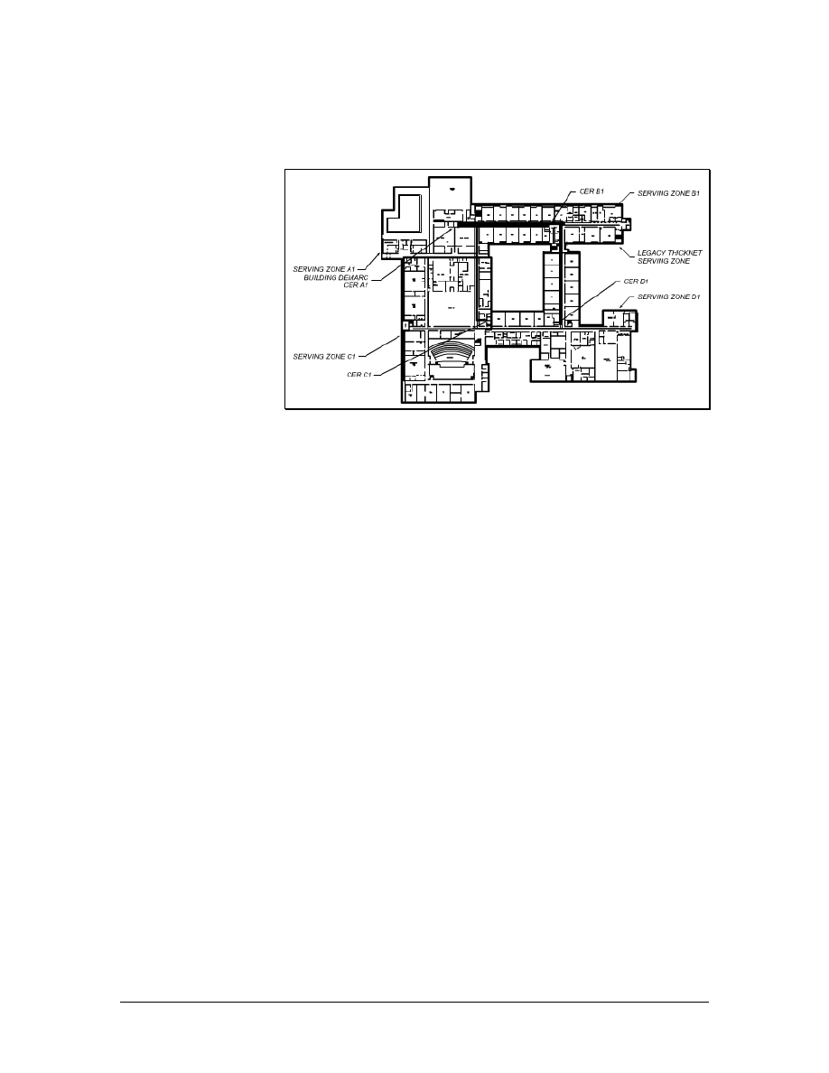
• Are there special labor issues to be considered?
7.1.1 Requirement documents
Figure 1 Typical Building Blueprints
Blueprints are scaled drawings that provide the distance information
required to determine the length of cable runs, as shown in Figure 1.
Blueprints should also show service outlet locations and TRs. Some
blueprints also include available paths or routing information.
However, routing information is generally obtained through a site
survey. Most structured wiring systems specify a minimum of two
four-pair cables per location and many customers specify more. This
information should be duplicated in the specifications for the project.
Count outlet locations and measure cable distances on a blueprint.
These are referred to as take offs. Take offs require a great degree of
accuracy since they are used to determine the material requirements
for a bid. Many automated measuring devices are available to help
automate the process and minimize errors.
83 - 125 CCNA 1: Networking Basics v3.0 – Structured Cabling Supplement
Copyright
2003, Cisco Systems, Inc.
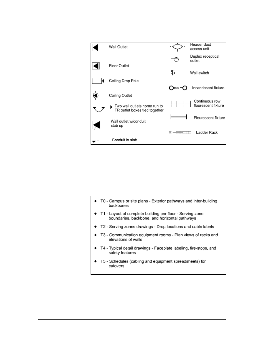
7.1.2 Installation icons and symbols
Figure 1 Cabling Installation Icons
Standard icons and symbols are used on blueprints and schematics to
identify cable runs, raceway types, outlets, and jacks, as shown in
Figure 1. These icons provide a uniform method to graphically
identify requirements on a blueprint.
7.1.3 Drawing types
Figure 1 Types of T Telephone Drawings
Construction blueprints follow a standardized format. Drawings are
grouped according to category and are labeled with a prefix that
identifies the category. For example, all drawings for the electrical
system are grouped together and have the prefix E. Architectural
84 - 125 CCNA 1: Networking Basics v3.0 – Structured Cabling Supplement
Copyright
2003, Cisco Systems, Inc.

sections begin with the letter A and all plumbing begins with a P.
Telephone and data are usually grouped together and are represented
on the T drawings, as shown in Figure 1. Additional drawings, such
as furniture plans, will either be found in the A drawings or in a
miscellaneous category.
The estimator will need the following drawings:
• Site plan for an overview of the project
• Floor plans
• T drawings for telephone placement
• E drawings for electrical reference
• Furniture plans to help determine outlet placement
• A drawings to discover architectural features and available
pathways
Design documents include a narrative about the project. This
narrative may describe the functionality of the cabling system. For
example, it may indicate that the system must support 1000BASE-T
or gigabit Ethernet on twisted pair.
Most design documents include trade jargon and acronyms unique to
an industry or the system being installed. The estimator should
understand all terms in the design document. Glossaries of terms and
acronyms are available on the Building Industry Consultants Service
International (BICSI) website.
Design documents also specify the requirements of the system and
the types of materials that will be used. Information about the number
of cables required per information outlet or jack will also be supplied.
Design documents will also describe testing specifications, labeling
specifications, and formats.
7.1.4 Schematic diagrams
Schematic drawings are not to scale. They are used to depict
connectivity, or the way things are connected. A typical schematic
will show the main TR or MC and the IC. It will also show the type
and size of cables between these points. Most schematics will not
detail the actual terminations at these locations or show individual
cable runs to information outlets or jacks. These schematics will
include cable runs to specific types of equipment like servers or other
major components that are used in a project.
7.2 Labor Situations
Every cable installation company must deal with labor issues. Some
of these issues can cause problems with unions. Installation
companies must be aware of the rules and regulations that apply to
unions and licensing.
85 - 125 CCNA 1: Networking Basics v3.0 – Structured Cabling Supplement
Copyright
2003, Cisco Systems, Inc.

7.2.1 Unions
Some projects may require the use of union labor. Unions are
organizations that represent workers. The use of union labor is more
common for, but not limited to new construction projects. The use of
union labor may be part of a contract. If a customer clearly states that
union labor must be used, the contractor must use union labor.
Other labor situations may dictate the job classification and the work
that is allowed. In a union environment, supervisors are normally not
allowed to perform any installation work and cable installers may not
be allowed to install raceway. Sometimes, cable installers can install
raceway up to a certain size or a certain length and electricians must
install anything beyond that. These rules are defined by a union
agreement, which may be determined by unions of different trades.
7.2.2 Contractor licenses
Some countries do not require contractors to be licensed. In the
United States, contractor license rules vary for different states. Some
states require a contractor license number on all advertising, business
cards, and letterhead. Contractors that operate without a required
license may be fined or lose certain rights. For example, they may not
be able to file a lien if their customers do not pay for services
rendered.
Licensing requirements include technical knowledge, business
knowledge, and knowledge of the labor laws of the state. Contractors
are responsible for knowing if they must be licensed in a particular
state or country.
7.3 Contract Revision and Signing
After all of the negotiations are complete, the contract must be
revised to reflect any agreed-upon changes. The customer and the
contractor must then review the contract in detail. Contract
negotiation is a verbal event that is used to ensure that all intentions
are accurately represented in the written document. Any changes to
the contract while the project progresses are often addressed in
amendments to the contract. Amendments are agreed to and signed by
both the customer and the contractor.
The contract must be signed to become a valid agreement. No
materials should be ordered and no work should begin before the
contract is signed.
A template can be created for common documents such as change
orders. These templates can be brought to the project site and the
information can be entered during the initial meeting or a
walkthrough.
Any changes to a project after it has been started will require a
written change order. No changes to the original plan should be
86 - 125 CCNA 1: Networking Basics v3.0 – Structured Cabling Supplement
Copyright
2003, Cisco Systems, Inc.

started by verbal instructions only. Change orders that result in extra
work should include the cost of the extra labor and materials. If this is
not possible, the change order should state that the customer agrees to
pay for extra work.
7.4 Project Planning
The planning phase of a project may begin before a formal contract is
signed. Information about bidding and estimating is assembled,
special requirements are noted, resource allocations are made, and a
final review of the RFP takes place to make sure that all of the
components are addressed.
The following steps should be taken in this planning phase:
• Select the project manager or supervisor.
• Select crews based on the project size, skills required, and
time allowed for completion.
• Identify and schedule subcontractors.
• Create a material delivery schedule.
• Make provisions for waste disposal.
7.4.1 Suppliers
The estimator will normally select suppliers based on cost, delivery,
and service. The estimator will use the following questions to
determine the total cost of material:
• Does the price include shipping?
• Does the supplier have a history of delivering goods on time?
• What is the policy for returned goods?
• Can the supplier provide cut sheets and engineering drawings
in a timely manner?
• Can the supplier provide technical advice and support?
7.4.2 Ordering materials
After the contract is signed, written purchase orders should be used to
order materials from suppliers. Purchase orders should include a
description of the material, the manufacturer part number, quantity,
price, delivery date, and delivery location.
Generally, the lowest cost supplier that can provide the specified
cable and equipment will be selected. Shipping costs must be
considered to determine the lowest cost. Supplier pricing should
include a guarantee that the pricing will not change for a specified
period of time. Most suppliers will guarantee pricing for at least thirty
87 - 125 CCNA 1: Networking Basics v3.0 – Structured Cabling Supplement
Copyright
2003, Cisco Systems, Inc.
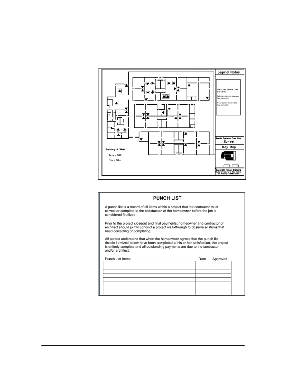
days. The supervisor or lead contractor must make sure that there are
no unapproved substitutions, in an effort to reduce costs.
7.5 Final Documentation
Figure 1 As-Built Drawings
Figure 2 Typical Punch List
It is important to provide as-built drawings to the customer, as shown
in Figure 1. These drawings show cable routes, termination points,
and cable types as they are installed. Some cables may not be
installed as originally planned if obstructions or problems are
88 - 125 CCNA 1: Networking Basics v3.0 – Structured Cabling Supplement
Copyright
2003, Cisco Systems, Inc.

encountered. Typical changes include adding or deleting cable runs or
outlets, or routing cables by a different path.
As-built drawings are not created until all cables are placed, all jacks
are installed, and all cables are terminated. The drawing can begin
during the final testing phase. However, any changes or additional
work must be accurately reflected in the drawings.
Floor plans, furniture plans, or T drawings are usually used as the
basis for as-built drawings. The contractor is not required to redraw
building plans for as-built drawings. The contractor draws all cable
runs, terminations, and outlets and supplies all labeling information.
The punch list is the checklist that the customer provides the
contractor with when the contractor considers the project complete, as
shown in Figure 2. The punch list includes the following items:
• Uncompleted items, such as missing outlets or cable runs
• Unsatisfactory items, such as cables that are not fastened to
ladder racks or outlets that do not work
• Clean up items, such as debris left in the corridor
These items must be corrected prior to final approval and acceptance
of the project. After the items on the punch list are completed,
payment is expected.
89 - 125 CCNA 1: Networking Basics v3.0 – Structured Cabling Supplement
Copyright
2003, Cisco Systems, Inc.

Lab 1: Examination of Termination Types
Objectives
• Review wiring standards T568A, T568B, and RJ-45 USOC.
• Terminate the ends of a Category 5e cable.
Background/Preparation
Bell Telephone established the technique for terminating twisted-pair
cabling. This technique, called the Bell Telephone Universal Service
Order Code (USOC), logically organizes the wires into a modular
plug. Basically, the first pair goes into the center two pins and the
other pairs follow from left to right, splitting each pair down the
middle. This is appropriate for voice technologies, but it can cause
trouble for data, because it separates the wires in the pairs, causing
crosstalk. For this reason, the T568A and T568B wiring standard
were developed. These wiring patterns keep the wires in each pair
together, improving cable performance.
In this lab, identification, preparation, and termination of Category 5e
cable will be learned using the two most popular wiring schemes
found in the ANSI/TIA/EIA standards, T568A and T568B.
Work in teams of 2 to 4 people. Each team will need four Category 5e
cables with a minimum length of 1 m (3 feet) each. The following
resources will be required:
• 4-5 m (13-16 ft) Category 5e cable
• Pan-Plug modular plugs
• Pan-Plug crimp tool
• Wire stripper tool
• Scissors
• Wire snipping tool
• Wire prep tool
• Safety glasses
• Fluke 620 cable meter or LinkRunner
Optional: USOC wiring schematic
URLs
Safety
Wear safety glasses at all times during this lab.
90 - 125 CCNA 1: Networking Basics v3.0 – Lab 1
Copyright
2003, Cisco Systems, Inc.
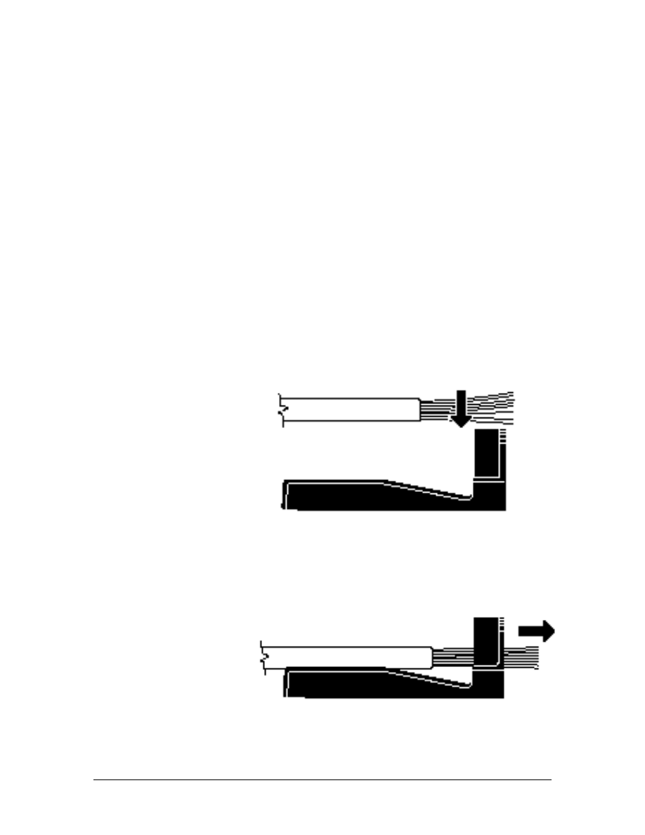
Step 1 Removing the Cable Sheath
a. Use a ruler and measure 8 cm (3 inches) from the end of the
cable. Put a mark on the cable.
b. Use the wire stripper tool to carefully score the outer sheathing of
the cable without fully cutting through to the conductors. Cut off
as close possible to the marked length and remove the cut
sheathing.
Do not nick any of the insulators.
Note: Notice on the stripping tool that there is a minimum or
maximum cutting direction. Use the minimum cutting direction. Do
not make more than two 360-degree turns with this tool.
Step 2 Fan the Four Pairs
a. Untwist each of the cable pairs. Take care not to untwist more
than is needed, as the twisting provides noise cancellation.
b. Keep the individual pairs grouped together for ease of
identification. This is helpful because some tip wires may not
have any visible trace of color and may appear to be solid wires.
c. Use the wire prep tool and insert the conductors individually in
the proper sequence using the T568A or T568B wiring scheme.
Note: The top of the arrow in the above diagram will be pin 1 and 2,
White/ Orange and Orange.
d.
Pull the conductors until cable jacket is at the conductor retention
slot.
91 - 125 CCNA 1: Networking Basics v3.0 – Lab 1
Copyright
2003, Cisco Systems, Inc.
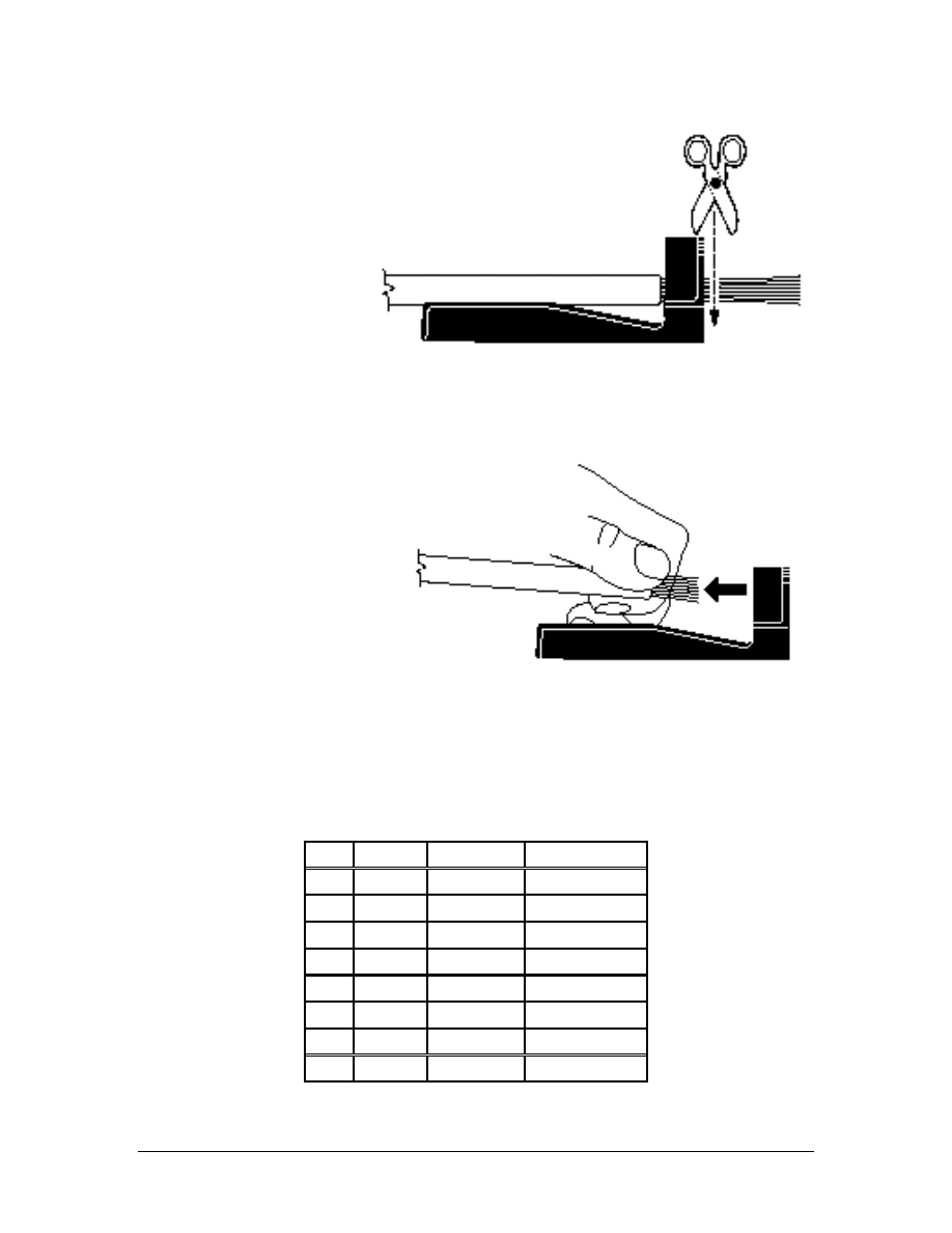
e. Trim the conductors flush with the wire snipping tool.
.
f. Remove the cable from the conductor retention slot, keeping the
conductors held in position by placing thumb and forefinger at
the cable jacket end.
Step 3 Terminating a Plug with T568A Wiring Standard
T568A Schematic
Pin#
Pair#
Function
Wire Color
1 3 Transmit
White/Green
2 3 Transmit Green
3 2 Receive
White/Orange
4 1 Not
used Blue
5 1 Not
used
White/Blue
6 2 Receive Orange
7 4 Not
used
White/Brown
8 4 Not
used Brown
92 - 125 CCNA 1: Networking Basics v3.0 – Lab 1
Copyright
2003, Cisco Systems, Inc.
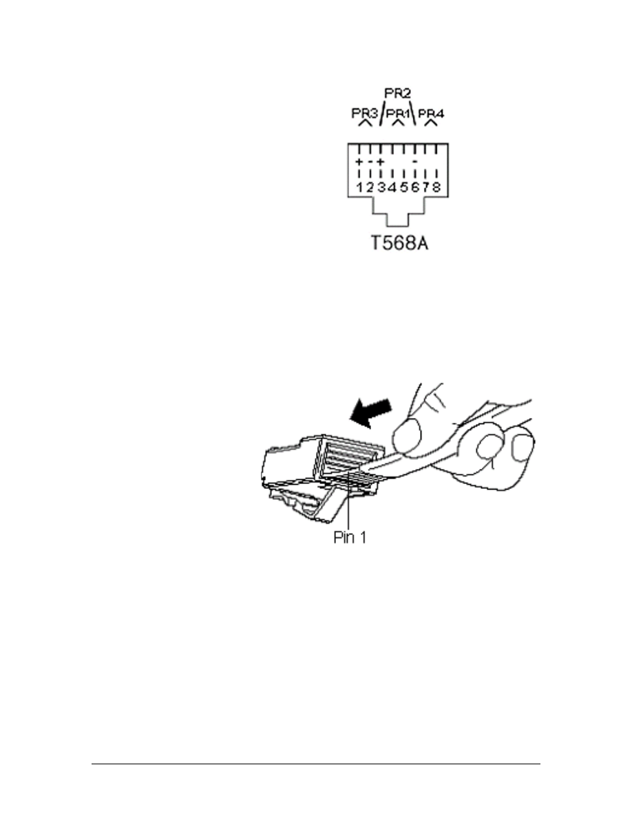
Note: Shown here is a diagram of an RJ-45 jack. Notice that the plug
will fit with the key toward the bottom of the jack. Positioning the
plug with the key pointed away from you when inserting the
conductors will ensure that pin 1 will start on the left and proceed to
pin 8 on the right.
a. Terminate one side of the cable using the T568A standard.
b. Apply a slight downward pressure as the conductors are inserted.
Apply slight pressure until they are fully inserted and under the
plug contacts at the top of the plug.
93 - 125 CCNA 1: Networking Basics v3.0 – Lab 1
Copyright
2003, Cisco Systems, Inc.
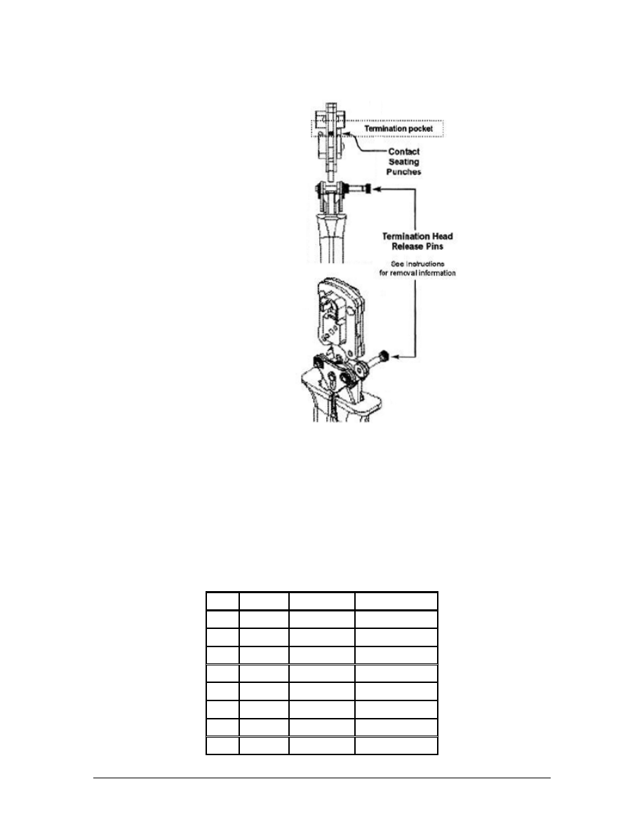
Place the plug into the die until it clicks.
c. Complete the termination by closing the handles fully and then
releasing them.
Step 4 Terminating a Plug with T568B Wiring Standard
a. Repeat Steps 1 through 3.
T568B Standard
94 - 125 CCNA 1: Networking Basics v3.0 – Lab 1
Copyright
2003, Cisco Systems, Inc.
Pin#
Pair#
Function
Wire Color
1 2 Transmit
White/Orange
2 2 Transmit Orange
3 3 Receive
White/Green
4 1 Not
used Blue
5 1 Not
used
White/Blue
6 3 Receive Green
7 4 Not
used
White/Brown
8 4 Not
used Brown
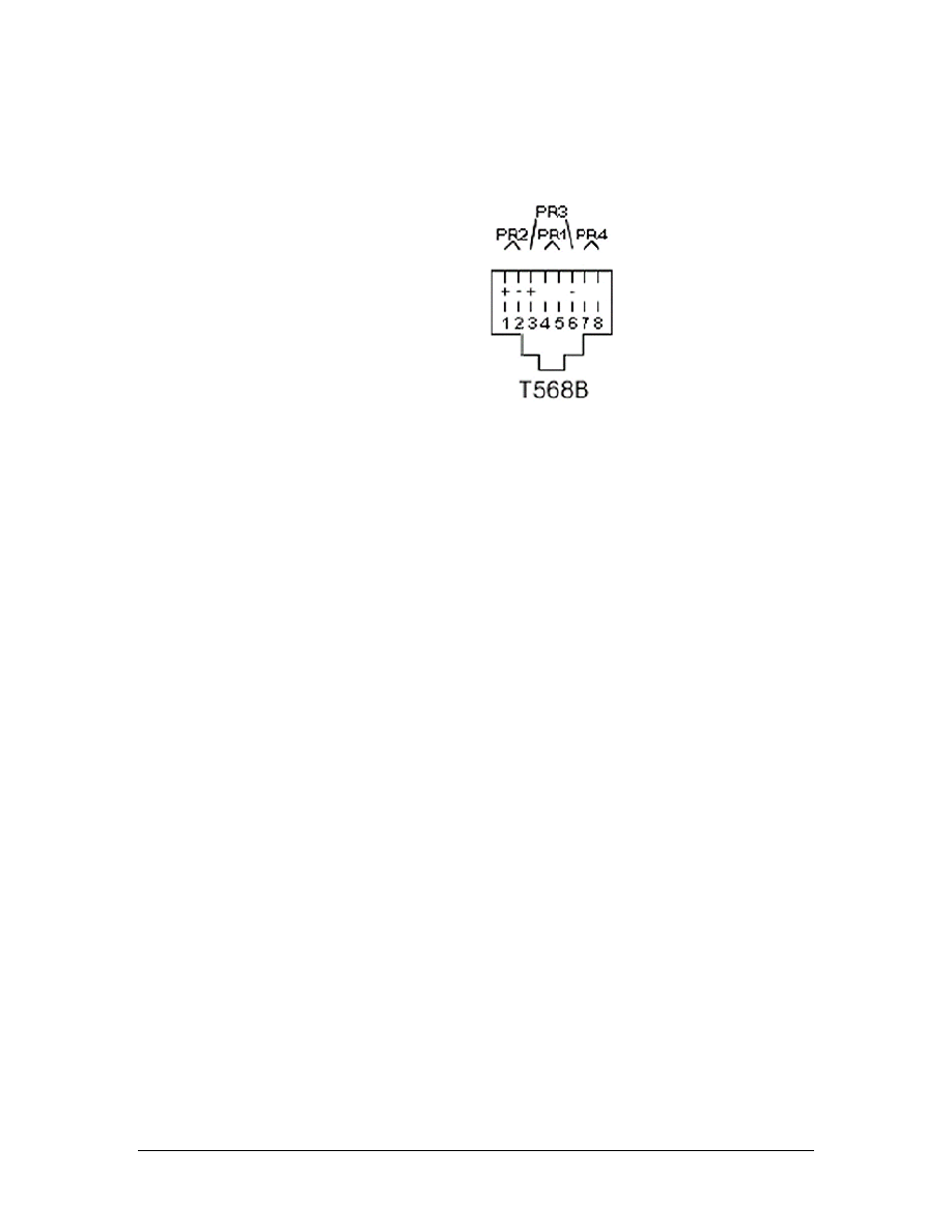
b. Once both ends of the cable have been completed, have a team
member review the wiring standards to ensure that the plugs are
correctly terminated.
Step 5 How To Decide Which Wiring Standard To Use
a. When deciding which wiring standard to use, ask these questions:
■
Does the job specification require a certain wiring standard?
■
Has it already been established by the existing cabling?
■
Does the new wiring match the existing wiring?
■
Has the customer specified a wiring standard?
■
Have patch panels already been purchased for the job? If so, they
will probably be either T568A or T568B. The jacks should be
wired to the same standard as the panels.
b. If none of the previous factors apply, either T568A or T568B
may be used. It is important to ensure that the workstation
connectors and the patch panels are wired to the same standard.
In the United States, T568B is commonly used in commercial
installations, while T568A is the standard in residential
installations.
Step 6 Testing
a. Use the Fluke 620 cable meter or LinkRunner to test the jack
installation.
What are the results of the test?
________________________________________________________
________________________________________________________
b. Are the results exactly the same when the second jack is tested?
________________________________________________________
95 - 125 CCNA 1: Networking Basics v3.0 – Lab 1
Copyright
2003, Cisco Systems, Inc.
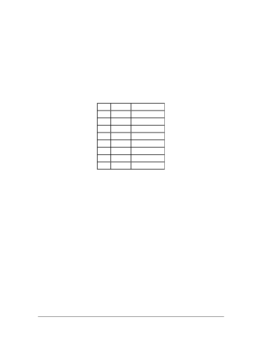
c. Why or why not?
________________________________________________________
________________________________________________________
Step 7 Clean Up
Ensure that all tools are properly stored, and that all trash and debris
has been removed from the work area.
RJ-45 USOC Schematic
Pin#
Pair#
Wire Color
1 4 White/Brown
2 3
Green
3 2 White/Orange
4 1
Blue
5 1 White/Blue
6 2 Orange
7 3 White/Green
8 4 Brown
USOC is an old standard used for voice cabling. For phones with one
or two lines, which use pins 4/5 and 3/6, T568A or T568B will work
just as well as USOC. However, for Ethernet, pins 1/2 and 3/6, USOC
will not work. An Ethernet NIC trying to transmit on pins 1/2 will not
work because 1/2 is not a pair, they are not the same color and not
twisted together. The USOC code is not recognized by the Standards,
however it is common in the termination of T1 circuits.
96 - 125 CCNA 1: Networking Basics v3.0 – Lab 1
Copyright
2003, Cisco Systems, Inc.

Lab 2: Terminating a Category 5e Cable on a
Category 5e Patch Panel
Objectives
• Terminate a Category 5e cable on a Category 5e patch panel.
• Proper use of the 110-punch-down tool.
• Proper use of the cable stripper.
Background/Preparation
A Category 5e patch panel is a device that is used to terminate wires
in a central location. Cables from local data and voice networks are
collected in one patch panel, and cables from the outside are collected
in a separate panel. These two panels provide a way to connect the
two collections of wires in order to supply connectivity from outside
the building all the way to the desktop. This system of wire
management allows for organization and quick changes.
In this lab, a Category 5e cable will be terminated on a patch panel.
The other end of the cable will be terminated on a 110-connection
block.
The instructor or lab assistant will designate the location of the
punch-down for each student at the top of this sheet indicating the
rack, row, and position on the patch panel. Work in teams of 2 to 4
people. The following resources will be required:
• Category 5e patch panel
• 1.2 m (4 ft) of Category 5e UTP cable
• Wire stripper tool
• Wire snipping tool
• Impact tool with 110 cutting blade
• C4 clips
• 110 to RJ-45 adaptor cable
• Fluke 620 or LinkRunner
• Safety glasses
URL
Safety
Remember to always wear safety glasses when punching down wires.
Always be conscious of the task being performed to avoid accidental
cuts.
97 - 125 CCNA 1: Networking Basics v3.0 – Lab 2
Copyright
2003, Cisco Systems, Inc.
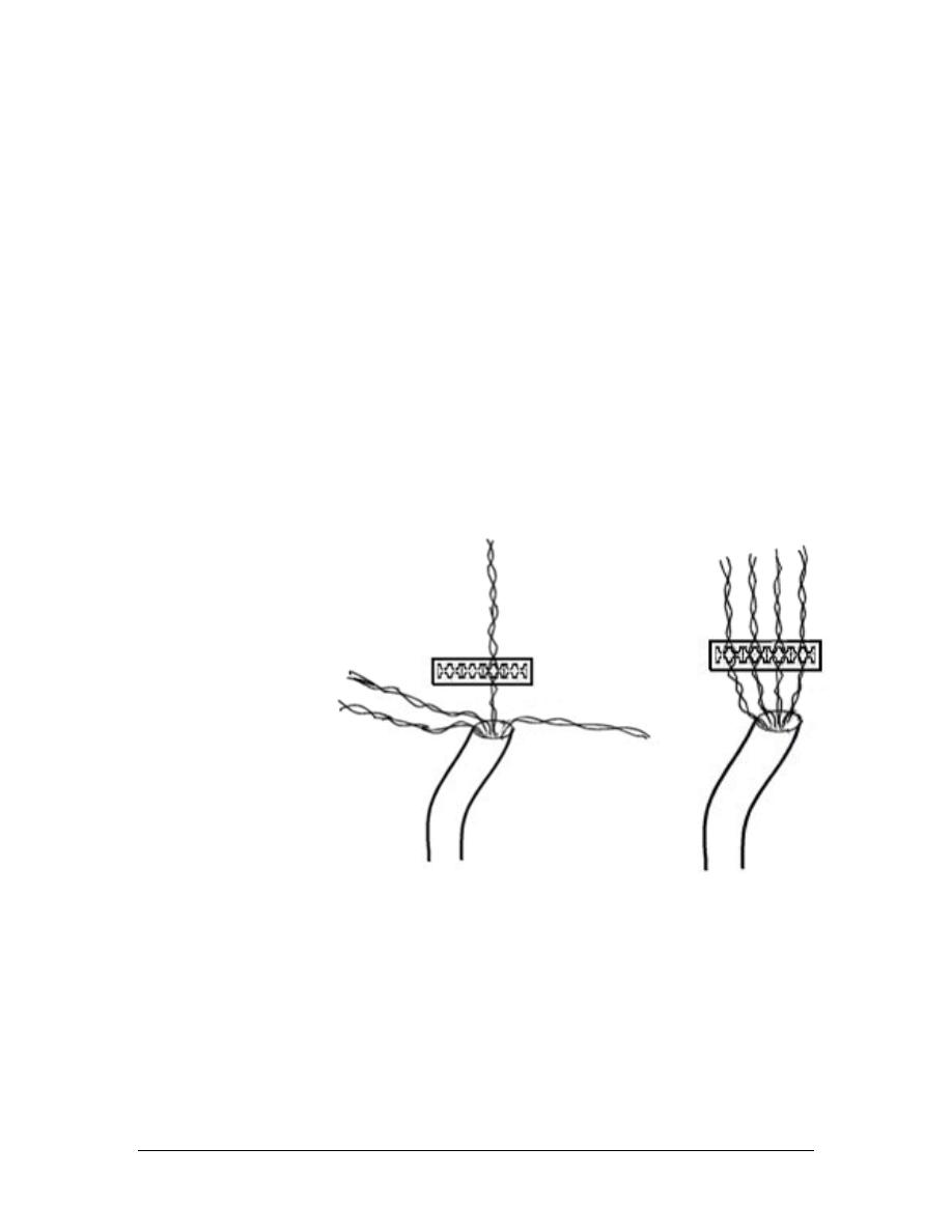
Step 1 Cable Preparation
Remove enough of the sheath to terminate the cable on the patch
panel.
Step 2 Insert the Conductors
a. Fan out the conductor pairs without untwisting the wires at all.
b. Follow the label on the rear of the patch panel. Cables will be
terminated as T568B.
c. Make sure to have 8-10 cm (3-4 inches) of extra wire past the
termination point and split a twist on the colored tip. The tip color
goes to the left and the ring color goes to the right. This will
ensure that the twisting continues up to the point of termination.
It is very important that the twists in the wire remain as tight as
possible up to the point of termination.
Note: The maximum untwist length for Category 5e cable is 1 cm
(0.5 in).
d. To make sure the termination of the cable looks professional, it is
best to begin the insertion of the conductors with the center pairs
and work towards the outside termination points. This will
provide the outside wire pairs a minimal and equal amount of
exposure.
Step 3 Punch Down
Note: If the patch panel is punched down on too hard, the circuit
board inside may be damaged. The single wire impact tool with the
110-blade should only be used for this application. The impact tool
98 - 125 CCNA 1: Networking Basics v3.0 – Lab 2
Copyright
2003, Cisco Systems, Inc.
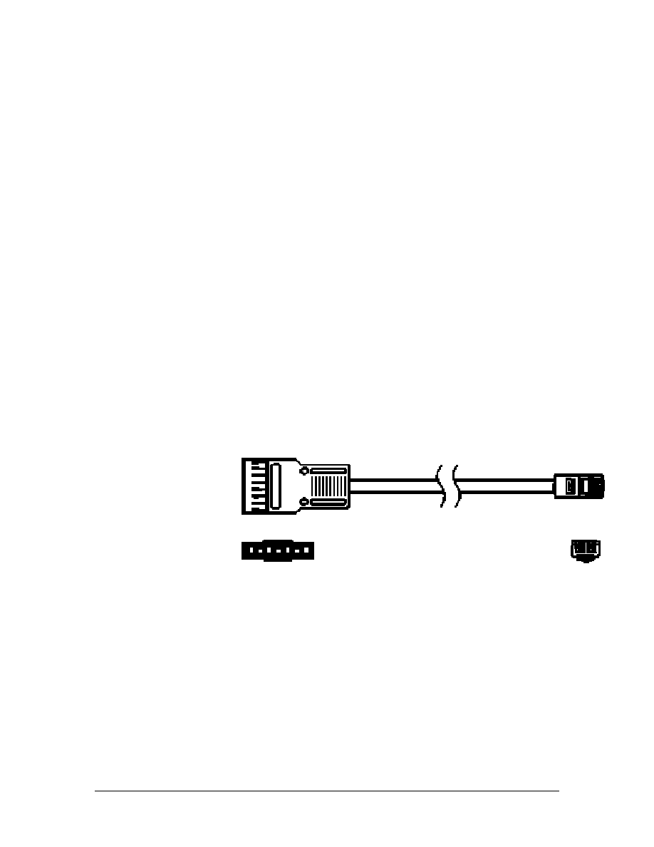
should be set on the “lo” setting. Never use the multipunch tool when
terminating on a patch panel.
a. Position the impact tool over the wire with the blade facing
toward the end of the wire and press firmly on the impact tool
until it clicks. Do not hit the tool with the hand to punch down the
wires. With the impact tool set to “lo”, it may be necessary to
punch the wire two or three times to insure a proper termination.
b. Follow steps 2 and 3 for the other wire. Gently remove the excess
wire.
c. Repeat this step for each pair of wires.
Step 4 110 Panel
a. Strip 7.5 cm (3 in) from the other end of the cable and terminate
it on the designated row and position of 110-connection block
AA or BB-5. This block is located on the relay rack.
b. Install a C4 clip over the Category 5e cable using the multipair
termination tool.
Step 5 RJ45 to 110 Adapter Cable
a. An RJ-45-to-110 adapter cable is a cable with an RJ-45 connector
on one end and a connecter that will plug into a 110-panel on the
other end.
b. Will this cable test as a straight cable, or a cross over cable?
________________________________________________________
c. Explain
why.
________________________________________________________
________________________________________________________
________________________________________________________
99 - 125 CCNA 1: Networking Basics v3.0 – Lab 2
Copyright
2003, Cisco Systems, Inc.

d. Snap the adapter over the installed C4 clip. Using the Fluke 620
or LinkRunner, test the cable between the patch panel and the
110-connection block.
e. What are the results of the test?
________________________________________________________
________________________________________________________
f. Was the initial assumption correct?
________________________________________________________
Step 6 Clean Up
Ensure that all tools are properly stored. Remove all trash and debris.
100 - 125 CCNA 1: Networking Basics v3.0 – Lab 2
Copyright
2003, Cisco Systems, Inc.

Lab 3: Tool Usage and Safety
Objectives
• Identify the tools that are used in cable installations.
• Examine and handle the tools that are used in cable
installations.
Background/Preparation
The type of cable that is being installed determines the tools that are
needed for a job. Proper tools are required to install cables correctly
and safely. While not every tool will be used in every cable
installation job, it is important to know about most of the tools and
supplies that may be used to ensure quality installations and to
complete the jobs in a safe and timely manner.
Safety is a consideration for every task. It is critical that precautions
are taken to ensure that the job is done safely. Knowing how to use
the tools will help prevent injury to people.
The purpose of this lab is to identify the commonly used tools and
supplies that can be used in cable installation jobs and learn how to
use them safely. Keep in mind that the names of some tools may vary
between regions and countries and installers often use nicknames for
some tools. Work in teams of 2 to 4.
Warning: Instructor MUST be present during this lab. Some of
the tools introduced in this lab are very dangerous. Before
handling each tool, read the section in the lab that corresponds
to the tool. The section will review how each tool works and
review any safety measures that must be followed.
The following resources will be required:
• Cutting tools
• Terminating tools
URLs
http://www.du.edu/risk/Tool_Safety.html
http://siri.uvm.edu/ppt/handsafe/handsafety.ppt
101 - 125 CCNA 1: Networking Basics v3.0 – Lab 3
Copyright
2003, Cisco Systems, Inc.

Step 1 Cutting Tools
Handle all of the tools listed. Simulate how they would be used in the
field.
Panduit Wire Stripper Tool
The Panduit wire stripper tool is used to remove the outer sheath
from Category 5e cable and small coaxial cable. The tool is pulled
apart to retract the cutting blade. Cable is inserted into the hole and
the installer releases the blade. The tool is spun around the cable one
turn. It turns in a clockwise direction for cables with thinner jackets
and counter clockwise for cables with thicker jackets. The tool is
then spread apart to remove the tool. Do not use the tool to pull the
jacket off. By dragging the tool over the exposed wires, they can be
cut and damaged. The jacket can now easily be pulled off. Because
this is a cutting tool, safety glasses should be worn when using this
tool.
Electrician’s Scissors
102 - 125 CCNA 1: Networking Basics v3.0 – Lab 3
Copyright
2003, Cisco Systems, Inc.
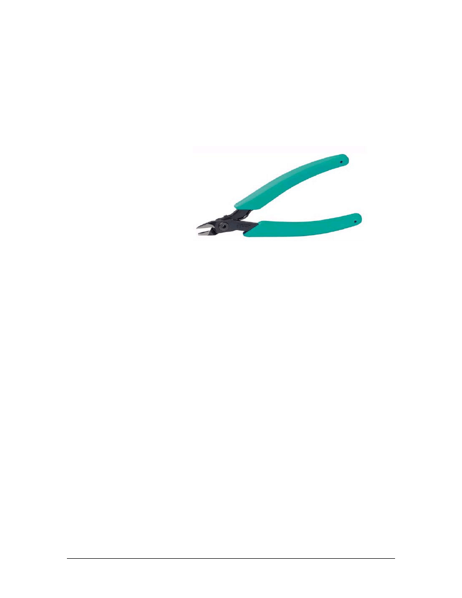
Electrician’s scissors, also known as “snips”, can be used for cutting
Category 5e cable and miscellaneous wire on an installation project.
There are two notches on one of the blades. These notches are used to
skin insulation from individual conductors. The scissors can also be
used for scoring cable jackets. As with other cutting tools, care should
be taken not to pinch fingers between the handles or cut fingers.
Always wear safety glasses when using snips.
Panduit Wire Snipping tool
a. The Panduit wire snipper tool is used for cutting excess wire when
installing a TX Mini-Jack. The tool will cut copper conductors flush
with the termination cap. The wire snipper tool should not be used for
cutting Category 5e cables. It is designed for cutting individual cable
pairs only. This tool is very sharp and care should be taken when using
it. Remember to be careful of the sharp tips on the blades as well. As
with all cutting tools, safety glasses should be worn when using this
tool.
b. How many times is the cable-stripping tool rotated to remove a cable
jacket?
____________________________________________________________
c. Which cutting tools require safety glasses when using?
____________________________________________________________
____________________________________________________________
Step 2 Termination Tools
Handle all of the tools listed. Simulate how they would be used in the
field.
103 - 125 CCNA 1: Networking Basics v3.0 – Lab 3
Copyright
2003, Cisco Systems, Inc.
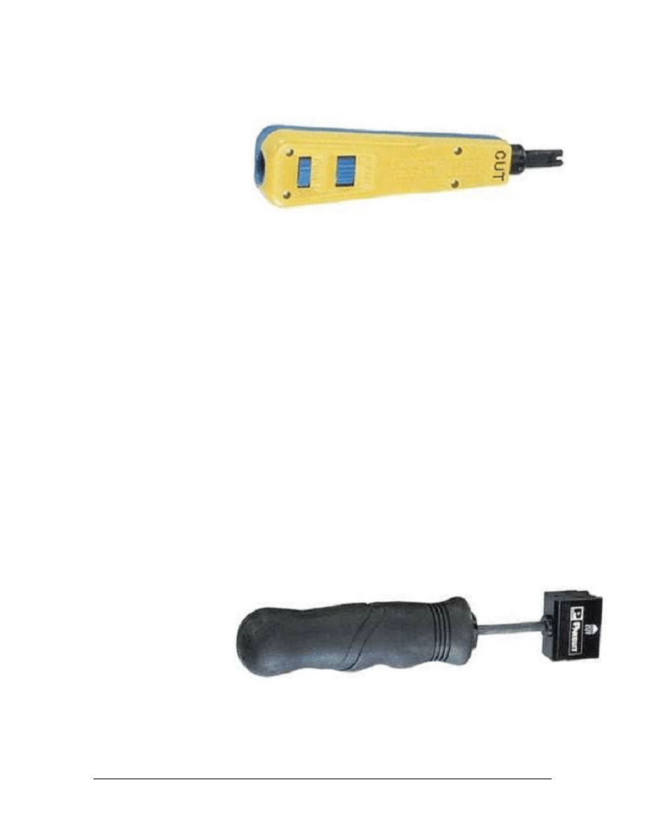
Panduit Single Pair Punch Tool
The single pair punch tool is used for terminating cable pairs on
termination blocks and on the back of patch panels. The tool will
accept blades from all of the popular termination panels. The tool in
the lab is equipped for terminating cable pairs on 100-blocks. The
blade is reversible. It has a cut position on one side. In this
configuration, the tool will punch down a wire and cut off the excess
wire in a single motion. The other side of the blade will punch down
without cutting. The cutting side is marked on the body of the tool.
Blades are removed by twisting the blade counter clockwise and
pulling the blade out of the tool. To install the blade, insert it into the
tool and twist clockwise. Be careful when using this tool or changing
the blades because the small blade on the end can cause cuts.
A wire is inserted into its slot in a termination panel. Grasp the tool
by the handle. Keeping the tool perpendicular to the block, push the
blade over the wire. This is an impact tool. As the handle is pushed,
spring tension increases until the tool snaps and releases the energy of
the compressed spring. The wire is completely seated into its position
and the excess wire is cut off. The tool features an adjustable impact
setting.
Panduit Multi-Pair Punch Tool
The multi-pair punch tool is used to insert conductors on 110-blocks.
The tool will insert and cut five pair at one time. The tool is also used
to terminate three, four, or five 5-pairs of conductors at a time by
104 - 125 CCNA 1: Networking Basics v3.0 – Lab 3
Copyright
2003, Cisco Systems, Inc.
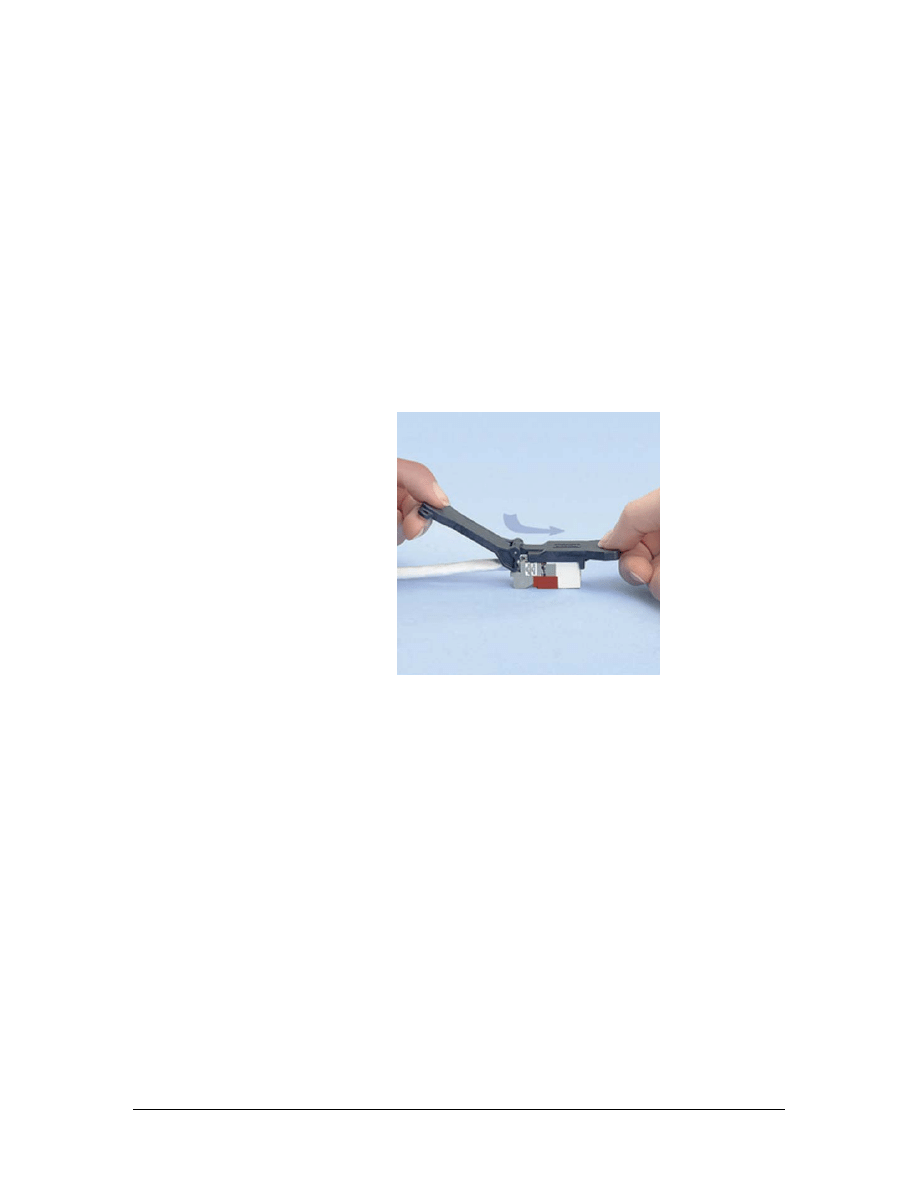
seating “C” clips over them after they have been inserted. The multi-
pair punch tool features reversible and replaceable cutting blades. By
twisting the head of the tool, a detent is released and the head can be
removed from the tool. Cutting blades are slid out from the side of the
head. The blades can be installed facing forward for cutting, or facing
backward for seating “C” clips. Be very careful with this tool because
it has numerous small blades that can cause cuts. The tool is used in a
fashion similar to the single pair punch tool. Multiple pairs are
inserted in the block, the tool is placed over the pairs, and the installer
pushes on the tool until the energy in the spring is released in a sharp
impact. This is a high impact tool and is not suitable for use on the
back of patch panels.
TX Mini-Jack Termination Tool
a. The TX Mini-Jack termination tool is used to press the
termination cap into a TX Mini-Jack. The termination tool
assures a proper and uniform installation of the termination cap
into the jack.
b. Describe the difference between the two ends of the blade on the
110-punch tool.
________________________________________________________
________________________________________________________
c. How is the blade removed on the multi-pair punch tool?
________________________________________________________
________________________________________________________
105 - 125 CCNA 1: Networking Basics v3.0 – Lab 3
Copyright
2003, Cisco Systems, Inc.

d. How is the blade removed on the 110-punch tool?
________________________________________________________
________________________________________________________
e. Why does the multi-pair punch tool have a reversible blade?
________________________________________________________
________________________________________________________
f. Why does the 110-punch tool have a reversible blade?
________________________________________________________
________________________________________________________
g. What tool is used to terminate a mini-jack?
________________________________________________________
h. Can the multi-pair punch tool be used at the back of a patch
panel? Why or why not?
________________________________________________________
________________________________________________________
106 - 125 CCNA 1: Networking Basics v3.0 – Lab 3
Copyright
2003, Cisco Systems, Inc.
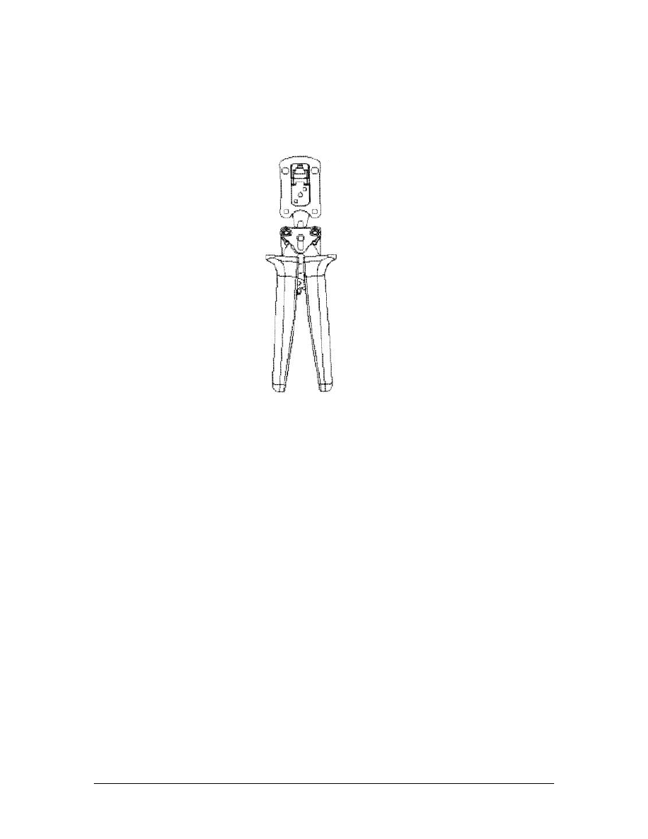
Step 3 Crimp Tools
Panduit RJ-45 Crimp Tool
a. The RJ-45 crimp tool is used for installing RJ-45 connectors on
the end of a cable. Wires are inserted into the connector following
the proper color code. The connector is inserted into the tool until
the connector “clicks” into place. The handles of the tool are
squeezed completely until they release. This is a ratcheting tool,
so the handles will not return to their full open position until the
tool fully closes. Keep fingers out of the open jaws of the tool.
There is a release lever between the handles of the tool that will
allow the jaws to open without fully closing them. This is a safety
feature.
b. What are the two ways used to open the RJ-45 crimp tool?
________________________________________________________
________________________________________________________
107 - 125 CCNA 1: Networking Basics v3.0 – Lab 3
Copyright
2003, Cisco Systems, Inc.

Lab 4: Identification of Cables
Objectives
• Identify the different types of cables used in this course.
Background/Preparation
Category is the term used to distinguish the grades of twisted-pair
cables. Each grade is distinguished by the number of wires in the
cable, the number of twists of the wires, and the speed of data
transmission that can be accommodated. This lab will identify several
categories of copper cables.
The instructor or lab assistant will prepare 0.3 m (1 foot) - 0.6 m (2
feet) lengths of each type of cable listed below. Strip off 15 cm (6
inches) of the outer sheathing at one end of the cable so that the
construction of the cables can be examined.
Notice that there is a minimum and maximum cutting edge on the
cable-stripping tool. Use the minimum cutting edge to insure that the
conductors are not nicked. Make sure a maximum of two 360-degree
turns are used with the cable-stripping tool to prevent nicking the
conductors. Work in teams of 4 to 5 people. The following resources
will be required:
• Category 5e UTP stranded-conductor cable
• Category 5e UTP solid-conductor cable
• Category 6 UTP stranded-conductor cable
• Category 6 UTP solid-conductor cable
• Cable stripping tool
• Tape measure
URL
Step 1 Examining Category 5e UTP solid-conductor cable
a. Select the Category 5e UTP solid-conductor cable by inspecting
the cable jacket. It identifies the type of cable.
b. What is the marking on this cable?
_______________________________
c. Examine the inside structure of the cable.
d. How many pairs are in the cable?
________________________________
e. What is used to help identify a particular wire?
__________________
108 - 125 CCNA 1: Networking Basics v3.0 – Lab 4
Copyright
2003, Cisco Systems, Inc.

f. Examine the individual wires.
g. How many strands of copper are within each wire?
_____________
Step 2 Examining Category 5e UTP stranded-conductor cable
a. Select the Category 5e UTP stranded-core cable.
b. Does the outer jacket differ from that of the Category 5e UTP
solid-conductor cable?
________________________________________________________
c. What is the marking on this cable?
________________________________________________________
d. Examine the internal construction of the cable.
e. How does it differ from the Category 5e UTP solid-conductor
cable?
________________________________________________________
f. How many strands of copper are within each wire?
________________________________________________________
Step 3 Examining Category 6 solid-conductor cable
a. Select the Category 5e STP stranded-core cable. Inspect the cable
carefully, and note that the cable’s jacket identifies the type of
cable.
b. What is the marking on this cable? ________________________
c. Examine the internal construction of the cable.
d. How does it differ from a Category 5e UTP cable? ___________
e. How many layers of shielding does it have? _________________
f. How many strands of copper are within each wire? ___________
Step 4 Examining Category 6 UTP stranded-conductor cable
a. Select the Category 6 UTP stranded-conductor cable.
b. What is the marking on this cable? ________________________
c. Examine the internal construction of the cable.
d. How many pairs are in the cable? _________________________
e. How does it differ from a Category 5e UTP cable? ___________
f. How many layers of shielding does it have? _________________
g. How many strands of copper are within each wire? ___________
109 - 125 CCNA 1: Networking Basics v3.0 – Lab 4
Copyright
2003, Cisco Systems, Inc.

Step 5 Answer the following questions
a. Describe the differences between STP and UTP cables.
________________________________________________________
________________________________________________________
________________________________________________________
b. Describe the differences between Category 5e and Category 6
cables.
________________________________________________________
________________________________________________________
________________________________________________________
110 - 125 CCNA 1: Networking Basics v3.0 – Lab 4
Copyright
2003, Cisco Systems, Inc.

Lab 5: Category 5e Jack Termination
Objectives
• Practice proper safety procedures when using cabling tools.
• Use the T568B standard when terminating Category 5e cable
on a modular jack at the modular patch panel.
Background/Preparation
Jacks terminate the Category 5e cable. Modular jacks can be inserted
into modular patch panels to allow the termination of the cable with
the same Mini-Jack module used in a wall outlet.
To provide connectivity in the structured cable system infrastructure,
the installer must be able to terminate Category 5e cable with jacks.
During this lab, each student on the team will terminate one end of a
Category 5e cable with an RJ-45 Mini-Jack jack and insert it into a
patch panel. Work in teams of 2 people. The following resources will
be required:
• 2 RJ-45 Mini-Jack jack
• 60 cm (2 feet) of Category 5e UTP solid-core cable
• Safety glasses
• Wire stripper tool
• Mini-Jack module termination tool
• Permanent marker pen
• Wire snipping tool
• Electrician’s scissors
• Fluke 620 cable meter or LinkRunner
URL
Safety
Make sure to wear safety glasses or goggles during the entire lab.
Step 1 Label the Cable
Place a label on the cable approximately 15 cm (6 inches) from the
end. Each cable must have a unique identifier. For this exercise, each
student should use a permanent marking pen to write their first name
on the end of the cable that they terminate. The name should be
followed by pp1, for patch panel 1, and the port number of the patch
panel to which the student will insert the jack.
111 - 125 CCNA 1: Networking Basics v3.0 – Lab 5
Copyright
2003, Cisco Systems, Inc.
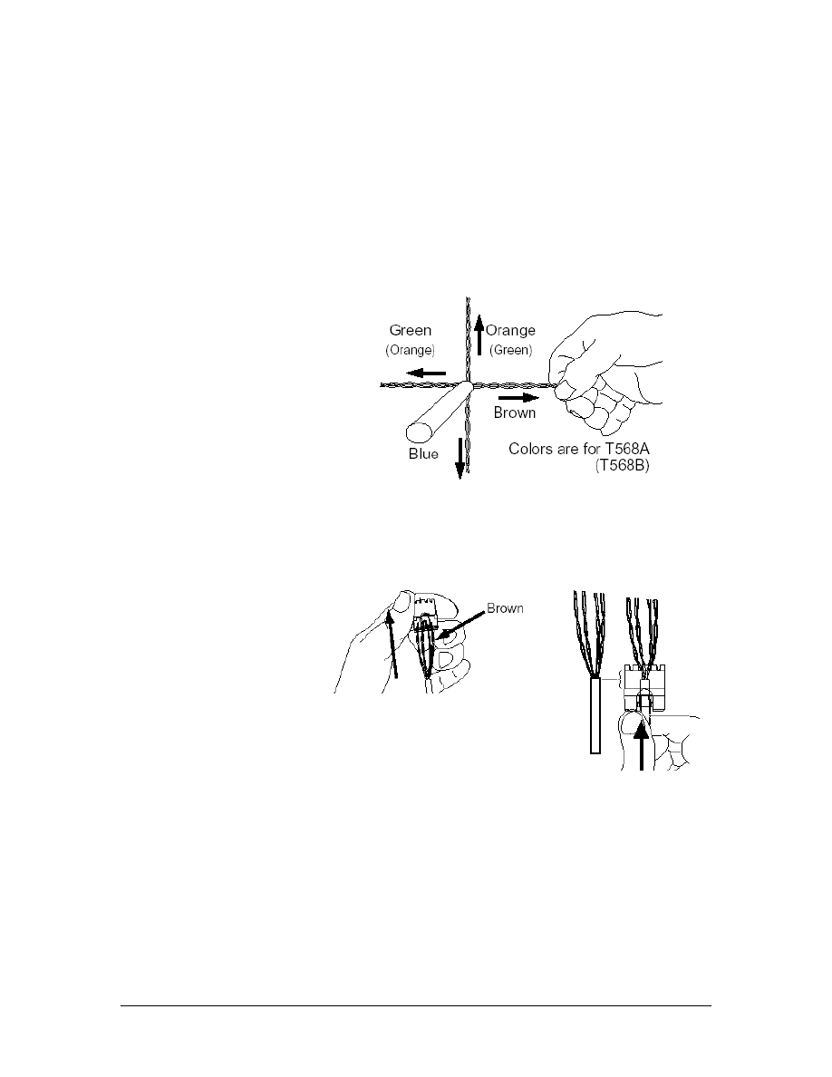
Step 2 Remove the Sheathing
Now that the cable is the proper length and has a unique label,
remove the sheathing without causing any damage to the conductors.
Use the copper strip tool to ring the cable about 5 cm (2 inches) from
the end of the cable. Should there be any exposed copper on the
conductors where the cable jacket was removed, cut off the end of the
cable and remove 5 cm (2 inches) of jacket again. If needed, repeat
the labeling process.
Step 3 Prepare the Cable and Jack
a. Separate the twisted pairs from each other without untwisting the
pairs. Pull the wires pairs to set their positions. Use the T568B
wiring standard when terminating this jack.
b. Gather the twisted pairs and insert
them into the cap.
Push the cable jacket until
the jacket end is located
under the label.
112 - 125 CCNA 1: Networking Basics v3.0 – Lab 5
Copyright
2003, Cisco Systems, Inc.
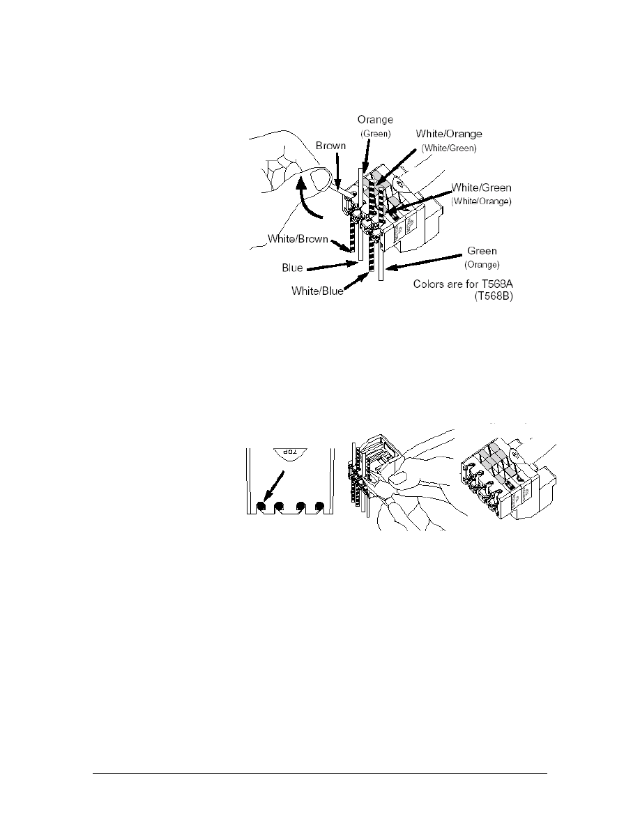
c. Untwist the pairs, one at a time starting with the outside pairs,
and place them into the correct slots. It is very important to
untwist each pair only as far as required to place the conductors
in the correct slots.
d. Trim each conductor flush with the cap with the wire snipping
tool. Be sure that all of the conductors are still seated in their
slots.
113 - 125 CCNA 1: Networking Basics v3.0 – Lab 5
Copyright
2003, Cisco Systems, Inc.
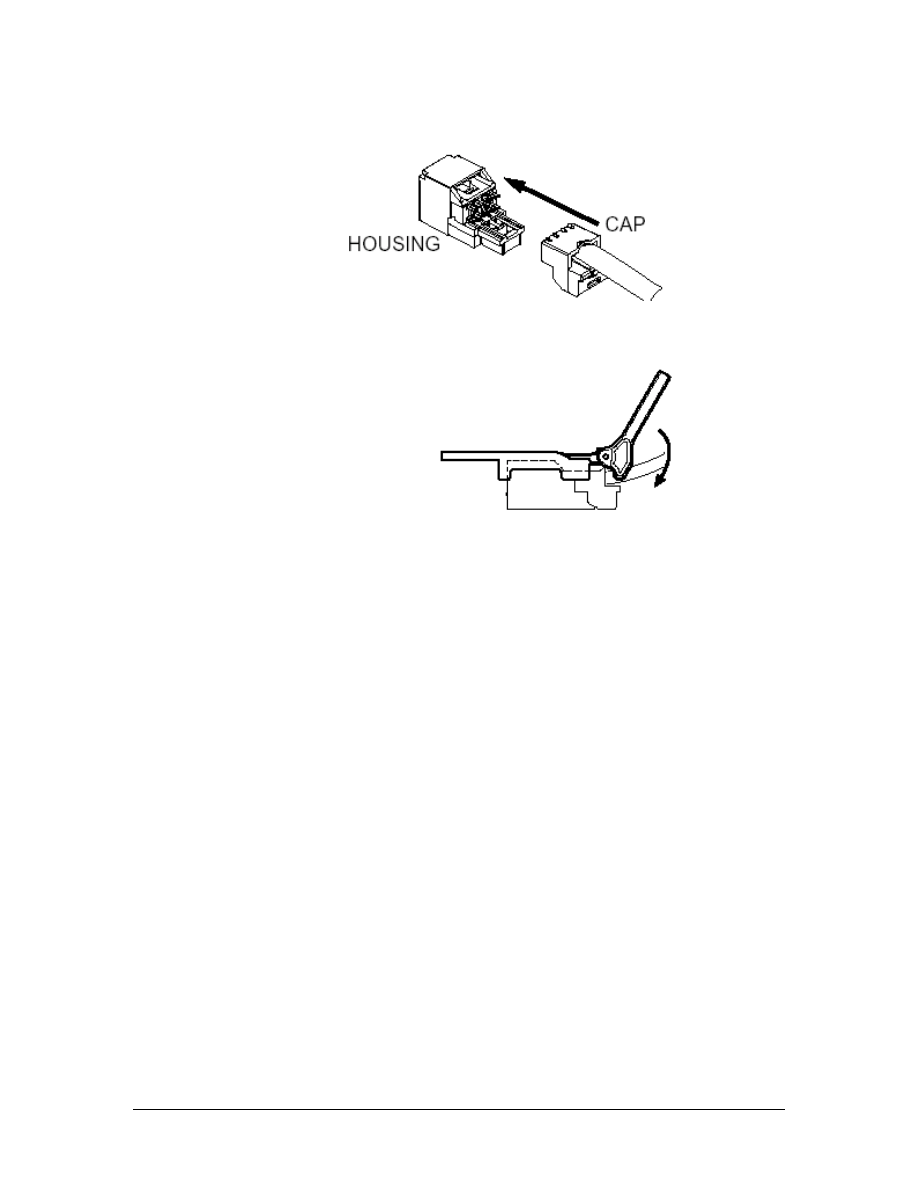
Step 4 Terminate the Cable
a. Slide the front of the Mini-Jack into the backing, making sure that
it is straight.
b. Use the Mini-Jack tool to press the two pieces together until they
snap. The cable has now been terminated. From behind the
panel, snap the jack module into a vacant position on the modular
patch panel.
Step 6 Terminate the Other End of the Cable
Install the other Mini-Jack module by using the T568B wiring
standard to terminate the cable and insert this jack into the correct
patch panel port.
Step 7 Testing
a. Use the Fluke 620 cable meter or LinkRunner to test the jack
installation.
b. What are the results of the test?
________________________________________________________
________________________________________________________
c. Are the results exactly the same when the second jack is tested?
________________________________________________________
d. Why or why not?
________________________________________________________
________________________________________________________
114 - 125 CCNA 1: Networking Basics v3.0 – Lab 5
Copyright
2003, Cisco Systems, Inc.

Step 8 Clean Up
Ensure that all tools are properly stored and remove all trash and
debris from the work area.
115 - 125 CCNA 1: Networking Basics v3.0 – Lab 5
Copyright
2003, Cisco Systems, Inc.

Lab 6: Category 6 Jack Termination
Objectives
• Practice proper safety procedures when using cabling tools.
• Terminate a Category 6 cable using proper techniques for
high-bandwidth data cabling.
Background/Preparation
Certain precautions must be followed when jacks terminate Category
6 cable. The tolerances of dimensions increase in importance as the
frequencies of voltages on the cables get higher and the data rates
increases.
The following instructions explain how to terminate Panduit MINI-
COM TX-6 PLUS Modules. Although installation techniques will
vary slightly, attention to these procedures will help students gain
facility with many Category 6 terminations and devices.
During this lab, each student on the team will terminate one end of a
Category 6 cable with an RJ-45 Mini-Jack jack and insert it into a
patch panel. Work in teams of 2 people. The following resources will
be required:
• 2 RJ-45 MINI-COM TX-6 PLUS Modules
• 60 cm (2 feet) of Category 6 UTP solid-core cable
• Safety glasses
• Wire stripper tool
• Permanent marker pen
• Mini-Jack module termination tool
• Wire snipping tool
• Electrician’s scissors
• Cable tester for verifying that the wires were connected
correctly
URL
Safety
Make sure to wear safety glasses or goggles during the entire lab.
116 - 125 CCNA 1: Networking Basics v3.0 – Lab 6
Copyright
2003, Cisco Systems, Inc.
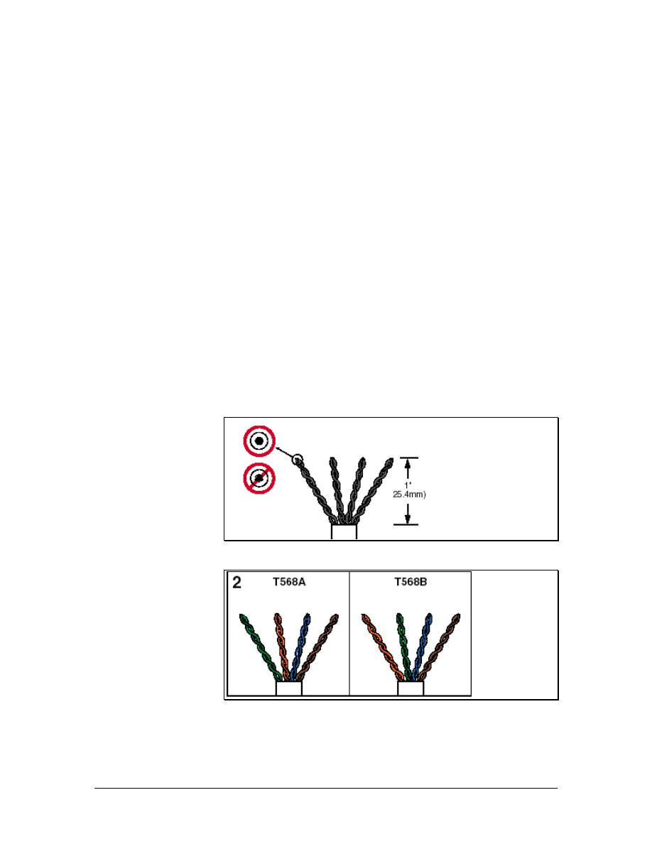
Step 1 Label the Cable
Place a label on the cable approximately 15 cm (6 inches) from the
end. Each cable must have a unique identifier. For this exercise, each
student should use a permanent marking pen to write their first name
on the end of the cable that they terminate. If the jack is to be inserted
into a patch panel, the name should be followed by pp1, for patch
panel 1, and the port number of the patch panel to which the student
will insert the jack.
Step 2 Remove the Sheathing and Order the Pairs
Now that the cable is the proper length and has a unique label,
remove the sheathing without causing any damage to the conductors.
Use the copper strip tool to ring the cable about 5 cm (2 inches) from
the end of the cable. Should there be any exposed copper on the
conductors where the cable jacket was removed, cut off the end of the
cable and remove 5 cm (2 inches) of jacket again. If needed, repeat
the labeling process.
Avoid damaging or disturbing the cable pairs any more than is
necessary. Fan out the cable pairs as shown in Figure 1, ordering the
colors as shown in Figure 2. Trim the pairs to length as shown in
Figure 1. Note that these instructions apply to solid, not stranded,
conductors.
Figure 1
Figure 2
117 - 125 CCNA 1: Networking Basics v3.0 – Lab 6
Copyright
2003, Cisco Systems, Inc.
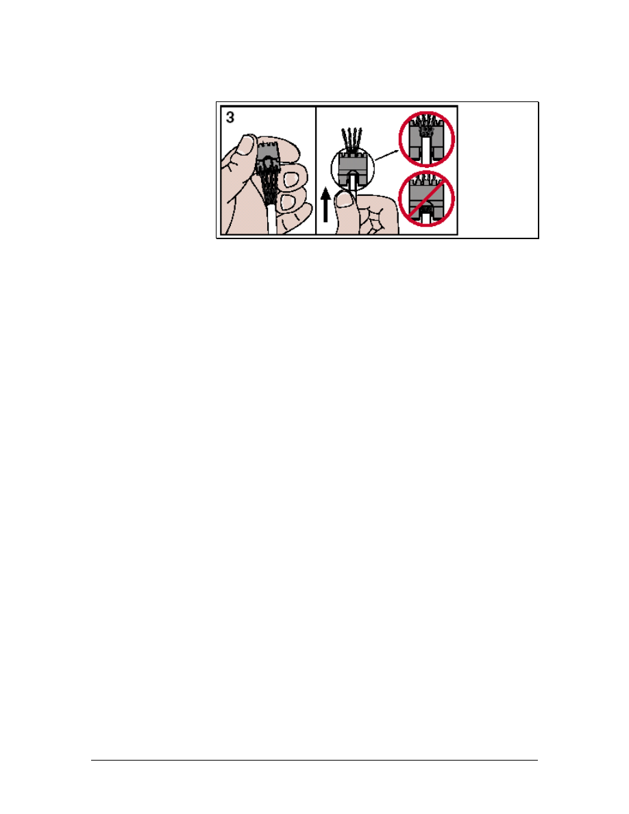
Step 3 Insert the Cable into the Jack
Figure 3
Holding the module assembly correct side up as shown, and with the
cable oriented as shown in the previous step, gently push the ordered
pairs through the holes in the module assembly. Insert the cable fully,
making sure that the pairs go through the correct holes.
118 - 125 CCNA 1: Networking Basics v3.0 – Lab 6
Copyright
2003, Cisco Systems, Inc.
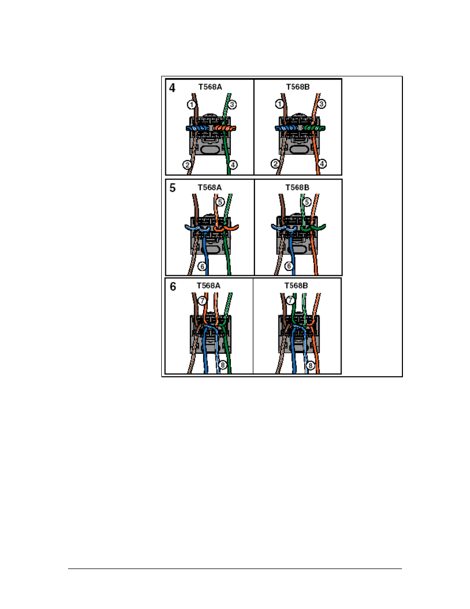
Step 4 Insert the Wires into the Notches
Figure 4
Using the figures as a guide, and twist the pairs in the order shown,
one at a time starting with the outside pairs, and place them into the
correct slots. It is very important to untwist each pair only as far as
required to place the conductors in the correct slots.
119 - 125 CCNA 1: Networking Basics v3.0 – Lab 6
Copyright
2003, Cisco Systems, Inc.
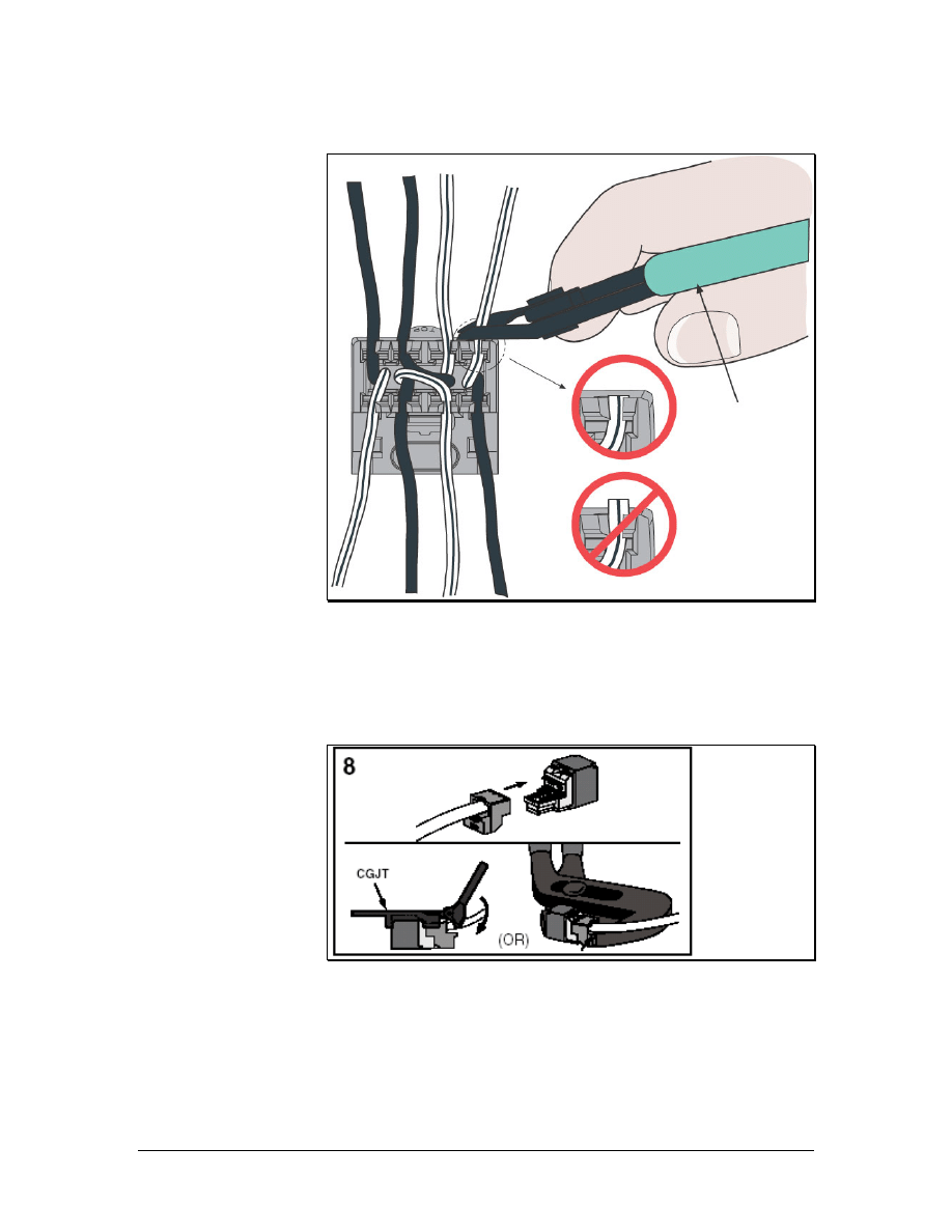
Step 5 Snip the Wire Ends Flush
Figure 5
Trim each conductor flush with the cap with the wire snipping tool.
Be sure that all of the conductors are still seated in their slots.
Step 6 Assemble the Module
Figure 6
a. Slide the front of the Mini-Jack into the backing, making sure that
it is straight.
b. Use the Mini-Jack tool to press the two pieces together until they
snap. The cable has now been terminated. Alternatively, use slip-
jaw pliers with the jaws set to the distance of the finished jack. If
120 - 125 CCNA 1: Networking Basics v3.0 – Lab 6
Copyright
2003, Cisco Systems, Inc.
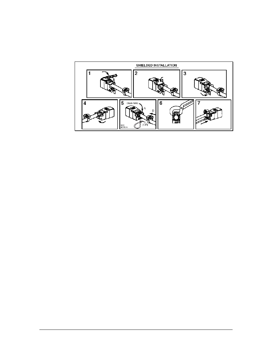
the pliers consistently damage the modules, try wrapping a little
electrical tape over each jaw before using.
Step 7 Shielded Cable Installation
Figure 7
For shielded cables, it will be necessary to install the metallic cover
as shown above. Route the drain wire to the rear of the module and
wrap it over the ground lug that extends to the rear of the cover.
Secure it with the plastic crimp ring as shown. If the module is to be
used in a surface mount fixture, use a nylon cable tie instead.
Step 8 Terminate the Other End of the Cable
Install the other Mini-Jack module by using the same wiring pattern,
T568A or T568B, to terminate the cable.
Step 9 Testing
Use the cable tester test the jack installation.
a. What are the results of the test?
____________________________________________________
____________________________________________________
b. Are the results exactly the same when the second jack is
tested?
____________________________________________________
c. Why or why not?
____________________________________________________
____________________________________________________
Step 8 Clean Up
Ensure that all tools are properly stored and remove all trash and
debris from the work area.
121 - 125 CCNA 1: Networking Basics v3.0 – Lab 6
Copyright
2003, Cisco Systems, Inc.

Lab 7: Terminating Category 5e to a 110-Block
Objectives
• Terminate Category 5e cable to a 110-type termination block.
• Properly use a 110 punch-down tool and 110-mulitpunch
tool.
Background/Preparation
The installer must be able to properly punch-down a 100-block. It is
important that each punch-down is executed correctly to ensure
proper connectivity.
A 110-block is a device used to terminate wires in a common place.
Wires from internal data networks and telephones are collected in the
block. Wires from outside the building are collected in a separate
block. These two blocks provide a way to connect the two collections
of wires in order to supply connectivity from external sources to the
desktop. This system of wire management keeps the wires organized
and allows for quick changes.
The instructor or lab assistant will designate the location of the
punch-down indicating the row 1-4 and position 1-6 on the block.
Work in teams of 1 to 4 people. The following resources will be
required:
• 110-punch block
• 1 m (3 feet) of Category 5e UTP cable
• C-4 Clips
• Copper strip tool
• Impact tool with 110 cutting blade
• 110-mulitpunch tool
• Pliers
URL
Safety
Safety glasses should be worn when using cutting tools. Use caution
when using impact tools because they have sharp blades.
122 - 125 CCNA 1: Networking Basics v3.0 – Lab 7
Copyright
2003, Cisco Systems, Inc.
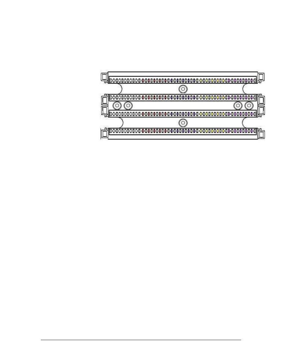
Step 1 Cable Preparation
a. Determine the position on the 110-block that will be used to
terminate the cable. Since a four-pair cable is being used,
positions are determined by counting four pairs from the left end
of the block. For example, position 1 would be the first four pairs,
position 2 would be the second four pairs, and so on. Label the
cable with respect to its position on the block. If the plan is to
terminate the cable on position 3, use the labeler and pen to
number the cable “#3”.
b. Now that the cable has a unique label, remove about 5 cm (2
inches) of sheathing without causing any damage to the
conductors.
Step 2 Fan the Conductors
a. Separate and fan out the conductor pairs without untwisting the
wires.
b. Place the wires one pair at a time into the termination points 7-10
cm (2-3 inches) from the end of the wires. This will place the two
wires in the correct position to be punched down while ensuring
that the twisting continues up to the point of termination. Use the
proper color-coding scheme, which is white/blue, white/orange,
white/green, and white/brown. Make sure that the tip colored
wire is placed to the left and the ring to the right.
Step 3 Punch Down
a. Place the single wire punch down tool over the wire that will be
punched. Be sure that the blade will only cut off the end of the
wire. The cutting edge of the blade should be facing the direction
to be cut.
123 - 125 CCNA 1: Networking Basics v3.0 – Lab 7
Copyright
2003, Cisco Systems, Inc.
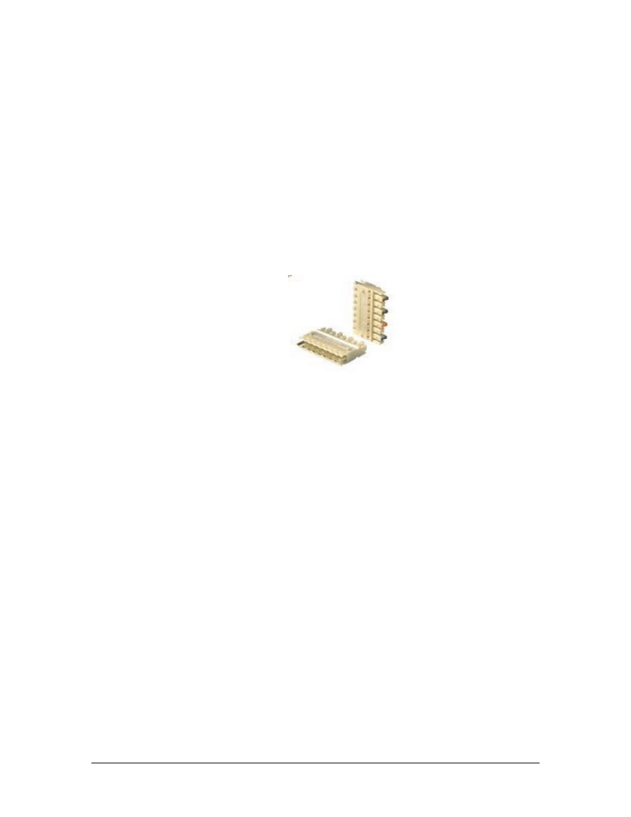
b. Press firmly on the impact tool until it clicks. This will ensure
that the wire has been punched down all the way and that the
excess wire has been cut. Do not hit the tool to punch down the
wires.
c. Repeat this step for the other wire. Gently remove the excess
wire.
Step 4 Punch Down the Rest of the Pairs
Repeat steps 2 and 3 for each pair of wires.
Step 5 The C-4 Connector
a. A C-4 connector is used for four-pair cables. The C-4 connector
is used to make the actual connection to the Category 5e cable.
Place the C-4 connector over the wires punched down, being sure
to match the color-coding correctly.
b. Position the 110-mulitpunch tool over the C-4 connector. The
multipunch tool is used to seat the C-4 connector.
c. Press firmly on the multipunch tool until it clicks. This will
ensure that the C-4 connector has been attached correctly and the
wire has been properly terminated.
Step 6 Inspection
a. Look carefully at the punched down cable.
b. Approximate the length of the wires that are untwisted?
________________________________________________________
c. What is the maximum allowable untwist length? _____________
d. How much of the pairs are exposed? _______________________
e. How many Category 5e cables can be terminated in a single row
of a 110-block? _______________________________________
124 - 125 CCNA 1: Networking Basics v3.0 – Lab 7
Copyright
2003, Cisco Systems, Inc.

Step 7 Clean Up
Remove the C-4 connector that was installed by using a pair of pliers
to grasp the clip and pulling it straight back until it pops off. Make
sure all tools are properly stored and that all trash and debris has been
removed from the work area.
125 - 125 CCNA 1: Networking Basics v3.0 – Lab 7
Copyright
2003, Cisco Systems, Inc.
Document Outline
- Structured Cabling Supplement
- Objectives
- 1 Structured Cabling Systems
- 2 Structured Cabling Standards and Codes
- 3 Safety
- 4 Tools of the Trade
- 5 Installation Process
- 6 Finish Phase
- 7 The Cabling Business
- Lab 1: Examination of Termination Types
- Lab 2: Terminating a Category 5e Cable on a Category 5e Patch Panel
- Lab 3: Tool Usage and Safety
- Lab 4: Identification of Cables
- Lab 5: Category 5e Jack Termination
- Lab 6: Category 6 Jack Termination
- Lab 7: Terminating Category 5e to a 110-Block
Wyszukiwarka
Podobne podstrony:
Molex Water Ingress In Structured Cabling Systems
Structures sp11
196 Capital structure Intro lecture 1id 18514 ppt
4 Plant Structure, Growth and Development, before ppt
Homework Data Structures
Lesley Jeffries Discovering language The structure of modern English
Photoshop CS photcs
ekloga 1, IBI AL - CŚ, interpretacje z literatury rzymskiej
Eurocode 5 EN 1995 1 1 Design Of Timber Structures Part 1 1 General Rules
ECCC Sylabus CS M2 A
Photoshop CS cwiczenia praktyczne
ECCC Sylabus CS M3 D
ECCC Sylabus CS M1 C
[38]QUERCETIN AND ITS DERIVATIVES CHEMICAL STRUCTURE AND BIOACTIVITY – A REVIEW
b11 pasmowa teoria cs a ZEKFBLQLCYFETXCFIIJOKSJ5FATJXVZFHFSAPPQ
Butterworth Finite element analysis of Structural Steelwork Beam to Column Bolted Connections (2)
Syntheses, structural and antimicrobial studies of a new N allylamide
więcej podobnych podstron