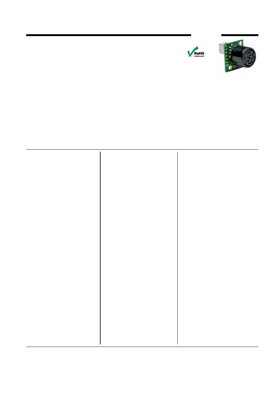
The MB1200 and MB1300 have a new high power output along with real-time auto calibration for changing
conditions (temperature, voltage or acoustic or electrical noise) that ensure you receive the most reliable (in
air) ranging data for every reading taken. The MB1200 and MB1300 low power 3.3V to 5V operation
provides very short to long-range detection and ranging, in a tiny and compact form factor. The MB1200 and
MB1300 detect objects from 0-cm* to 765-cm (25.1 feet) and provides sonar range information from 20-cm
out to765-cm with 1-cm resolution. Objects from 0-cm* to 20-cm typically range as 20-cm. (*Objects from 0-
mm to 1-mm may not be detected.) The interface output formats included are pulse width output (MB1200),
real-time analog voltage envelope (MB1300), analog voltage output, and serial digital output.
MB1200
MB1300
XL- MaxSonar
®
- EZ0™ (MB1200)
XL- MaxSonar
®
- AE0™ (MB1300)
Sonar Range Finder with High Power
Output, Noise Rejection, Auto Calibration &
Long-Range Wide Detection Zone
(Hardware gain of 4000)
Features
•
High acoustic power output
•
Real-time auto calibration
and noise rejection for every
ranging cycle
•
Calibrated beam angle
•
Continuously variable gain
•
Object detection as close as
1-mm from the sensor
•
3.3V to 5V supply with very
low
average
current
draw
•
Readings can occur up to
every 100mS, (10-Hz rate)
•
Free run operation can
continually measure and
output range information
•
Triggered operation provides
the range reading as desired
•
All interfaces are active
simultaneously
•
Serial, 0 to Vcc, 9600Baud, 81N
•
Analog, (Vcc/1024) / cm
•
Pulse Width (MB1200)
•
Real-time analog
envelope
(MB1300)
•
Sensor operates at 42KHz
Benefits
•
Acoustic and electrical noise
resistance
•
Reliable and stable range data
•
Sensor dead zone virtually
gone
•
Low cost
•
Quality controlled beam
characteristics
•
Very low power range finder
suited for multiple sensor or
battery based systems
•
Ranging can be triggered
externally or internally
•
Sensor reports the range
reading directly, frees up
user processor
•
Fast measurement cycle
•
User can choose any
of the sensor outputs
•
No calibration requirement is
perfect for when objects may
be directly in front of the
sensor during power up
•
Small size allows for easy
mounting
MaxBotix
®
Inc.
MaxBotix, MaxSonar, EZ0 & AE0 are trademarks of MaxBotix Inc.
XL-EZ0™ XL-AE0™ • v1.1b • 07/2009 • Copyright 2005 - 2011
Applications and Uses
•
UAV blimps, micro planes,
and some helicopters
•
Bin level measurement
•
Proximity zone detection
•
People detection
•
Robot ranging sensor
•
Autonomous navigation
•
Environments with acoustic
and electrical noise
•
Multi-sensor arrays
•
Distance measuring
•
Long range object
detection
•
Wide beam sensitivity
•
Users who prefer to process
the analog voltage
envelope (MB1300)
•
-40
°
C to +65
°
C operation
(+85
°
C limited operation)
approximately
actual size
Email:
info@maxbotix.com
Web:
www.maxbotix.com
Release: 01/31/11, pg. 1
Part Number: PI10335a
MB1200 & MB1300 Pin Out
GND
Return for the DC power supply. GND (& V+) must be ripple and
noise free for best operation.
V+
Operates on 3.3V - 5V. The average (and peak) current draw for 3.3V
operation is 2.1mA (50mA peak) and at 5V operation is 3.4mA (100mA
peak) respectively. Peak current is used during sonar pulse transmit.
Pin 5 -
(TX) When Pin 1 is open or held high, the Pin 5 output delivers
asynchronous serial with an RS232 format, except voltages are 0-Vcc.
The output is an ASCII capital “R”, followed by three ASCII character
digits representing the range in centimeters up to a maximum of 765,
followed by a carriage return (ASCII 13). The baud rate is 9600, 8 bits,
no parity, with one stop bit. Although the voltage of 0-Vcc is outside the
RS232 standard, most RS232 devices have sufficient margin to read 0-
Vcc serial data. If standard voltage level RS232 is desired, invert, and
connect an RS232 converter such as a MAX232.
When Pin 1 is held low, the Pin 5 output sends a single pulse, suitable for
low noise chaining (no serial data).
Pin 4 -
(RX) This pin is internally pulled high. The MB1200 &MB1300
will continually measure range and output if the pin is left unconnected
or held high. If held low the MB1200 &MB1300 will stop ranging.
Bring high 20uS or more for range reading.
Pin 3 -
(AN) This pin outputs analog voltage with a scaling factor of
(Vcc/1024) per cm. A supply of 5V yields ~4.9mV/cm., and 3.3V yields
~3.2mV/cm. Hardware limits the maximum reported range on this output
to ~700 cm at 5V and ~600 cm at 3.3V. The output is buffered and
corresponds to the most recent range data.
Pin 2 -
MB1200 (PW) This pin outputs a pulse width representation of
range. To calculate distance, use the scale factor of 58uS per cm.
MB1300 (AE) This pin outputs the analog voltage envelope of the
acoustic wave form.
Pin 1 -
Leave open (or high) for serial output on the Pin 5 output. When
Pin 1 is held low the Pin 5 output sends a pulse (instead of serial data),
suitable for low noise chaining.
MB1200 & MB1300 Circuit
175mS after power-up, the XL-MaxSonar
®
is ready to begin ranging. If Pin-4 is left open or held high (20uS or greater),
the sensor will take a range reading. The XL-MaxSonar
®
checks Pin-4 at the end of every cycle. Range data can be
acquired once every 99mS. Each 99mS period starts by Pin-4 being high or open, after which the XL-MaxSonar
®
calibrates
and calculates for 20.5mS, and after which, thirteen 42KHz waves are sent.
Then for the MB1200, the pulse width (PW) Pin-2 is set high. When an object is detected the PW pin is set low. If no
target is detected the PW pin will be held high for up to 44.4mS (i.e. 58uS * 765cm) (For the most accurate range data, use
the PW output of the MB1200 product.)
For the MB1300 with analog envelop output, Pin-2 will show the real-time signal return information of the analog
waveform.
For both parts, the remainder of the 99mS time (less 4.7mS) is spent adjusting the analog voltage to the correct level, (and
allowing the high acoustic power to dissipate). During the last 4.7mS, the serial data is sent.
MB1200 & MB1300 Real-time Auto Calibration
Each time after the XL-MaxSonar
®
takes a range reading it calibrates itself. The sensor then uses this data to range objects.
If the temperature, humidity, or applied voltage changes during sensor operation, the sensor will continue to function
normally. The sensor does not apply compensation for the speed of sound change versus temperature to any range
readings.
MB1200 & MB1300 Real-time Operation & Timing
MaxBotix
®
Inc.
MaxBotix, MaxSonar, EZ0 & AE0 are trademarks of MaxBotix Inc.
XL-EZ0™ XL-AE0™ • v1.1b • 07/2009 • Patents 7,679,996
MB1200
MB1300
Email:
info@maxbotix.com
Web:
www.maxbotix.com
Release: 01/31/11, pg. 2
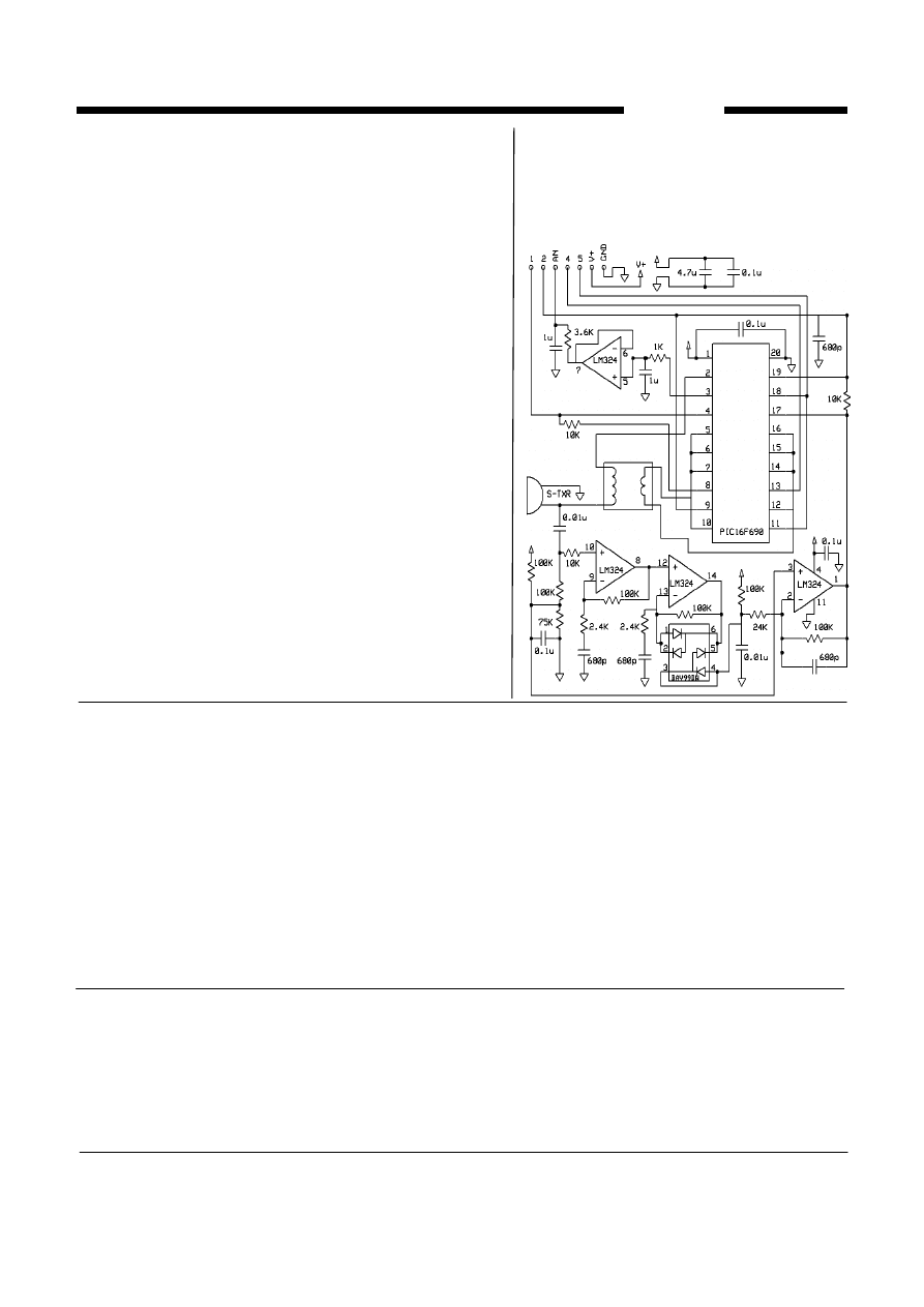
The sensor functions using active components
consisting of an LM324 and PIC16F690, together
with a variety of other components. The schematic
is shown to provide the user with detailed
connection information.
Part Number: PI10335a
J
U
T
P
K
S
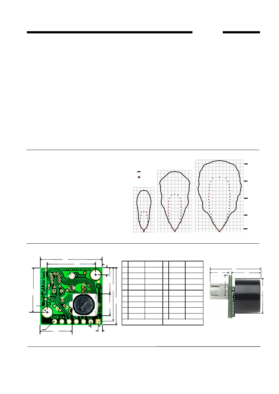
MB1200 & MB1300 Beam Characteristics
The MB1200 and MB1300 have a wide and long
sensitive beam that offers excellent detection of
objects and people. The MB1200 and MB1300
balances the detection of objects and people with
minimal side-lobes. Sample results for measured
beam patterns are shown to the right on a 30-cm
grid. The detection pattern is shown for dowels of
varying diameters that are place in front of the
sensor;
(A) 6.1-mm (0.25-inch) diameter dowel,
(B) 2.54-cm (1-inch) diameter dowel,
(C) 8.89-cm (3.5-inch) diameter dowel,
MaxBotix
®
Inc.
MaxBotix, MaxSonar, EZ0 & AE0 are trademarks of MaxBotix Inc.
XL-EZ0™ XL-AE0™ • v1.1b • 07/2009 • Copyright 2005 - 2011
MB1200
MB1300
A
B
C
3.3V
5V
150 cm
30 cm
sq.
300 cm
Beam characteristics are approximate
450 cm
(~5 ft)
(~10 ft)
(~15 ft)
(~1 ft)
600 cm
(~20 ft)
Email:
info@maxbotix.com
Web:
www.maxbotix.com
Release: 01/31/11, pg. 3
MB1200 & MB1300 Mechanical Dimensions
MB1200 & MB1300 Real-time Noise Rejection
While the XL-MaxSonar
®
is designed to operate in the presence of noise, best operation is obtained when noise
strength is low and desired signal strength is high. Hence, the user is encouraged to mount the sensor in such a
way that minimizes outside acoustic noise pickup. In addition, keep the DC power to the sensor free of noise.
This will let the sensor deal with noise issues outside of the users direct control (in general, the sensor will still
function well even if these things are ignored). Users are encouraged to test the sensor in their application to
verify usability.
For every ranging cycle, individual filtering for that specific cycle is applied. In general, noise from regularly
occurring periodic noise sources such as motors, fans, vibration, etc., will not falsely be detected as an object.
This holds true even if the periodic noise increases or decreases (such as might occur in engine throttling or an
increase/decrease of wind movement over the sensor). Even so, it is possible for sharp non-periodic noise
sources to cause false target detection. In addition, *(because of dynamic range and signal to noise physics,) as
the noise level increases, at first only small targets might be missed, but if noise increases to very high levels, it
is likely that even large targets will be missed.
*In high noise environments, if needed, use 5V power to keep acoustic signal power high. In addition, a high acoustic noise environment
may use some of the dynamic range of the sensor, so consider a part with less gain such as the MB1210/MB1310, MB1220/MB1320
MB1230/MB1330 or MB1240/MB1340. For applications with large targets, consider a part with ultra clutter rejection like the MB7092.
B
A
C
D
F
E
G
H
M
L
N
R
Q
V
A
0.785”
19.9mm
B
0.870”
22.1mm
C
0.100”
2.54mm
D
0.100”
2.54mm
E
0.670”
17.0mm
F
0.610
15.5mm
G
0.124”
dia.
3.1mm
dia.
H
0.100”
2.54mm
J
0.989”
25.11mm
K
0.645”
16.4 mm
values are nominal
L
0.735”
18.7mm
M 0.065”
1.7mm
N
0.038”
dia.
1.0mm
dia.
P
0.537”
13.64mm
Q
0.304”
7.72mm
R
0.351”
8.92mm
S
0.413”
10.5mm
T
0.063”
1.6mm
U
0.368”
9.36mm
V
0.492”
12.5mm
Weight, 5.9 grams
Part Number: PI10335a
MB1200
MB1300
MaxBotix
®
Inc.
Email:
info@maxbotix.com
Web:
www.maxbotix.com
MaxBotix, MaxSonar, EZ0 & AE0 are trademarks of MaxBotix Inc.
XL-EZ0™ XL-AE0™ • v1.1b • 07/2009 • Patents 7,679,996
Release: 01/31/11, pg. 4
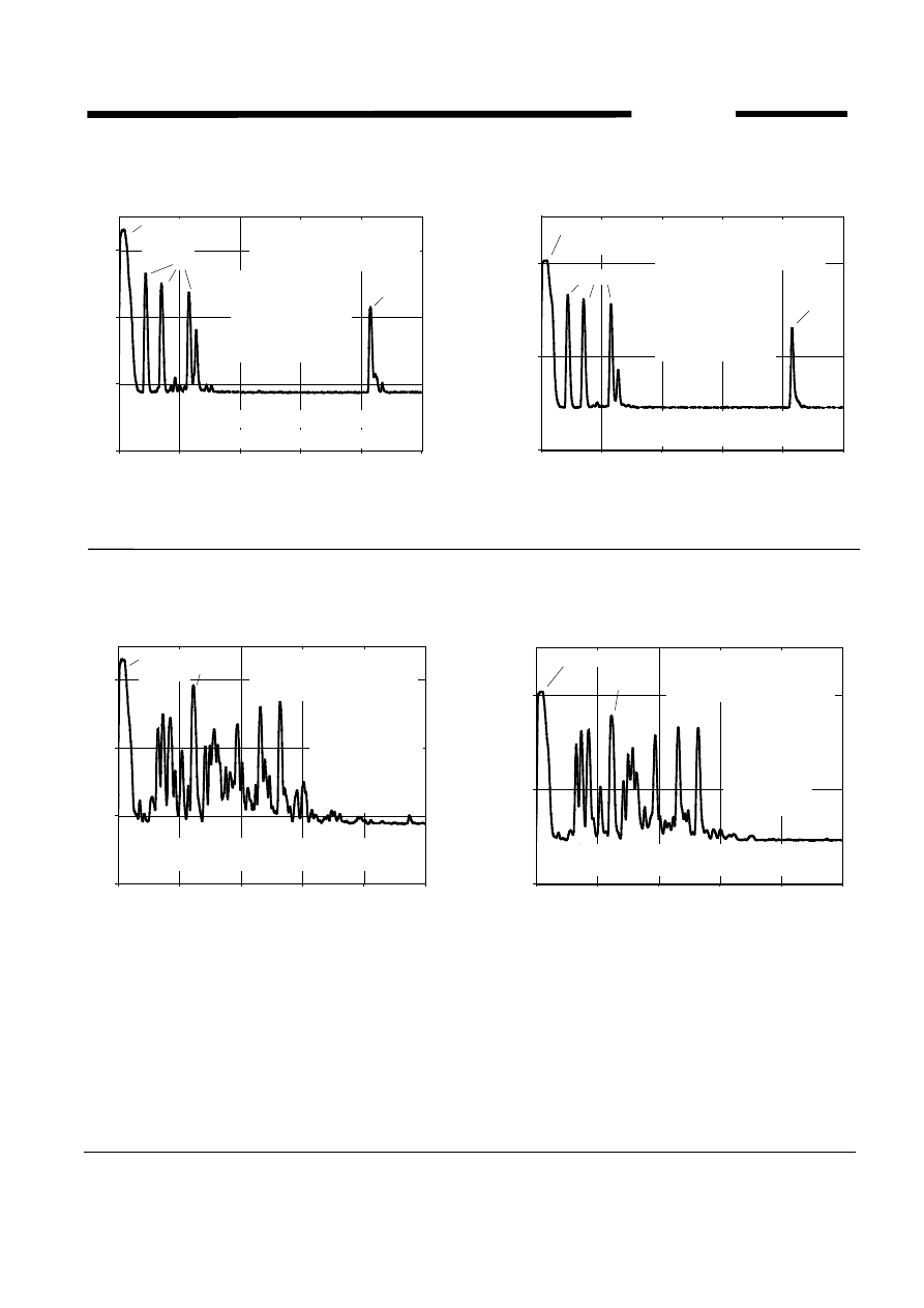
Typical Performance to Targets
Analog Envelope Output (Dowels, 5V)
0
1
2
3
0
10
20
30
40
50
10ms/DIV
A
N
A
L
O
G
E
N
V
E
L
O
P
E
(
V
)
Transmit
Burst
Targets
T
A
= 20
o
C, Vcc = 5V
Real-time on Pin 2 of MB1300
(or MB1200 internal)
Target
Conditions = acoustic test chamber
First target ranges at ~66cm.
Targets =
0.6cm dia. at 66cm,
2.5cm dia. at 111cm,
8.9cm dia. at 189cm,
and a 1m by 2m flat
panel at 704cm
Analog Envelope Output (Dowels, 3.3V)
0
1
2
0
10
20
30
40
50
10ms/DIV
A
N
A
L
O
G
E
N
V
E
L
O
P
E
(
V
)
Transmit
Burst
T
A
= 20
o
C, Vcc = 3.3V
Real-time on Pin 2 of MB1300
(or MB1200 internal)
Target
Targets =
0.6cm dia. at 66cm,
2.5cm dia. at 111cm,
8.9cm dia. at 189cm,
and a 1m by 2m flat
panel at 704cm
Conditions = acoustic test chamber
First target ranges at ~66cm.
Targets
Analog Envelope Output (Clutter, 5V)
0
1
2
3
0
10
20
30
40
50
10ms/DIV
A
N
A
L
O
G
E
N
V
E
L
O
P
E
(
V
)
Target
T
A
= 20
o
C, Vcc = 5V
Realtime on Pin 2 of MB1300
(or MB1200 internal)
Transmit
Burst
Target = 30cm sq.
at 2 meters
Conditions = 1.5
meter wide hallway
with cluttered sides
Object clutter from many objects at the sides of the
1.5 meter wide hallway. (Side clutter is detected.)
Clutter ranges
at ~100cm.
Analog Envelope Output (Clutter, 3.3V)
0
1
2
0
10
20
30
40
50
10ms/DIV
A
N
A
L
O
G
E
N
V
E
L
O
P
E
(
V
)
Transmit Burst
Target
T
A
= 20
o
C, Vcc = 3.3V
Realtime on Pin 2 of MB1300
(or MB1200 internal)
Clutter ranges
at ~100cm.
Target = 30cm sq.
at 2 meters
Conditions = 1.5
meter wide hallway
with cluttered sides
Object clutter from many objects at the sides of the
1.5 meter wide hallway. (Side clutter is detected.)
Typical Performance in Clutter
1200G0
1200G1
1200G2
1200G3
Part Number: PI10335a
Wyszukiwarka
Podobne podstrony:
05 czujniki polozenia przes lin Nieznany (2)
Czujnik cisnienia (barometr) na Nieznany
Czujnik polozenia wirnika BLDC Nieznany
407 B1DF04K1 Regulacja Czujnik polozenia walka rozrzadu Nieznany
407 B1HG01BAP0 Demontaz Montaz Czujnik wysokiego cisnienia paliwa Nieznany
pdf datasheet 5 id 352824 Nieznany
czujniki 2 id 129008 Nieznany
2008 03 Czujnik wilgociid 26450 Nieznany
pdf datasheet 3 id 352822 Nieznany
407 B1FD18K1 Sprawdzenie Cisnienie oleju (Bez czujnika cisnienia oleju ) Nieznany
datasheet BA5410 id 132063 Nieznany
MT6050i DataSheet id 310148 Nieznany
Czujniki dodatkowe Czujniki id Nieznany
Badanie czujnikow i przetwornik Nieznany
datasheet565 id 132064 Nieznany
BADANIE CZUJNIKOW TEMPERATURY i Nieznany (2)
Pojemnosciowy czujnik poziomu N Nieznany
więcej podobnych podstron