PIC and USB
-
French version/Version française
-
Forum: Microcontrollers and usb
Linux on Fujitsu stylistic 1200
How-to build a webserver for 30Euros with
A new autonomous robot project (V2)
How-to build a usb device a with 18F4550
Fabriquer un serveur web avec un circuit
Un petit robot autonome picbasic 3B
Un nouveau robot autonome à PIC
Construire un périphérique USB avec un PIC
Search:
Web
www.electronicfr.
com
USB and PIC tutorial
- Part 1 - How to build a USB device
with a PIC 18F4550 or 18F2550
-
Part 2 - Application: How to build
Part 1: How to
build a USB
device with a
PIC 18F4550 or
18F2550
Overview
PIC 18F4550 and 18F2550 are powerful microcontrollers including a full-speed USB V2.0 compliant interface.
With these MCU it's very easy for the hobbyist to design USB devices with very few components.
In this page, I will describe how to use the CDC firmware from Microchip. It permits to emulate a serial port
with a PC running Windows or Linux. It's also very easy to build HID devices.
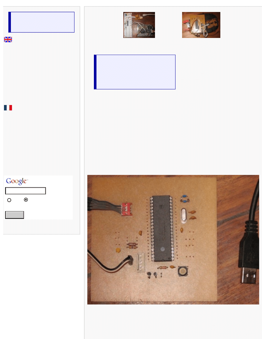
The 18F4550 experimentation board
Here is a picture of the experimentation board:
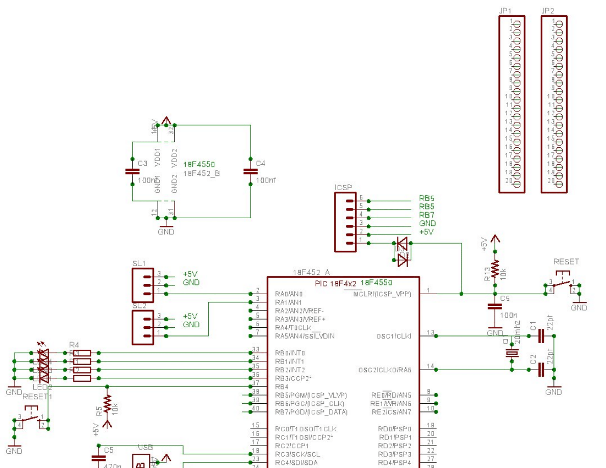
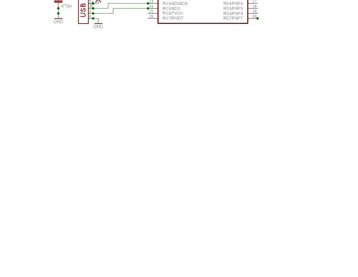
The following schematic is very simple, only few components are needed. It's a self powered USB device.
Please note I'm using the Olimex tiny-ICSD programmer, if you want to use another PIC ICSP programmer,
you should remove D1 and D2 and change the connector
Search
(You can click on the picture to get an high resolution picture)
This device is compatible with the microchip USB bootloader
Please note C5 is 470nF (the datasheet recommend 220nF but more is better) and should be low ESR (for
example a multi-layer ceramic). Don't forget the 100nF decoupling caps.
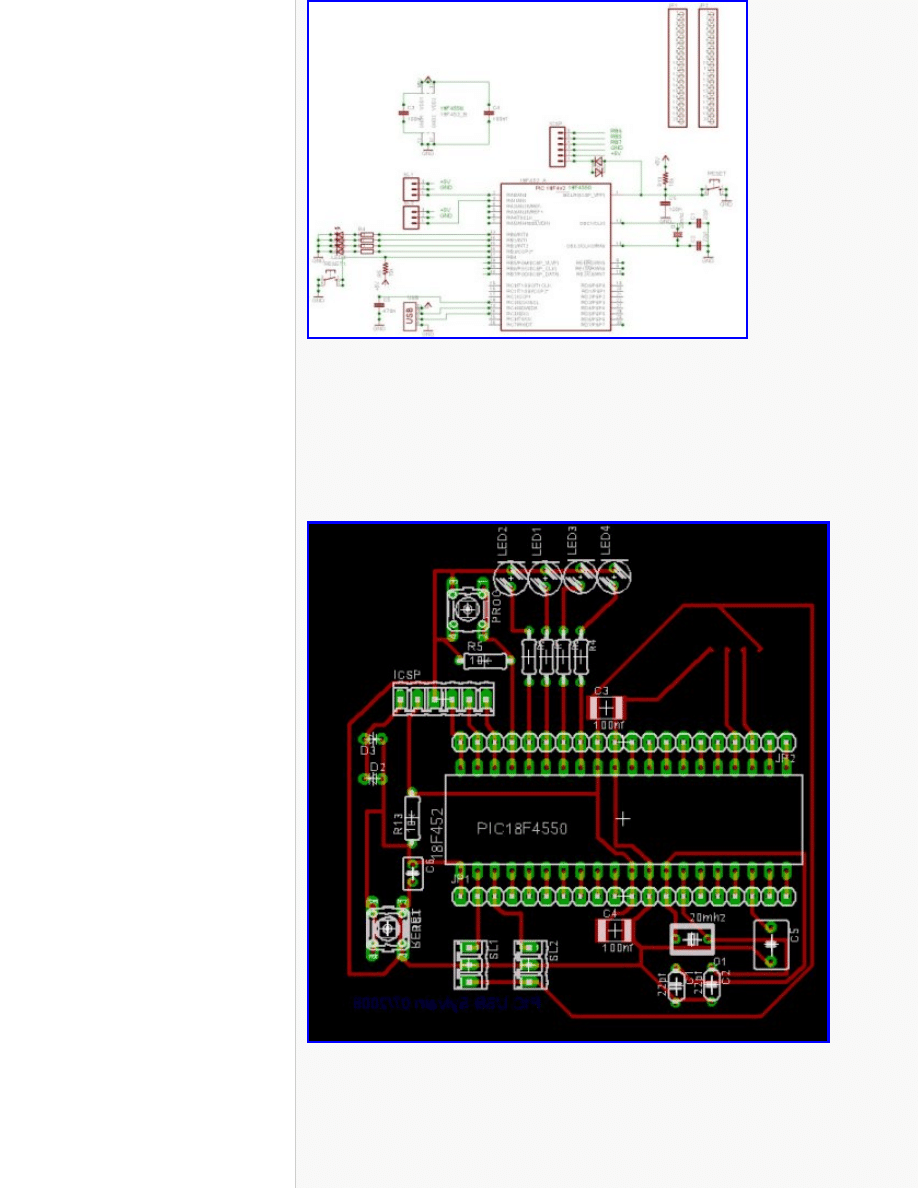
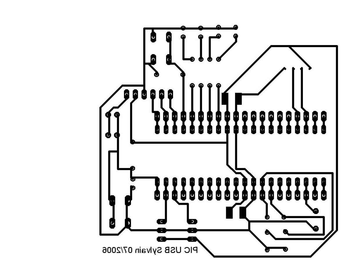
Here is a possible implementation
Click on the picture to get a 300dpi PCB
You can look at the wire's colour of your USB cable: Black=GND, Red=+5V, Green=Data+, White=Data-
The software

You can download
on the Microchip website. It's a windows .exe :(. The firmware we
will use is written in C (for the C18 Microchip compiler). This code is (royaltyes) free, but it's not a free
software, so it's not possible to redistribute modified source code
In this archive, you will find:
●
The USB bootloader and its source code in C18
●
A windows utility for the bootloader
●
The CDC firmware source code (serial emulation) in C18. It can be used
with the USB bootloader without modification
●
Another firmware for the HID device
●
A windows driver for CDC (under linux CDC-ACM is natively supported)
Some tips for your prototypes:
Source code is in the fw/cdc/MCHPUSB.mcw directory
You should comment the following lines in usbcfg.h for a self powered usb device:
#define USE_SELF_POWER_SENSE_IO
#define USE_USB_BUS_SENSE_IO
On my schematic, LED's are connected on port B. So you should modify io_cfg.h
#define mLED_1 LATBbits.LATB0
#define mLED_2 LATBbits.LATB1
#define mLED_3 LATBbits.LATB2
#define mLED_4 LATBbits.LATB3
You can put your own code on user.c. For example, look at Exercise_Example() in
user.c
.
Useful functions are getsUSBUSART() (get data) and putrsUSBUSART() (put data other the serial port)
Don't forget to check mUSBUSARTIsTxTrfReady() before to send data.
They are some examples in the exercise directory. For example, the following program (to put in
user.c
)
toggle the LED number 4 when you press the key "1" in the terminal
They are some examples in the exercice directory. For example, the following program (to put in
user.c
)
toggle the LED number 4 when you press the key "1" in the terminal
void Exercise_03(void){
if(getsUSBUSART(input_buffer,1))
{
if(input_buffer[0] == '1')
mLED_4_Toggle();
}
Under windows, you must install the provided driver and you can use the hyperterminal utility (19200bd
with a 20MHz crystal). Under linux, check the cdc-acm module, a new device /dev/ttyACM0 should appear.
If you don't want to use the bootloader, you must remove the
vector remapping
section in
main.c
and
change the linker script (look at important.readme.txt in the sources directory)


PIC and USB
-
French version/Version française
-
Forum: Microcontrollers and usb
·
Linux on Fujitsu stylistic 1200
·
How-to build a webserver for 30Euros with
·
·
A new autonomous robot project (V2)
·
How-to build an usb device with 18F4550 or
.
·
Fabriquer un serveur web avec un circuit
·
Un petit robot autonome picbasic 3B
·
Un nouveau robot autonome à PIC
·
Construire un périphérique USB avec un PIC
.
Search:
Web
www.electronicfr.
com
USB and PIC tutorial
-
Part 1 - How to build a USB device
- Part 2 - Application: How to build a
USB thermometer
Part 2: How to build a USB
thermometer with PIC
18F4550 or 18F2550
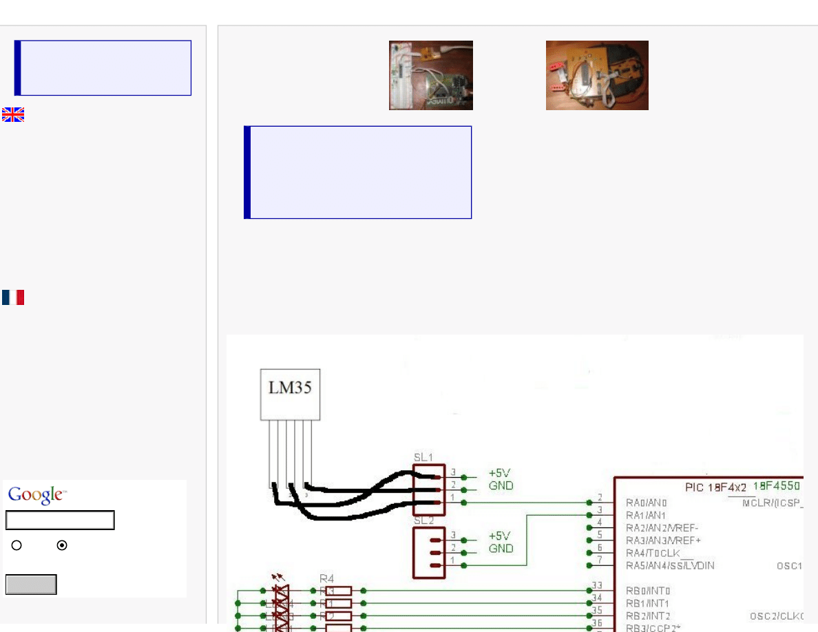
Sensor and schematic
We will add a temperature sensor to the circuit described in the first part of this tutorial. You can use the very usual LM35 circuit
), or many others circuits like MCP9701, TC1047...
The following schematic show how to plug the sensor on our USB experimentation board:
Search
The firmware
We will add some code for analog to digital convertion and temperature calculation in the file
user.x
//Lets add includes for ADC and strings manipulations
#include
#include
#include
//[...]
// We will write output data in this string
char input_buffer[64];
// [...]
void Exercise_Example(void)
{
int temp;
// [...]
else if(start_up_state == 3)
{
if(mUSBUSARTIsTxTrfReady())
{
//A0 set in input
TRISAbits.TRISA0 = 1;
memset(output_buffer, '\0', 64);
output_buffer[(6*5)] = '\r';
output_buffer[(6*5)+1] = '\n';
OpenADC(ADC_FOSC_8 & ADC_RIGHT_JUST & ADC_0_TAD,
ADC_CH0 & ADC_INT_OFF & ADC_VREFPLUS_VDD &
ADC_VREFMINUS_VSS,
0b1011);
SetChanADC(ADC_CH0);
Delay10TCYx( 50 );
ConvertADC(); // Start conversion
while( BusyADC() ); // Wait for ADC conversion
temp = ReadADC(); // Read result and put in temp
CloseADC(); // Disable A/D converter
temp=temp/7; //Convert in centigrad degrees
itoa(temp, output_buffer); // Convert to a
string
mUSBUSARTTxRam((byte*)output_buffer,(6*5)+2);
start_up_state=0;
}
}
}//end Exercise_Example
The value in Celsius degree will be sent threw the USB bus when the button on RB4 will be pressed.
Under windows, you can use the hyperterminal utility (19200bd with a 20MHz cristal) to see the value. Under linux you can use
cat /dev/
ttyACM0
.
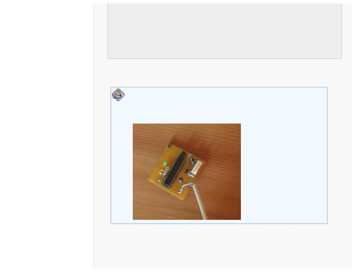
How to use a 18F2550
You can use the source code for 4550 with very few modifications. Just select the
appropriate device in the MPLAB configure menu. Change the linker script, and set the
configuration bits (like
). Remove any references to port D in io_cfg.h.
Here is a picture of a small prototype using PIC 18F2550:
Some links about USB
Making sense of the USB standard (Beyond logic)
Understanding USB (usbdeveloper)
USB 2.0 Specifications(usb.org)

Getting help
Ask your question to the electronicfr community
http://www.electronicfr.com/forum/phpBB2/viewforum.php?f=1
.
Disclaimer
ANY CONTENT ON THIS WEBSITE IS PROVIDED ``AS IS'' AND WITHOUT ANY EXPRESS OR IMPLIED WARRANTIES, INCLUDING, WITHOUT
LIMITATION, THE IMPLIED WARRANTIES OF MERCHANTIBILITY AND FITNESS FOR A PARTICULAR PURPOSE.
Next
Soon, you will find a schematic for a USB to serial (RS232) converter.
Document Outline
- electronicfr.com
Wyszukiwarka
Podobne podstrony:
How to build a USB device with PIC 18F4550 or 18F2550 (Website)
How to build a little autonomous robot with PIC 18F4520 (Website)
O'Reilly How To Build A FreeBSD STABLE Firewall With IPFILTER From The O'Reilly Anthology
O'Reilly How To Build A FreeBSD STABLE Firewall With IPFILTER From The O'Reilly Anthology
How to Build Solid State Electrical Over Unity Devices
Instructions how to repair USB flash failed devices
How to build a Raised Formal Pool
How to build a Retaining Wall
How to build an arbor id 206318 Nieznany
How to build a solar icemaker
Distillation How to build an Electric Still
HOW TO BUILD A DECK jak zbudowac taras
How To Build an Acid Alkaline Water Charger health healing search for [!B!]
How to Build a Walk Through Garden Pergola
więcej podobnych podstron