DRIVE AXLE, SPEED
REDUCER, AND
DIFFERENTIAL
E1.50-1.75XM
(E25-35XM, E25-35XM
2
) [D114];
E2.00XMS
(E40XMS, E40XM
2
S) [D114];
E1.50-2.00XM (E25-35Z, E40ZS) [E114]
PART NO. 897880
1400 SRM 618

SAFETY PRECAUTIONS
MAINTENANCE AND REPAIR
• When lifting parts or assemblies, make sure all slings, chains, or cables are correctly
fastened, and that the load being lifted is balanced. Make sure the crane, cables, and
chains have the capacity to support the weight of the load.
• Do not lift heavy parts by hand, use a lifting mechanism.
• Wear safety glasses.
• DISCONNECT THE BATTERY CONNECTOR before doing any maintenance or repair
on electric lift trucks. Disconnect the battery ground cable on internal combustion lift
trucks.
• Always use correct blocks to prevent the unit from rolling or falling. See HOW TO PUT
THE LIFT TRUCK ON BLOCKS in the Operating Manual or the Periodic Mainte-
nance section.
• Keep the unit clean and the working area clean and orderly.
• Use the correct tools for the job.
• Keep the tools clean and in good condition.
• Always use HYSTER APPROVED parts when making repairs. Replacement parts
must meet or exceed the specifications of the original equipment manufacturer.
• Make sure all nuts, bolts, snap rings, and other fastening devices are removed before
using force to remove parts.
• Always fasten a DO NOT OPERATE tag to the controls of the unit when making repairs,
or if the unit needs repairs.
• Be sure to follow the WARNING and CAUTION notes in the instructions.
• Gasoline, Liquid Petroleum Gas (LPG), Compressed Natural Gas (CNG), and Diesel fuel
are flammable. Be sure to follow the necessary safety precautions when handling these
fuels and when working on these fuel systems.
• Batteries generate flammable gas when they are being charged. Keep fire and sparks
away from the area. Make sure the area is well ventilated.
NOTE: The following symbols and words indicate safety information in this
manual:
WARNING
Indicates a condition that can cause immediate death or injury!
CAUTION
Indicates a condition that can cause property damage!

Drive Axle, Speed Reducer, and Differential
Table of Contents
TABLE OF CONTENTS
General ...............................................................................................................................................................
Description .........................................................................................................................................................
Drive Unit Assembly Repair .............................................................................................................................
Remove Complete Drive Unit Assembly as a Unit ......................................................................................
Traction Motor, Remove ................................................................................................................................
Drive Unit and Speed Reducer, Remove.......................................................................................................
Drive Axle, Disassemble................................................................................................................................
Differential and Speed Reducer, Disassemble .............................................................................................
Clean ..............................................................................................................................................................
Inspect ............................................................................................................................................................
Assembly of Drive Unit......................................................................................................................................
Find Correct Shim Set for Hypoid Gear .......................................................................................................
Pinion, Assemble and Install ........................................................................................................................
Differential and Ring Gear, Assemble and Install.......................................................................................
Input Gear for Speed Reducer, Assemble .....................................................................................................
Drive Axle and Hub Assembly, Assemble.....................................................................................................
Installation of Drive Unit ..................................................................................................................................
Drive Unit, Install .........................................................................................................................................
Traction Motor, Install...................................................................................................................................
Torque Specifications .........................................................................................................................................
Troubleshooting..................................................................................................................................................
This section is for the following models:
E1.50-1.75XM (E25-35XM, E25-35XM
2
) [D114];
E2.00XMS (E40XMS, E40XM
2
S) [D114];
E1.50-2.00XM (E25-35Z, E40ZS) [E114]
©2004 HYSTER COMPANY
i

"THE
QUALITY
KEEPERS"
HYSTER
APPROVED
PARTS

1400 SRM 618
Drive Unit Assembly Repair
General
This section has the description and repair proce-
dures for the differential, speed reducer, axle, and
the wheel bearings for the axle housing.
WARNING
The lift truck must be put on blocks for some
types of maintenance and repair. The removal
of the following assemblies will cause large
changes in the center of gravity: mast, drive
unit, battery, and the counterweight.
When
the lift truck is put on blocks, put additional
blocks in the following positions to maintain
stability:
a. Before removing the mast and drive unit,
put blocks under the counterweight so that
the lift truck cannot tip backward.
b. Before removing the battery and counter-
weight, put blocks under the mast assembly
so that the lift truck cannot tip forward.
The surface must be solid, even, and level when
the lift truck is put on blocks. Make sure that
any blocks used to support the lift truck are
solid, one-piece units.
Observe the previous warning before doing any re-
pairs.
Description
The drive unit is fastened to the frame of the lift
truck with trunnions and bolts. The outer ends of
the axle housings are the spindles for the wheel bear-
ings. The cups for the tapered roller bearings for the
wheel bearings are pressed into the hubs. The nut
on the end of the spindle holds the hub and adjusts
the preload on the wheel bearings. The axle shafts
are fastened to the hubs by capscrews and the studs
and nuts that fasten the wheels.
The drive axles have an oil seal between the inner
and outer bearings of the hub and a second oil seal
near the inner bearing.
The speed reducer and differential are parts of the
same assembly. See Figure 7. One speed reducer
gear is installed on the shaft of the traction motor.
A second speed reducer gear is fastened to the pinion
shaft for the differential.
Drive Unit Assembly Repair
REMOVE COMPLETE DRIVE UNIT
ASSEMBLY AS A UNIT
WARNING
The lift truck must be put on blocks for some
types of maintenance and repair. The removal
of the following assemblies will cause large
changes in the center of gravity: mast, drive
unit, battery, and the counterweight.
When
the lift truck is put on blocks, put additional
blocks in the following positions to maintain
stability:
a. Before removing the mast and drive unit,
put blocks under the counterweight so that
the lift truck cannot tip backward.
b. Before removing the battery and counter-
weight, put blocks under the mast assembly
so that the lift truck cannot tip forward.
The surface must be solid, even, and level when
the lift truck is put on blocks. Make sure that
any blocks used to support the lift truck are
solid, one-piece units.
NOTE: The drive unit assembly can be removed with
the traction motor as one unit. However, many ser-
vice technicians remove the traction motor before the
drive unit is removed. Motor removal reduces the to-
tal weight of the drive unit assembly. If another lift
truck is not available, remove the motor first. See
Traction Motor, Remove to remove the traction mo-
tor.
Use the following procedure to remove the complete
drive unit as one assembly using another lift truck:
1.
Operate the hydraulic pump and tilt the mast
fully backward. Put blocks under the bottom of
the outer channel of the mast. Tilt the mast for-
ward until the wheels just touch the floor. Put
1
Drive Unit Assembly Repair
1400 SRM 618
blocks under the frame and counterweight of the
lift truck and at the steer wheels to prevent truck
movement.
2.
Remove the battery as described in the Op-
erating Manual or the section Periodic
Maintenance 8000 SRM 552 for lift truck
models E1.50-1.75XM, E2.00XMS (E25-40XMS,
E25-40XM
2
S) (D114) and the section Periodic
Maintenance 8000 SRM 1060 for lift trucks
E1.50-2.00XM (E25-35Z, E40ZS) (E114).
Re-
move the floor plates and the access panel in the
bottom of the battery compartment.
3.
Remove the mast assembly as described in the
section Mast, Repairs 4000 SRM 522. Drain the
oil from the differential. Remove the floor plates.
4.
Disconnect the brake lines to the wheel cylinders.
Put caps on the open fittings and ports.
5.
Disconnect the parking brake cables at the lever
assembly as described in the section Brake Sys-
tem 1800 SRM 620. Remove the tilt hose clamps
from the speed reducer.
6.
Disconnect the power cables from the traction
motor.
Make an identification of which cable
is connected to each terminal. Disconnect the
wires to the brush wear indicator and the ther-
mal switch if installed.
7.
Carefully move the other lift truck forks under
the drive unit and install a block across the ends
of the forks as a support for the motor. Slowly
and carefully raise and tilt the forks to support
the drive unit.
8.
Make sure blocks are installed under the coun-
terweight to maintain stability. Remove the cap-
screws and washers that hold the drive unit as-
sembly to the trunnions. Remove the trunnion
caps.
9.
Disconnect the hydraulic line to the main con-
trol valve so that the motor mount can be discon-
nected. Put caps on the open hydraulic fittings
and ports. Remove the capscrews that fasten the
speed reducer mount at the frame. Disconnect
the motor mount.
10. On lift truck models E1.50-1.75XM, E2.00XMS
(E25-40XMS, E25-40XM
2
S) (D114), if there is a
seat brake, put a weight on the seat that will hold
the seat in the down position. Remove the nut,
capscrew, washers, and bushing at the pivot of
the brake linkage. Make a note of the arrange-
ment of the parts for correct assembly during in-
stallation. Disconnect the spring between the
linkage and the brake assembly.
NOTE: It can be necessary to raise the front of the
lift truck frame using a crane and chains as shown
in Figure 4.
11. Slowly and carefully move the drive unit assem-
bly out from under the lift truck. Use the lift
truck or a crane and slings to move the assem-
bly to a work area to make repairs.
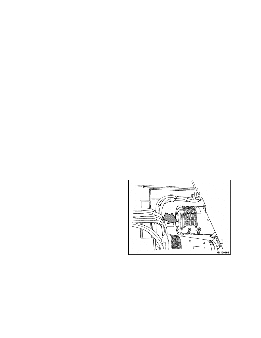
TRACTION MOTOR, REMOVE
This procedure describes the removal of the traction
motor through the battery compartment. See Fig-
ure 1. A lifting device can be fastened to the overhead
guard to lift the motor. If a crane will be used, re-
move the overhead guard for crane access. The steer-
ing pump and motor must be removed for clearance.
See the section Steering System for Electric Lift
Trucks 1600 SRM 485 for lift trucks E1.50-1.75XM,
E2.00XMS (E25-40XMS, E25-40XM
2
S) (D114) and
the section Steering System for AC Electric Lift
Trucks 1600 SRM 1054 for lift trucks E1.50-2.00XM
(E25-35Z, E40ZS) (E114) for removal.
NOTE:
TRACTION
MOTOR
SHOWN
IS
USED
ON E1.50-1.75XM, E2.00XMS (E25-40XMS, E25-
40XM
2
S) (D114) TRUCKS. TRACTION MOTOR USED
ON E1.50-2.00XM (E25-35Z, E40ZS) (E114) IS SIMI-
LAR.
Figure 1. Traction Motor
2
1400 SRM 618
Drive Unit Assembly Repair
NOTE: The traction motor can also be removed from
under the lift truck with the use of a floor jack, but
it is more difficult. If the traction motor is removed
from under the lift truck, the lift truck must be on
blocks with enough clearance for the jack and trac-
tion motor. Some lift trucks require removal of hy-
draulic lines to remove the traction motor from un-
der the lift truck.
1.
Remove the battery as described in the Op-
erating Manual or the section Periodic
Maintenance 8000 SRM 552 for lift truck
models E1.50-1.75XM, E2.00XMS (E25-40XMS,
E25-40XM
2
S) (D114) and the section Periodic
Maintenance 8000 SRM 1060 for lift trucks
E1.50-2.00XM (E25-35Z, E40ZS) (E114).
Re-
move the floor plates and the access panel in the
bottom of the battery compartment.
2.
On lift truck models E1.50-1.75XM, E2.00XMS
(E25-40XMS, E25-40XM
2
S) (D114), if there is a
seat brake, put a weight on the seat that will hold
the seat in the down position. Remove the nut,
capscrew, washers, and bushing at the pivot of
the brake linkage. Make a note of the arrange-
ment of the parts for correct assembly during in-
stallation. Disconnect the spring between the
linkage and the brake assembly.
3.
Disconnect the power cables from the traction
motor.
Make an identification of which cable
is connected to each terminal. Disconnect the
wires to the brush wear indicator and the ther-
mal switch if installed.
WARNING
The motor is heavy. Make sure that any lifting
device has enough capacity to lift the weight.
The motor can weigh approximately 90 to
140 kg (200 to 310 lb).
4.
Temporarily put the lift truck on blocks as
described in the section Periodic Mainte-
nance 8000 SRM 552 for lift truck mod-
els
E1.50-1.75XM,
E2.00XMS
(E25-40XMS,
E25-40XM
2
S) (D114) and the section Periodic
Maintenance 8000 SRM 1060 for lift trucks
E1.50-2.00XM (E25-35Z, E40ZS) (E114). Rais-
ing the lift truck will allow easier access to the
bottom bolts between the traction motor and the
speed reducer. Install a sling to hold the traction
motor. Use a wood block and a board under the
sling as shown in Figure 2 to control the traction
motor during removal. Use the crane to hold the
weight of the traction motor.
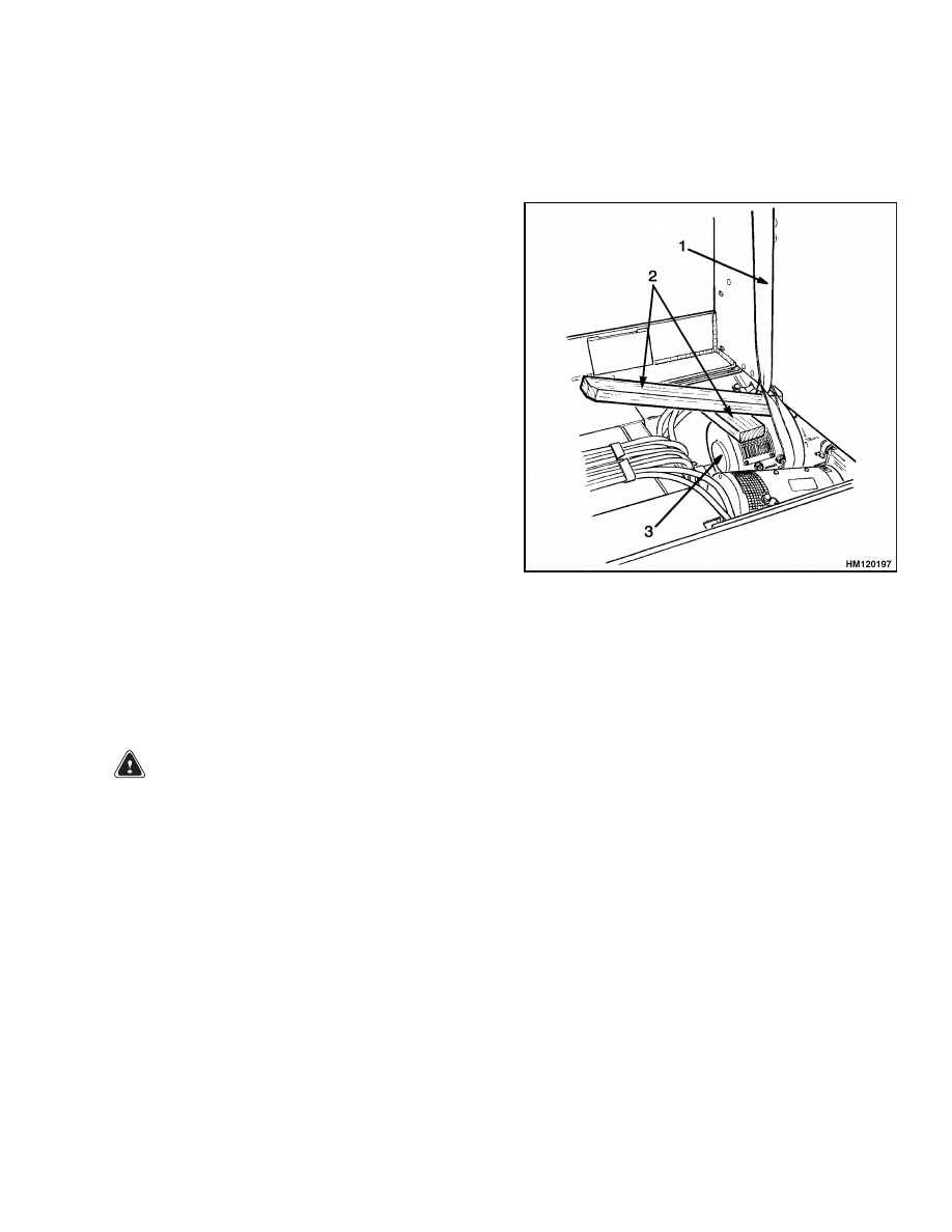
NOTE:
TRACTION
MOTOR
SHOWN
IS
USED
ON E1.50-1.75XM, E2.00XMS (E25-40XMS, E25-
40XM
2
S) (D114) TRUCKS. TRACTION MOTOR USED
ON E1.50-2.00XM (E25-35Z, E40ZS) (E114) IS SIMI-
LAR.
1.
SLING
2.
USE A WOOD BLOCK AND BOARD UNDER
SLING FOR A LEVER
3.
TRACTION MOTOR
Figure 2. Install Sling to Lift Traction Motor
5.
Disconnect the motor mount. Remove the bolts
between the speed reducer housing and the mo-
tor.
NOTE: The traction motors are in different config-
urations for different applications of the lift trucks.
Traction motors weigh approximately 90 to 140 kg
(200 to 310 lb). Make sure that the sling cannot slide
and permit the traction motor to fall.
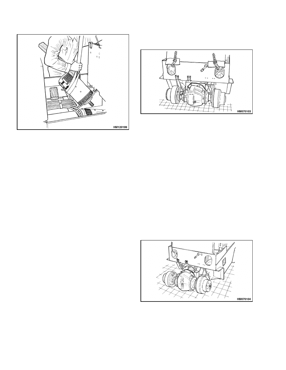
6.
Use the crane to move the traction motor to a
work space to make repairs as shown in Figure 3.
3
Drive Unit Assembly Repair
1400 SRM 618
NOTE:
TRACTION
MOTOR
SHOWN
IS
USED
ON E1.50-1.75XM, E2.00XMS (E25-40XMS, E25-
40XM
2
S) (D114) TRUCKS. TRACTION MOTOR USED
ON E1.50-2.00XM (E25-35Z, E40ZS) (E114) IS SIMI-
LAR.
Figure 3. Use Crane to Lift and Move Traction
Motor
DRIVE UNIT AND SPEED REDUCER,
REMOVE
The procedure in this section will describe removal
of the rest of the drive unit after the traction motor
has been removed.
1.
Remove the mast assembly as described in the
section Mast, Repairs 4000 SRM 522. Drain the
oil from the differential. Remove the floor plates.
2.
Disconnect the brake lines to the wheel cylinders.
Put caps on the open fittings and ports.
3.
Disconnect the parking brake cables at the lever
assembly. See the section Brake System 1800
SRM 620. Remove the tilt hose clamps from the
speed reducer.
4.
Disconnect the power cables from the traction
motor.
Make an identification of which cable
is connected to each terminal. Disconnect the
wires to the brush wear indicator and the ther-
mal switch if installed.
5.
Remove the drive wheels and lower the lift truck
so that the drive unit is on the floor. The crane
and chains must be the support for the front of
the frame. See Figure 4. The steer wheels sup-
port the rear of the lift truck.
NOTE: DRIVE UNIT IS DIFFERENT. PROCEDURE IS
THE SAME.
Figure 4. Lower Drive Unit to Floor
6.
Make sure blocks are installed under the coun-
terweight to maintain stability. Remove the cap-
screws and washers that hold the drive unit as-
sembly to the trunnion. Remove the trunnion
caps.
7.
Remove the capscrews that hold the speed re-
ducer housing to the mounts at the frame.
NOTE: It may be necessary to raise the front of the
lift truck frame using a crane and chains as shown
in Figure 4.
8.
Slowly and carefully move the drive unit assem-
bly out from under the lift truck. See Figure 5.
Use a lift truck or a crane and slings to move the
assembly to a work area to make repairs.
NOTE: DRIVE UNIT IS DIFFERENT. PROCEDURE IS
THE SAME.
Figure 5. Slide Drive Unit from Under Lift
Truck
4

1400 SRM 618
Drive Unit Assembly Repair
DRIVE AXLE, DISASSEMBLE
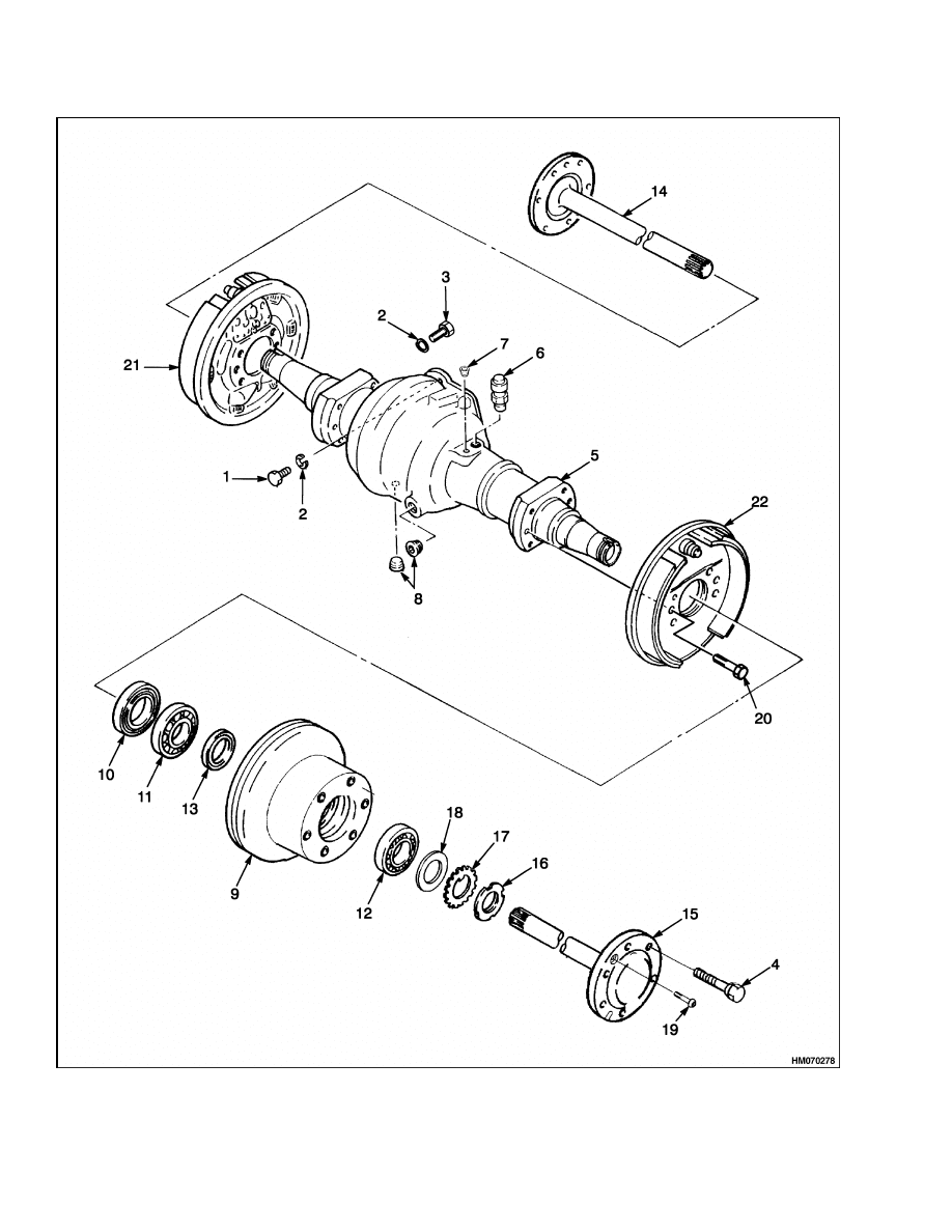
1.
Remove the two capscrews that fasten each axle
to the hub. See Figure 6. Remove the axles. If
the axles are difficult to remove from the hub,
hit the end of the axle flange with a hammer to
loosen the axle seal and splines. Do not use a pry
bar between the axle flange and the hub. Use of
a pry bar can damage the seal surface and cause
leaks.
2.
Install blocks under the axle housing as a sup-
port when the hubs are removed.
WARNING
The hub is heavy. Use care to prevent injury.
3.
Bend the lock plate so that the castle nut can be
removed from the axle spindle. Remove the nut,
lock plate, washer, and bearing. Carefully slide
the hub on the support surface to remove it from
the spindle. Hold the hub to keep the hub and
spindle aligned to prevent oil seal damage. Do
not permit oil or grease to get on the brake shoes.
4.
Remove the inner bearing and oil seals from the
spindle.
5.
If the brakes must be repaired, disassemble
the brake assembly as described in the section
Brake System 1800 SRM 620.
If necessary,
remove the brake assemblies. Remove the six
bolts that fasten each back plate to the axle.
Slide each brake assembly from the axle spindle.
6.
Use a sling and crane as a support for the speed
reducer. Remove the ten capscrews and washers
that hold the speed reducer to the axle and dif-
ferential housing. Remove the speed reducer and
differential assembly from the differential hous-
ing.
DIFFERENTIAL AND SPEED REDUCER,
DISASSEMBLE
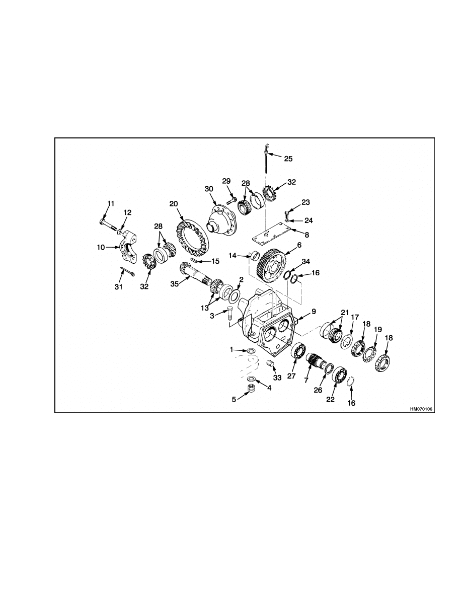
1.
Remove the six capscrews and washers that hold
the cover to the top of the speed reducer. See
Figure 7. Remove the cover.
2.
Disassemble only the parts of the speed reducer
and differential that must be repaired. If a new
ring gear and pinion are not to be installed, but
other new parts of the differential must be in-
stalled, check the contact pattern before disas-
sembly. The pattern and the gear clearance are
used as references for assembly. See Assembly of
Drive Unit in this section for the procedures.
3.
Remove the cotter pins from the adjustment
nuts.
Make marks on the parts so that they
will be assembled again in the same positions.
Remove the bearings, adjustment nuts, bearing
cups, and the differential assembly. Make sure
that you do not change the parts from the right
and left sides of the differential.
4.
Use a soft piece of metal (copper or aluminum)
to prevent the speed reducer gear from turning
when the nut is removed. Place the soft piece
of metal between the speed reducer gears or be-
tween the intermediate gear and the housing.
Remove the nuts and lockwasher from the pin-
ion shaft.
5.
Remove the washer with the key tab and the
bearing cup. Use a brass hammer to remove the
pinion from the speed reducer case. The speed
reducer gear and spacer will slide from the pin-
ion shaft as it is removed from the speed reducer
case. Make a note of the shim arrangement be-
tween the bearing and the spacer.
6.
Remove the speed reducer gear and spacer from
the housing.
7.
Remove the key from the pinion shaft. Use a
press to remove the bearing cone from the pinion.
8.
Use a press or a puller to remove the bearing cups
from the differential case.
9.
Remove the ring gear. Remove the twelve cap-
screws. Do not use a press or a hammer to re-
move the ring gear.
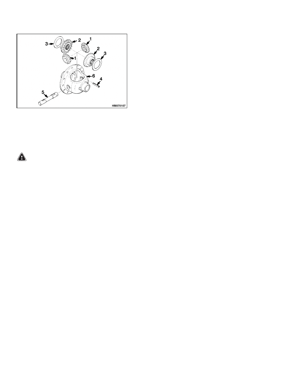
10. Disassemble the differential. Remove the shaft,
spider gears, and axle gears. See Figure 8.
11. Remove the retaining ring for the input gear to
the speed reducer. Remove the gear and bear-
ings. Use a puller to remove the inner bearing
from the speed reducer case.
5
Drive Unit Assembly Repair
1400 SRM 618
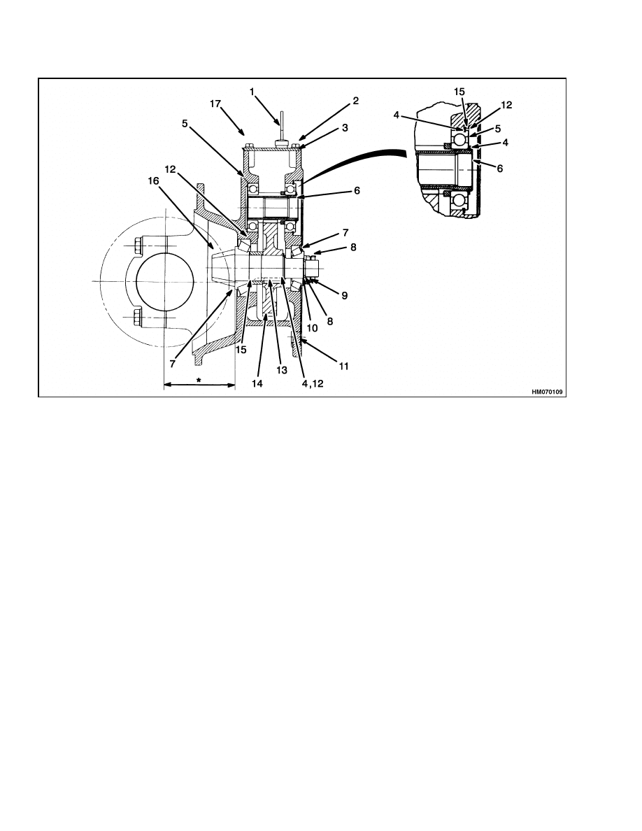
Figure 6. Drive Axle Assembly
6
1400 SRM 618
Drive Unit Assembly Repair
Legend for Figure 6
1.
CAPSCREW
2.
WASHER
3.
CAPSCREW
4.
BOLT
5.
HOUSING
6.
BREATHER PLUG
7.
PLUG
8.
PLUG
9.
HUB
10. OIL SEAL
11. BEARING
12. BEARING
13. OIL SEAL
14. RH AXLE SHAFT
15. LH AXLE SHAFT
16. LOCK NUT
17. LOCKWASHER
18. WASHER
19. CAPSCREW
20. BOLT
21. RH BRAKE ASSEMBLY
22. LH BRAKE ASSEMBLY
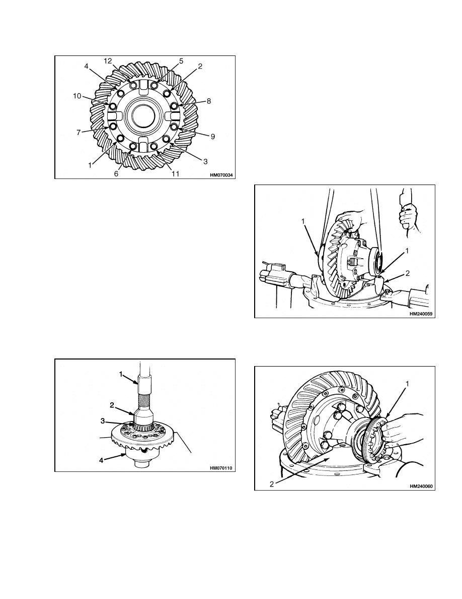
1.
SHIM
2.
SHIM
3.
CAPSCREW
4.
WASHER
5.
NUT
6.
INTERMEDIATE GEAR
7.
INPUT GEAR
8.
COVER
9.
HOUSING
10. CAP
11. CAPSCREW
12. WASHER
13. BEARING
14. SPACER
15. KEY
16. RETAINING RING
17. WASHER
18. NUT
19. LOCKWASHER
20. RING GEAR
21. BEARING
22. BALL BEARING
23. CAPSCREW
24. WASHER
25. DIPSTICK
26. SPACER
27. BALL BEARING
28. BEARING
29. BOLT
30. DIFFERENTIAL
31. COTTER PIN
32. ADJUSTMENT NUT
33. PLUG
34. SHIM
35. PINION
Figure 7. Speed Reducer and Differential Assembly
7
Assembly of Drive Unit
1400 SRM 618
1.
SPIDER GEAR
2.
AXLE GEAR
3.
THRUST WASHER
4.
PIN
5.
SHAFT
6.
CASE
Figure 8. Differential Assembly
CLEAN
WARNING
Always wear safety glasses.
Cleaning solvents may be flammable and toxic
and can cause severe skin irritation. When us-
ing cleaning solvents, always comply with the
solvent manufacturer’s recommended safety
precautions.
Compressed air can move particles so that they
cause injury to the user or to other personnel.
Make sure that the path of the compressed air
is away from all personnel.
Wear protective
goggles or a face shield to prevent injury to the
eyes.
Clean all the parts of the drive unit assembly with a
cleaning solvent. Dry the parts with compressed air.
INSPECT
Inspect all the parts of the drive unit assembly for
wear or damage. Normally all bearings are replaced
on an assembly that is disassembled. Always use
new seals during assembly. Make sure all surfaces
that take a sealant or gasket have been completely
cleaned and all sealant or gasket removed. Inspect
all machined surfaces for wear, scratches or other
damage.
1.
Check the pinion and ring gear for wear. Inspect
the spider gears and axle gears for worn teeth.
Inspect the shaft for wear where the gears turn.
The shaft and the holes for the shaft in the dif-
ferential case must fit tightly.
2.
Inspect the bearings and seals for defects.
3.
The splines for the axle shafts must not be dam-
aged.
Assembly of Drive Unit
FIND CORRECT SHIM SET FOR HYPOID
GEAR
NOTE: If the ring gear and pinion are worn or dam-
aged, a new set must be installed. The ring and pin-
ion must have the same reference numbers. When
the pinion bearings are replaced or the ring and pin-
ion are replaced, the shim arrangement must be ad-
justed for the new parts. Service technicians must of-
ten make more than one adjustment before the clear-
ances are correct. The installation procedures in Pin-
ion, Assemble and Install and Differential and Ring
Gear, Assemble and Install must also be done each
time the adjustment is changed. The adjustments
are correct when the gear clearance and contact pat-
tern between the ring and pinion are correct, and the
preload on the pinion bearings is correct.
The dimension on the end of the pinion is the varia-
tion from the standard Gauge Distance. The Gauge
Distance is the distance from the center of the ring
gear to the bearing shoulder behind the pinion gear.
Shims must be added between the bearing cup and
the housing for correct alignment of the pinion and
ring gear.
Look at the number on the pinion that was removed.
Subtract the variation number that is on the new pin-
ion. The remainder is the amount of shim thickness
that must be adjusted from the shim set on the pin-
ion that was removed. For examples, see Table 1. In
example 3, you can see that a negative number shows
that shims must be removed. Examples 1 and 2 and
4 show that shims must be subtracted from the orig-
inal shim set. Use this new shim set as a reference.
The final adjustment of the shim set is according to
the contact pattern on the ring gear teeth. See Ring
and Pinion Tooth Contact Adjustment.
8
1400 SRM 618
Assembly of Drive Unit
Table 1. Shims Adjustment for Pinion
Examples
1
2
3
4
If the numbers are given in inches:
Number on OLD GEAR
Number on NEW GEAR
+0.012
(+0.010)
+0.012
( 0.010)
+0.010
(+0.012)
0.010
( 0.012)
Shims to be Removed from Old Set
+0.002 in.
+0.022 in.
0.002 in.
(Add Shims)
+0.002 in.
If the numbers are given in millimeters:
Number on OLD GEAR
Number on NEW GEAR
+0.31
(+0.26)
+0.31
( 0.26)
+0.26
(+0.31)
0.26
( 0.31)
Shims to be Removed from Old Set
+0.05 mm
+0.57 mm
0.05 mm
(Add Shims)
+0.05 mm
PINION, ASSEMBLE AND INSTALL
NOTE: If the pinion and ring gear were not replaced,
install the original shim set. If a new ring gear and
pinion are being installed, first find the correct shim
set as described in Differential and Ring Gear, As-
semble and Install.
1.
Install the shims in the speed reducer housing for
the pinion shaft. If the bearing cups for the pin-
ion were removed, install them in the housing.
2.
Use a press to install the bearing cone on the pin-
ion. Put differential oil in the bearing and install
the spacer on the pinion shaft. See Figure 9.
3.
Install the correct shim set into the pinion gear
bore. Put the spacer and intermediate gear in the
housing. See Figure 10. Align the key slots for
the intermediate gear and pinion shaft. Install
the pinion in the housing and through the spacer
and speed reducer gear. Install the key in the key
slots.
4.
Install the other shim set on the pinion shaft
against the speed reducer gear.
The original
shim set can be used if both the pinion and
intermediate gear were not replaced.
Install
the retaining ring. The clearance between the
shim set and intermediate gear must be 0.1 mm
(0.004 in.)
maximum.
If necessary, remove
shims for the correct clearance.
5.
Put differential oil in the bearing and install the
bearing cone, the washer, and one lock nut. Do
NOT install the new lockwasher with the tab or
the other lock nut at this time.
1.
PRESS
2.
SLEEVE
3.
BEARING CONE
4.
PINION
Figure 9. Use Press to Install Pinion Parts
9
Assembly of Drive Unit
1400 SRM 618
1.
DIPSTICK
2.
COVER
3.
SPEED REDUCER HOUSING
4.
RETAINING RING
5.
BALL BEARING
6.
INPUT GEAR
7.
ROLLER BEARING
8.
LOCK NUT
9.
LOCKWASHER
10. WASHER
11. PLUG
12. SHIMS
13. KEY
14. INTERMEDIATE GEAR
15. SPACER
16. HYPOID GEAR SET (PINION
AND RING GEAR)
17. CAPSCREW
*THE GAUGE DISTANCE IS 122 mm (4.8 in.) PLUS OR MINUS THE VARIATION SHOWN ON THE END OF THE
PINION. THE ADJUSTMENT MUST BE WITHIN ±0.1 mm (±0.004 in.) OF THE ACTUAL DISTANCE.
Figure 10. Speed Reducer Assembly
6.
Use a soft piece of metal (copper or aluminium)
to prevent the speed reducer gear from turning
when the lock nut is tightened. Place the soft
piece of metal between the intermediate gear
and the housing. Tighten the lock nut, remove
the soft piece of metal, and check for a rotating
torque of 5.4 to 5.9 N•m (48 to 52 lbf in) at the
lock nut. Lightly hit the outside of the housing
to adjust the bearings in their seats. Do the se-
quence of this step until the measured rotating
torque is correct.
7.
Install the lockwasher and the other lock nut on
the pinion shaft. Tighten the lock nut. Do NOT
bend the lockwasher tab into the lock nut until
the correct clearance and backlash have been set.
Refer to Step 11 of Differential and Ring Gear,
Assemble and Install. Also refer to Find Correct
Shim Set for Hypoid Gear.
DIFFERENTIAL AND RING GEAR,
ASSEMBLE AND INSTALL
If the ring gear was removed from the differential
case, make sure the bolt holes are aligned and
install the ring gear on the differential case. Do
not use a press or a hammer to install the ring
gear. Apply Loctite
277 to the threads of the
bolts. Install the twelve capscrews. Tighten the
capscrews in a cross pattern to 152 to 167 N•m
(112 to 123 lbf ft). See Figure 11. Make sure the
ring gear is in the correct position against the
flange of the differential case.
10
1400 SRM 618
Assembly of Drive Unit
Figure 11. Tighten Hex Head Screws in Cross
Pattern
2.
Lubricate and install the axle gears and thrust
washers in the differential case as shown in Fig-
ure 8.
3.
Install the spider gears and shaft in the differen-
tial case. Install the roll pin that holds the shaft
in the differential case as shown in Figure 8.
4.
Install the bearing cones on the differential case.
See Figure 12.
5.
Apply axle lubricant on the inner diameter of the
bearing cups and on both bearing cones that are
installed on the differential. Do not permit lubri-
cant on the outer diameter of the bearing cups or
the bearing bores of the housing.
1.
PRESS
2.
SLEEVE
3.
BEARING CONE
4.
DIFFERENTIAL
CASE
Figure 12. Bearing Cones Installation
6.
Install the differential assembly into the hous-
ing. See Figure 13. The bearing cups must fit
correctly into the bores of the housing.
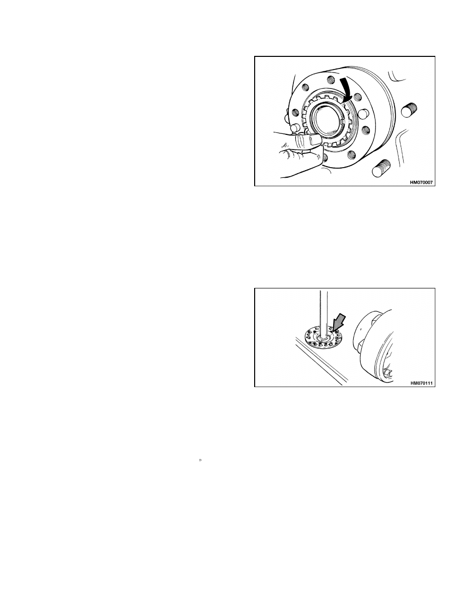
7.
Install the two bearing adjustment nuts into
position in the housing bores. See Figure 14.
Use your hand to tighten each adjustment nut
against the bearing cup.
8.
Align the marks on the bearing caps with the
marks on the housing. See Figure 15 and Fig-
ure 16. Apply Loctite
®
to the threads, and install
and tighten the bolts for the bearing caps to 263
to 315 N•m (194 to 233 lbf ft).
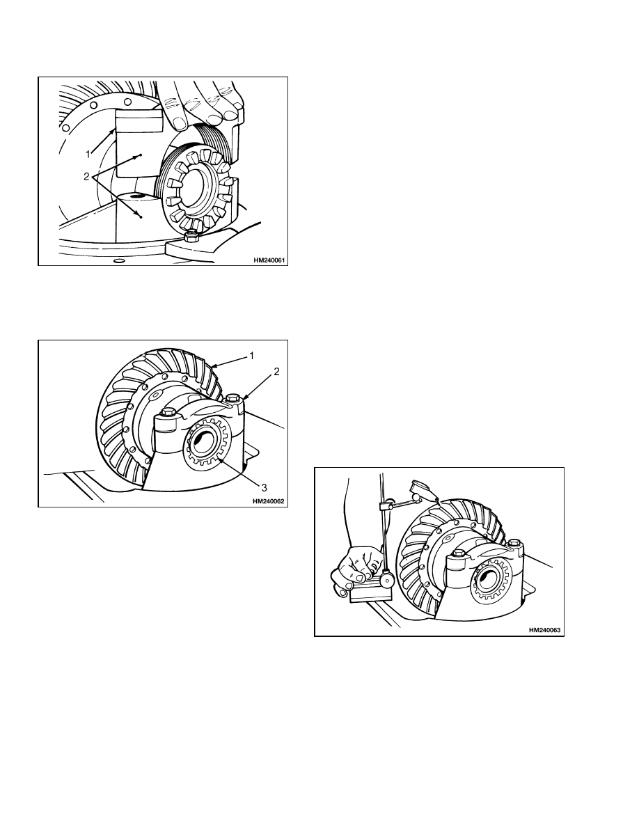
1.
BEARING CUP
2.
HOUSING
Figure 13. Differential Assembly Installation
into Housing
1.
ADJUSTMENT NUT
2.
HOUSING
Figure 14. Adjustment Nuts Installation
11
Assembly of Drive Unit
1400 SRM 618
1.
BEARING CAP
2.
ALIGNMENT
MARKS
Figure 15. Bearing Caps Installation
1.
RING GEAR
2.
BEARING CAP
3.
ADJUSTMENT NUT
Figure 16. Bearings Caps and Adjustment Nuts
Installation
9.
Tighten the adjustment nuts to remove the clear-
ance between the adjustment nuts and the bear-
ings. Make sure there is clearance between the
ring gear and pinion.
Loosen the adjustment
nut only until there is zero clearance between
the bearings and the adjustment nuts. Tighten
each adjustment nut two notches more than zero
clearance to put a preload on the bearings.
10. Check the clearance between the ring gear and
pinion. The ring gear and pinion must have a
clearance of 0.15 to 0.2 mm (0.006 to 0.008 in.).
See Figure 17. Use the adjustment nuts to move
the ring gear toward the pinion to decrease the
clearance. Move the ring gear away from the
pinion to increase the clearance. Loosen one ad-
justment nut the same amount as the other ad-
justment nut is tightened to adjust the clearance
between the ring gear and pinion.
When the
clearance is correct, tighten the capscrews for the
bearing caps to 263 to 315 N•m (194 to 233 lbf ft).
11. Check the pattern on the teeth of the ring gear.
Apply an indicator color (Prussian Blue or Yel-
low) or grease to the teeth. Use a pry bar between
the edge of the ring gear and the housing to keep
the ring gear from turning freely. Turn the pin-
ion shaft. Compare the pattern on the ring gear
teeth with the patterns shown in Ring and Pin-
ion Tooth Contact Adjustment. Adjust the gear
clearances as necessary. As shown in the adjust-
ment procedures above, the pinion can also need
adjustment. Refer to Find Correct Shim Set for
Hypoid Gear and Pinion, Assemble and Install to
adjust the pinion. An adjustment of the pinion to
move the contact pattern also normally requires
an adjustment of the ring gear clearance as de-
scribed in Step 10.
12. After the adjustments and wear pattern are cor-
rect, install the cotter pins to lock the adjustment
nuts.
Figure 17. Clearance Check Between Ring
Gear and Pinion
12
1400 SRM 618
Assembly of Drive Unit
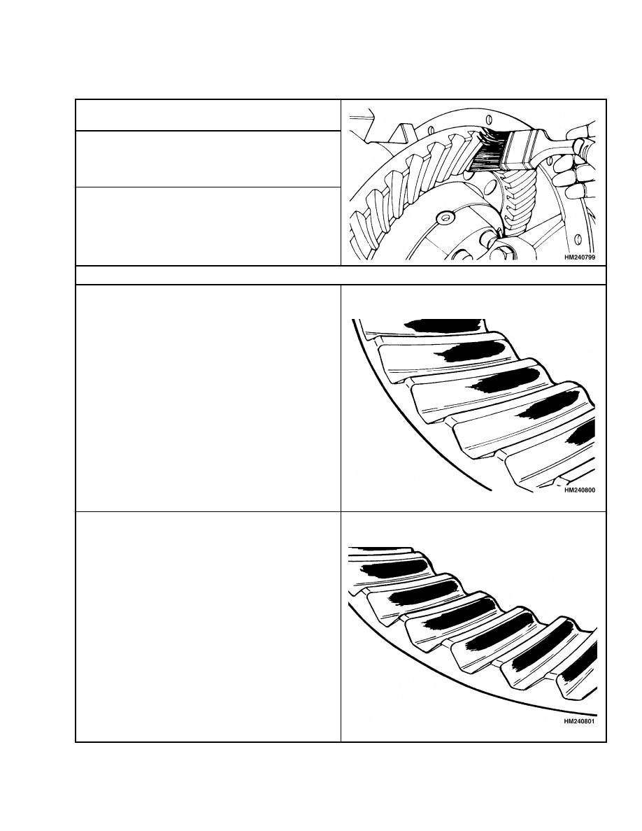
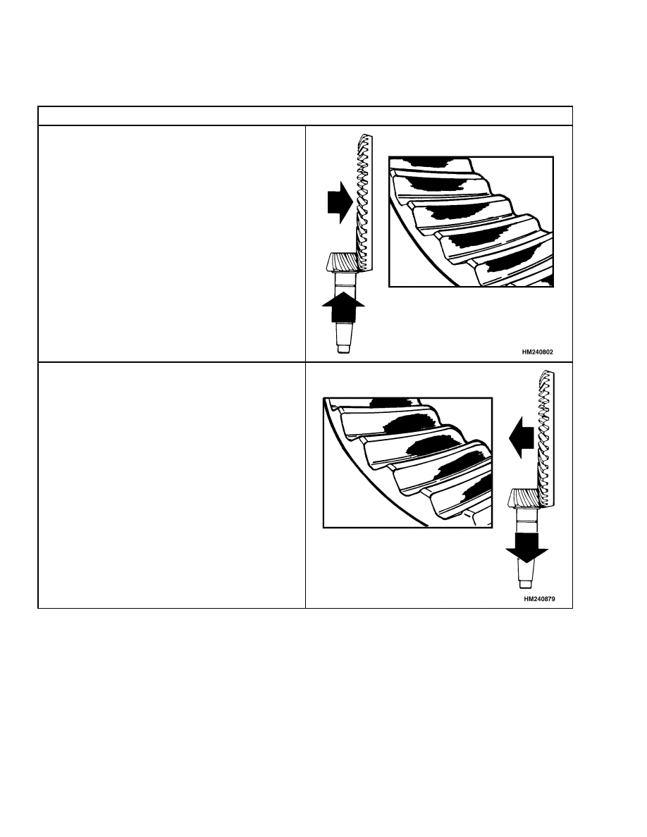
Table 2. Ring and Pinion Tooth Contact Adjustment
1.
Apply a colored dye or grease to approximately 12
of the ring gear teeth.
2.
Rotate ring gear forward and backward so that
the 12 gear teeth go past the drive six times to
get to the contact patterns. Repeat if needed to
get a clearer pattern.
3.
Check the tooth contact pattern on the ring gear.
Make sure that the pattern is checked on the side
of the tooth where the pinion applies the force.
Correct Tooth Contact
The contact area is the center between the top and
bottom of the tooth. The contact area is toward the
inner circumference of the ring gear.
NOTE: Normal pattern during adjustment shown.
The contact area is the center between the top and
the bottom of the tooth. The contact area will be
almost the full length of the tooth.
NOTE: Wear pattern from operation shown.
13
Assembly of Drive Unit
1400 SRM 618
Table 2. Ring and Pinion Tooth Contact Adjustment (Continued)
Incorrect Tooth Contact
The pinion is too far away from the center of the
gear. Add shims to move pinion toward ring gear.
Check that the clearance is correct. Some movement
of ring gear away from pinion may be necessary.
The pinion is too close to the center of the ring gear.
Remove shims to move pinion away from the ring
gear. Check that the clearance is correct. Some
movement of the ring gear toward the pinion may
be necessary.
INPUT GEAR FOR SPEED REDUCER,
ASSEMBLE
1.
Install the ball bearing in the end of the bore in
the speed reducer case. Install the spacer, the
other ball bearing, and the retainer on the input
gear. Install the input gear assembly into the
speed reducer case. Install the retaining ring to
fasten the bearing in the housing.
2.
Measure the clearance between the bearing and
the retainer on the input gear. There must be 0
to 0.1 mm (0 to 0.004 in.) clearance. If neces-
sary, remove the retainer and add enough shims
so that the clearance is no more than 0.1 mm
(0.004 in.). Install the retainer.
3.
Make sure the cover of the speed reducer is clean
without any old sealant on the cover or housing.
Use new sealant and install the cover using the
14
1400 SRM 618
Assembly of Drive Unit
six capscrews and washers. Tighten the cover
capscrews to 21 to 25 N•m (15 to 18 lbf ft).
4.
If the traction motor will be installed as part of
the drive unit assembly, it can be installed now.
Install traction motor as described in Traction
Motor, Install.
DRIVE AXLE AND HUB ASSEMBLY,
ASSEMBLE
1.
Make sure the axle housing and differential as-
sembly are clean with no old sealant. Apply liq-
uid sealant to the axle housing, and install the
differential assembly and speed reducer into the
axle housing. The two M10 × 1.5 × 30 bolts go
into the top holes that fasten the housings to-
gether. Install the other six M10 × 1.5 × 35 bolts
to fasten the two housings together. Tighten the
bolts to 41 to 49 N•m (30 to 37 lbf ft).
2.
Lubricate the axle spindles with differential oil
and slide the brake assembly on to the axle spin-
dles. Install the bolts that hold the brake assem-
bly. Tighten the bolts to 152 to 167 N•m (112 to
123 lbf ft).
NOTE: The outer wheel bearing is lubricated by gear
oil from the axle housing. The inner wheel bearing
is lubricated by wheel bearing grease. Do not use too
much grease to lubricate the inner wheel bearing so
that grease is pushed past the seal into the area for
the brakes.
3.
Install new oil seals in each hub. Install the oil
seal with the lip toward the outer bearing. Install
the inner bearing and seal. Put wheel bearing
grease on the inner bearing.
4.
Install the hub on the axle spindle. Be careful
that the seals are not damaged during installa-
tion.
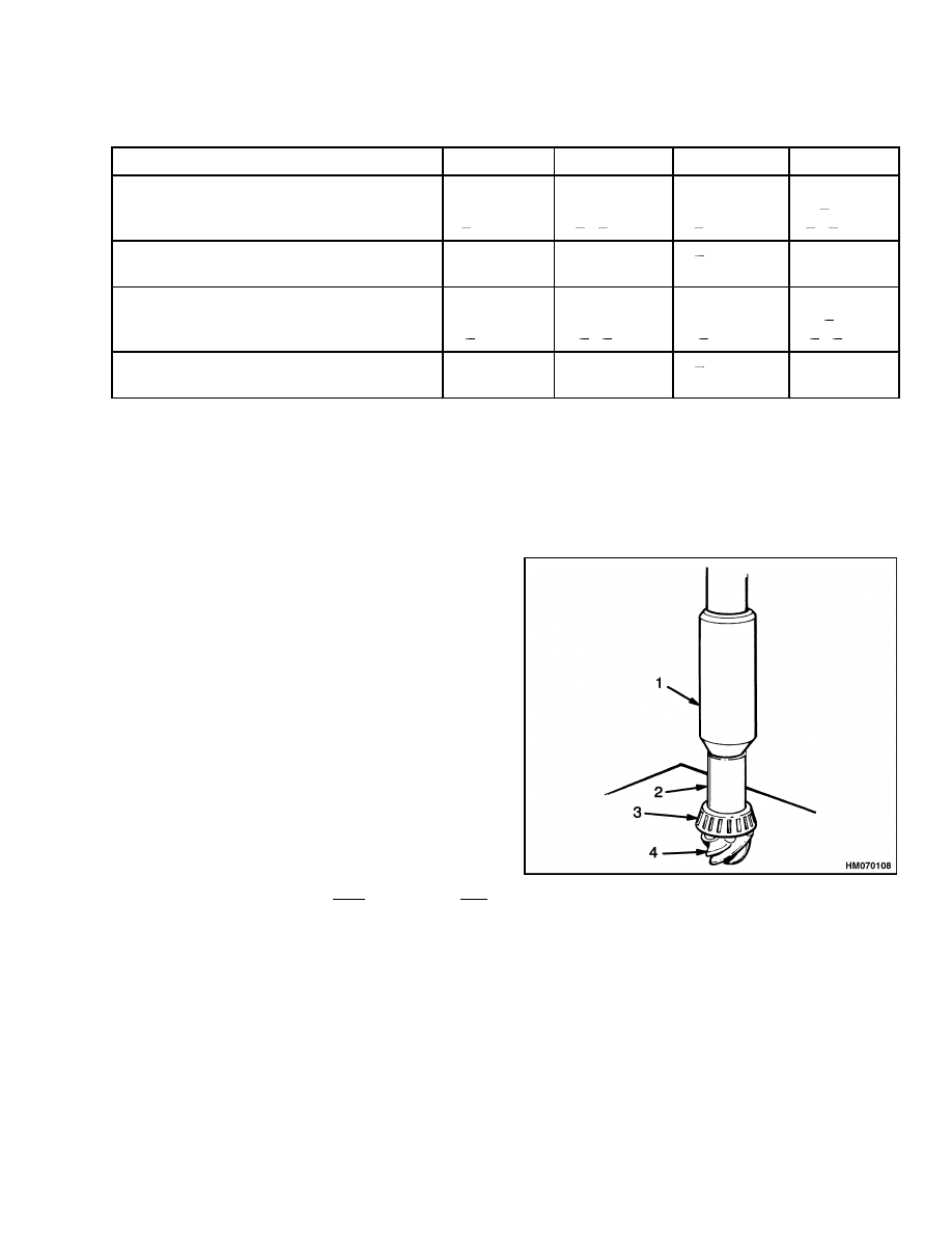
5.
Install the outer bearing cone on the spindle.
Install the washer and lockwasher. Install the
lock nut.
Tighten the nut until the hub can-
not rotate, then loosen nut 30 to 60 until the
hub turns freely. The torque must be less than
27 N•m (20 lbf ft). Tighten the nut to 3.4 N•m
(30 lbf in) or until the first alignment position
after 3.4 N•m (30 lbf in). Bend the lock plate
over the nut. See Figure 18.
Figure 18. Lockwasher Installation
6.
Adjust the clearance of the brake shoes as de-
scribed in the section Brake System 1800 SRM
620.
7.
Make sure the surfaces are clean with no old
sealant and put liquid sealant on the flange of the
axle shaft. See Figure 19. Install the axle shafts.
Install the two capscrews and tighten them.
Figure 19. Put Liquid Sealant on Axle Flange
NOTE: If any of the studs for the drive wheels are
damaged, the studs must be replaced. Use two nuts
tightened together on the stud to remove the old stud.
It can be necessary to heat the stud area to remove
a stud. Use Loctite
®
on the replacement stud. Use
two nuts tightened together on the stud and tighten
the stud to 30 to 50 N•m (22 to 37 lbf ft). Remove the
two installation nuts.
15
Installation of Drive Unit
1400 SRM 618
Installation of Drive Unit
NOTE: The drive unit can be installed with the trac-
tion motor installed on the assembly. Use the reverse
of the procedure Remove Complete Drive Unit As-
sembly as a Unit of this section. The motor can also
be installed with the drive axle and speed reducer in
the lift truck as described in Traction Motor, Install
in this section.
DRIVE UNIT, INSTALL
WARNING
The drive axle, speed reducer, and traction
motor are heavy. Make sure that any lifting
device has enough capacity to lift the weight.
The complete drive unit assembly can weigh
approximately 300 kg (660 lb).
1.
Use a lift truck or crane to move the drive unit as-
sembly to the floor in front of the lift truck. Slide
the drive unit assembly into position under the
lift truck. See Figure 20. The lower edge of the
speed reducer housing MUST be under the frame
crossmember so that the drive unit assembly can
be aligned with the frame.
NOTE: DRIVE UNIT IS DIFFERENT. PROCEDURE IS
THE SAME.
Figure 20. Prepare to Install Drive Unit
2.
Use a crane or another lift truck to raise the drive
unit from the floor so that the drive wheels can
be installed. Install the drive wheels. Tighten
the wheel bolts to 330 N•m (244 lbf ft).
3.
Lubricate the trunnions with multipurpose
grease. Align the axle with the trunnions and
the frame.
Do NOT damage the brake lines,
parking brake cables, electrical wires, or cables
or any hydraulic lines or hoses. Install the trun-
nion caps and tighten the capscrews to 71 to
83 N•m (52 to 61 lbf ft). Install the left frame
mount capscrew, washer, and lock nut to fasten
the speed reducer to the frame.
Tighten the
capscrew and lock nut to 216 N•m (159 lbf ft).
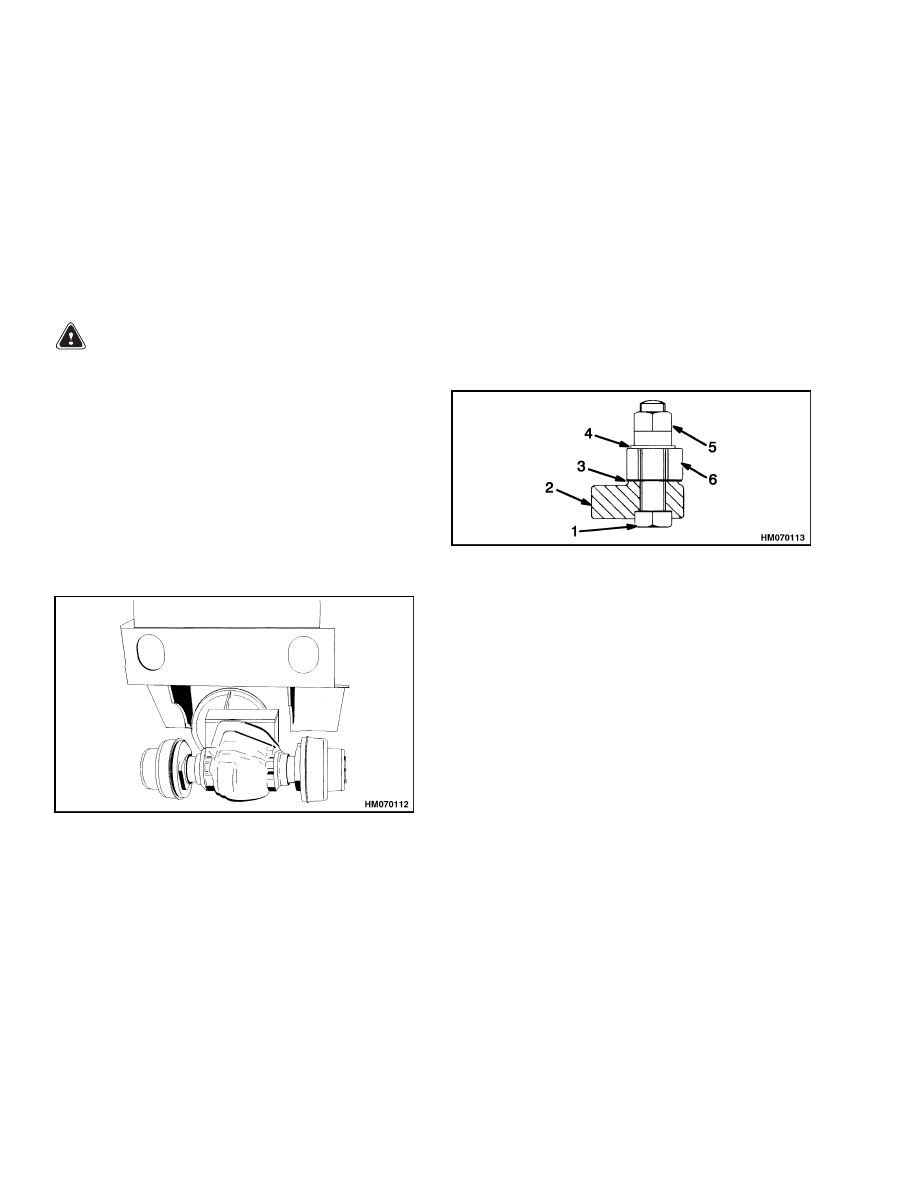
Install shims for zero clearance between the
right-hand mount of the speed reducer and the
frame. Install the mount capscrew, washer, and
lock nut to fasten the speed reducer to the frame.
See Figure 21. Tighten the capscrew and lock
nut to 216 N•m (159 lbf ft).
1.
CAPSCREW
2.
LIFT TRUCK
FRAME
3.
SHIMS
4.
WASHER
5.
LOCK NUT
6.
SPEED REDUCER
HOUSING
Figure 21. Shim Placement
4.
Put the drive wheels of the lift truck on blocks.
Connect the parking brake cables as described in
the section Brake System 1800 SRM 620. Fas-
ten the assembly to the frame.
5.
Connect the brake lines to the wheel cylinders.
Make sure there is brake fluid in the reservoir.
Remove the air from the brake lines. See the
NOTE below.
NOTE: Make sure that a small hose is installed from
the special fitting to a container for brake fluid when
air is removed from the brake lines. If brake fluid
is permitted to flow freely over the parts of the drive
axle in this area, it can cause problems in the lubri-
cation in the mast pivots and cause early failure of
some grease seals.
6.
Adjust the clearance of the brake shoes as de-
scribed in the section Brake System 1800 SRM
620.
16
1400 SRM 618
Installation of Drive Unit
7.
On lift truck models E1.50-1.75XM, E2.00XMS
(E25-40XMS, E25-40XM
2
S) (D114), if there is
a seat brake, install the seat brake spring and
pivot in the reverse order of removal.
8.
Install the traction motor. See Traction Motor,
Install for procedures to install the traction mo-
tor.
9.
Install and tighten the drain plug. Fill the axle
housing with Ultra Gear Lubrication Gear Oil
®
SAE 80W (Chevron) through the fill hole until
the oil level is even with the bottom of the fill
hole. Install the plug.
10. Install the mast. See the section Mast, Repairs
4000 SRM 522 for the procedures. Install the
battery as described in the Operating Manual
or Periodic Maintenance manual for your lift
truck model. Remove the blocks so that the lift
truck is on its wheels.
TRACTION MOTOR, INSTALL
NOTE: Remove the steering pump and motor for
more clearance.
See the section Steering Sys-
tem for Electric Lift Trucks 1600 SRM 485 for
trucks
E1.50-1.75XM,
E2.00XMS
(E25-40XMS,
E25-40XM
2
S) (D114) and the section Steering
System for AC Electric Lift Trucks 1600 SRM
1054 for lift trucks E1.50-2.00XM (E25-35Z, E40ZS)
(E114).
WARNING
The motor is heavy. Make sure that any lifting
device has enough capacity to lift the weight.
The motor can weigh approximately 90 to
140 kg (200 to 310 lb).
1.
Make sure the mount surfaces of the motor and
speed reducer housing are clean, with no old ad-
hesive.
2.
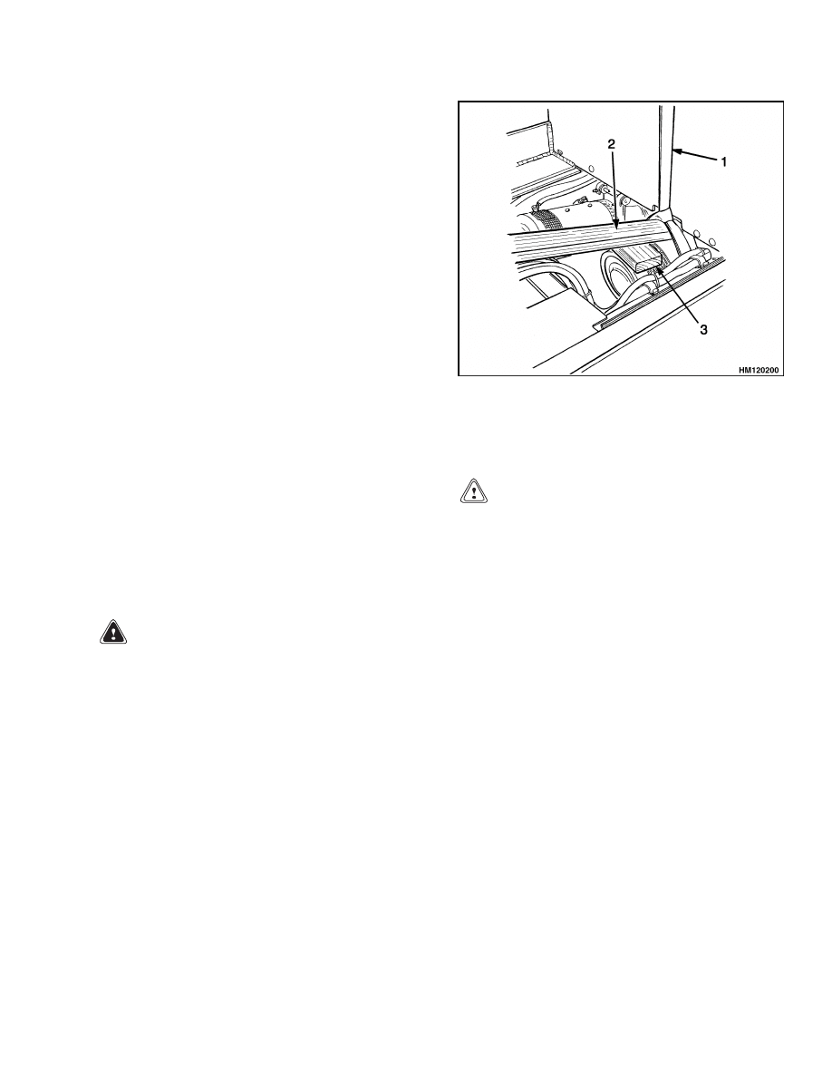
Install a sling to lift the traction motor. Use a
wood block and a board under the sling as shown
in Figure 22 to control the traction motor during
installation.
1.
SLING
2.
BOARD
3.
WOOD BLOCK
Figure 22. Align Traction Motor With Speed
Reducer
CAUTION
There must be 0 to 0.15 mm (0 to 0.006 in.) clear-
ance between the bearing for the input gear of
the speed reducer and the traction motor hous-
ing. Shims must be installed, if necessary, for
this clearance.
3.
Find the correct shim set as follows (see Fig-
ure 10):
a. Install the spacer against the bearing re-
tainer.
b. Use a straight edge, which is shorter than the
bore diameter, across the face of the bearing
and spacer.
c.
If there is clearance between the straight
edge and the spacer, shims must be added
in front of the spacer. If there is clearance
between the straight edge and the bearing,
the clearance must be less than 0.15 mm
(0.006 in.). Measure the clearance using a
thickness gauge.
17

Torque Specifications
1400 SRM 618
d. If the clearance of Step c is at the spacer, add
shims so that there is no clearance at the
spacer. The shims are 0.1, 0.2, and 0.4 mm
(0.004, 0.008, and 0.016 in.) thick. Use the
combination of shims to remove all the clear-
ance at the spacer. There must also be no
more than 0.15 mm (0.006 in.) clearance at
the bearing. Install the shims in front of the
spacer.
e.
Do Step b and Step c again to make sure
that there is no clearance at the face of the
shims. There must also be 0 to 0.15 mm (0 to
0.006 in.) clearance at the face of the bear-
ing.
4.
Lower the traction motor into position.
Align
the traction motor with the speed reducer. Make
sure the spacer and shims of Step 3 are installed
in the speed reducer housing.
5.
Make sure the surface of the speed reducer and
motor housings are clean, with no adhesive.
Apply liquid adhesive (Hyster Part Number
264159) to seal the motor-to-speed reducer hous-
ings.
6.
Use a board or pry bar as necessary to carefully
push the traction motor into the speed reducer.
7.
Align the bolt holes in the speed reducer and the
motor housing. Install the six bolts that hold the
traction motor to the speed reducer. Tighten the
bolts to 71 to 83 N•m (52 to 61 lbf ft).
NOTE: If the drive unit assembly is in the lift truck,
continue with this procedure. If the drive unit as-
sembly is out of the lift truck, install the drive unit
assembly. See Drive Unit, Install of this section.
8.
Connect the inlet hydraulic line to the main con-
trol valve. Install the power cables. Connect the
wires for the brush wear indicator and the ther-
mal switch if installed.
9.
On lift truck models E1.50-1.75XM, E2.00XMS
(E25-40XMS, E25-40XM
2
S) (D114), if there is a
seat brake, put a weight on the seat that will
hold the seat in the down position. Connect the
spring between the linkage and the brake as-
sembly. Install the nut, capscrew, washers, and
bushing at the pivot of the brake linkage as re-
moved. Tighten the capscrew and nut to 40 N•m
(30 lbf ft).
10. If removed, install the steering pump and motor
as described in the section Steering System
for Electric Lift Trucks 1600 SRM 485 for
trucks E1.50-1.75XM, E2.00XMS (E25-40XMS,
E25-40XM
2
S) (D114) and the section Steer-
ing System for AC Electric Lift Trucks
1600 SRM 1054 for lift trucks E1.50-2.00XM
(E25-35Z, E40ZS) (E114).
Torque Specifications
Capscrews for Axle Trunnion Caps
71 to 83 N•m (52 to 61 lbf ft)
Traction Motor Mount Capscrews
71 to 83 N•m (52 to 61 lbf ft)
Speed Reducer Support Capscrews
216 N•m (159 lbf ft)
Speed Reducer-to-Axle Capscrews
41 to 49 N•m (30 to 36 lbf ft)
Speed Reducer Cover Capscrews
21 to 25 N•m (15 to 18 lbf ft)
Pinion Lock Nut (Rotating Torque)
5.4 to 5.9 N•m (48 to 52 lbf in)
Differential Bearing Nuts (Rotating Torque)
2.9 to 3.4 N•m (26 to 30 lbf in)
Bearing Cap Capscrews 263 to 315 N•m
(194 to 233 lbf ft)
Ring Gear Capscrews
152 to 167 N•m (112 to 123 lbf ft)
Mount Bolts for Brake Assembly (Back Plate)
152 to 167 N•m (112 to 123 lbf ft)
Hub Lock Nut
Initial: 200 N•m (148 lbf ft) while rotating hub
Final: 3.4 N•m (30 lbf in)
Wheel Bolts
330 N•m (244 lbf ft)
18

1400 SRM 618
Troubleshooting
Troubleshooting
PROBLEM
POSSIBLE CAUSE
PROCEDURE OR ACTION
The lift truck will not move.
An axle shaft is broken.
Install new axle shaft.
The differential is damaged.
Repair differential.
The drive axle has leaks.
The drain or fill plug has damaged
threads, is loose, or is missing.
Repair threads. Tighten plug. Install
missing part.
The O-rings or seals have damage.
Install new O-rings and seals.
The drive axle housing is cracked.
Install new drive axle housing.
The drive axle makes noise.
The bearings have damage.
Install new parts.
The brake assembly is damaged.
Repair brake assembly.
The oil level is low.
Fill as required. Check for leaks.
The axle mounting capscrews are
loose.
Tighten
capscrews
to
specified
torque.
19

NOTES
____________________________________________________________
____________________________________________________________
____________________________________________________________
____________________________________________________________
____________________________________________________________
____________________________________________________________
____________________________________________________________
____________________________________________________________
____________________________________________________________
____________________________________________________________
____________________________________________________________
____________________________________________________________
____________________________________________________________
____________________________________________________________
____________________________________________________________
____________________________________________________________
____________________________________________________________
____________________________________________________________
____________________________________________________________
____________________________________________________________
20


TECHNICAL PUBLICATIONS
1400 SRM 618
6/04 (2/04)(6/02)(7/99)(5/96) Printed in United Kingdom
Document Outline
- toc
- tables
Wyszukiwarka
Podobne podstrony:
1554635 8000SRM1079 (06 2004) UK EN
897480 1400SRM0499 (10 2004) UK EN
897067 1400SRM0285 (05 2004) UK EN
1565454 8000SRM1113 (06 2004) UK EN
910030 1400SRM0047 (08 2004) UK EN
1554632 2000SRM1086 (06 2004) UK EN
897494 1900SRM0513 (06 2004) UK EN
1554626 0100SRM1073 (06 2004) UK EN
1554630 1900SRM1077 (06 2004) UK EN
897559 0100SRM0545 (06 2004) UK EN
897881 1600SRM0619 (06 2004) UK EN
1554635 8000SRM1079 (06 2004) UK EN
897480 1400SRM0499 (10 2004) UK EN
więcej podobnych podstron