1 - 18
CCNP: Building Scalable Internetworks v5.0 - Lab 3-2
Copyright
© 2006, Cisco Systems, Inc
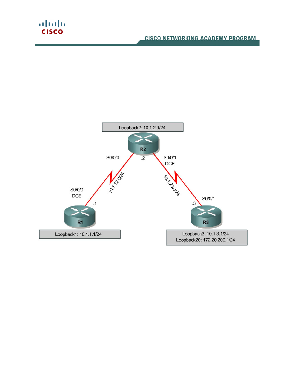
Lab 3-2 Multiple-Area OSPF with Stub Areas and Authentication
Learning Objectives
• Configure
multiple-area OSPF on a router
• Verify multiple-area behavior
• Configure OSPF stub, totally stubby, and not so stubby areas
• Configure
OSPF
authentication
Topology
Scenario
You are responsible for configuring the new network to connect your company’s
Engineering, Marketing, and Accounting departments, represented by loopback
interfaces on each of the three routers. The physical devices have just been
installed and connected by serial cables. Configure multiple-area OSPF to allow
full connectivity between all departments.
R3 will also have a loopback representing a connection to another autonomous
system that is not part of OSPF.
This topology may appear again in future labs, so save your configuration.

2 - 18
CCNP: Building Scalable Internetworks v5.0 - Lab 3-2
Copyright
© 2006, Cisco Systems, Inc
Step 1: Addressing
Set up the physical serial interfaces on R1, R2, and R3 with IP addresses, and
bring them up. Depending on which router models you have, you may need to
add clock rates to the DCE end of each connection (newer equipment adds this
automatically). Verify that you can ping across each serial link. Add the
loopbacks shown in the diagram to each router.
R1# configure terminal
Enter configuration commands, one per line. End with CNTL/Z.
R1(config)# interface loopback 1
R1(config-if)# ip address 10.1.1.1 255.255.255.0
R1(config-if)# interface serial 0/0/0
R1(config-if)# ip address 10.1.12.1 255.255.255.0
R1(config-if)# clockrate 64000
R1(config-if)# no shutdown
R2# configure terminal
Enter configuration commands, one per line. End with CNTL/Z.
R2(config)# interface loopback 2
R2(config-if)# ip address 10.1.2.1 255.255.255.0
R2(config-if)# interface serial 0/0/0
R2(config-if)# ip address 10.1.12.2 255.255.255.0
R2(config-if)# no shutdown
R2(config-if)# interface serial 0/0/1
R2(config-if)# ip address 10.1.23.2 255.255.255.0
R2(config-if)# clockrate 64000
R2(config-if)# no shutdown
R3# configure terminal
Enter configuration commands, one per line. End with CNTL/Z.
R3(config)# interface loopback 3
R3(config-if)# ip address 10.1.3.1 255.255.255.0
R3(config-if)# interface loopback 20
R3(config-if)# ip address 172.20.200.1 255.255.255.0
R3(config-if)# interface serial 0/0/1
R3(config-if)# ip address 10.1.23.1 255.255.255.0
R3(config-if)# no shutdown
Step 2: Adding Interfaces into OSPF
Create OSPF process 1 on all three routers. Configure the subnet of the serial
link between R1 and R2 to be in OSPF area 0 using the network command.
Add loopback 1 on R1 and loopback 2 on R2 into OSPF area 0. Verify that you
can see OSPF neighbors in the show ip ospf neighbors output on both
routers and that they can see each other’s loopback with the show ip route
command. Change the network type on the loopback interfaces so that they are
advertised with the correct subnet.
R1(config)# router ospf 1
R1(config-router)# network 10.1.12.0 0.0.0.255 area 0
R1(config-router)# network 10.1.1.0 0.0.0.255 area 0
R1(config-router)# interface loopback 1
R1(config-if)# ip ospf network point-to-point
R2(config)# router ospf 1
R2(config-router)# network 10.1.12.0 0.0.0.255 area 0
R2(config-router)# network 10.1.2.0 0.0.0.255 area 0

3 - 18
CCNP: Building Scalable Internetworks v5.0 - Lab 3-2
Copyright
© 2006, Cisco Systems, Inc
R2(config-router)# interface loopback 2
R2(config-if)# ip ospf network point-to-point
R1# show ip ospf neighbor
Neighbor ID Pri State Dead Time Address Interface
10.1.2.1 0 FULL/ - 00:00:38 10.1.12.2 Serial0/0/0
R1# show ip route
Codes: C - connected, S - static, R - RIP, M - mobile, B - BGP
D - EIGRP, EX - EIGRP external, O - OSPF, IA - OSPF inter area
N1 - OSPF NSSA external type 1, N2 - OSPF NSSA external type 2
E1 - OSPF external type 1, E2 - OSPF external type 2
i - IS-IS, su - IS-IS summary, L1 - IS-IS level-1, L2 - IS-IS level-2
ia - IS-IS inter area, * - candidate default, U - per-user static route
o - ODR, P - periodic downloaded static route
Gateway of last resort is not set
10.0.0.0/24 is subnetted, 3 subnets
C 10.1.12.0 is directly connected, Serial0/0/0
O 10.1.2.0 [110/65] via 10.1.12.2, 00:00:10, Serial0/0/0
C 10.1.1.0 is directly connected, Loopback1
R2# show ip ospf neighbor
Neighbor ID Pri State Dead Time Address Interface
10.1.1.1 0 FULL/ - 00:00:35 10.1.12.1 Serial0/0/0
R2# show ip route
Codes: C - connected, S - static, R - RIP, M - mobile, B - BGP
D - EIGRP, EX - EIGRP external, O - OSPF, IA - OSPF inter area
N1 - OSPF NSSA external type 1, N2 - OSPF NSSA external type 2
E1 - OSPF external type 1, E2 - OSPF external type 2
i - IS-IS, su - IS-IS summary, L1 - IS-IS level-1, L2 - IS-IS level-2
ia - IS-IS inter area, * - candidate default, U - per-user static route
o - ODR, P - periodic downloaded static route
Gateway of last resort is not set
10.0.0.0/24 is subnetted, 4 subnets
C 10.1.12.0 is directly connected, Serial0/0/0
C 10.1.2.0 is directly connected, Loopback2
O 10.1.1.0 [110/65] via 10.1.12.1, 00:00:30, Serial0/0/0
C 10.1.23.0 is directly connected, Serial0/0/1
Add the subnet between R2 and R3 into OSPF area 23 using the network
command. Add loopback 3 on R3 into area 23. Verify that this neighbor
relationship comes up using the show ip ospf neighbors command.
R2(config)# router ospf 1
R2(config-router)# network 10.1.23.0 0.0.0.255 area 23
R3(config)# router ospf 1
R3(config-router)# network 10.1.23.0 0.0.0.255 area 23
R3(config-router)# network 10.1.3.0 0.0.0.255 area 23
R3(config-router)# interface loopback 3
R3(config-if)# ip ospf network point-to-point
R2# show ip ospf neighbor
Neighbor ID Pri State Dead Time Address Interface

4 - 18
CCNP: Building Scalable Internetworks v5.0 - Lab 3-2
Copyright
© 2006, Cisco Systems, Inc
10.1.1.1 0 FULL/ - 00:00:36 10.1.12.1 Serial0/0/0
172.20.200.1 0 FULL/ - 00:00:36 10.1.23.3 Serial0/0/1
If you look at the output of the show ip route command on R1, you see a route
to R3’s loopback. Notice that it comes in as an inter-area route.
R1# show ip route
Codes: C - connected, S - static, R - RIP, M - mobile, B - BGP
D - EIGRP, EX - EIGRP external, O - OSPF, IA - OSPF inter area
N1 - OSPF NSSA external type 1, N2 - OSPF NSSA external type 2
E1 - OSPF external type 1, E2 - OSPF external type 2
i - IS-IS, su - IS-IS summary, L1 - IS-IS level-1, L2 - IS-IS level-2
ia - IS-IS inter area, * - candidate default, U - per-user static route
o - ODR, P - periodic downloaded static route
Gateway of last resort is not set
10.0.0.0/24 is subnetted, 5 subnets
C 10.1.12.0 is directly connected, Serial0/0/0
O IA 10.1.3.0 [110/129] via 10.1.12.2, 00:00:28, Serial0/0/0
O 10.1.2.0 [110/65] via 10.1.12.2, 00:01:38, Serial0/0/0
C 10.1.1.0 is directly connected, Loopback1
O IA 10.1.23.0 [110/128] via 10.1.12.2, 00:01:38, Serial0/0/0
R2 has no inter-area routes, because R2 is in both areas; it is an ABR, or area
border router.
R2# show ip route
Codes: C - connected, S - static, R - RIP, M - mobile, B - BGP
D - EIGRP, EX - EIGRP external, O - OSPF, IA - OSPF inter area
N1 - OSPF NSSA external type 1, N2 - OSPF NSSA external type 2
E1 - OSPF external type 1, E2 - OSPF external type 2
i - IS-IS, su - IS-IS summary, L1 - IS-IS level-1, L2 - IS-IS level-2
ia - IS-IS inter area, * - candidate default, U - per-user static route
o - ODR, P - periodic downloaded static route
Gateway of last resort is not set
10.0.0.0/24 is subnetted, 5 subnets
C 10.1.12.0 is directly connected, Serial0/0/0
O 10.1.3.0 [110/65] via 10.1.23.3, 00:00:50, Serial0/0/1
C 10.1.2.0 is directly connected, Loopback2
O 10.1.1.0 [110/65] via 10.1.12.1, 00:02:00, Serial0/0/0
C 10.1.23.0 is directly connected, Serial0/0/1
Verify that you can ping all interfaces from any router, with the exception of
loopback 20 on R3, which has not yet been configured as part of OSPF.
Step 3: Stub Areas
Under the OSPF process on R2 and R3, make area 23 the stub area using the
area area stub command. The adjacency between the two routers may go
down during the transition period, but it should come back up afterwards.
Confirm that it comes up by using the show ip ospf neighbors command.
R2(config)# router ospf 1
R2(config-router)# area 23 stub

5 - 18
CCNP: Building Scalable Internetworks v5.0 - Lab 3-2
Copyright
© 2006, Cisco Systems, Inc
R3(config)# router ospf 1
R3(config-router)# area 23 stub
R2# show ip ospf neighbor
Neighbor ID Pri State Dead Time Address Interface
10.1.1.1 0 FULL/ - 00:00:36 10.1.12.1 Serial0/0/0
172.20.200.1 0 FULL/ - 00:00:36 10.1.23.3 Serial0/0/1
R3# show ip ospf neighbor
Neighbor ID Pri State Dead Time Address Interface
10.1.2.1 0 FULL/ - 00:00:31 10.1.23.2 Serial0/0/1
Using the show ip route command, you can see that R3 now has a default
route pointing toward R2. A stub area does not get any external routes. A stub
area receives a default route and OSPF inter area routes.
R3# show ip route
Codes: C - connected, S - static, R - RIP, M - mobile, B - BGP
D - EIGRP, EX - EIGRP external, O - OSPF, IA - OSPF inter area
N1 - OSPF NSSA external type 1, N2 - OSPF NSSA external type 2
E1 - OSPF external type 1, E2 - OSPF external type 2
i - IS-IS, su - IS-IS summary, L1 - IS-IS level-1, L2 - IS-IS level-2
ia - IS-IS inter area, * - candidate default, U - per-user static route
o - ODR, P - periodic downloaded static route
Gateway of last resort is 10.1.23.2 to network 0.0.0.0
172.20.0.0/24 is subnetted, 1 subnets
C 172.20.200.0 is directly connected, Loopback20
10.0.0.0/24 is subnetted, 5 subnets
O IA 10.1.12.0 [110/128] via 10.1.23.2, 00:00:56, Serial0/0/1
C 10.1.3.0 is directly connected, Loopback3
O IA 10.1.2.0 [110/65] via 10.1.23.2, 00:00:56, Serial0/0/1
O IA 10.1.1.0 [110/129] via 10.1.23.2, 00:00:56, Serial0/0/1
C 10.1.23.0 is directly connected, Serial0/0/1
O*IA 0.0.0.0/0 [110/65] via 10.1.23.2, 00:00:56, Serial0/0/1
Take a look at the output of the show ip ospf command to see what type each
area is.
R2# show ip ospf
Routing Process "ospf 1" with ID 10.1.2.1
Supports only single TOS(TOS0) routes
Supports opaque LSA
Supports Link-local Signaling (LLS)
Supports area transit capability
It is an area border router
Initial SPF schedule delay 5000 msecs
Minimum hold time between two consecutive SPFs 10000 msecs
Maximum wait time between two consecutive SPFs 10000 msecs
Incremental-SPF disabled
Minimum LSA interval 5 secs
Minimum LSA arrival 1000 msecs
LSA group pacing timer 240 secs
Interface flood pacing timer 33 msecs
Retransmission pacing timer 66 msecs
Number of external LSA 0. Checksum Sum 0x000000
Number of opaque AS LSA 0. Checksum Sum 0x000000
Number of DCbitless external and opaque AS LSA 0

6 - 18
CCNP: Building Scalable Internetworks v5.0 - Lab 3-2
Copyright
© 2006, Cisco Systems, Inc
Number of DoNotAge external and opaque AS LSA 0
Number of areas in this router is 2. 1 normal 1 stub 0 nssa
Number of areas transit capable is 0
External flood list length 0
Area BACKBONE(0)
Number of interfaces in this area is 2
Area has no authentication
SPF algorithm last executed 00:02:11.680 ago
SPF algorithm executed 5 times
Area ranges are
Number of LSA 4. Checksum Sum 0x01A85A
Number of opaque link LSA 0. Checksum Sum 0x000000
Number of DCbitless LSA 0
Number of indication LSA 0
Number of DoNotAge LSA 0
Flood list length 0
Area 23
Number of interfaces in this area is 1
It is a stub area
generates stub default route with cost 1
Area has no authentication
SPF algorithm last executed 00:01:38.276 ago
SPF algorithm executed 8 times
Area ranges are
Number of LSA 6. Checksum Sum 0x027269
Number of opaque link LSA 0. Checksum Sum 0x000000
Number of DCbitless LSA 0
Number of indication LSA 0
Number of DoNotAge LSA 0
Flood list length 0
What advantages would be gained by having a router get a default route rather
than a more specific route?
Why do all routers in a stub area need to know that that area is a stub?
Step 4: Totally Stubby Areas
A modified version of a stubby area is a totally stubby area. A totally stubby
area ABR only allows in a single, default route from the backbone. To configure
this, you only need to change a command at the ABR, in our case, R2. Under
the router OSPF process, enter the area 23 stub no-summary command. This
replaces the existing stub command for area 23. no-summary tells the router
that this area will not receive summary (inter-area) routes.

7 - 18
CCNP: Building Scalable Internetworks v5.0 - Lab 3-2
Copyright
© 2006, Cisco Systems, Inc
To see how this works, first issue the show ip route command on R3. Notice
the inter-area routes in addition to the default route generated by R2. Also, look
at show ip ospf database on R2 to see what LSAs are in its OSPF database.
R3# show ip route
Codes: C - connected, S - static, R - RIP, M - mobile, B - BGP
D - EIGRP, EX - EIGRP external, O - OSPF, IA - OSPF inter area
N1 - OSPF NSSA external type 1, N2 - OSPF NSSA external type 2
E1 - OSPF external type 1, E2 - OSPF external type 2
i - IS-IS, su - IS-IS summary, L1 - IS-IS level-1, L2 - IS-IS level-2
ia - IS-IS inter area, * - candidate default, U - per-user static route
o - ODR, P - periodic downloaded static route
Gateway of last resort is 10.1.23.2 to network 0.0.0.0
172.20.0.0/24 is subnetted, 1 subnets
C 172.20.200.0 is directly connected, Loopback20
10.0.0.0/24 is subnetted, 5 subnets
O IA 10.1.12.0 [110/128] via 10.1.23.2, 00:00:56, Serial0/0/1
C 10.1.3.0 is directly connected, Loopback3
O IA 10.1.2.0 [110/65] via 10.1.23.2, 00:00:56, Serial0/0/1
O IA 10.1.1.0 [110/129] via 10.1.23.2, 00:00:56, Serial0/0/1
C 10.1.23.0 is directly connected, Serial0/0/1
O*IA 0.0.0.0/0 [110/65] via 10.1.23.2, 00:00:56, Serial0/0/1
R2# show ip ospf database
OSPF Router with ID (10.1.2.1) (Process ID 1)
Router Link States (Area 0)
Link ID ADV Router Age Seq# Checksum Link count
10.1.1.1 10.1.1.1 435 0x80000004 0x0056D6 3
10.1.2.1 10.1.2.1 358 0x80000003 0x0057D2 3
Summary Net Link States (Area 0)
Link ID ADV Router Age Seq# Checksum
10.1.3.0 10.1.2.1 174 0x80000001 0x00EFEF
10.1.23.0 10.1.2.1 354 0x80000001 0x0009C3
Router Link States (Area 23)
Link ID ADV Router Age Seq# Checksum Link count
10.1.2.1 10.1.2.1 188 0x80000004 0x00298C 2
172.20.200.1 172.20.200.1 188 0x80000004 0x00B762 3
Summary Net Link States (Area 23)
Link ID ADV Router Age Seq# Checksum
0.0.0.0 10.1.2.1 207 0x80000001 0x003BF4
10.1.1.0 10.1.2.1 209 0x80000002 0x0022C0
10.1.2.0 10.1.2.1 209 0x80000002 0x00948D
10.1.12.0 10.1.2.1 209 0x80000002 0x009E3A
Now, enter the no-summary stub command on R2 (the ABR) under the OSPF
process.
R2(config)# router ospf 1
R2(config-router)# area 23 stub no-summary

8 - 18
CCNP: Building Scalable Internetworks v5.0 - Lab 3-2
Copyright
© 2006, Cisco Systems, Inc
Go back to R3 and look at show ip route again. Notice that it only has one
incoming route from OSPF. Also look at the show ip ospf database output to
see which routes are in area 23.
R3# show ip route
Codes: C - connected, S - static, R - RIP, M - mobile, B - BGP
D - EIGRP, EX - EIGRP external, O - OSPF, IA - OSPF inter area
N1 - OSPF NSSA external type 1, N2 - OSPF NSSA external type 2
E1 - OSPF external type 1, E2 - OSPF external type 2
i - IS-IS, su - IS-IS summary, L1 - IS-IS level-1, L2 - IS-IS level-2
ia - IS-IS inter area, * - candidate default, U - per-user static route
o - ODR, P - periodic downloaded static route
Gateway of last resort is 10.1.23.2 to network 0.0.0.0
172.20.0.0/24 is subnetted, 1 subnets
C 172.20.200.0 is directly connected, Loopback20
10.0.0.0/24 is subnetted, 2 subnets
C 10.1.3.0 is directly connected, Loopback3
C 10.1.23.0 is directly connected, Serial0/0/1
O*IA 0.0.0.0/0 [110/65] via 10.1.23.2, 00:00:10, Serial0/0/1
R2# show ip ospf database
OSPF Router with ID (10.1.2.1) (Process ID 1)
Router Link States (Area 0)
Link ID ADV Router Age Seq# Checksum Link count
10.1.1.1 10.1.1.1 522 0x80000004 0x0056D6 3
10.1.2.1 10.1.2.1 445 0x80000003 0x0057D2 3
Summary Net Link States (Area 0)
Link ID ADV Router Age Seq# Checksum
10.1.3.0 10.1.2.1 261 0x80000001 0x00EFEF
10.1.23.0 10.1.2.1 441 0x80000001 0x0009C3
Router Link States (Area 23)
Link ID ADV Router Age Seq# Checksum Link count
10.1.2.1 10.1.2.1 275 0x80000004 0x00298C 2
172.20.200.1 172.20.200.1 276 0x80000004 0x00B762 3
Summary Net Link States (Area 23)
Link ID ADV Router Age Seq# Checksum
0.0.0.0 10.1.2.1 68 0x80000002 0x0039F5
What advantages would there be in making an area totally stubby instead of a
regular stub area? What are the disadvantages?
Why did only the ABR need to know that the area was totally stubby rather than
all routers in the area?

9 - 18
CCNP: Building Scalable Internetworks v5.0 - Lab 3-2
Copyright
© 2006, Cisco Systems, Inc
Step 5: Not So Stubby Areas
Not so stubby areas (NSSAs) are similar to regular stub areas, except that they
allow routes to be redistributed from an ASBR into that area with a special LSA
type, which gets converted to a normal external route at the ABR. For this lab,
we will change area 23 into an NSSA. NSSAs are not compatible with stub
areas, so the first thing we must do is issue a no area 23 stub command on
routers R2 and R3.
Next, we issue the area area nssa command on routers R2 and R3 to change
area 23 to an NSSA. To generate an external route into the NSSA, use the
redistribute connected subnets command on R3. This adds the previously
unreachable loopback 20 into OSPF. Be sure to include the subnets keyword;
otherwise, only classful networks are redistributed.
R2(config)# router ospf 1
R2(config-router)# no area 23 stub
R2(config-router)# area 23 nssa
R3(config)# router ospf 1
R3(config-router)# no area 23 stub
R3(config-router)# area 23 nssa
R3(config-router)# redistribute connected subnets
Take a look at the output of show ip ospf on R2. Notice that area 23 is an
NSSA and that R2 is performing the LSA type 7 to type 5 translation. If there
are multiple ABRs to an NSSA, the ABR with the highest router ID performs the
translation.
R2# show ip ospf
Routing Process "ospf 1" with ID 10.1.2.1
Supports only single TOS(TOS0) routes
Supports opaque LSA
Supports Link-local Signaling (LLS)
Supports area transit capability
It is an area border and autonomous system boundary router
Redistributing External Routes from,
Initial SPF schedule delay 5000 msecs
Minimum hold time between two consecutive SPFs 10000 msecs
Maximum wait time between two consecutive SPFs 10000 msecs
Incremental-SPF disabled
Minimum LSA interval 5 secs
Minimum LSA arrival 1000 msecs
LSA group pacing timer 240 secs
Interface flood pacing timer 33 msecs
Retransmission pacing timer 66 msecs
Number of external LSA 1. Checksum Sum 0x00CA2F
Number of opaque AS LSA 0. Checksum Sum 0x000000
Number of DCbitless external and opaque AS LSA 0
Number of DoNotAge external and opaque AS LSA 0
Number of areas in this router is 2. 1 normal 0 stub 1 nssa
Number of areas transit capable is 0
External flood list length 0
Area BACKBONE(0)
Number of interfaces in this area is 2
Area has no authentication

10 - 18
CCNP: Building Scalable Internetworks v5.0 - Lab 3-2
Copyright
© 2006, Cisco Systems, Inc
SPF algorithm last executed 00:03:11.636 ago
SPF algorithm executed 9 times
Area ranges are
Number of LSA 4. Checksum Sum 0x01AC53
Number of opaque link LSA 0. Checksum Sum 0x000000
Number of DCbitless LSA 0
Number of indication LSA 0
Number of DoNotAge LSA 0
Flood list length 0
Area 23
Number of interfaces in this area is 1
It is a NSSA area
Perform type-7/type-5 LSA translation
Area has no authentication
SPF algorithm last executed 00:00:16.408 ago
SPF algorithm executed 16 times
Area ranges are
Number of LSA 6. Checksum Sum 0x025498
Number of opaque link LSA 0. Checksum Sum 0x000000
Number of DCbitless LSA 0
Number of indication LSA 0
Number of DoNotAge LSA 0
Flood list length 0
Now look at the show ip route output on R2. Notice that the “external” route
comes in as type N2 from R3. This is because it is a special NSSA external
route.
R2# show ip route
Codes: C - connected, S - static, R - RIP, M - mobile, B - BGP
D - EIGRP, EX - EIGRP external, O - OSPF, IA - OSPF inter area
N1 - OSPF NSSA external type 1, N2 - OSPF NSSA external type 2
E1 - OSPF external type 1, E2 - OSPF external type 2
i - IS-IS, su - IS-IS summary, L1 - IS-IS level-1, L2 - IS-IS level-2
ia - IS-IS inter area, * - candidate default, U - per-user static route
o - ODR, P - periodic downloaded static route
Gateway of last resort is not set
172.20.0.0/24 is subnetted, 1 subnets
O N2 172.20.200.0 [110/20] via 10.1.23.3, 00:00:41, Serial0/0/1
10.0.0.0/24 is subnetted, 5 subnets
C 10.1.12.0 is directly connected, Serial0/0/0
O 10.1.3.0 [110/65] via 10.1.23.3, 00:00:47, Serial0/0/1
C 10.1.2.0 is directly connected, Loopback2
O 10.1.1.0 [110/65] via 10.1.12.1, 00:03:42, Serial0/0/0
C 10.1.23.0 is directly connected, Serial0/0/1
Look at the show ip route output on R1. Notice that now the route is a regular
E2 external route, because R2 has performed the type 7 to type 5 translation.
R1# show ip route
Codes: C - connected, S - static, R - RIP, M - mobile, B - BGP
D - EIGRP, EX - EIGRP external, O - OSPF, IA - OSPF inter area
N1 - OSPF NSSA external type 1, N2 - OSPF NSSA external type 2
E1 - OSPF external type 1, E2 - OSPF external type 2
i - IS-IS, su - IS-IS summary, L1 - IS-IS level-1, L2 - IS-IS level-2
ia - IS-IS inter area, * - candidate default, U - per-user static route
o - ODR, P - periodic downloaded static route
Gateway of last resort is not set

11 - 18
CCNP: Building Scalable Internetworks v5.0 - Lab 3-2
Copyright
© 2006, Cisco Systems, Inc
172.20.0.0/24 is subnetted, 1 subnets
O E2 172.20.200.0 [110/20] via 10.1.12.2, 00:01:22, Serial0/0/0
10.0.0.0/24 is subnetted, 5 subnets
C 10.1.12.0 is directly connected, Serial0/0/0
O IA 10.1.3.0 [110/129] via 10.1.12.2, 00:02:06, Serial0/0/0
O 10.1.2.0 [110/65] via 10.1.12.2, 00:04:22, Serial0/0/0
C 10.1.1.0 is directly connected, Loopback1
O IA 10.1.23.0 [110/128] via 10.1.12.2, 00:04:22, Serial0/0/0
If you look at the show ip route output on R3, you may notice that it no longer
has a default route in it, but inter-area routes are coming in.
R3# show ip route
Codes: C - connected, S - static, R - RIP, M - mobile, B - BGP
D - EIGRP, EX - EIGRP external, O - OSPF, IA - OSPF inter area
N1 - OSPF NSSA external type 1, N2 - OSPF NSSA external type 2
E1 - OSPF external type 1, E2 - OSPF external type 2
i - IS-IS, su - IS-IS summary, L1 - IS-IS level-1, L2 - IS-IS level-2
ia - IS-IS inter area, * - candidate default, U - per-user static route
o - ODR, P - periodic downloaded static route
Gateway of last resort is not set
172.20.0.0/24 is subnetted, 1 subnets
C 172.20.200.0 is directly connected, Loopback20
10.0.0.0/24 is subnetted, 5 subnets
O IA 10.1.12.0 [110/128] via 10.1.23.2, 00:02:11, Serial0/0/1
C 10.1.3.0 is directly connected, Loopback3
O IA 10.1.2.0 [110/65] via 10.1.23.2, 00:02:11, Serial0/0/1
O IA 10.1.1.0 [110/129] via 10.1.23.2, 00:02:11, Serial0/0/1
C 10.1.23.0 is directly connected, Serial0/0/1
We can change this by making the area a totally not so stubby area. To
configure this, issue the area 23 nssa no-summary command on R2, similar to
converting a stub area into a totally stubby area. Then, check the routing table
on R3 and notice that the inter-area routes have been replaced by a single
default route.
R2(config)# router ospf 1
R2(config-router)# area 23 nssa no-summary
R3# show ip route
Codes: C - connected, S - static, R - RIP, M - mobile, B - BGP
D - EIGRP, EX - EIGRP external, O - OSPF, IA - OSPF inter area
N1 - OSPF NSSA external type 1, N2 - OSPF NSSA external type 2
E1 - OSPF external type 1, E2 - OSPF external type 2
i - IS-IS, su - IS-IS summary, L1 - IS-IS level-1, L2 - IS-IS level-2
ia - IS-IS inter area, * - candidate default, U - per-user static route
o - ODR, P - periodic downloaded static route
Gateway of last resort is 10.1.23.2 to network 0.0.0.0
172.20.0.0/24 is subnetted, 1 subnets
C 172.20.200.0 is directly connected, Loopback20
10.0.0.0/24 is subnetted, 2 subnets
C 10.1.3.0 is directly connected, Loopback3
C 10.1.23.0 is directly connected, Serial0/0/1
O*IA 0.0.0.0/0 [110/65] via 10.1.23.2, 00:00:20, Serial0/0/1

12 - 18
CCNP: Building Scalable Internetworks v5.0 - Lab 3-2
Copyright
© 2006, Cisco Systems, Inc
Also on R2, take a look at the show ip ospf database output to see the various
LSA types.
R2# show ip ospf database
OSPF Router with ID (10.1.2.1) (Process ID 1)
Router Link States (Area 0)
Link ID ADV Router Age Seq# Checksum Link count
10.1.1.1 10.1.1.1 944 0x80000004 0x0056D6 3
10.1.2.1 10.1.2.1 383 0x80000004 0x005BCB 3
Summary Net Link States (Area 0)
Link ID ADV Router Age Seq# Checksum
10.1.3.0 10.1.2.1 242 0x80000001 0x00EFEF
10.1.23.0 10.1.2.1 862 0x80000001 0x0009C3
Router Link States (Area 23)
Link ID ADV Router Age Seq# Checksum Link count
10.1.2.1 10.1.2.1 257 0x80000007 0x00B0F7 2
172.20.200.1 172.20.200.1 209 0x80000007 0x003FCD 3
Summary Net Link States (Area 23)
Link ID ADV Router Age Seq# Checksum
0.0.0.0 10.1.2.1 34 0x80000001 0x00C265
Type-7 AS External Link States (Area 23)
Link ID ADV Router Age Seq# Checksum Tag
172.20.200.0 172.20.200.1 200 0x80000001 0x0076FC 0
Type-5 AS External Link States
Link ID ADV Router Age Seq# Checksum Tag
172.20.200.0 10.1.2.1 199 0x80000001 0x00CA2F 0
Where would making an area an NSSA be useful?
Step 6: OSPF Interface Authentication
For security purposes, you can set OSPF interfaces to use authentication. For
this lab, we will configure OSPF authentication on both serial links. We will
configure the link between R2 and R3 for plain-text authentication, and the link
between R1 and R2 for MD5 authentication, which encrypts the password for
stronger security. Both passwords will be cisco. We will set up all of the
authentication on a per-interface basis.
To set up plain-text authentication on an interface, go to the interface command
prompt and type ip ospf authentication. Next, set a password with ip ospf

13 - 18
CCNP: Building Scalable Internetworks v5.0 - Lab 3-2
Copyright
© 2006, Cisco Systems, Inc
authentication-key key-string. Configure this on both R2 and R3. Verify the
authentication using the show ip ospf interface interface command. While
configuring this, the adjacency may go down if the dead timer expires on one of
the routers. The relationship comes back up once authentication is configured
on both sides.
R2(config)# interface serial 0/0/1
R2(config-if)# ip ospf authentication
R2(config-if)# ip ospf authentication-key cisco
R3(config)# interface serial 0/0/1
R3(config-if)# ip ospf authentication
R3(config-if)# ip ospf authentication-key cisco
R2# show ip ospf interface serial 0/0/1
Serial0/0/1 is up, line protocol is up
Internet Address 10.1.23.2/24, Area 23
Process ID 1, Router ID 10.1.2.1, Network Type POINT_TO_POINT, Cost: 64
Transmit Delay is 1 sec, State POINT_TO_POINT,
Timer intervals configured, Hello 10, Dead 40, Wait 40, Retransmit 5
oob-resync timeout 40
Hello due in 00:00:09
Supports Link-local Signaling (LLS)
Index 1/3, flood queue length 0
Next 0x0(0)/0x0(0)
Last flood scan length is 1, maximum is 4
Last flood scan time is 0 msec, maximum is 0 msec
Neighbor Count is 1, Adjacent neighbor count is 1
Adjacent with neighbor 172.20.200.1
Suppress hello for 0 neighbor(s)
Simple password authentication enabled
The commands are similar to set up MD5 authentication on an interface. First,
use the interface-level command ip ospf authentication message-digest to
set the interface authentication type. Next, use the command ip ospf message-
digest-key key_number key-string. Make sure that the key number is the
same on both routers. In this case, use 1 for simplicity. Verify the configuration
using the show ip ospf interface interface command. While configuring this,
the adjacency may go down if the dead timer expires on one of the routers. The
relationship comes back up once authentication is configured on both sides.
R1(config)# interface serial 0/0/0
R1(config-if)# ip ospf authentication message-digest
R1(config-if)# ip ospf message-digest-key 1 md5 cisco
R2(config)# interface serial 0/0/0
R2(config-if)# ip ospf authentication message-digest
R2(config-if)# ip ospf message-digest-key 1 md5 cisco
R1# show ip ospf interface serial 0/0/0
Serial0/0/0 is up, line protocol is up
Internet Address 10.1.12.1/24, Area 0
Process ID 1, Router ID 10.1.1.1, Network Type POINT_TO_POINT, Cost: 64
Transmit Delay is 1 sec, State POINT_TO_POINT,
Timer intervals configured, Hello 10, Dead 40, Wait 40, Retransmit 5
oob-resync timeout 40
Hello due in 00:00:08

14 - 18
CCNP: Building Scalable Internetworks v5.0 - Lab 3-2
Copyright
© 2006, Cisco Systems, Inc
Supports Link-local Signaling (LLS)
Index 1/1, flood queue length 0
Next 0x0(0)/0x0(0)
Last flood scan length is 1, maximum is 1
Last flood scan time is 0 msec, maximum is 0 msec
Neighbor Count is 0, Adjacent neighbor count is 0
Suppress hello for 0 neighbor(s)
Message digest authentication enabled
Youngest key id is 1
Why is configuring authentication for OSPF, or any routing protocol, a good
idea?
Appendix A: TCL Script
R1# tclsh
R1(tcl)#
R1(tcl)#foreach address {
+>(tcl)#10.1.1.1
+>(tcl)#10.1.2.1
+>(tcl)#10.1.3.1
+>(tcl)#172.20.200.1
+>(tcl)#10.1.12.1
+>(tcl)#10.1.12.2
+>(tcl)#10.1.23.2
+>(tcl)#10.1.23.3
+>(tcl)#} {
+>(tcl)#ping $address }
Type escape sequence to abort.
Sending 5, 100-byte ICMP Echos to 10.1.1.1, timeout is 2 seconds:
!!!!!
Success rate is 100 percent (5/5), round-trip min/avg/max = 1/1/1 ms
Type escape sequence to abort.
Sending 5, 100-byte ICMP Echos to 10.1.2.1, timeout is 2 seconds:
!!!!!
Success rate is 100 percent (5/5), round-trip min/avg/max = 28/28/32 ms
Type escape sequence to abort.
Sending 5, 100-byte ICMP Echos to 10.1.3.1, timeout is 2 seconds:
!!!!!
Success rate is 100 percent (5/5), round-trip min/avg/max = 28/29/32 ms
Type escape sequence to abort.
Sending 5, 100-byte ICMP Echos to 172.20.200.1, timeout is 2 seconds:
!!!!!
Success rate is 100 percent (5/5), round-trip min/avg/max = 28/29/32 ms
Type escape sequence to abort.
Sending 5, 100-byte ICMP Echos to 10.1.12.1, timeout is 2 seconds:
!!!!!
Success rate is 100 percent (5/5), round-trip min/avg/max = 56/56/56 ms

15 - 18
CCNP: Building Scalable Internetworks v5.0 - Lab 3-2
Copyright
© 2006, Cisco Systems, Inc
Type escape sequence to abort.
Sending 5, 100-byte ICMP Echos to 10.1.12.2, timeout is 2 seconds:
!!!!!
Success rate is 100 percent (5/5), round-trip min/avg/max = 28/33/56 ms
Type escape sequence to abort.
Sending 5, 100-byte ICMP Echos to 10.1.23.2, timeout is 2 seconds:
!!!!!
Success rate is 100 percent (5/5), round-trip min/avg/max = 28/28/32 ms
Type escape sequence to abort.
Sending 5, 100-byte ICMP Echos to 10.1.23.3, timeout is 2 seconds:
!!!!!
Success rate is 100 percent (5/5), round-trip min/avg/max = 28/28/32 ms
R2# tclsh
R2(tcl)#
R2(tcl)#foreach address {
+>(tcl)#10.1.1.1
+>(tcl)#10.1.2.1
+>(tcl)#10.1.3.1
+>(tcl)#172.20.200.1
+>(tcl)#10.1.12.1
+>(tcl)#10.1.12.2
+>(tcl)#10.1.23.2
+>(tcl)#10.1.23.3
+>(tcl)#} {
+>(tcl)#ping $address }
Type escape sequence to abort.
Sending 5, 100-byte ICMP Echos to 10.1.1.1, timeout is 2 seconds:
!!!!!
Success rate is 100 percent (5/5), round-trip min/avg/max = 28/28/32 ms
Type escape sequence to abort.
Sending 5, 100-byte ICMP Echos to 10.1.2.1, timeout is 2 seconds:
!!!!!
Success rate is 100 percent (5/5), round-trip min/avg/max = 1/1/4 ms
Type escape sequence to abort.
Sending 5, 100-byte ICMP Echos to 10.1.3.1, timeout is 2 seconds:
!!!!!
Success rate is 100 percent (5/5), round-trip min/avg/max = 1/2/4 ms
Type escape sequence to abort.
Sending 5, 100-byte ICMP Echos to 172.20.200.1, timeout is 2 seconds:
!!!!!
Success rate is 100 percent (5/5), round-trip min/avg/max = 1/2/4 ms
Type escape sequence to abort.
Sending 5, 100-byte ICMP Echos to 10.1.12.1, timeout is 2 seconds:
!!!!!
Success rate is 100 percent (5/5), round-trip min/avg/max = 28/28/32 ms
Type escape sequence to abort.
Sending 5, 100-byte ICMP Echos to 10.1.12.2, timeout is 2 seconds:
!!!!!
Success rate is 100 percent (5/5), round-trip min/avg/max = 56/57/64 ms
Type escape sequence to abort.
Sending 5, 100-byte ICMP Echos to 10.1.23.2, timeout is 2 seconds:
!!!!!
Success rate is 100 percent (5/5), round-trip min/avg/max = 1/3/4 ms
Type escape sequence to abort.
Sending 5, 100-byte ICMP Echos to 10.1.23.3, timeout is 2 seconds:
!!!!!
Success rate is 100 percent (5/5), round-trip min/avg/max = 1/2/4 ms
R3# tclsh
R3(tcl)#
R3(tcl)#foreach address {

16 - 18
CCNP: Building Scalable Internetworks v5.0 - Lab 3-2
Copyright
© 2006, Cisco Systems, Inc
+>(tcl)#10.1.1.1
+>(tcl)#10.1.2.1
+>(tcl)#10.1.3.1
+>(tcl)#172.20.200.1
+>(tcl)#10.1.12.1
+>(tcl)#10.1.12.2
+>(tcl)#10.1.23.2
+>(tcl)#10.1.23.3
+>(tcl)#} {
+>(tcl)#ping $address }
Type escape sequence to abort.
Sending 5, 100-byte ICMP Echos to 10.1.1.1, timeout is 2 seconds:
!!!!!
Success rate is 100 percent (5/5), round-trip min/avg/max = 28/32/48 ms
Type escape sequence to abort.
Sending 5, 100-byte ICMP Echos to 10.1.2.1, timeout is 2 seconds:
!!!!!
Success rate is 100 percent (5/5), round-trip min/avg/max = 1/2/4 ms
Type escape sequence to abort.
Sending 5, 100-byte ICMP Echos to 10.1.3.1, timeout is 2 seconds:
!!!!!
Success rate is 100 percent (5/5), round-trip min/avg/max = 1/1/4 ms
Type escape sequence to abort.
Sending 5, 100-byte ICMP Echos to 172.20.200.1, timeout is 2 seconds:
!!!!!
Success rate is 100 percent (5/5), round-trip min/avg/max = 1/1/4 ms
Type escape sequence to abort.
Sending 5, 100-byte ICMP Echos to 10.1.12.1, timeout is 2 seconds:
!!!!!
Success rate is 100 percent (5/5), round-trip min/avg/max = 28/29/32 ms
Type escape sequence to abort.
Sending 5, 100-byte ICMP Echos to 10.1.12.2, timeout is 2 seconds:
!!!!!
Success rate is 100 percent (5/5), round-trip min/avg/max = 1/2/4 ms
Type escape sequence to abort.
Sending 5, 100-byte ICMP Echos to 10.1.23.2, timeout is 2 seconds:
!!!!!
Success rate is 100 percent (5/5), round-trip min/avg/max = 1/2/4 ms
Type escape sequence to abort.
Sending 5, 100-byte ICMP Echos to 10.1.23.3, timeout is 2 seconds:
!!!!!
Success rate is 100 percent (5/5), round-trip min/avg/max = 1/3/4 ms
Final Configurations
R1# show run
!
hostname R1
!
interface Loopback1
ip address 10.1.1.1 255.255.255.0
ip ospf network point-to-point
!
interface Serial0/0/0
ip address 10.1.12.1 255.255.255.0
ip ospf authentication message-digest
ip ospf message-digest-key 1 md5 cisco
clock rate 64000
no shutdown
!
router ospf 1

17 - 18
CCNP: Building Scalable Internetworks v5.0 - Lab 3-2
Copyright
© 2006, Cisco Systems, Inc
network 10.1.1.0 0.0.0.255 area 0
network 10.1.12.0 0.0.0.255 area 0
!
end
R2# show run
!
hostname R2
!
interface Loopback2
ip address 10.1.2.1 255.255.255.0
ip ospf network point-to-point
!
interface Serial0/0/0
ip address 10.1.12.2 255.255.255.0
no shutdown
!
interface Serial0/0/1
ip address 10.1.23.2 255.255.255.0
ip ospf authentication
ip ospf authentication-key cisco
no shutdown
!
router ospf 1
area 23 nssa no-summary
network 10.1.2.0 0.0.0.255 area 0
network 10.1.12.0 0.0.0.255 area 0
network 10.1.23.0 0.0.0.255 area 23
!
end
R3# show run
!
hostname R3
!
interface Loopback3
ip address 10.1.3.1 255.255.255.0
ip ospf network point-to-point
!
interface Loopback20
ip address 172.20.200.1 255.255.255.0
!
interface Serial0/0/1
ip address 10.1.23.3 255.255.255.0
ip ospf authentication
ip ospf authentication-key cisco
clock rate 2000000
no shutdown
!
router ospf 1
area 23 nssa
redistribute connected subnets
network 10.1.3.0 0.0.0.255 area 23
network 10.1.23.0 0.0.0.255 area 23
!
end
tclsh
foreach address {
10.1.1.1
10.1.2.1

18 - 18
CCNP: Building Scalable Internetworks v5.0 - Lab 3-2
Copyright
© 2006, Cisco Systems, Inc
10.1.3.1
172.20.200.1
10.1.12.1
10.1.12.2
10.1.23.2
10.1.23.3
} {
ping $address }
Wyszukiwarka
Podobne podstrony:
CCNP1 lab 7 4 en
CCNP1 lab 8 1 en
CCNP1 lab 5 1 en
CCNP1 lab 2 2 en
CCNP1 lab 2 4 b en
CCNP1 lab 2 1 en
CCNP1 lab 6 2 en
CCNP1 lab 2 3 en
CCNP1 lab 5 2 en
CCNP1 lab 3 3 en
CCNP1 lab 2 5 en
CCNP1 lab 2 4 a en
CCNP1 lab 4 1 en
CCNP1 lab 4 3 b en
CCNP1 lab 1 0 en
CCNP1 lab 5 5 en
CCNP1 lab 7 2 en
CCNP1 lab 6 1 en
CCNP1 lab 6 3 en
więcej podobnych podstron