O
PE
R
A
TI
O
N
& T
H
EOR
Y
STEP
MOTOR
4
STEPPING MOTORS
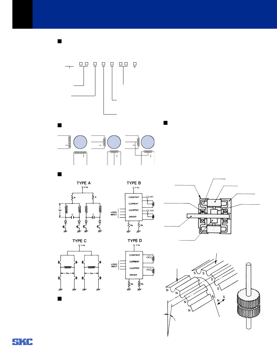
SKC Stepping Motor Part Number
1.
Stepping motor model number description - SKC’s stepping
motor model number is determined by the following:
Lead Wire Configuration and Color Guide
Typical Drive Circuits
Features of Stepping Motors
1.
Rotational speed is proportional to the frequency of input
pulses (stepping rate).
2.
Digital control of speed and position.
3.
Open loop system with no position feedback required.
4.
Excellent response to acceleration, deceleration and step
commands.
4
3
2
1
5.
Noncumulative positioning error (± 5% of step angle).
6.
Excellent low speed/high torque characteristics without
gear reduction.
7.
Inherent detent torque.
8.
Holding torque when energized.
9.
Bidirectional operation.
10. Can be stalled without motor damage.
11. No brushes for longer trouble free life.
12. Precision ball bearings.
Typical Stepping Motor Applications
For accurate positioning of X-Y tables, plotters, printers, facsimile
machines, medical applications, robotics, barcode scanners,
image scanners, copiers, etc.
Construction
There are three basic types of step motors: variable reluctance
(VR), permanent magnet (PM) and hybrid. SKC adopted the
hybrid type step motor design because it has some of the
desirable features of both the VR and PM. It has high resolution,
excellent holding and dynamic torque and can operate at high
stepping rate.
In Fig. 5-1 construction of SKC stepping motor is shown.
In Fig. 5-2 the detail of rotor construction is shown.
Fig. 5-1 Stepping Motor Construction
Fig. 5-2 Rotor Construction
5
S S T
Hybrid Type
Stepping Motor
Motor Size
(O.D. in mm)
Motor Length
O to 5
Construction –
C: Steel Housing
O: No Steel Housing
Shaft Configuration
O: Single
1: Double
Motor Characteristics (1-99)
Step Angle
C: 0.9º
D: 1.8º
G: 3.6º
H: 3.75º
BROWN (A)
ORANGE (A)
Front End Bell
Ball Bearing
Winding
Ball Bearing
Magnet
Rotor Laminations
Rotor Laminations
Half Pitch
Off Set
Magnet
Magnet
Polarity
Rotor Laminations
Rear End Bell
Stator
RED
(B)
YELL
OW
(B)
BROWN (A)
BLACK (COM A)
ORANGE (A)
RED
(B)
WHITE
(COM
B)
YELL
OW
(B)
BROWN (A)
BLACK (COM)
ORANGE (A)
RED
(B)
YELL
OW
(B)
O
P
E
RA
T
ION
& T
H
EOR
Y
STEP
MOTOR
5
STEPPING MOTORS
Stepping Motor Theory
Using a 1.8 degree, unipolar, 4-phase stepping motor as an
example, the following will explain the theory of operation.
Referring to Fig. 6-1, the number of poles on the stator is 8
spaced at 45 degree intervals. Each pole face has 5 teeth spaced
at 7.2 degree intervals. Each stator pole has a winding as shown
in Fig. 6-1.
Fig. 6-1 Stator
When applying the current to the windings in the following
sequence per Table 6-1, the stator can generate the rotating
magnetic field as shown in Fig. 6-2 (steps 1 thru 4).
Table 6-1 Step Phase Sequence (1 Phase Excited)
Step 1 Step 2
6
Fig. 6-2 Rotational Magnetic Field Generated by Phase Sequence
The hybrid rotor has 2 sets (stacks) of laminations separated by
a permanent magnet. Each set of lams has 50 teeth and are
offset from each other by
1
⁄
2
tooth pitch. This gives the rotor 50 N
and 50 S poles at the rotor O.D.
Fig. 6-3 illustrates the movement of the rotor when the phase
sequence is energized.
In step 1, phase A is excited so that the S pole of the rotor is
attracted to pole 1,5 of the stator which is now a N pole, and the
N pole of the rotor is attracted to pole 3,7 of the stator which is
a S pole now. At this point there is an angle difference between
the rotor and stator teeth of 1/4 pitch (1.8 degrees). For
instance, the stator teeth of poles 2,6 and 4,8 are offset 1.8
degrees from the rotor teeth.
In step 2, there is a stable position when a S pole of the rotor is
lined up with pole 2,6 of the stator and a N pole of the rotor lines
up with pole 4,8 of stator. The rotor has moved 1.8 degrees of
rotation from step 1.
The switching of phases per steps 3, 4 etc. produces 1.8 degrees
of rotation per step.
Fig. 6-3 1 Phase Excitation Sequence
Drive Pulse
Phase A
Step 1
ON
OFF
Step 2
Step 3
Step 4
Phase A
Phase B
Phase B
3
4
2
8
7
6
S
N
N
S
1
5
3
4
2
8
7
6
S
N
S
N
1
5
3
4
2
8
7
6
N
S
S
N
1
5
3
4
2
8
7
6
N
S
N
S
1
5
Winding
Stator Pole
Pole 1,5
Step 1
Stator
Rotor
Step 2
Stator
Rotor
Step 3
Stator
Rotor
Pole 2,6
Pole 3,7
Pole 4,8
O
P
E
RA
T
ION
& T
H
EOR
Y
STEP
MOTOR
6
STEPPING MOTORS
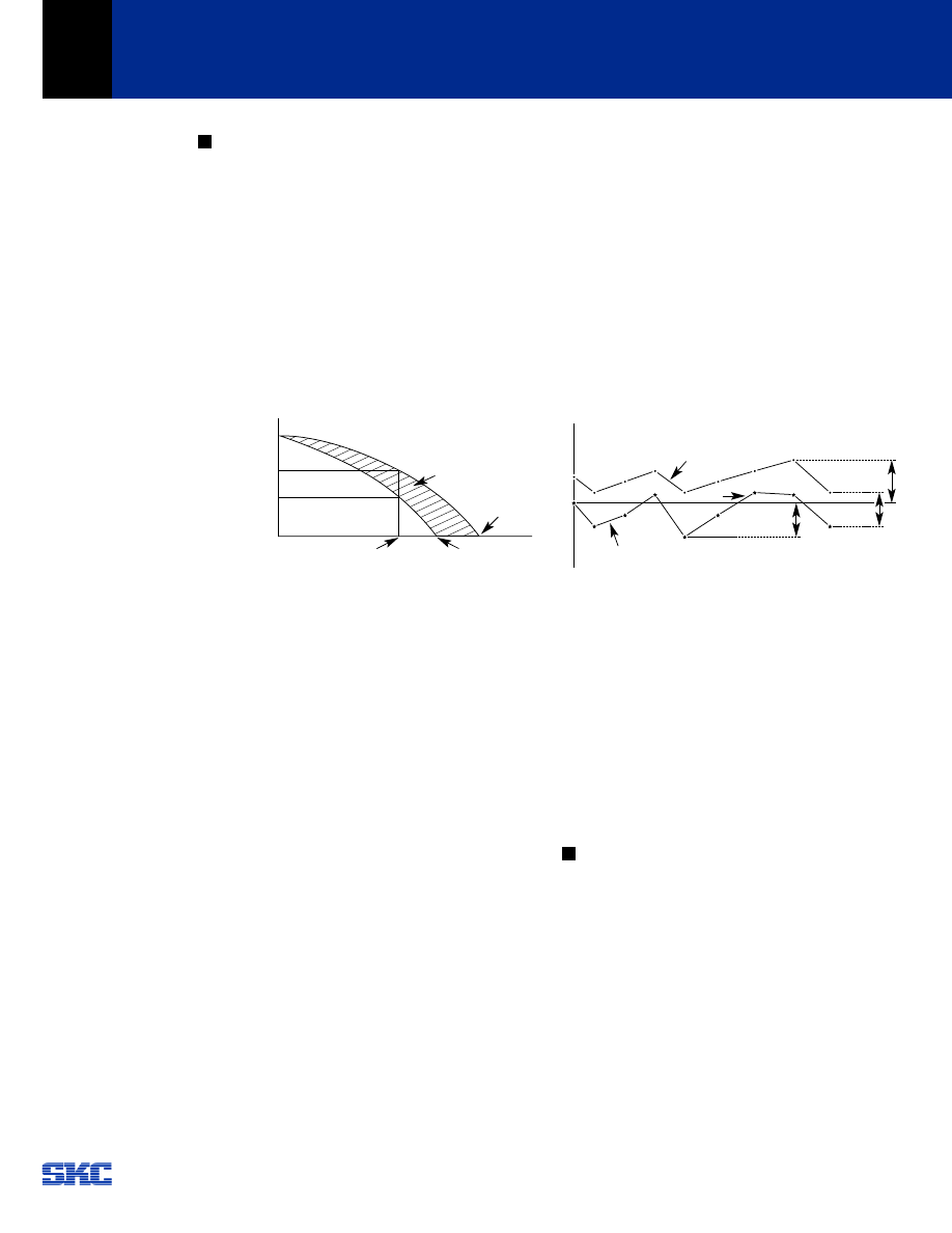
Technical Data and Terminology
7-1 Holding Torque
The maximum steady torque that can be applied to the
shaft of an energized motor without causing continuous
rotation.
7-2 Detent Torque
The maximum torque that can be applied to the shaft of a
non-energized motor without causing continuous rotation.
7-3 Speed-Torque Curve
The speed-torque characteristics of a stepping motor are a
function of the drive circuit, excitation method and load
inertia.
Fig. 7-1 Speed - Torque Curve
7-4 Maximum Slew Frequency
The maximum rate at which the step motor will run and
remain in synchronism.
7-5 Maximum Starting Frequency
The maximum pulse rate (frequency) at which an
unloaded step motor can start and run without missing
steps or stop without taking more steps than pulses.
7-6 Pull-out Torque
The maximum torque that can be applied to the shaft of a
step motor (running at constant speed) and not cause it to
lose step.
7-7 Pull-in Torque
The maximum torque at which a step motor can start, stop
and reverse the direction of rotation without losing step.
The maximum torque at which an energized step motor
will start and run in synchronism, without losing steps, at
constant speed.
7-8 Slewing Range
This is the area between the pull-in and pull-out torque
curves where a step motor can run without losing step,
when the speed is increased or decreased gradually. Motor
must be brought up to the slew range with acceleration
and deceleration technique known as ramping.
7
7-9 Start-Stop Range
This is the range where a stepping motor can start, stop
and reverse the direction of rotation without losing step.
7-10 Accuracy
This is defined as the difference between the theoretical
and actual rotor position expressed as a percentage of
the step angle. Standard is ±5%. An accuracy of ±3% is
available on special request. This positioning error is
noncumulative.
7-11 Hysteresis Error
This is the maximum accumulated error from theoretical
position for both forward and backward direction of
rotation. See Fig 7-2.
Fig. 7-2 Step Angle Accuracy
7-12 Resonance
A step motor operates on a series of input pulses, each
pulse causing the rotor to advance one step. In this time
the motor’s rotor must accelerate and then decelerate to a
stop. This causes ringing, overshoot and vibration. There
are some speeds at which the motor will not run. This is
called its resonant frequency. The objective is to design the
system so that no resonant frequencies appear in the
operating speed range. This problem can be eliminated by
means of using mechanical dampers or external
electronics.
Drive Methods
8-1 Drive Circuits
The operation of a step motor is dependent upon an
indexer (pulse source) and driver. The indexer feeds pulses
to the driver which applies power to the appropriate motor
windings. The number and rate of pulses determines the
speed, direction of rotation and the amount of rotation of
the motor output shaft. The selection of the proper driver
is critical to the optimum performance of a step motor. Fig.
8-1 shows some typical drive circuits.
These circuits also illustrate some of the methods used to
protect the power switches against reverse voltage
transients.
8
Holding Torque
Dynamic Torque
(Resonance point is not included herein.)
Driving Frequency
(Speed)
Max. No Load
Response (PPS)
Max. Response
(PPS)
Backward
Start-Stop Range
Pull-out Torque
Torque
(kgf-
cm)
Angle
Error
Pull-in Torque
Forward
Theoretical
Angle
Neg. Max. Error
Positive Max.
Error
Slew Range
Hysteresis
O
P
E
RA
T
ION
& T
H
EOR
Y
STEP
MOTOR
7
STEPPING MOTORS
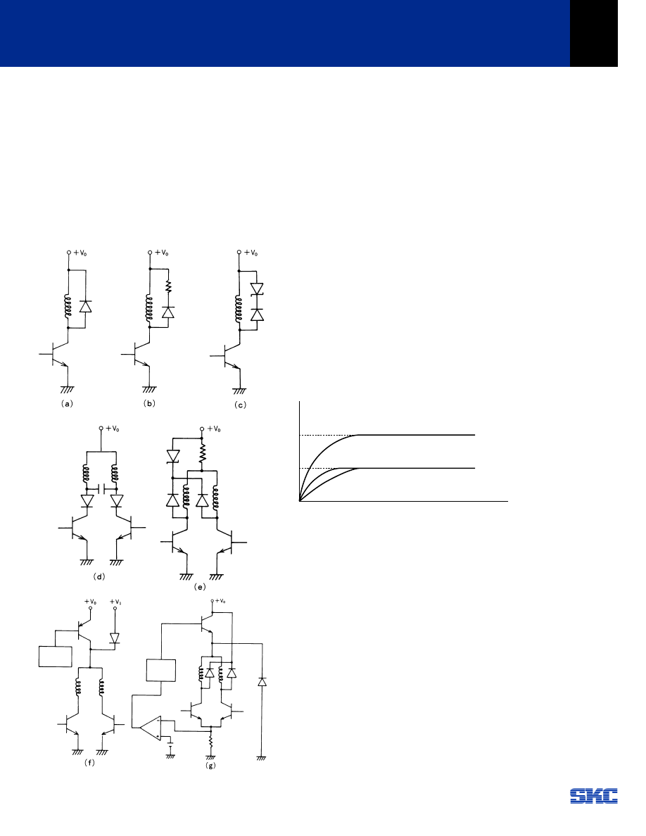
8-1-1 Damping Methods
These circuits can also be used to improve the damping
and noise characteristics of a step motor. However, the
torque at higher pulse rates (frequency) can be reduced so
careful consideration must be exercised when selecting one
of these methods.
Examples:
1.
Diode Method
Fig. 8-1 (a)
2.
Diode + Resistance Method
Fig. 8-1 (b)
3.
Diode + Zener Diode Method
Fig. 8-1 (c )
4.
Capacitor Method
Fig. 8-1 (d)
Fig. 8-1
8-1-2 Stepping Rate
A step motor operated at a fixed voltage has a decreasing
torque curve as the frequency or step rate increases. This
is due to the rise time of the motor winding which limits the
value of the coil current. This is determined by the ratio of
inductance to resistance (L/R) of the motor and driver as
illustrated in Fig 8-2 (a).
Compensation for the L/R of a circuit can be accomplished
as follows:
a)
Increase the supply voltage and add a series resistor,
Fig 8-2 (b), to maintain rated motor current and
reduce the L/R of the circuit.
b)
Increase the supply voltage, Fig 8-2 (c), improving
the time constant (L/R) of the circuit. However, it is
necessary to limit the motor current with a bi-level or
chopped supply voltage.
Examples:
1.
Constant Voltage Drive
Fig. 8-1 (e)
2.
Dual Voltage (Bi-level) Drive
Fig. 8-1 (f)
3.
Chopper Drive
Fig. 8-1 (g)
Fig. 8-2
Note:
τ
= Electrical Time Constant
(c) :
τ
= L/R
Supply Voltage = 2 V
0
(b) :
τ
= L/2R
Supply Voltage = 2 V
0
(a) :
τ
= L/R
Supply Voltage = V
0
(a)
(b)
(c)
2 I
0
I
0
Current
O
P
E
RA
T
ION
& T
H
EOR
Y
STEP
MOTOR
8
STEPPING MOTORS
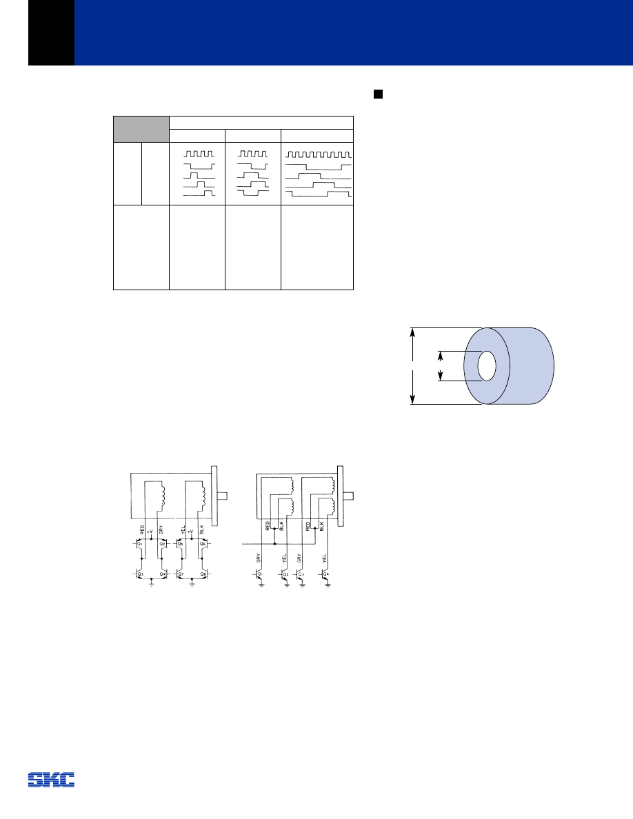
8-2 Excitation Methods
In Table 8-1 are descriptions and features of each method.
Table 8-1
8-3 Bipolar and Unipolar Operation
All SKC stepper motors are available with either two coil
bipolar or four coil unipolar windings.
Bipolar Winding - the stator flux is reversed by reversing
the current in the winding. It requires a push-pull bipolar
drive as shown in Fig. 8-3. Care must be taken to design
the circuit so that the transistors in series do not short the
power supply by coming on at the same time. Properly
operated, the bipolar winding gives the optimum
performance at low to medium step rates.
Fig. 8-3 Bipolar Method Fig. 8-4 Unipolar Method
Unipolar Winding - has two coils wound on the same
bobbin per stator half. Flux is reversed by energizing one
coil or the other coil from a single power supply. The use
of a unipolar winding, sometimes called a bifilar winding,
allows the drive circuit to be simplified. Not only are one-
half as many power switches required (4 vs. 8), but the
timing is not as critical to prevent a current short through
two transistors as is possible with a bipolar drive. Unipolar
motors have approximately 30% less torque at low step
rates. However, at higher rates the torque outputs are
equivalent.
Step Motor Load Calculations and Selection
To select the proper step motor, the following must be
determined:
1.
Load Conditions
1-a. Friction Load
1-b. Load Inertia
2.
Dynamic Load Conditions
2-a. Drive Circuit
2-b. Maximum Speed (PPS/Frequency)
2-c. Acceleration/Deceleration Pattern
With the above load information the proper step
motor can be selected.
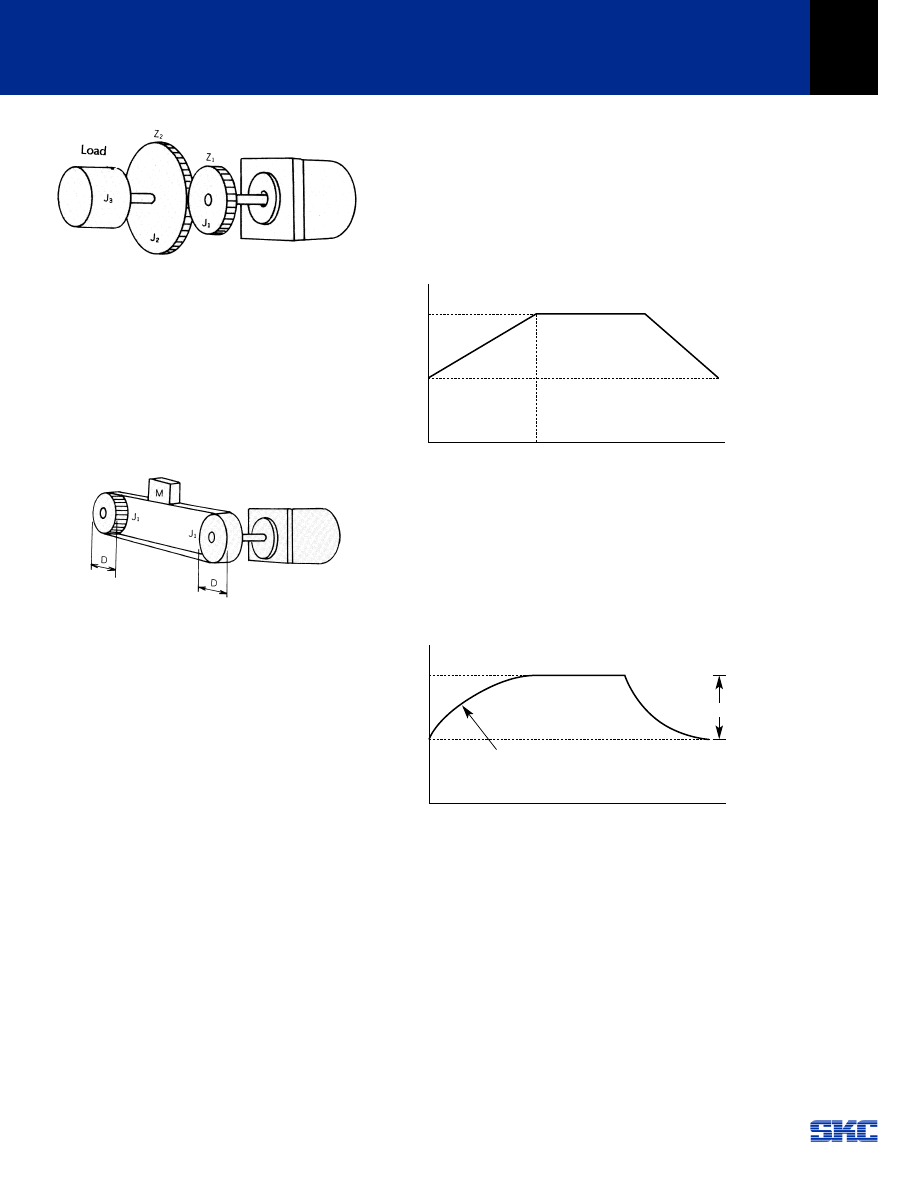
9-1 Load Inertia
The following is an example for calculating the inertia of a
hollow cylinder.
Fig. 9-1
J =
1
⁄
8
. M . (D
1
2
+ D
2
2
) (kg-cm
2
)
Where
M: mass of pulley (kg)
D
1
: outside diameter (cm)
D
2
: inside diameter (cm)
9-2 Linear systems can be related to rotational systems by
utilizing the kinetic energy equations for the two systems.
For linear translations:
Energy =
1
⁄
2
M v
2
=
1
⁄
2
J w
2
Where
M: mass
v:
velocity
J:
inertia
w:
angular velocity
1)
Gear drive system
When gears are used to drive a load, the inertia reflected
to the motor is expressed by the following equation:
J = (Z
1
/Z
2
)
2
. (J
2
+ J
3
) + J
1
Where
Z
1
, Z
2
:
No. of gear teeth
J
1
, J
2
, J
3
:
inertia (kg-cm
2
)
J:
reflected inertia, (kg-cm
2
)
9
Excitation Method
Single Phase
Switching
sequence
Features
Pulse
phase A
phase B
phase A
phase B
Hold & running
torque reduced
by 39%
Increased efficiency.
Poor step accuracy.
High torque
Good step accuracy.
Poor step accuracy.
Good resonance
characteristics.
Higher pulse rates.
Half stepping
Dual Phase
1-2 Phase
D
1
D
2
O
P
E
RA
T
ION
& T
H
EOR
Y
STEP
MOTOR
9
STEPPING MOTORS
Fig. 9-2
2)
Pulley & belt system. A motor and belt drive arrangement
is used for linear load translation
J = 2 J
1
+
1
⁄
4
M D
2
Where
J:
Total inertia reflected to motor
J
1
:
inertia of pulley (kg-cm
2
)
D:
diameter of pulley (cm
2
)
M: weight of load (kg)
Fig. 9-3
9-3 Determination of load acceleration/deceleration pattern.
9-3-1Load Calculation
To determine the torque required to drive the load
the following equation should be satisfied.
T
m
= T
f
+ T
j
Where:
T
m
: Pullout torque (kgf-cm)
T
f
:
Friction torque (kgf-cm)
T
j
:
Inertia load (kgf-cm)
T
J
= (J
R
+ J
L
)/g . (
π
.
θ
. s)/180 . df/dt
J
R
:
Rotor inertia [kg-cm
2
]
J
L
:
Load inertia [kg-cm
2
]
θ
:
Step angle [deg]
g:
Gravity acceleration = 980 [cm/sec
2
]
f:
Drive frequency [PPS]
Example: A 1.8 degree step motor is to be accelerated from 100 to
1,000 pulses per second (PPS) in 50 ms, J
R
= 100 g-cm
2
, J
1
= 1 kg-cm
2
.
The necessary pullout torque is:
T
J
= (0.1 + 1)/980 . (
π
. 1.8)/180 . (1000 - 100)/0.05
= 0.635 (kgf-cm)
9-3-2 Linear acceleration
For linear acceleration as shown in Fig. 9-4
frequency f(t), inertial system frequency f
j
(t) and
inertia load T
j
are expressed as follows:
f(t) = (f
1
- f
0
)/t
1
. t + f
0
T
J
= (J
R
+ J
L
)/g . (
π
.
θ
. s)/180 . (f
1
- f
0
)/t
1
Fig. 9-4 Linear Acceleration
9-3-3Exponential acceleration
For exponential as shown in Fig. 9-5, drive frequency
f(t) and inertia load T
j
are expressed as follows:
f(t) = f
1
. (1 - e^-(t/
τ
)) + f
0
T
J
= (J
R
+ J
L
)/g . (
π
.
θ
. s)/180 . f
1
/
τ
. e^-(t/
τ
)
Fig. 9-5 Exponential Acceleration
t
1
Time
f
0
f
1
Time
Exponential of
f
0
f
1
H
OL
DI
NG
T
OR
QU
E
STEP
MOTOR
10
STEPPING MOTORS
SST-39C1
SST-40C1
SST-40C2
SST-39D1
SST-39D2
SST-42D1
SST-42D2
SST-55D1
SST-55D2
SST-55D3
SST-55D4
SST-55D5
STH-56D1
STH-56D2
STH-56D3
SST-57D1 / SST-58D1
SST-57D2 / SST-58D2
SST-57D3 / SS
SST-
SLC-42H1
step angle
(deg)
0.9
1.8
3.75
STEP MOTOR
100
200
5
10
1
H
OL
DI
NG
T
OR
QU
E
STEP
MOTOR
11
STEPPING MOTORS
ST-58D3
-57D4 / SST-58D4
SST-57D5 / SST-58D5
SST-83D1
SST-83D2
SST-83D3
HOLDING TORQUE RANGE
300
500
600
700
oz-in
5
20
40
50
kgf-cm
Wyszukiwarka
Podobne podstrony:
Katalog silników krokowych Minebea
Minebea katalog silników krokowych
Opis silnikow krokowych id 3370 Nieznany
Kontroler silnika krokowego na porcie LPT3
Kontroler silnika krokowego na porcie LPT2
3 Silnik krokowy
badanie silnika krokowego, mechanika, BIEM- POMOCE, automatyka i sterowanie
Kontroler silnika krokowego na porcie LPT6
silniki krokowe
Instrukcja R4 Silnik krokowy
SILNIKI KROKOWE
Astra F Silnik krokowy w X16SZR
Najprostszy sterownik silników krokowych, ELEKTRONIKA
4 emulacja, silnik krokowy
3 Silnik krokowy
silniki krokowe
więcej podobnych podstron