taligentx.com: Passat - Door Lock Mechanism Repair
www.taligentx.com - Collections Friday, December 16, 2005
photos
passat
music server
http://www.taligentx.com/passat/maintenance/doorlockmechanism/ (1 of 14)16/12/2005 17:43:42
taligentx.com: Passat - Door Lock Mechanism Repair
http://www.taligentx.com/passat/maintenance/doorlockmechanism/ (2 of 14)16/12/2005 17:43:42
taligentx.com: Passat - Door Lock Mechanism Repair
home
|
passat
|
maintenance & repair
|Door Lock Mechanism Repair
Door Lock Mechanism Repair
Symptoms:
Door(s) fail to respond normally to lock/unlock signals. In several cases, sending a lock signal via
remote locks all but one door. Subsequently sending an unlock and second lock signal then locks the
problematic door. Also, when the door in question is the driver's side front door with an aftermarket
window controller (
AlienTech
, etc), the controller usually fails to operate as usual.
Problem:
The door locking mechanism - responsible for coordinating the activities of the handles, key, and alarm -
is having an electronic malfunction, most likely a cracked solder joint from repeated door opening/
closing. This is combined with a poor design layout that stresses internal solder joints if the locking
mechanism screws loosen and allows movement of the entire unit in the door.
This, of course, is assuming that the door locks and unlocks mechanically without problem (through the
interior handle, exterior handle, and key insertion).
Replacing the part with a new one will be a definite fix, but you may also want to consider popping the
unit open and look for any obvious problems - despite appearances the internal parts susceptible to
failure are simple to troubleshoot and repair.
Also, considering that you'll be removing the inner door panel to access the locking mechanism, now
would be a good time to add some noise dampening material to the metal door skin if you desire. There
is a damping panel in place from the factory, and it would be interesting to hear if adding additional
material would have a noticeable effect.
http://www.taligentx.com/passat/maintenance/doorlockmechanism/ (3 of 14)16/12/2005 17:43:42

taligentx.com: Passat - Door Lock Mechanism Repair
(katrina relief ads)
Part Information & Sources:
Note - always confirm part numbers by looking at the actual part mounted in the car! Mistakes will
happen sometime, somewhere.
Part numbers:
'98-01
Driver's front door lock module
pre VIN 3B-X-090000
post VIN 3B-X-090001
3B1 837 015 E
3B1 837 015 J
Passenger's front door lock module
pre VIN 3B-X-090000
post VIN 3B-X-090001
3B1 837 016 D
3B1 837 016 R
'01.5-05
Driver's front door lock module
3B1 837 015 AK
Passenger's front door lock module 3B1 837 016 BH
OEM Pricing: ~$105-$130
Specialized German Recycling
: $45
Austin VeeDub
: $65
Tools:
●
Socket wrench
●
10mm socket
●
Torx drivers/bits: T10*, T20, T25
●
12 point star driver/bit (aka triple-square or spline bit): M8
●
Soldering iron*
●
Solder* (try Kester! Good stuff.)
●
Desoldering braid*
●
Multimeter*
*Only needed if disassembling the locking mechanism.
Autozone carries a good variety of bits, more so than the other chains I've tried (O'Reilly's, PepBoys,
http://www.taligentx.com/passat/maintenance/doorlockmechanism/ (4 of 14)16/12/2005 17:43:42

taligentx.com: Passat - Door Lock Mechanism Repair
Sears Hardware). You should be able to find the triple square bit in a multipack - buy it, the pack is
useful for other work on the car. While you're there, also pick up the large hex driver set - it even
includes a 17mm hex driver for removing the auto transmission drain plug. No other store carried the
item or had any idea where to obtain it.
Time Required: 1.5-3 hours, depending on individual pace.
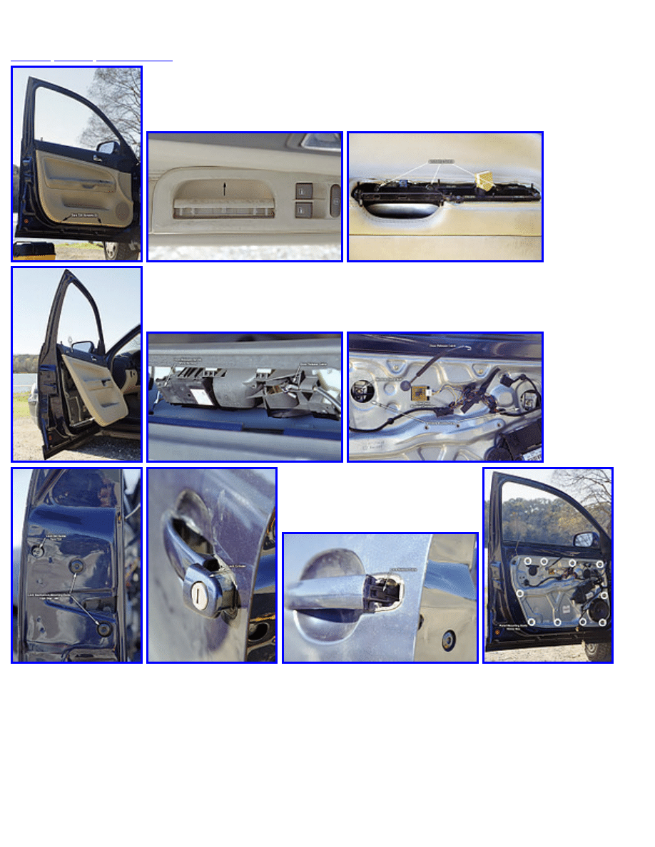
Locking Mechanism Removal:
Start by removing the door trim panel.
1. Begin by lowering the door window glass completely.
2. There are two black Torx T25 screws at the bottom of the door - remove them.
(illustration)
3. Use a thin-bladed flathead screwdriver to pry off the inner door handle cover (not the door
release handle).
(illustration)
4. For the driver side door, you can now pull up on the entire handle/switch assembly as a unit - use
moderate force to unclasp the clips holding it in place. Remove the brown wire harness from the
handle/switch assembly and set the assembly aside.
5. For the drivers side door, there are three bronze color screws anchoring the door trim panel to the
rest of the door. The passenger's side door has two of these screws. Use a large philips-head
screwdriver to remove these.
(illustration)
6. The rest of the door trim panel is now held in place by snap-in anchors and can be loosened by
pulling the trim panel away from the door. Begin with the bottom of the door and give it a good
tug to pop out the connectors. Take care not to pull the trim panel far away from the door, as
there are several wire/cable connections still in place between the trim panel and door. After the
lower portion of the trim panel is separated, pull the entire panel upward to unhinge the panel
from the window sill. The trim panel should now be free from the door, with several wires and
cables still in place.
(illustration)
7. Disconnect the following from the trim panel:
(illustration)
a. Wire harness plugged into the door release handle.
b. Door release cable. To remove this, pull the cable insulation away from the hooked end
and slide the exposed cable out of the slitted retainer. Release the hooked end.
c. Security alarm LED wire connector.
d. Bottom door sill lamp - it's easier to pull out the entire wire harness + lamp assembly than
to disconnect the wire harness.
8. Pull the door trim panel away and set aside.
Next, window glass removal:
9. Remove the two large, circular rubber inserts from the metal door panel. If you pry with a
screwdriver, take care not to damage the mating surfaces.
(illustration)
10. Reconnect the handle/switch assembly to the brown wire harness to allow window control. With
http://www.taligentx.com/passat/maintenance/doorlockmechanism/ (5 of 14)16/12/2005 17:43:42

taligentx.com: Passat - Door Lock Mechanism Repair
the key in the On position (no need to start the engine), roll up the window until the window
clamp screws are accessible through the circular cutouts.
11. Use a 10mm socket to loosen the clamps holding the window glass in place - it will only take a
few turns to loosen the clamps, no need to remove the screws entirely.
12. Roll the window down until a third of the window glass is left visible in the window frame.
13. Disconnect the handle/switch assembly.
14. Remove the window glass. Reach over the top of the door and pull the window glass upwards
(towards yourself). As you raise the window glass, angle it towards the hinge side of the door to
allow the window glass to clear the window slot. Set the window glass aside.
Unhooking the lock mechanism:
15. On the end side of the door, pry off the black plastic cap above the lock mechanism screws. This
cap covers the access hole for the lock set screw.
(illustration)
16. Use a Torx T20 driver to unscrew the set screw. Unscrew it as far as it will go, then reinsert a few
threads to keep the screw from falling out of its mounting.
17. Pull on the exterior door handle - with the door handle in this position, pull on the lock cylinder.
It should slide out without much trouble. Set the lock cylinder aside.
(illustration)
18. There is a cable hooked into the side of the exterior door handle. The cable can be positioned at
various points along the handle. Note the current position of the cable and release it from the
handle.
(illustration)
19. Use the M8 12 point star driver to remove the two screws in the door side. On my car, these
screws were loose and allowed the lock mechanism to move around, causing solder joint stress -
keep reading...
(illustration)
Removing the metal panel:
20. Disconnect the various wire harnesses on the metal door panel - don't worry about what goes
where - each connector can only fit in one and only one place. Also use a flathead screwdriver to
unclip the various snaps holding the wiring to the panel.
21. Use the 10mm socket to unscrew the ten hex bolts securing the metal panel to the door frame.
(illustration)
22. Pull the panel away from the door frame starting at the edges - if you haven't removed the panel
before, the gasket may require a bit of force to pry it away from the frame. Carefully maneuver
the entire panel around until the panel is free of the door frame with the lock mechanism and
associated wiring attached.
(illustration)
23. Remove the wire harness from the lock mechanism and remove it from the metal panel - this will
allow you to completely separate the metal panel from the door.
(illustration)
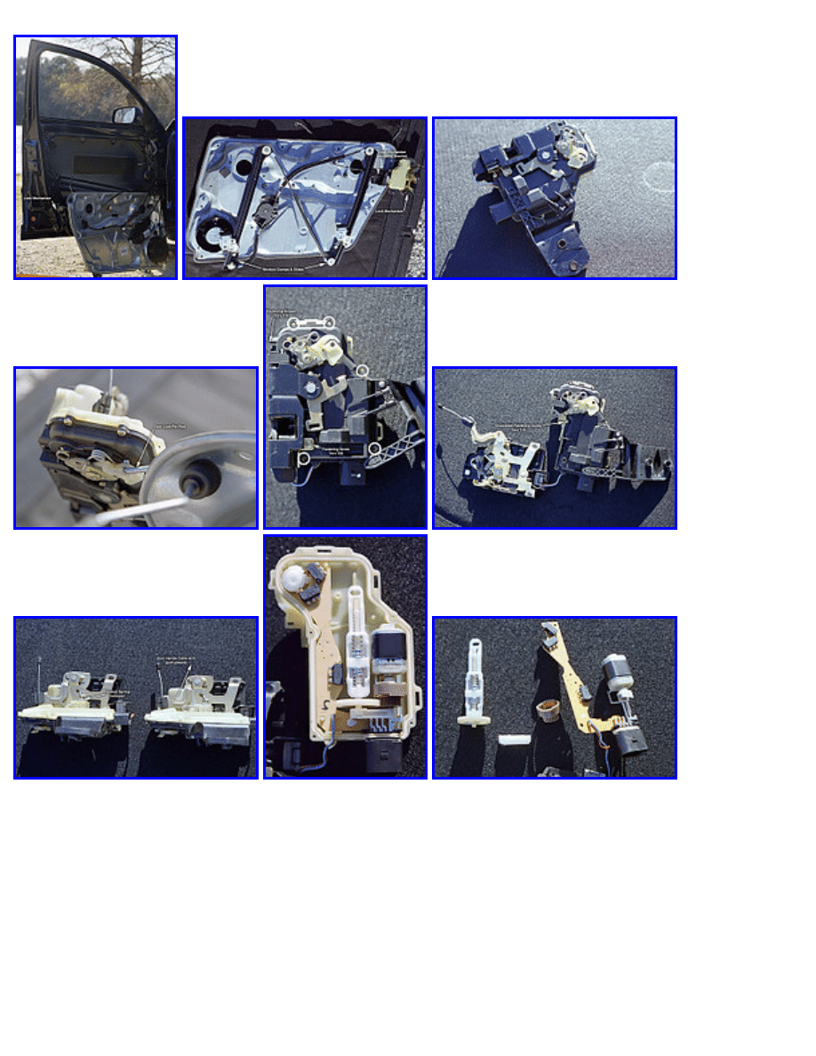
Removing the lock mechanism:
http://www.taligentx.com/passat/maintenance/doorlockmechanism/ (6 of 14)16/12/2005 17:43:42

taligentx.com: Passat - Door Lock Mechanism Repair
24. The lock mechanism is held in place on the metal panel by a plastic bracket with two cylindrical
pins keeping the bracket in place. Use a blunt tool to push the pins out from the rear of the panel.
My Passat had managed to work the pins loose and dropped them into the door frame, where
they've likely lain for months. The bracket had then worked loose of the panel and the entire lock
mechanism was free to jostle around in the door. The wiring harness, still being pinned in place,
then stressed the electrical connectors internal to the lock mechanism and cracked a solder joint.
25. Unhook the door lock pin rod from the lock mechanism.
(illustration)
26. Remove the interior door release handle cable. Start by popping the harness out of the mount on
the locking mechanism, then unhook the cable.
27. Separate the locking mechanism from the panel.
(illustration)
If you are simply replacing the entire mechanism, pop on the replacement and retrace your steps. If
you're feeling charitable,
contact me
- I'd like to take a look at other failed units and see if the problem
with mine is common, or if Passat owners can expect a variety of failure modes. If you'd like to attempt
repair, read on.
The trouble area of the mechanism is in the electrical connection part of the unit. This is the black &
pale yellow plastic section held together by a total of 8 screws and two plastic snaps.
Locking Mechanism Disassembly:
1. Use a Torx T10 driver to unscrew the 5 visible Torx screws (four on the face, one on the side).
(illustration)
2. Pull the plastic bracket's long clip from the mechanism - there is a sixth screw hidden underneath.
3. Use a Torx T20 to remove the large Torx screw.
4. You should now be able to carefully pull apart the two sections of the mechanism - you'll need to
unclip the plastic snaps while pulling the sections away from each other.
(illustration)
5. After pulling these sections away, the last Torx T10 screw will be revealed. Remove it.
6. Flip the mechanism to the yellow plastic side. Pull and remove the spring indicated.
(illustration)
7. Pull the metal handle indicated upward to allow separation of the two halves.
8. Flip to the black plastic side without allowing the two halves to separate.
9. The internals of the mechanism are mounted on the yellow plastic half - carefully pull up on the
black plastic half to reveal the electronics inside.
(illustration)
Locking Mechanism Diagnosis:
The electronics are straightforward. Two microswitches at the top of the unit detect if the key is moving
the lock cylinder to the lock or unlock positions. The microswitch next to the white plastic slide
determines the current state of the door lock. The motor actuates electronic locking and unlocking.
Note: Take care not to change the position of the various handles and slides - it's fairly easy to determine
http://www.taligentx.com/passat/maintenance/doorlockmechanism/ (7 of 14)16/12/2005 17:43:42

taligentx.com: Passat - Door Lock Mechanism Repair
how the different switches and handles interact with each other when it's time to put things back
together, but it's easier to leave everything in the positions discovered. Also, note the position of the
brown gear on the motor shaft to the small white attachment mounted inside. There is an alignment
between the notch in the copper track inside the brown gear and a metal cylinder in the white plastic
container. Just be sure to reset this relationship during reassembly.
10. Pull the white slide from the assembly, along with the white mount holding the shaft of the
plastic slide screw and the motor shaft in place. Set aside, without changing the state of the
plastic slide and screw.
(illustration)
11. Pull the circuit board and motor from the yellow plastic half and flip upside down.
(illustration)
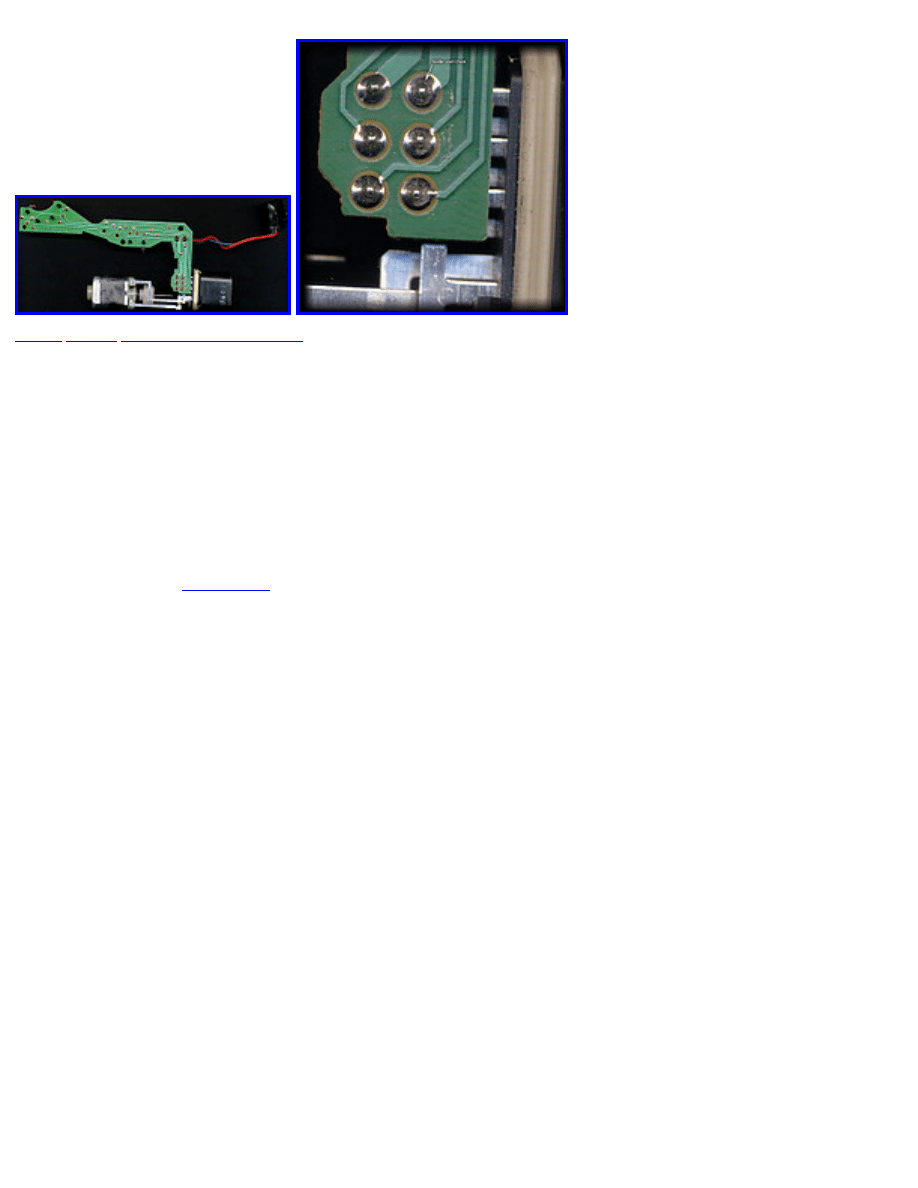
Troubleshooting:
12. Start by examining the solder joints where the wire harness connectors meet the printed circuit
board (PCB). I had a cracked joint at pin 7.
(illustration)
13. Move on and visually inspect the solder joints for the three microswitches.
14. Use a multimeter and test each of the microswitches at the solder joints for correct operation.
Usually, only two of the three contacts are used - when the switch is depressed, the two used
contacts should have 0 or near 0 resistance (or if your multimeter has continuity checking, it
should give a tone). Though usually only the trunk microswitch has a tendency to go bad, this
could have occurred here as well. If a switch is bad, you'll need to replace it - there should be a
part number somewhere for the switch, if all else fails you can always order a trunk microswitch
and mount that.
15. If the switches are good, it's probably a solder joint problem. Heat up the soldering iron and use
the desoldering braid to remove all of the solder from every joint in use on the board. Work in
sections - remove solder from a few pins, and then resolder the same connections. Removing
solder from all of the joints at once from a component will cause it to fall off the board and leave
you to realign it. Not difficult, but easy to avoid anyway.
16. The red and blue wires connecting to the other section of the unit are used for a fourth
microswitch - it isn't necessary to remove the microswitch from its mounting clip, but do test it as
with the others.
Hopefully you've just done something that fixed the problem. Reassemble in the reverse order and see if
your door (and wallet) is happy!
Comments:
●
- Dec 13, 2005 @ 3:58 pm
●
My symptoms are that the doors will "re-lock" if only the driver's door is opened and
occaisionally, the interior lights will come on while driving and the "door ajar" chime will sound.
I figure this means that the micro switch that detects if the door is ajar is malfunctioning, so I will
http://www.taligentx.com/passat/maintenance/doorlockmechanism/ (8 of 14)16/12/2005 17:43:42
Document Outline
- taligentx.com
Wyszukiwarka
Podobne podstrony:
Instrukcja obslugi VW PASSAT B5 PL up by dunaj2
BentleyPublishers com VW Passat B5 Front Bumper Removal
instrukcja wymiany tarcz i klocków hamulcowych vw Golf 4 vw passat b5 i inne Copy
vw passat B5 poduszka powietrzna
Instrukcja obslugi VW PASSAT B5 PL up by dunaj2
VW Passat B5 Kodowanie pilota
VW Passat B5 Long Life Service
Vw Passat b5 5 Service Light Reset Proceedure
vw passat B5 temperatura silnika
Vw Passat b5 b5 5 Remote Key Registration Procedure
VW Passat B5 3B Główna skrzynka bezpieczników
BentleyPublishers com VW Passat B5 Technical Brake Data
VW Passat B5 Replacing Foglight Bulbs
Volkswagen Passat B5 FL Konserwacja mechanizmu wycieraczek poradnik
PassatWorld com VW Passat B5 1 8T Waterpump Thermostat Replacement DIY
vw passat B5 zla praca silnika
Door lock repair
więcej podobnych podstron