
Power Electronics & Clean Power Research Laboratory
Power Electronics & Clean Power Research Laboratory
http://enjeti.tamu.edu
http://enjeti.tamu.edu
1 1
Texas A&M University
Texas A&M University
http://www.tamu.edu
http://www.tamu.edu
Development of High Frequency
Development of High Frequency
Link Direct DC to AC Converters for
Link Direct DC to AC Converters for
Solid Oxide Fuel Cells (SOFC)
Solid Oxide Fuel Cells (SOFC)
Dr. Prasad Enjeti
Dr. Prasad Enjeti
Power Electronics Laboratory
Power Electronics Laboratory
Department of Electrical Engineering
Department of Electrical Engineering
Texas A&M University
Texas A&M University
College Station, TX
College Station, TX
-
-
77843
77843
SECA Industrial Partner: Delphi
SECA Industrial Partner: Delphi
-
-
Auto
Auto
Power Electronics & Clean Power Research Laboratory
Power Electronics & Clean Power Research Laboratory
http://enjeti.tamu.edu
http://enjeti.tamu.edu
Texas A&M University
Texas A&M University
http://www.tamu.edu
http://www.tamu.edu
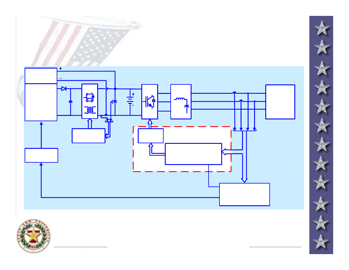
Fuel Cell Power Conditioning Stage:
Fuel Cell Power Conditioning Stage:
Block diagram
Block diagram
(dedicated loads)
(dedicated loads)
V
dc
Output Pow er
Calculator &
Ref. Generator
FUEL
CELL
STACK
ACCESSORY
LOADS
_
Gate Drive
DC/DC Control
Fuel Cell
Controller
Hydrogen
Input
PWM
I
a
I
b
V
a
V
b
I
dc
DC-DC
DC-AC
120V/240V
60Hz
Load
a
n
b
Output
Filter LC
DC-AC
Battery
DC-AC
Control Block
For Voltage & Current
Power Electronics & Clean Power Research Laboratory
Power Electronics & Clean Power Research Laboratory
http://enjeti.tamu.edu
http://enjeti.tamu.edu
Texas A&M University
Texas A&M University
http://www.tamu.edu
http://www.tamu.edu
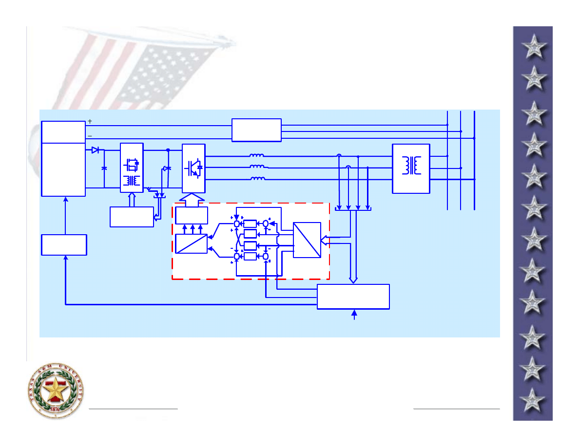
Fuel Cell Power Conditioning Stage:
Fuel Cell Power Conditioning Stage:
Block diagram
Block diagram
(connected to utility)
(connected to utility)
C
Electric Utility
L
s
L
s
L
s
V
dc
Reference Signal
Generator
P*
ref
FUEL
CELL
STACK
ACCESSORY
LOADS
_
Gate Drive
DC/DC Control
Fuel Cell
Control
Hydrogen
Input
abc
dq
I
d
I
q
*
I
d
*
PI
V
q
PI
w L
s
V
d
V*
d
V*
q
I
q
w L
s
abc
dq
SVPWM
PI
I
a
I
b
A
V
a
V
b
I
dc
B
DC-DC
DC-AC
Start-up Pow er
Controller
Transformer

Power Electronics & Clean Power Research Laboratory
Power Electronics & Clean Power Research Laboratory
http://enjeti.tamu.edu
http://enjeti.tamu.edu
Texas A&M University
Texas A&M University
http://www.tamu.edu
http://www.tamu.edu
High Frequency Link Direct DC to AC
High Frequency Link Direct DC to AC
Converters for SOFC
Converters for SOFC
This project proposes to design and develop high
This project proposes to design and develop high
frequency link direct DC to AC converters to improve
frequency link direct DC to AC converters to improve
performance, optimize the size, cost, weight and
performance, optimize the size, cost, weight and
volume of the DC to AC converter in SOFC systems
volume of the DC to AC converter in SOFC systems
The proposed topologies employ a high frequency
The proposed topologies employ a high frequency
link, direct DC to AC conversion approach. The direct
link, direct DC to AC conversion approach. The direct
DC to AC conversion approach operates without an
DC to AC conversion approach operates without an
intermediate dc
intermediate dc
-
-
link stage
link stage
The absence of the dc
The absence of the dc
-
-
link, results in the elimination
link, results in the elimination
of bulky, aluminum electrolytic capacitors, which
of bulky, aluminum electrolytic capacitors, which
could result in lower weight/volume/size and cost of
could result in lower weight/volume/size and cost of
the power electronic converter
the power electronic converter

Power Electronics & Clean Power Research Laboratory
Power Electronics & Clean Power Research Laboratory
http://enjeti.tamu.edu
http://enjeti.tamu.edu
Texas A&M University
Texas A&M University
http://www.tamu.edu
http://www.tamu.edu
R&D Objectives & Approach
R&D Objectives & Approach
The primary objective is to realize cost effective fuel
The primary objective is to realize cost effective fuel
cell converter, which operates under a wide input
cell converter, which operates under a wide input
voltage range, and output load swings with high
voltage range, and output load swings with high
efficiency and improved reliability
efficiency and improved reliability
Employ state of the art power electronic devices &
Employ state of the art power electronic devices &
configure two unique topologies to achieve direct
configure two unique topologies to achieve direct
conversion of DC power (24
conversion of DC power (24
-
-
48V) available from a
48V) available from a
SOFC to AC power (120/240V, 60Hz) suitable for
SOFC to AC power (120/240V, 60Hz) suitable for
utility interface and powering stand alone loads
utility interface and powering stand alone loads
Investigate direct DC to AC conversion
Investigate direct DC to AC conversion
Power Electronics & Clean Power Research Laboratory
Power Electronics & Clean Power Research Laboratory
http://enjeti.tamu.edu
http://enjeti.tamu.edu
Texas A&M University
Texas A&M University
http://www.tamu.edu
http://www.tamu.edu
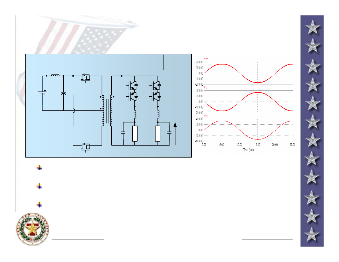
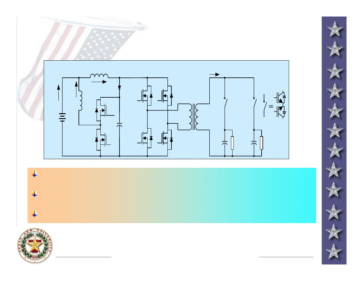
Voltage
Voltage
-
-
fed High Frequency Link
fed High Frequency Link
Direct DC to AC Converters for SOFC
Direct DC to AC Converters for SOFC
S
1
S
2
T
a
T
b
Direct DC-AC Converter with
High Freqency Link Transformer
120 V
60 Hz
V
dc
a
c
b
(n)
L
O
A
D
L
O
A
D
I
dc
t
V
t
+
-
I
a
I
b
Input
Filter
I
Direct DC to AC power conversion of fuel cell voltage (22V) to
Direct DC to AC power conversion of fuel cell voltage (22V) to
120/240V AC, 60Hz
120/240V AC, 60Hz
The switches are operated in high frequency (40kHz), zero curren
The switches are operated in high frequency (40kHz), zero curren
t
t
switching (ZCS) mode
switching (ZCS) mode
ZCS also guarantees transformer volt
ZCS also guarantees transformer volt
-
-
second balance
second balance
Power Electronics & Clean Power Research Laboratory
Power Electronics & Clean Power Research Laboratory
http://enjeti.tamu.edu
http://enjeti.tamu.edu
Texas A&M University
Texas A&M University
http://www.tamu.edu
http://www.tamu.edu
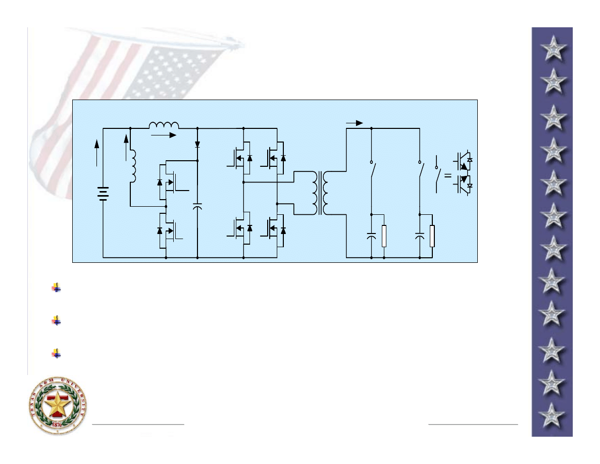
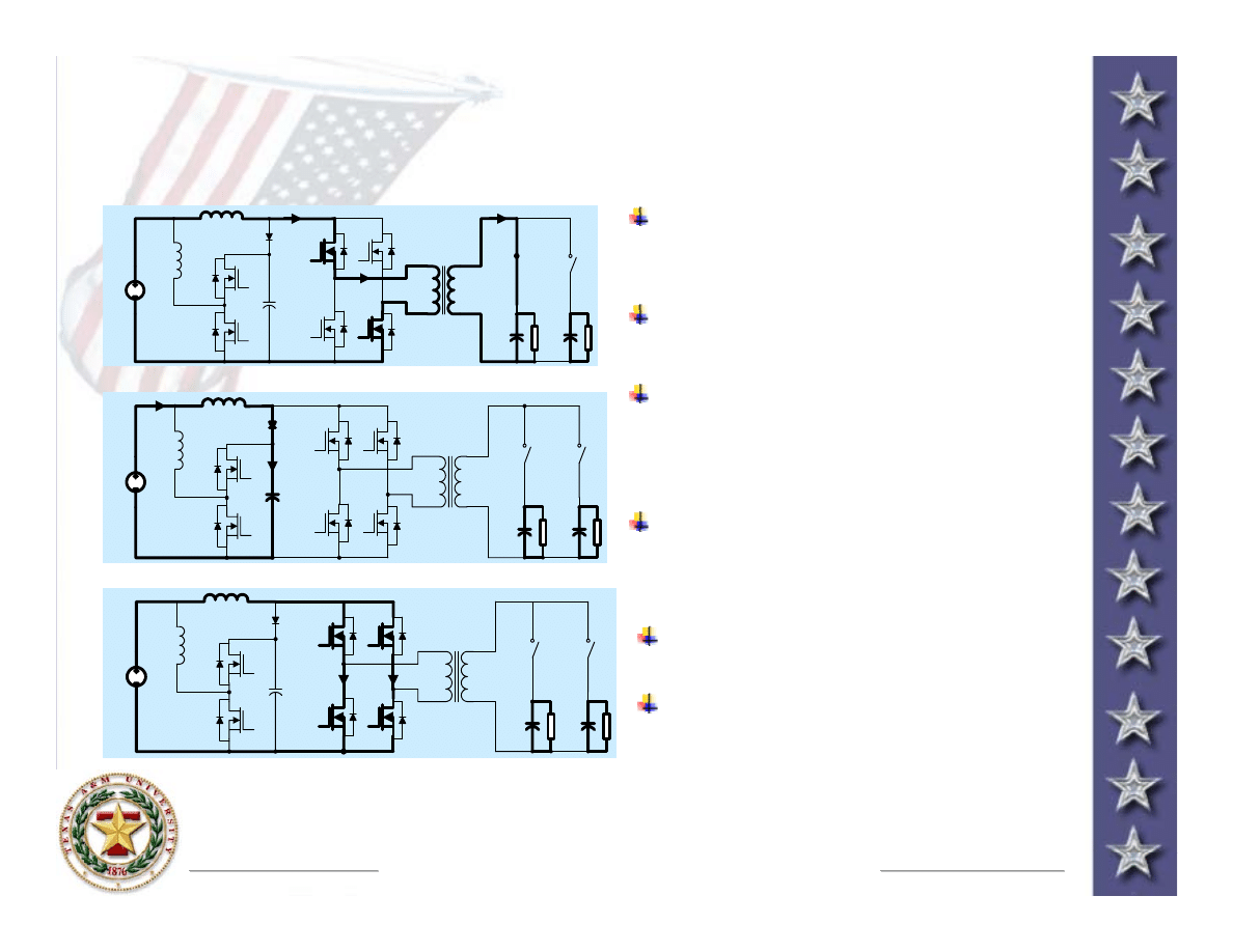
Current
Current
-
-
fed High Frequency Link
fed High Frequency Link
Direct DC to AC Converters for SOFC
Direct DC to AC Converters for SOFC
L
s
C
oA
L
f
C
f
Q
5
Q
6
D
f
Q
1
Q
2
Q
4
Q
3
T1
−
−
v
cf
S
1
S
2
C
oA
v
oA
+
−
v
oB
+
−
v
AB
+
−
+
i
Ls
i
Lf
i
s
1 : n
i
T2
Fuel
Cell
V
DC
+
−
+
v
Current
Current
-
-
fed direct DC to AC power conversion of fuel cell voltage
fed direct DC to AC power conversion of fuel cell voltage
(22V) to 120/240V AC, 60Hz
(22V) to 120/240V AC, 60Hz
Consists of full
Consists of full
-
-
bridge inverter Q1
bridge inverter Q1
-
-
Q4, HF transformer, simplified
Q4, HF transformer, simplified
AC
AC
-
-
AC converter
AC converter
The switches Q5, Q6 (are optional) provide input ripple current
The switches Q5, Q6 (are optional) provide input ripple current
(120Hz) cancellation
(120Hz) cancellation
Power Electronics & Clean Power Research Laboratory
Power Electronics & Clean Power Research Laboratory
http://enjeti.tamu.edu
http://enjeti.tamu.edu
Texas A&M University
Texas A&M University
http://www.tamu.edu
http://www.tamu.edu
Current
Current
-
-
fed High Frequency Link
fed High Frequency Link
Direct DC to AC Converters for SOFC
Direct DC to AC Converters for SOFC
L
s
C
oA
L
f
C
f
Q
5
Q
6
D
f
Q
1
Q
2
Q
4
Q
3
T1
−
−
v
cf
S
1
S
2
C
oA
v
oA
+
−
v
oB
+
−
v
AB
+
−
+
i
Ls
i
Lf
i
s
1 : n
i
T2
Fuel
Cell
V
DC
+
−
+
v
Full
Full
-
-
bridge inverter offers lower switch stress, simple voltage
bridge inverter offers lower switch stress, simple voltage
clamping and transformer flux balance
clamping and transformer flux balance
The switches Q5, Q6, Lf (optional components) provide active
The switches Q5, Q6, Lf (optional components) provide active
filtering function: i.e. cancellation of fuel cell input ripple
filtering function: i.e. cancellation of fuel cell input ripple
current
current
The converter has three operating modes
The converter has three operating modes
Power Electronics & Clean Power Research Laboratory
Power Electronics & Clean Power Research Laboratory
http://enjeti.tamu.edu
http://enjeti.tamu.edu
Texas A&M University
Texas A&M University
http://www.tamu.edu
http://www.tamu.edu
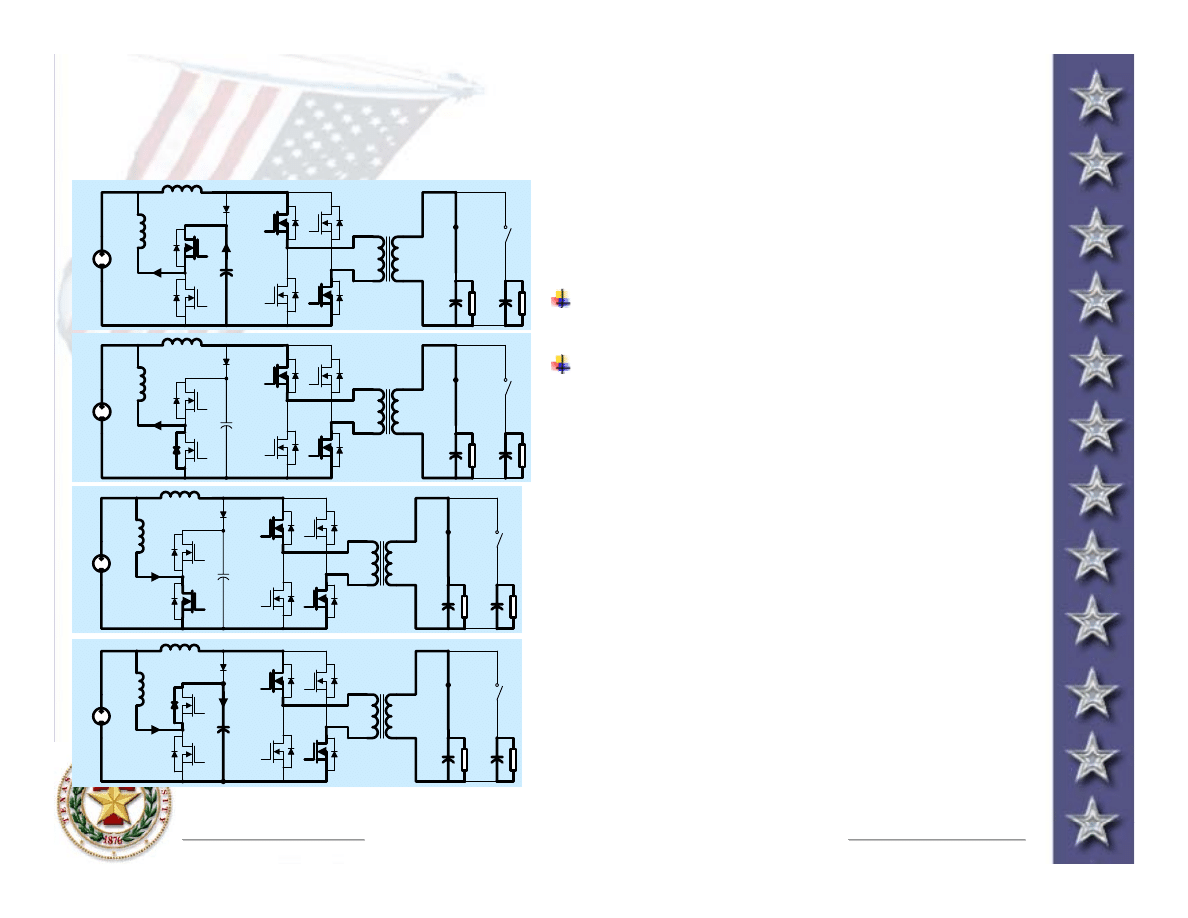
Current
Current
-
-
fed Direct DC to AC Converter:
fed Direct DC to AC Converter:
Operating Modes
Operating Modes
V
D C
Powering mode: Diagonal
Powering mode: Diagonal
switches Q1, Q4 or Q2, Q3 are
switches Q1, Q4 or Q2, Q3 are
turned
turned
-
-
on.
on.
Primary inductor current is
Primary inductor current is
transferred to secondary side
transferred to secondary side
V
D C
Restoring mode: switches are
Restoring mode: switches are
turned
turned
-
-
off, the inductor current
off, the inductor current
flows via the diode
flows via the diode
Df
Df
and
and
charges the input capacitor
charges the input capacitor
Capacitor voltage is controlled
Capacitor voltage is controlled
by Q5, Q6 and is maintained
by Q5, Q6 and is maintained
higher than fuel cell voltage
higher than fuel cell voltage
V
D C
Restoring mode: switches
Restoring mode: switches
Q1
Q1
-
-
Q4 are turned
Q4 are turned
-
-
on
on
Primary inductor current
Primary inductor current
increases at the rate of
increases at the rate of
Vdc
Vdc
/Ls
/Ls
Power Electronics & Clean Power Research Laboratory
Power Electronics & Clean Power Research Laboratory
http://enjeti.tamu.edu
http://enjeti.tamu.edu
Texas A&M University
Texas A&M University
http://www.tamu.edu
http://www.tamu.edu
Current
Current
-
-
fed Direct DC to AC Converter:
fed Direct DC to AC Converter:
Operating Modes
Operating Modes
V
D C
V
D C
Input ripple current cancellation
Input ripple current cancellation
modes are shown in this figure
modes are shown in this figure
Capacitor voltage is controlled
Capacitor voltage is controlled
by Q5, Q6 and is maintained
by Q5, Q6 and is maintained
higher than fuel cell voltage
higher than fuel cell voltage
V
D C
V
D C
Power Electronics & Clean Power Research Laboratory
Power Electronics & Clean Power Research Laboratory
http://enjeti.tamu.edu
http://enjeti.tamu.edu
Texas A&M University
Texas A&M University
http://www.tamu.edu
http://www.tamu.edu
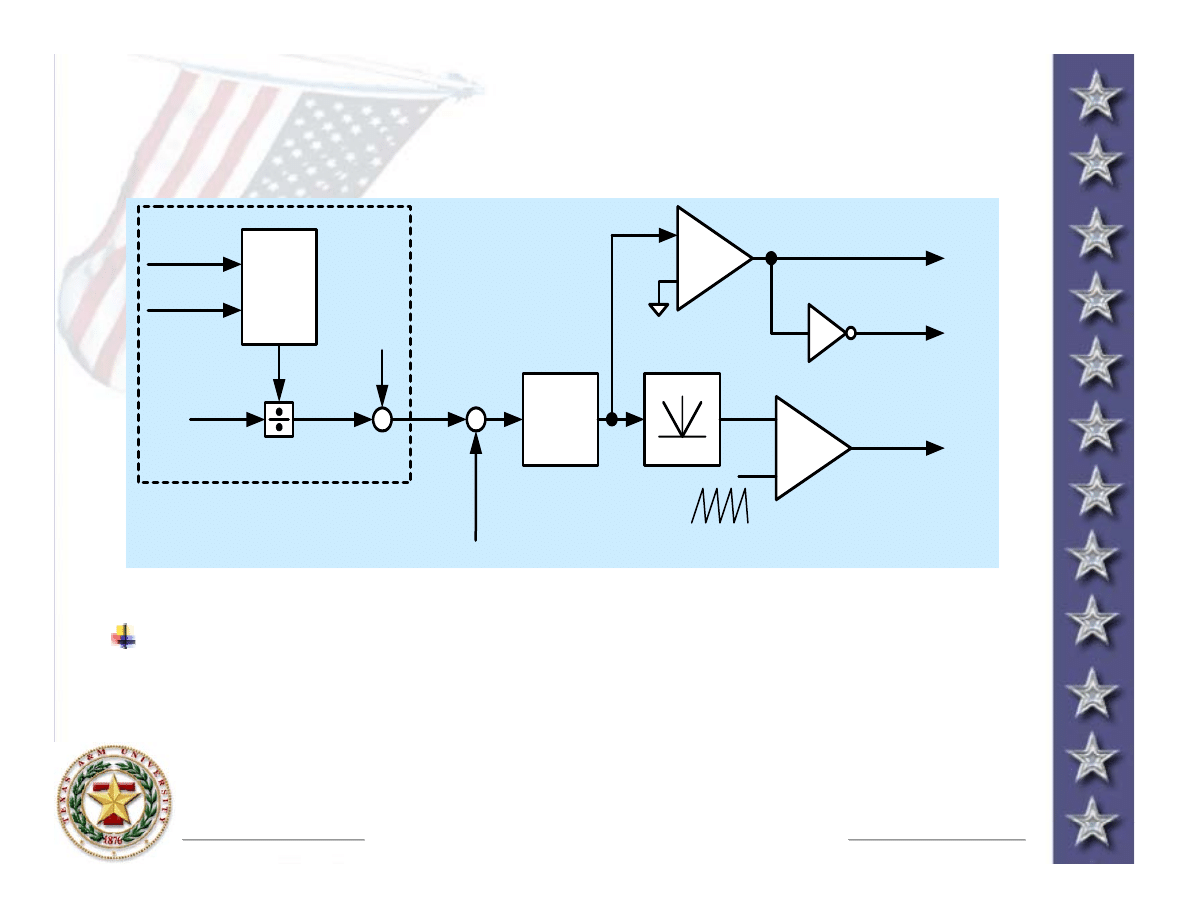
Direct DC to AC Converter
Direct DC to AC Converter
Control Strategy
Control Strategy
+
−
G
v
(s)
abs
Q
1
, Q
4
Q
2
, Q
3
v
o
*
+
−
v
o
+
−
phase
shift
Logic
C ircuit
S
1
, S
2
i
T 2
S
1
S
2
v
o A
= p o s itiv e h a lf c y c le
v
o B
= n e g a tiv e h a lf c y c le
Voltage control strategy for the direct DC to AC Converter
Voltage control strategy for the direct DC to AC Converter
A proportional (P) controller is used for
A proportional (P) controller is used for
Gv(s
Gv(s
)
)
The bi
The bi
-
-
directional switches S1, S2 are selected based on the input curr
directional switches S1, S2 are selected based on the input curr
ent
ent
polarity
polarity
Power Electronics & Clean Power Research Laboratory
Power Electronics & Clean Power Research Laboratory
http://enjeti.tamu.edu
http://enjeti.tamu.edu
Texas A&M University
Texas A&M University
http://www.tamu.edu
http://www.tamu.edu
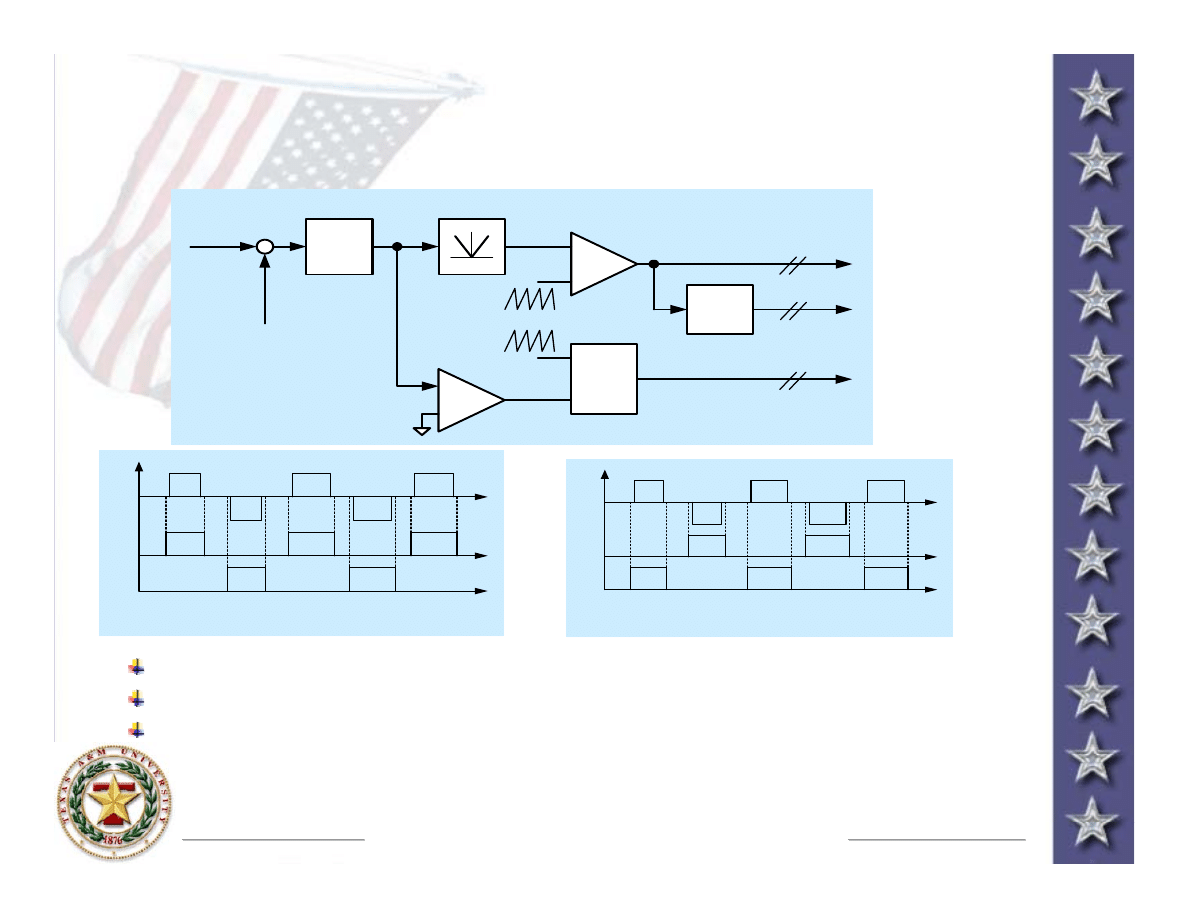
Direct DC to AC Converter
Direct DC to AC Converter
Control Strategy
Control Strategy
+
v
oA
, v
oB
i
oA
, i
oB
P
av
V
dc
avg.
power
cal.
i
s,av
−
i
Ls
i
Lf
*
i
Lf
G
f
(s)
+
−
abs
+
−
+
−
buck mode
boost mode
PWM pulse
reference calculation
The above control block diagram is used to
The above control block diagram is used to
actively cancel the low frequency ripple current
actively cancel the low frequency ripple current
from the fuel cell input current
from the fuel cell input current
Power Electronics & Clean Power Research Laboratory
Power Electronics & Clean Power Research Laboratory
http://enjeti.tamu.edu
http://enjeti.tamu.edu
Texas A&M University
Texas A&M University
http://www.tamu.edu
http://www.tamu.edu
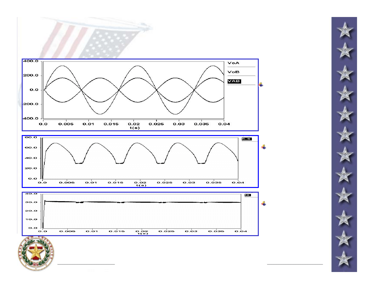
Direct DC to AC Converter
Direct DC to AC Converter
Simulation Results
Simulation Results
Output Voltage
Output Voltage
120V/240V, 60Hz
120V/240V, 60Hz
Input inductor
Input inductor
current
current
Fuel cell input
Fuel cell input
current
current

Power Electronics & Clean Power Research Laboratory
Power Electronics & Clean Power Research Laboratory
http://enjeti.tamu.edu
http://enjeti.tamu.edu
Texas A&M University
Texas A&M University
http://www.tamu.edu
http://www.tamu.edu
Activities for the Next 6
Activities for the Next 6
-
-
12 months
12 months
Task # 1: Design
: A detailed design of the proposed direct DC to
AC converters will be completed: high frequency transformer
design, component ratings, protection circuitry, hardware layout
will be completed followed by a comprehensive simulation of the
FCI systems. The design will be optimized to handle wide input
voltage range and output load swings.
Completed
Task # 2:
Task # 2:
Evaluation of Fuel Cell Ripple Current & Energy Storage
Evaluation of Fuel Cell Ripple Current & Energy Storage
:
:
A trade study will be initiated to study the performance of vari
A trade study will be initiated to study the performance of vari
ous
ous
types of input filter designs
types of input filter designs
Task # 3:
Task # 3:
Hardware Construction & Testing
Hardware Construction & Testing
: Hardware
: Hardware
components will be procured for the development of the
components will be procured for the development of the
proposed converters and tested with DSP control in open loop
proposed converters and tested with DSP control in open loop
Task # 4:
Task # 4:
Testing & Verification
Testing & Verification
: The proposed converters will
: The proposed converters will
undergo linear & nonlinear load testing on a SOFC fuel cell
undergo linear & nonlinear load testing on a SOFC fuel cell
simulator. These tests will be conducted in coordination with
simulator. These tests will be conducted in coordination with
SECA Industrial partner: Delphi
SECA Industrial partner: Delphi
-
-
Auto
Auto
Power Electronics & Clean Power Research Laboratory
Power Electronics & Clean Power Research Laboratory
http://enjeti.tamu.edu
http://enjeti.tamu.edu
Texas A&M University
Texas A&M University
http://www.tamu.edu
http://www.tamu.edu
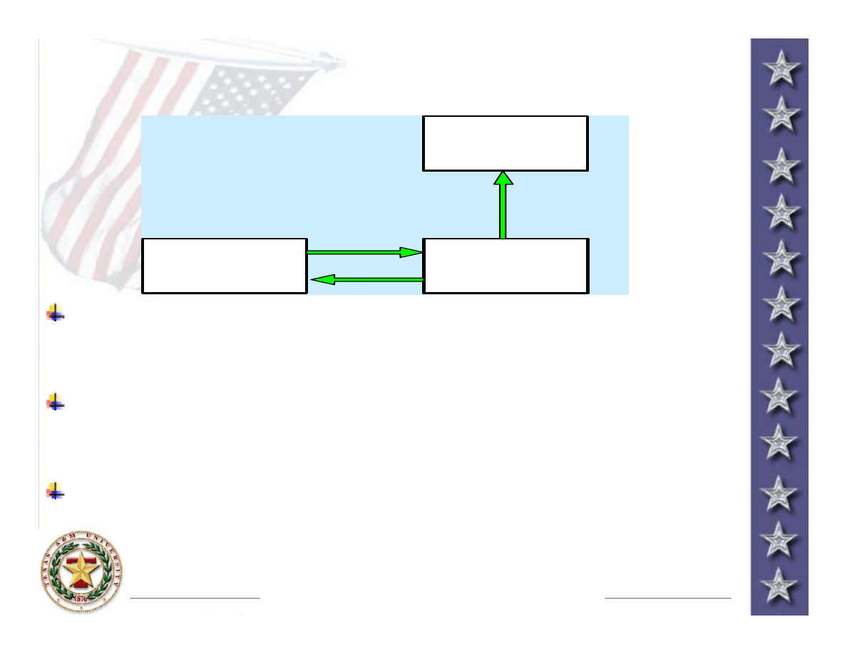
SOFC Fuel Cell Simulator Development
SOFC Fuel Cell Simulator Development
to assist in testing/validation
to assist in testing/validation
The purpose of the fuel cell simulator is to enable
The purpose of the fuel cell simulator is to enable
testing and validation of power conditioning module
testing and validation of power conditioning module
performance under various loading conditions
performance under various loading conditions
A programmable DC power supply (0
A programmable DC power supply (0
-
-
55V, 10kW) is
55V, 10kW) is
controlled via
controlled via
Labview
Labview
to emulate V
to emulate V
-
-
I characteristics
I characteristics
of a SOFC
of a SOFC
Labview
Labview
is employed for SOFC V
is employed for SOFC V
-
-
I curve fitting and
I curve fitting and
emulation
P o w e r S u p p l y
A u t o m a t i c C o m p u t e r
C o n t r o l
U s e r V i s u a l i z a t i o n o n
C o m p u t e r
V o l t a g e a n d
C u r r e n t
F e e d b a c k
C o m m a n d e d
V o l t a g e
emulation
Document Outline
- Development of High Frequency Link Direct DC to AC Converters for Solid Oxide Fuel Cells (SOFC)
- High Frequency Link Direct DC to AC Converters for SOFC
Wyszukiwarka
Podobne podstrony:
więcej podobnych podstron