
Guide to Creating and Configuring a Server Cluster under
Topics on this Page
Checklists for Server Cluster Configuration
Configuring the Cluster Service
Post-Installation Configuration
By Elden Christensen
Microsoft Corporation
Published: Last modified 5/30/2003
Abstract
This guide provides step-by-step instructions for creating and configuring a typical single quorum device
multi-node server cluster using a shared disk on servers running the Microsoft® Windows® Server 2003
Enterprise Edition and Windows Server 2003 Datacenter Edition operating systems.
Introduction
A server cluster is a group of independent servers working collectively and running the Microsoft Cluster
Service (MSCS). Server clusters provide high availability, failback, scalability, and manageability for
resources and applications
Server clusters allow client access to applications and resources in the event of failures and planned
outages. If one of the servers in the cluster is unavailable because of a failure or maintenance
requirements, resources and applications move to other available cluster nodes.
For Windows Clustering solutions, the term “high availability” is used rather than “fault tolerant.” Fault-
tolerant technology offers a higher level of resilience and recovery. Fault-tolerant servers typically use a

high degree of hardware redundancy plus specialized software to provide near-instantaneous recovery
from any single hardware or software fault. These solutions cost significantly more than a Windows
Clustering solution because organizations must pay for redundant hardware that waits in an idle state for
a fault.
Server clusters do not guarantee non-stop operation, but they do provide sufficient availability for most
mission-critical applications. The cluster service can monitor applications and resources and automatically
recognize and recover from many failure conditions. This provides flexibility in managing the workload
within a cluster. It also improves overall system availability.
Cluster service benefits include:
•
High Availability: With server clusters, ownership of resources such as disk drives and Internet
protocol (IP) addresses is automatically transferred from a failed server to a surviving server. When
a system or application in the cluster fails, the cluster software restarts the failed application on a
surviving server, or disperses the work from the failed node to the remaining nodes. As a result,
users experience only a momentary pause in service.
•
Failback: The Cluster service will automatically re-assign the workload in a cluster when a failed
server comes back online to its predetermined preferred owner. This feature can be configured, but
is disabled by default.
•
Manageability: You can use the Cluster Administrator tool (CluAdmin.exe) to manage a cluster
as a single system and to manage applications as if they were running on a single server. You can
move applications to different servers within the cluster. Cluster Administrator can be used to
manually balance server workloads and to free servers for planned maintenance. You can also
monitor the status of the cluster, all nodes, and resources from anywhere on the network.
•
Scalability: Cluster services can grow to meet increased demand. When the overall load for a
cluster-aware application exceeds the cluster’s capabilities, additional nodes can be added.
This document provides instructions for creating and configuring a server cluster with servers connected to
a shared cluster storage device and running Windows Server 2003 Enterprise Edition or Windows Server
2003 Datacenter Edition. Intended to guide you through the process of installing a typical cluster, this
document does not explain how to install clustered applications. Windows Clustering solutions that
implement non-traditional quorum models, such as Majority Node Set (MNS) clusters and geographically
dispersed clusters, also are not discussed. For additional information about server cluster concepts as well
as installation and configuration procedures, see the Windows Server 2003 Online Help.
Checklists for Server Cluster Configuration:

This checklist helps you prepare for installation. Step-by-step instructions begin after the checklist.
Software Requirements
•
Microsoft Windows Server 2003 Enterprise Edition or Windows Server 2003 Datacenter Edition
installed on all computers in the cluster.
•
A name resolution method such as Domain Name System (DNS), DNS dynamic update protocol,
Windows Internet Name Service (WINS), HOSTS, and so on.
•
An existing domain model.
•
All nodes must be members of the same domain.
•
A domain-level account that is a member of the local administrators group on each node. A
dedicated account is recommended.
Hardware Requirements
•
Clustering hardware must be on the cluster service Hardware Compatibility List (HCL). To find the
latest version of the cluster service HCL, go to the Windows Hardware Compatibility List at
http://www.microsoft.com/whdc/hcl/default.mspx
, and then search for cluster. The entire solution
must be certified on the HCL, not just the individual components. For additional information, see the
following article in the Microsoft Knowledge Base:
The Microsoft Support Policy for Server Clusters and the Hardware
Note If you are installing this cluster on a storage area network (SAN) and plan to have
multiple devices and clusters sharing the SAN with a cluster, the solution must also be on
the “Cluster/Multi-Cluster Device” Hardware Compatibility List. For additional information,
see the following article in the Microsoft Knowledge Base:
Support for Multiple Clusters Attached to the Same SAN Device
•
Two mass storage device controllers—Small Computer System Interface (SCSI) or Fibre Channel.
A local system disk for the operating system (OS) to be installed on one controller. A separate
peripheral component interconnect (PCI) storage controller for the shared disks.

•
Two PCI network adapters on each node in the cluster.
•
Storage cables to attach the shared storage device to all computers. Refer to the manufacturers
instructions for configuring storage devices. See the appendix that accompanies this article for
additional information on specific configuration needs when using SCSI or Fibre Channel.
•
All hardware should be identical, slot for slot, card for card, BIOS, firmware revisions, and so on,
for all nodes. This makes configuration easier and eliminates compatibility problems.
Network Requirements
•
A unique NetBIOS name.
•
Static IP addresses for all network interfaces on each node.
Note Server Clustering does not support the use of IP addresses assigned from Dynamic Host
Configuration Protocol (DHCP) servers.
•
Access to a domain controller. If the cluster service is unable to authenticate the user account
used to start the service, it could cause the cluster to fail. It is recommended that you have a domain
controller on the same local area network (LAN) as the cluster is on to ensure availability.
•
Each node must have at least two network adapters—one for connection to the client public
network and the other for the node-to-node private cluster network. A dedicated private network
adapter is required for HCL certification.
•
All nodes must have two physically independent LANs or virtual LANs for public and private
communication.
•
If you are using fault-tolerant network cards or network adapter teaming, verify that you are
using the most recent firmware and drivers. Check with your network adapter manufacturer for
cluster compatibility.
Shared Disk Requirements:
•
An HCL-approved external disk storage unit connected to all computers. This will be used as the
clustered shared disk. Some type of a hardware redundant array of independent disks (RAID) is
recommended.
•
All shared disks, including the quorum disk, must be physically attached to a shared bus.
Note The requirement above does not hold true for Majority Node Set (MNS) clusters, which are

not covered in this guide.
•
Shared disks must be on a different controller then the one used by the system drive.
•
Creating multiple logical drives at the hardware level in the RAID configuration is recommended
rather than using a single logical disk that is then divided into multiple partitions at the operating
system level. This is different from the configuration commonly used for stand-alone servers.
However, it enables you to have multiple disk resources and to do Active/Active configurations and
manual load balancing across the nodes in the cluster.
•
A dedicated disk with a minimum size of 50 megabytes (MB) to use as the quorum device. A
partition of at least 500 MB is recommended for optimal NTFS file system performance.
•
Verify that disks attached to the shared bus can be seen from all nodes. This can be checked at
the host adapter setup level. Refer to the manufacturer’s documentation for adapter-specific
instructions.
•
SCSI devices must be assigned unique SCSI identification numbers and properly terminated
according to the manufacturer’s instructions. See the appendix with this article for information on
installing and terminating SCSI devices.
•
All shared disks must be configured as basic disks. For additional information, see the following
article in the Microsoft Knowledge Base:
Dynamic Disk Configuration Unavailable for Server Cluster Disk Resources
•
Software fault tolerance is not natively supported on cluster shared disks.
•
All shared disks must be configured as master boot record (MBR) disks on systems running the
64-bit versions of Windows Server 2003.
•
All partitions on the clustered disks must be formatted as NTFS.
•
Hardware fault-tolerant RAID configurations are recommended for all disks.
•
A minimum of two logical shared drives is recommended.
Cluster Installation
Installation Overview
During the installation process, some nodes will be shut down while others are being installed. This step

helps guarantee that data on disks attached to the shared bus is not lost or corrupted. This can happen
when multiple nodes simultaneously try to write to a disk that is not protected by the cluster software.
The default behavior of how new disks are mounted has been changed in Windows 2003 Server from the
behavior in the Microsoft® Windows® 2000 operating system. In Windows 2003, logical disks that are not
on the same bus as the boot partition will not be automatically mounted and assigned a drive letter. This
helps ensure that the server will not mount drives that could possibly belong to another server in a
complex SAN environment. Although the drives will not be mounted, it is still recommended that you
follow the procedures below to be certain the shared disks will not become corrupted.
Use the table below to determine which nodes and storage devices should be turned on during each step.
The steps in this guide are for a two-node cluster. However, if you are installing a cluster with more than
two nodes, the Node 2 column lists the required state of all other nodes.
Step Node
1
Node
2
Storage Comments
Setting up networks On
On
Off
Verify that all storage devices on the
shared bus are turned off. Turn on all
nodes.
Setting up shared
disks
On
Off
On
Shutdown all nodes. Turn on the
shared storage, then turn on the first
node.
Verifying disk
configuration
Off
On
On
Turn on the first node, turn on second
node. Repeat for nodes 3 and 4 if
necessary.
Configuring the first
node
On
Off
On
Turn off all nodes; turn on the first
node.
Configuring the
second node
On On On
Turn on the second node after the first
node is successfully configured.
Repeat for nodes 3 and 4 as
necessary.
Post-installation
On
On
On
All nodes should be on.
Several steps must be taken before configuring the Cluster service software. These steps are:
•
Installing Windows Server 2003 Enterprise Edition or Windows Server 2003 Datacenter Edition
operating system on each node.
•
Setting up networks.
•
Setting up disks.
Perform these steps on each cluster node before proceeding with the installation of cluster service on the
first node.
To configure the cluster service, you must be logged on with an account that has administrative

permissions to all nodes. Each node must be a member of the same domain. If you choose to make one of
the nodes a domain controller, have another domain controller available on the same subnet to eliminate
a single point of failure and enable maintenance on that node.
Installing the Windows Server 2003 Operating System
Refer to the documentation you received with the Windows Server 2003 operating system package to
install the system on each node in the cluster.
Before configuring the cluster service, you must be logged on locally with a domain account that is a
member of the local administrators group.
Note The installation will fail if you attempt to join a node to a cluster that has a blank password for the
local administrator account. For security reasons, Windows Server 2003 prohibits blank administrator
passwords.
Setting Up Networks
Each cluster node requires at least two network adapters with two or more independent networks, to
avoid a single point of failure. One is to connect to a public network, and one is to connect to a private
network consisting of cluster nodes only. Servers with multiple network adapters are referred to as “multi-
homed.” Because multi-homed servers can be problematic, it is critical that you follow the network
configuration recommendations outlined in this document.
Microsoft requires that you have two Peripheral Component Interconnect (PCI) network adapters in each
node to be certified on the Hardware Compatibility List (HCL) and supported by Microsoft Product Support
Services. Configure one of the network adapters on your production network with a static IP address, and
configure the other network adapter on a separate network with another static IP address on a different
subnet for private cluster communication.
Communication between server cluster nodes is critical for smooth cluster operations. Therefore, you must
configure the networks that you use for cluster communication are configured optimally and follow all
hardware compatibility list requirements.
The private network adapter is used for node-to-node communication, cluster status information, and
cluster management. Each node’s public network adapter connects the cluster to the public network where
clients reside and should be configured as a backup route for internal cluster communication. To do so,
configure the roles of these networks as either "Internal Cluster Communications Only" or "All
Communications" for the Cluster service.
Additionally, each cluster network must fail independently of all other cluster networks. This means that
two cluster networks must not have a component in common that can cause both to fail simultaneously.
For example, the use of a multiport network adapter to attach a node to two cluster networks would not
satisfy this requirement in most cases because the ports are not independent.
To eliminate possible communication issues, remove all unnecessary network traffic from the network
adapter that is set to Internal Cluster communications only (this adapter is also known as the
heartbeat or private network adapter).
To verify that all network connections are correct, private network adapters must be on a network that is
on a different logical network from the public adapters. This can be accomplished by using a cross-over
cable in a two-node configuration or a dedicated dumb hub in a configuration of more than two nodes. Do
not use a switch, smart hub, or any other routing device for the heartbeat network.
Note Cluster heartbeats cannot be forwarded through a routing device because their Time to Live (TTL)
is set to 1. The public network adapters must be only connected to the public network. If you have a
virtual LAN, then the latency between the nodes must be less then 500 milliseconds (ms). Also, in
Windows Server 2003, heartbeats in Server Clustering have been changed to multicast; therefore, you
may want to make a Madcap server available to assign the multicast addresses. For additional
information, see the following article in the Microsoft Knowledge Base:
Multicast Support Enabled for the Cluster Heartbeat
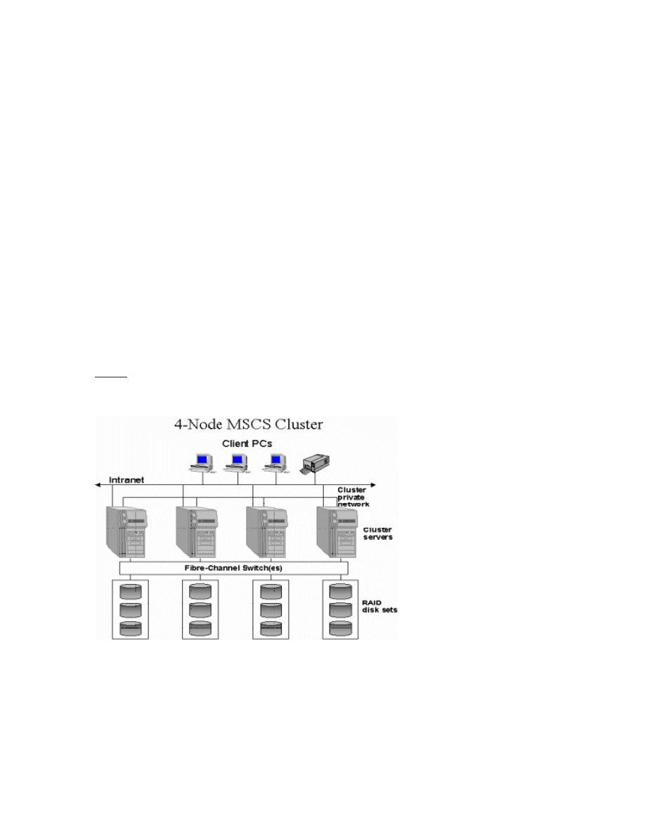
Figure 1 below outlines a four-node cluster configuration.
Figure 1 Connections for a four-node cluster.
General Network Configuration:
Note This guide assumes that you are running the default Start menu. The steps may be slightly
different if you are running the Classic Start menu. Also, which network adapter is private and which is
public depends upon your wiring. For the purposes of this white paper, the first network adapter (Local
Area Connection) is connected to the public network, and the second network adapter (Local Area
Connection 2) is connected to the private cluster network. Your network may be different.
To Rename the Local Area Network Icons
It is recommended that you change the names of the network connections for clarity. For example, you
might want to change the name of Local Area Connection 2 to something like Private. Renaming will help
you identify a network and correctly assign its role.
1.
Click Start, point to Control Panel, right-click Network Connections, and then click Open
2.
Right-click the Local Area Connection 2 icon.
3.
Click Rename.
4.
Type Private in the textbox, and then press ENTER.
5.
Repeat steps 1 through 3, and then rename the public network adapter as Public.
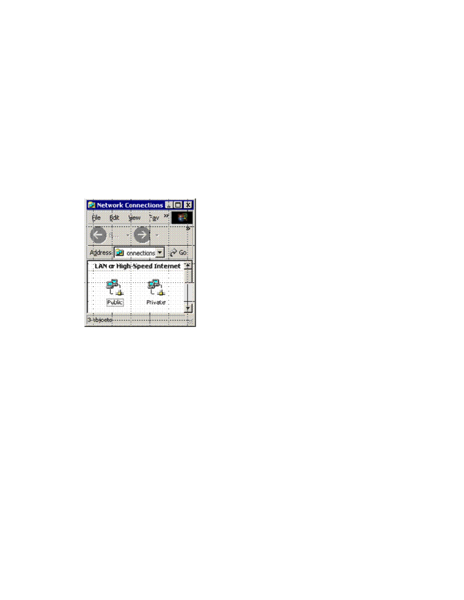
Figure 2 Renamed icons in the Network Connections window.
6.
The renamed icons should look like those in Figure 2 above. Close the Network Connections
window. The new connection names will appear in Cluster Administrator and automatically replicate
to all other cluster nodes as they are brought online.
To Configure the Binding Order Networks on All Nodes
1.
Click Start, point to Control Panel, right-click Network Connections, and then click Open
2.
On the Advanced menu, click Advanced Settings.
3.
In the Connections box, make sure that your bindings are in the following order, and then click
OK:
a.
Public
b.
Private
c.
Remote Access Connections
Configuring the Private Network Adapter
1.
Right-click the network connection for your heartbeat adapter, and then click Properties.
2.
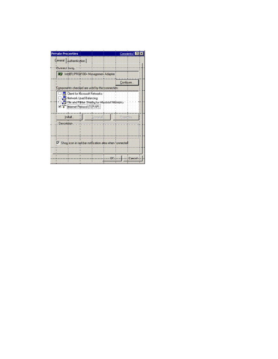
On the General tab, make sure that only the Internet Protocol (TCP/IP) check box is
selected, as shown in Figure 3 below. Click to clear the check boxes for all other clients, services, and
protocols.
Figure 3 Click to select only the Internet Protocol check box in the Private Properties
dialog box.
3.
If you have a network adapter that is capable of transmitting at multiple speeds, you should
manually specify a speed and duplex mode. Do not use an auto-select setting for speed, because
some adapters may drop packets while determining the speed. The speed for the network adapters
must be hard set (manually set) to be the same on all nodes according to the card manufacturer's
specification. If you are not sure of the supported speed of your card and connecting devices,
Microsoft recommends you set all devices on that path to 10 megabytes per second (Mbps) and
Half Duplex, as shown in Figure 4 below. The amount of information that is traveling across the
heartbeat network is small, but latency is critical for communication. This configuration will provide
enough bandwidth for reliable communication. All network adapters in a cluster attached to the same
network must be configured identically to use the same Duplex Mode, Link Speed, Flow Control,
and so on. Contact your adapter's manufacturer for specific information about appropriate speed and
duplex settings for your network adapters.
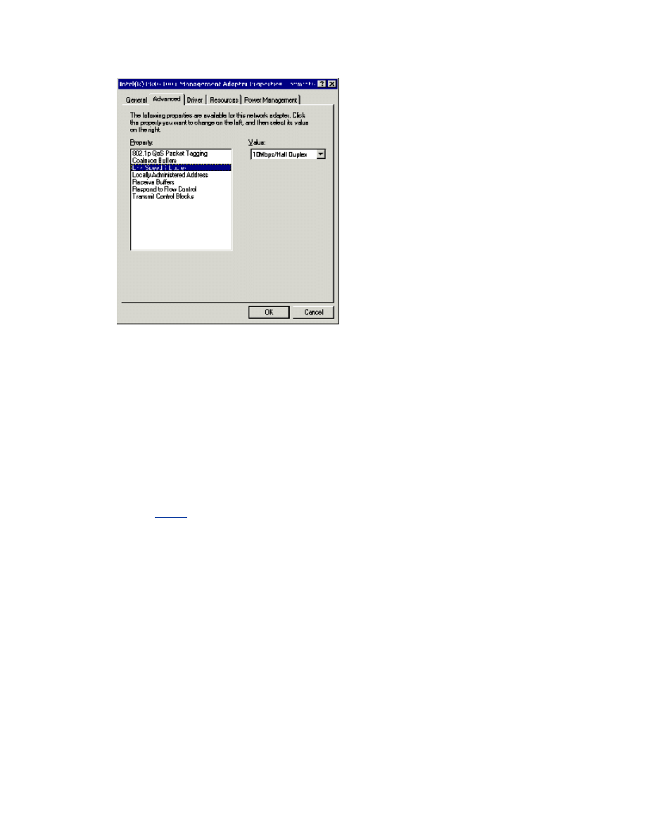
Figure 4 Setting the speed and duplex for all adaptors.
Note Microsoft does not recommended that you use any type of fault-tolerant adapter or
"Teaming" for the heartbeat. If you require redundancy for your heartbeat connection, use
multiple network adapters set to Internal Communication Only and define their network
priority in the Cluster configuration. Issues seen with early multi-ported network adapters,
verify that your firmware and driver are at the most current revision if you use this
technology.
Contact your network adapter manufacturer for information about compatibility on a server
cluster. For additional information, see the following article in the Microsoft Knowledge Base:
Network Adapter Teaming and Server Clustering
4.
Click Internet Protocol (TCP/IP), and then click Properties.
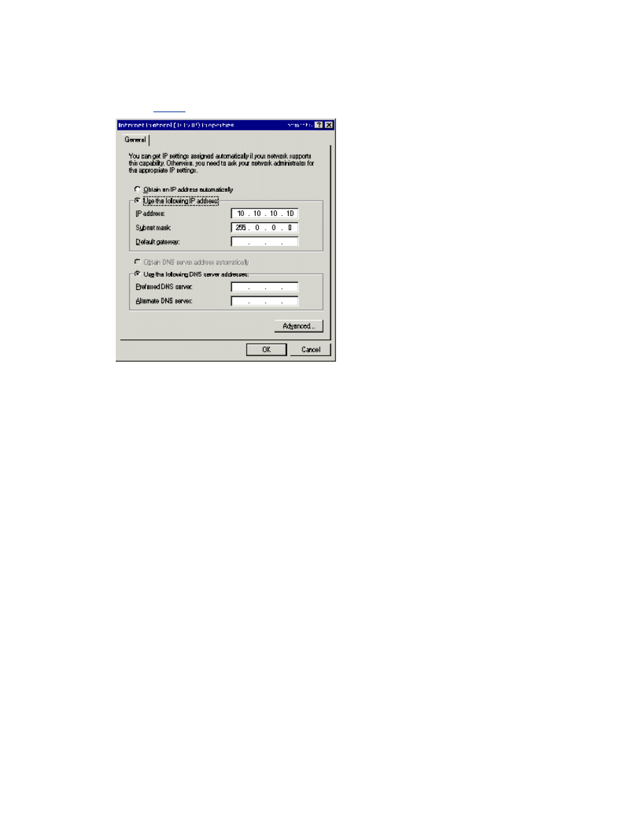
5.
On the General tab, verify that you have selected a static IP address that is not on the same
subnet or network as any other public network adapter. It is recommended that you put the private
network adapter in one of the following private network ranges:
•
10.0.0.0 through 10.255.255.255 (Class A)
•
172.16.0.0 through 172.31.255.255 (Class B)
•
192.168.0.0 through 192.168.255.255 (Class C)
An example of a good IP address to use for the private adapters is 10.10.10.10 on node 1 and
10.10.10.11 on node 2 with a subnet mask of 255.0.0.0, as shown in Figure 5 below. Be sure that
this is a completely different IP address scheme then the one used for the public network.
Note For additional information about valid IP addressing for a private network, see the
following article in the Microsoft Knowledge Base:
Valid IP Addressing for a Private Network
Figure 5 An example of an IP address to use for private adapters.
6.
Verify that there are no values defined in the Default Gateway box or under Use the
Following DNS server addresses.
7.
Click the Advanced button.
8.
On the DNS tab, verify that no values are defined. Make sure that the Register this
connection's addresses in DNS and Use this connection's DNS suffix in DNS registration
check boxes are cleared.
9.
On the WINS tab, verify that there are no values defined. Click Disable NetBIOS over TCP/IP
as shown in Figure 6 below.
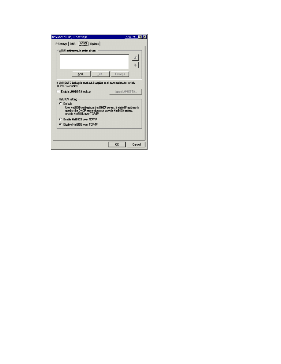
Figure 6 Verify that no values are defined on the WINS tab.
10.
When you close the dialog box, you may receive the following prompt: “This connection has an
empty primary WINS address. Do you want to continue?” If you receive this prompt, click Yes
11.
Complete steps 1 through 10 on all other nodes in the cluster with different static IP addresses.
Configuring the Public Network Adapter
Note If IP addresses are obtained via DHCP, access to cluster nodes may be unavailable if the DHCP
server is inaccessible. For this reason, static IP addresses are required for all interfaces on a server
cluster. Keep in mind that cluster service will only recognize one network interface per subnet. If you need
assistance with TCP/IP addressing in Windows Server 2003, please see the Online Help.
Verifying Connectivity and Name Resolution
To verify that the private and public networks are communicating properly, ping all IP addresses from
each node. You should be able to ping all IP addresses, locally and on the remote nodes.
To verify name resolution, ping each node from a client using the node’s machine name instead of its IP
address. It should only return the IP address for the public network. You may also want to try a PING –a
command to do a reverse lookup on the IP Addresses.
Verifying Domain Membership
All nodes in the cluster must be members of the same domain and be able to access a domain controller
and a DNS server. They can be configured as member servers or domain controllers. You should have at
least one domain controller on the same network segment as the cluster. For high availability. another
domain controller should also be available to remove a single point of failure. In this guide, all nodes are

configured as member servers.
There are instances where the nodes may be deployed in an environment where there are no pre-existing
Microsoft® Windows NT® 4.0 domain controllers or Windows Server 2003 domain controllers. This
scenario requires at least one of the cluster nodes to be configured as a domain controller. However, in a
two-node server cluster, if one node is a domain controller, then the other node also must be a domain
controller. In a four-node cluster implementation, it is not necessary to configure all four nodes as domain
controllers. However, when following a “best practices” model and having at least one backup domain
controller, at least one of the remaining three nodes should be configured as a domain controller. A cluster
node must be promoted to a domain controller by using the DCPromo tool before the cluster service is
configured.
The dependence in Windows Server 2003 on the DNS further requires that every node that is a domain
controller also must be a DNS server if another DNS server that supports dynamic updates and/or SRV
records is not available (Active directory integrated zones recommended).
The following issues should be considered when deploying cluster nodes as domain controllers:
•
If one cluster node in a two-node cluster is a domain controller, the other node must be a domain
controller
•
There is overhead associated with running a domain controller. An idle domain controller can use
anywhere between 130 and 140 MB of RAM, which includes having the Clustering service running.
There is also increased network traffic from replication, because these domain controllers have to
replicate with other domain controllers in the domain and across domains.
•
If the cluster nodes are the only domain controllers, then each must be a DNS server as well.
They should point to each other for primary DNS resolution and to themselves for secondary
resolution.
•
The first domain controller in the forest/domain will take on all Operations Master Roles. You can
redistribute these roles to any node. However, if a node fails, the Operations Master Roles assumed
by that node will be unavailable. Therefore, it is recommended that you do not run Operations Master
Roles on any cluster node. This includes Scheme Master, Domain Naming Master, Relative ID Master,
PDC Emulator, and Infrastructure Master. These functions cannot be clustered for high availability
with failover.
•
Clustering other applications such as Microsoft® SQL Server ™ or Microsoft® Exchange Server in
a scenario where the nodes are also domain controllers may not be optimal due to resource

constraints. This configuration should be thoroughly tested in a lab environment before deployment
Because of the complexity and overhead involved in making cluster-nodes domain controllers, it is
recommended that all nodes should be member servers.
Setting Up a Cluster User Account
The Cluster service requires a domain user account that is a member of the Local Administrators group on
each node, under which the Cluster service can run. Because setup requires a user name and password,
this user account must be created before configuring the Cluster service. This user account should be
dedicated only to running the Cluster service, and should not belong to an individual.
Note The cluster service account does not need to be a member of the Domain Administrators group.
For security reasons, granting domain administrator rights to the cluster service account is not
recommended.
The cluster service account requires the following rights to function properly on all nodes in the cluster.
The Cluster Configuration Wizard grants the following rights automatically:
•
Act as part of the operating system
•
Adjust memory quotas for a process
•
Back up files and directories
•
Increase scheduling priority
•
Log on as a service
•
Restore files and directories
For additional information, see the following article in the Microsoft Knowledge Base:
How to Manually Re-Create the Cluster Service Account
To Set Up a Cluster User Account
1.
Click Start, point to All Programs, point to Administrative Tools, and then click Active
Directory Users and Computers.
2.
Click the plus sign (+) to expand the domain if it is not already expanded.
3.
Right-click Users, point to New, and then click User.
4.
Type the cluster name, as shown in Figure 7 below, and then click Next.
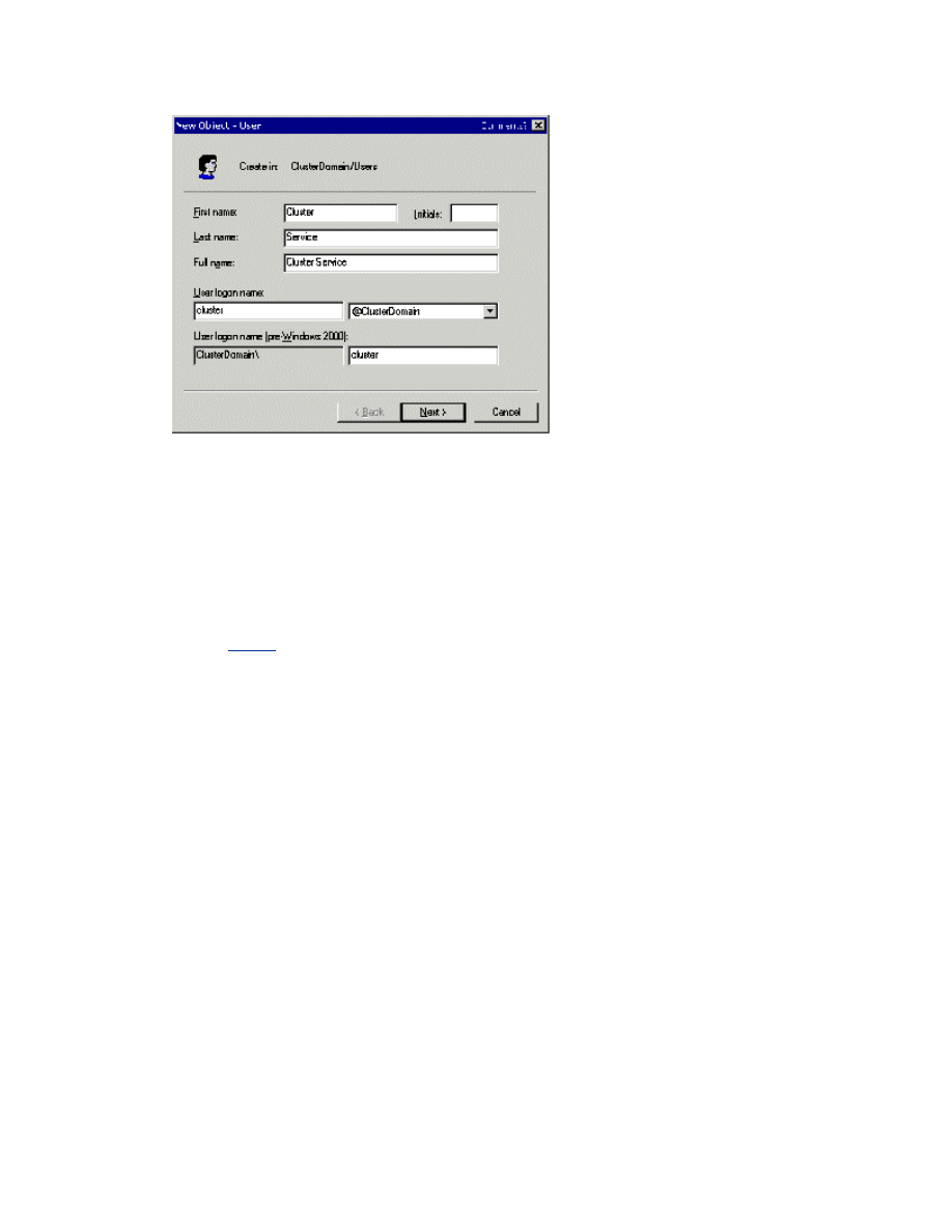
Figure 7 Type the cluster name.
5.
Set the password settings to User Cannot Change Password and Password Never Expires.
Click Next, and then click Finish to create this user.
Note If your administrative security policy does not allow the use of passwords that never expire,
you must renew the password and update the cluster service configuration on each node before
password expiration. For additional information, see the following article in the Microsoft Knowledge
Base:
How to Change the Cluster Service Account Password
6.
Right-click Cluster in the left pane of the Active Directory Users and Computers snap-in, and
then click Properties on the shortcut menu.
7.
Click Add Members to a Group.
8.
Click Administrators, and then click OK. This gives the new user account administrative
privileges on this computer.
9.
Quit the Active Directory Users and Computers snap-in.
Setting up Shared Disks
Warning To avoid corrupting the cluster disks, make sure that Windows Server 2003 and the Cluster
service are installed, configured, and running on at least one node before you start an operating system
on another node. It is critical to never have more then one node on until the Cluster service is configured.
To proceed, turn off all nodes. Turn on the shared storage devices, and then turn on node 1.
About the Quorum Disk
The quorum disk is used to store cluster configuration database checkpoints and log files that help
manage the cluster and maintain consistency. The following quorum disk procedures are recommended:
•
Create a logical drive with a minimum size of 50 MB to be used as a quorum disk, 500 MB is
optimal for NTFS.

•
Dedicate a separate disk as a quorum resource.
Important A quorum disk failure could cause the entire cluster to fail; therefore, it is strongly
recommended that you use a volume on a hardware RAID array. Do not use the quorum disk for anything
other than cluster management.
The quorum resource plays a crucial role in the operation of the cluster. In every cluster, a single resource
is designated as the quorum resource. A quorum resource can be any Physical Disk resource with the
following functionality:
•
It replicates the cluster registry to all other nodes in the server cluster. By default, the cluster
registry is stored in the following location on each node: %SystemRoot%\Cluster\Clusdb. The cluster
registry is then replicated to the MSCS\Chkxxx.tmp
file on the quorum drive. These files are exact
copies of each other. The MSCS\Quolog.log file is a transaction log that maintains a record of all
changes to the checkpoint file. This means that nodes that were offline can have these changes
appended when they rejoin the cluster.
•
If there is a loss of communication between cluster nodes, the challenge response protocol is
initiated to prevent a "split brain" scenario. In this situation, the owner of the quorum disk resource
becomes the only owner of the cluster and all the resources. The owner then makes the resources
available for clients. When the node that owns the quorum disk functions incorrectly, the surviving
nodes arbitrate to take ownership of the device. For additional information, see the following article
in the Microsoft Knowledge Base:
How the Cluster Service Takes Ownership of a Disk on the Shared Bus
During the cluster service installation, you must provide the drive letter for the quorum disk. The letter Q
is commonly used as a standard, and Q is used in the example.
To Configure Shared Disks
1.
Make sure that only one node is turned on.
2.
Right click My Computer, click Manage, and then expand Storage.
3.
Double-click Disk Management.
4.
If you connect a new drive, then it automatically starts the Write Signature and Upgrade Disk
Wizard. If this happens, click Next to step through the wizard.
Note The wizard automatically sets the disk to dynamic. To reset the disk to basic, right-click Disk
n (where n specifies the disk that you are working with), and then click Revert to Basic Disk.
5.
Right-click unallocated disk space.
6.
Click New Partition.
7.
The New Partition Wizard begins. Click Next.
8.
Select the Primary Partition partition type. Click Next.
9.
The default is set to maximum size for the partition size. Click Next. (Multiple logical disks are
recommended over multiple partitions on one disk.)
10.
Use the drop-down box to change the drive letter. Use a drive letter that is farther down the
alphabet than the default enumerated letters. Commonly, the drive letter Q is used for the quorum
disk, then R, S,and so on for the data disks. For additional information, see the following article in
the Microsoft Knowledge Base:
Best Practices for Drive-Letter Assignments on a Server Cluster
Note If you are planning on using volume mount points, do not assign a drive letter to the
disk. For additional information, see the following article in the Microsoft Knowledge Base:
How to Configure Volume Mount Points on a Clustered Server
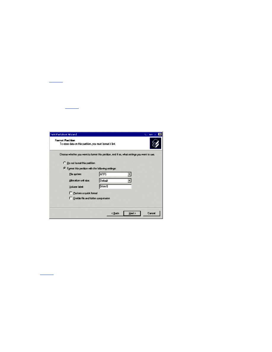
11.
Format the partition using NTFS. In the Volume Label box, type a name for the disk. For
example, Drive Q, as shown in Figure 8 below. It is critical to assign drive labels for shared disks,
because this can dramatically reduce troubleshooting time in the event of a disk recovery situation.
Figure 8 It is critical to assign drive labels for shared disks.
If you are installing a 64-bit version of Windows Server 2003, verify that all disks are formatted as MBR.
Global Partition Table (GPT) disks are not supported as clustered disks. For additional information, see the
following article in the Microsoft Knowledge Base:
Server Clusters Do Not Support GPT Shared Disks
Verify that all shared disks are formatted as NTFS and designated as MBR Basic.
To Verify Disk Access and Functionality
1.
Start Windows Explorer.
2.
Right-click one of the shared disks (such as Drive Q:\), click New, and then click Text

Document.
3.
Verify that you can successfully write to the disk and that the file was created.
4.
Select the file, and then press the Del key to delete it from the clustered disk.
5.
Repeat steps 1 through 4 for all clustered disks to verify they can be correctly accessed from the
first node.
6.
Turn off the first node, turn on the second node, and repeat steps 1 through 4 to verify disk
access and functionality. Assign drive letters to match the corresponding drive labels. Repeat again
for any additional nodes. Verify that all nodes can read and write from the disks, turn off all nodes
except the first one, and then continue with this white paper.
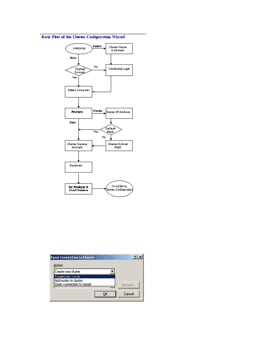
Configuring the Cluster Service
You must supply all initial cluster configuration information in the first installation phase. This is
accomplished using the Cluster Configuration Wizard.
As seen in the flow chart, the form (Create a new Cluster) and the Join (Add nodes) take a couple
different paths, but they have a few of the same pages. Namely, Credential Login, Analyze, and Re-
Analyze and Start Service are the same. There are minor differences in the following pages: Welcome,
Select Computer, and Cluster Service Account. In the next two sections of this lesson, you will step
through the wizard pages presented on each of these configuration paths. In the third section, after you
follow the step-through sections, this white paper describes in detail the Analyze, ,Re-Analyze and Start
Service pages, and what the information provided in these screens means.
Note During Cluster service configuration on node 1, you must turn off all other nodes. All shared
storage devices should be turned on.
To Configure the First Node
1.
Click Start, click All Programs, click Administrative Tools, and then click Cluster
Administrator.
2.
When prompted by the Open Connection to Cluster Wizard, click Create new cluster in the
Action drop-down list, as shown in Figure 9 below.
Figure 9 The Action drop-down list.
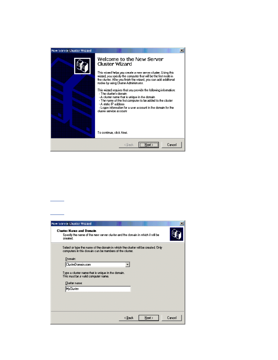
3.
Verify that you have the necessary prerequisites to configure the cluster, as shown in Figure 10
below. Click Next.
Figure 10 A list of prerequisites is part of the New Server Cluster Wizard Welcome page.
4.
Type a unique NetBIOS name for the cluster (up to 15 characters), and then click Next. In the
example shown in Figure 11 below, the cluster is named MyCluster.) Adherence to DNS naming
rules is recommended. For additional information, see the following articles in the Microsoft
Knowledge Base:
NetBIOS Suffixes (16th Character of the NetBIOS Name)
DNS Namespace Planning
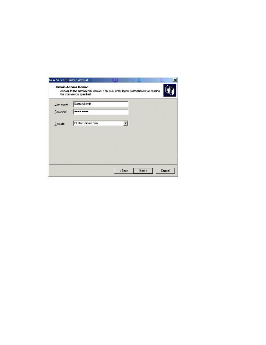
Figure 11 Adherence to DNS naming rules is recommended when naming the cluster.
5.
If you are logged on locally with an account that is not a Domain Account with Local
Administrative privileges, the wizard will prompt you to specify an account. This is not the account
the Cluster service will use to start.
Note If you have appropriate credentials, the prompt mentioned in step 5 and shown in Figure 12
below may not appear.
Figure 12 The New Server Cluster Wizard prompts you to specify an account.
6.
Because it is possible to configure clusters remotely, you must verify or type the name of the
server that is going to be used as the first node to create the cluster, as shown in Figure 13 below.
Click Next.
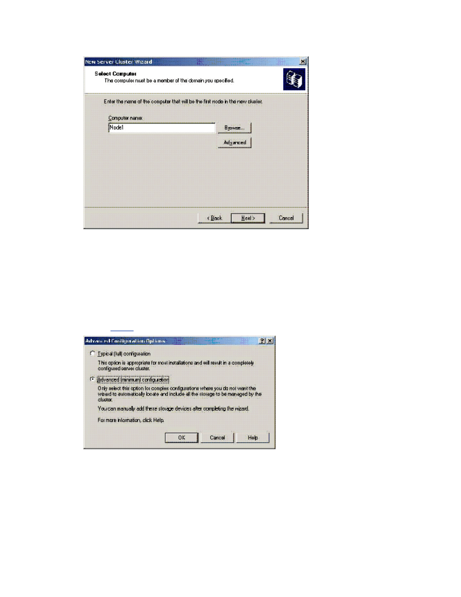
Figure 13 Select the name of the computer that will be the first node in the cluster.
Note The Install wizard verifies that all nodes can see the shared disks the same. In a
complex storage area network the target identifiers (TIDs) for the disks may sometimes be
different, and the Setup program may incorrectly detect that the disk configuration is not
valid for Setup. To work around this issue you can click the Advanced button, and then
click Advanced (minimum) configuration. For additional information, see the following
article in the Microsoft Knowledge Base:
Cluster Setup May Not Work When You Add Nodes
7.
Figure 14 below illustrates that the Setup process will now analyze the node for possible
hardware or software problems that may cause problems with the installation. Review any warnings
or error messages. You can also click the Details button to get detailed information about each one.
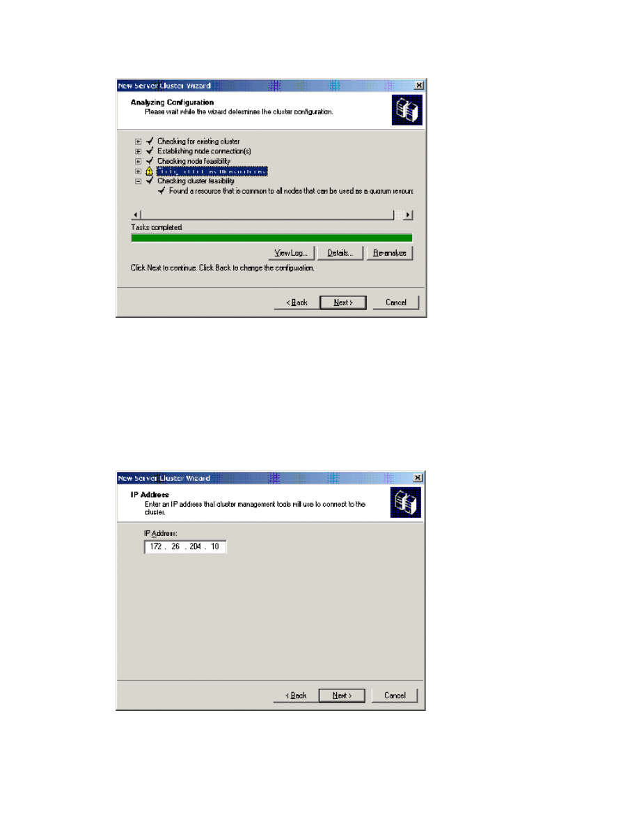
Figure 14 The Setup process analyzes the node for possible hardware or software
problems.
8.
Type the unique cluster IP address (in this example 172.26.204.10), and then click Next.
As shown in Figure 15 below, the New Server Cluster Wizard automatically associates the cluster IP
address with one of the public networks by using the subnet mask to select the correct network. The
cluster IP address should be used for administrative purposes only, and not for client connections.
Figure 15 The New Server Cluster Wizard automatically associates the cluster IP address
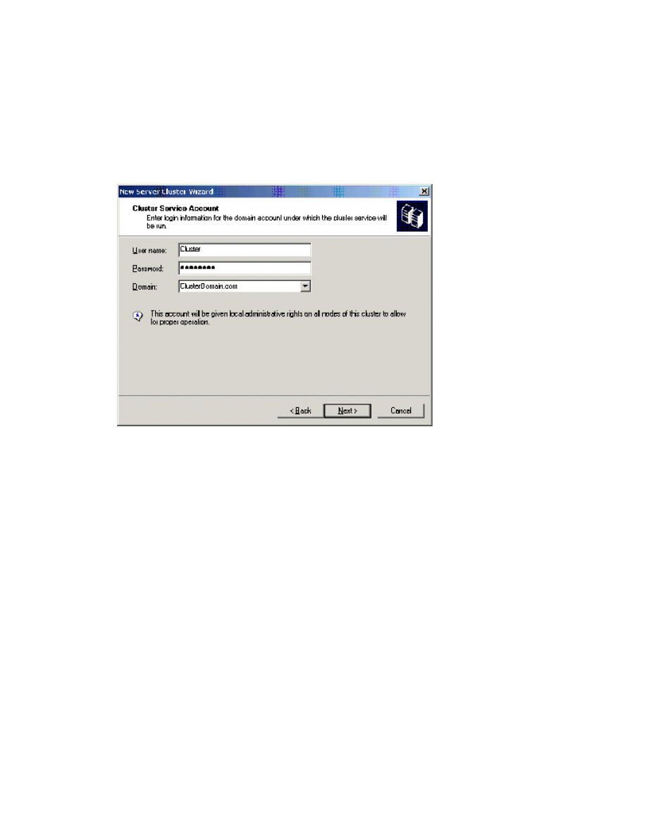
with one of the public networks.
9.
Type the user name and password of the cluster service account that was created during pre-
installation. (In the example in Figure 16 below, the user name is “Cluster”). Select the domain name
in the Domain drop-down list, and then click Next.
At this point, the Cluster Configuration Wizard validates the user account and password.
Figure 16 The wizard prompts you to provide the account that was created during pre-
installation.
10.
Review the Summary page, shown in Figure 17 below, to verify that all the information that is
about to be used to create the cluster is correct. If desired, you can use the quorum button to
change the quorum disk designation from the default auto-selected disk.
The summary information displayed on this screen can be used to reconfigure the cluster in the
event of a disaster recovery situation. It is recommended that you save and print a hard copy to
keep with the change management log at the server.
Note The Quorum button can also be used to specify a Majority Node Set (MNS) quorum
model. This is one of the major configuration differences when you create an MNS cluster
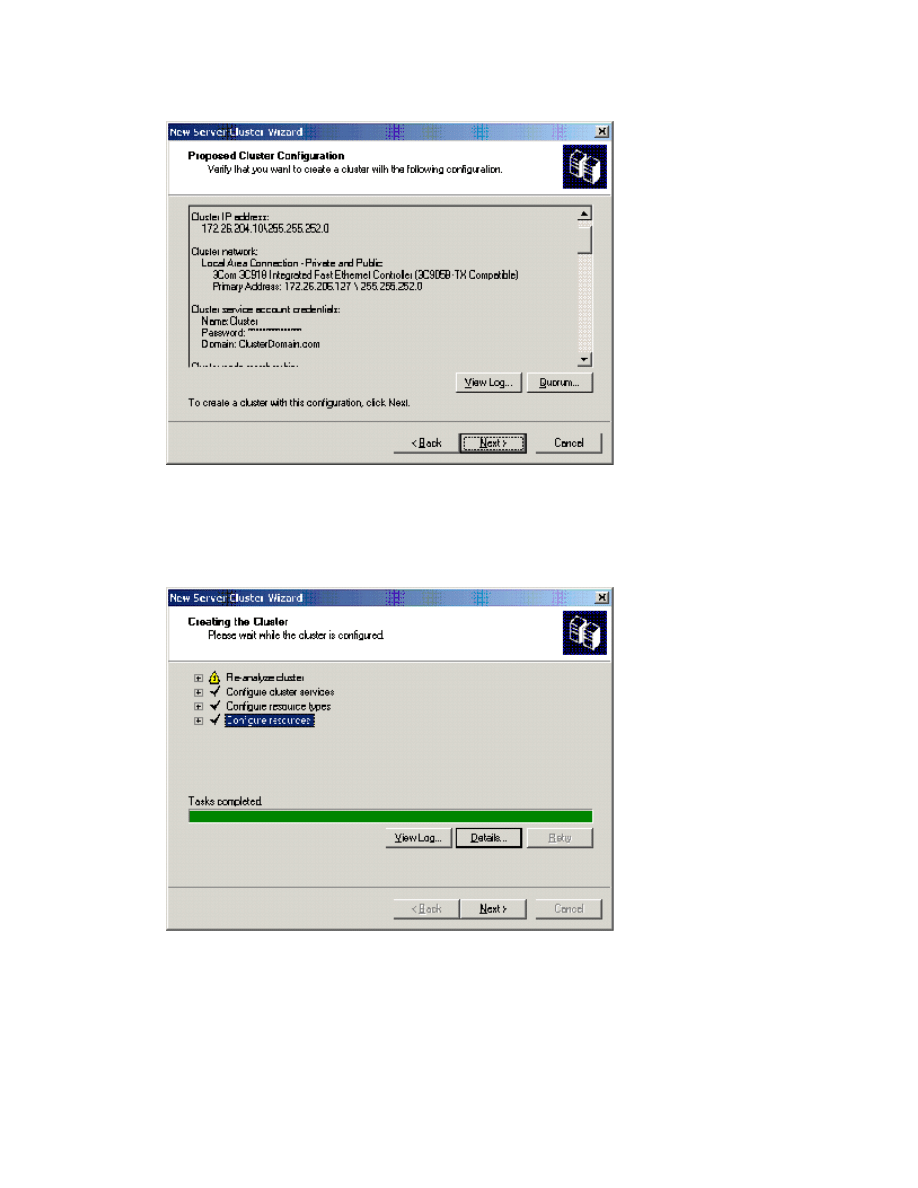
Figure 17 The Proposed Cluster Configuration page.
11.
Review any warnings or errors encountered during cluster creation. To do this, click the plus
signs to see more, and then click Next. Warnings and errors appear in the Creating the Cluster page
as shown in Figure 18.
Figure 18 Warnings and errors appear on the Creating the Cluster page.
12.
Click Finish to complete the installation. Figure 19 below illustrates the final step.
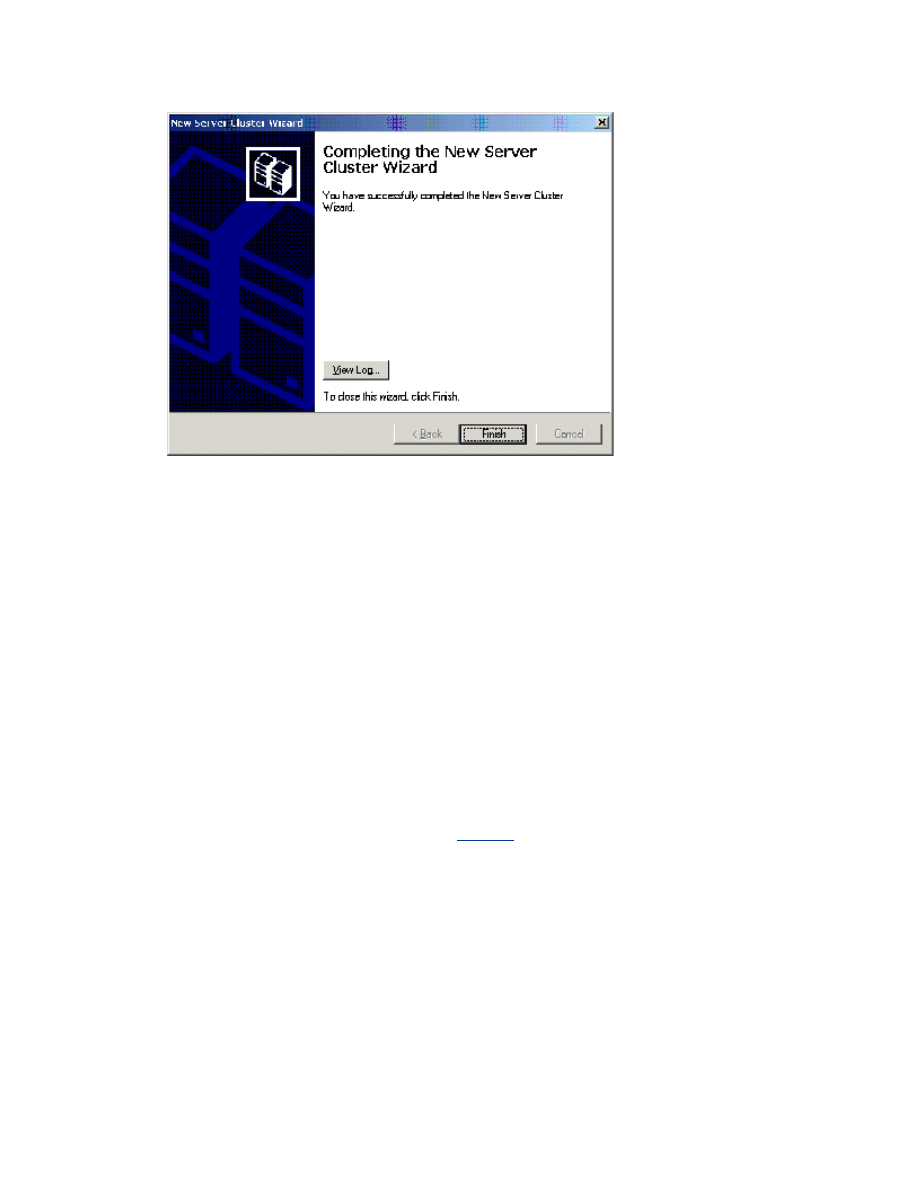
Figure 19 The final step in setting up a new server cluster.
Note To view a detailed summary, click the View Log button or view the text file stored in
the following location:
%SystemRoot%\System32\LogFiles\Cluster\ClCfgSrv.Log
Validating the Cluster Installation
Use the Cluster Administrator (CluAdmin.exe) to validate the cluster service installation on node 1.
To Validate the Cluster Installation
1.
Click Start, click Programs, click Administrative Tools, and then click Cluster
Administrator.
2.
Verify that all resources came online successfully, as shown in Figure 20 below.
If your browser does not support inline frames,
to view on a separate page.
Figure 20 The Cluster Administer verifies that all resources came online successfully.
Note As general rules, do not put anything in the cluster group, do not take anything out of the cluster
group, and do not use anything in the cluster group for anything other than cluster administration.
Configuring the Second Node
Installing the cluster service on the other nodes requires less time than on the first node. Setup configures
the cluster service network settings on the second node based on the configuration of the first node. You
can also add multiple nodes to the cluster at the same time, and remotely.
Note For this section, leave node 1 and all shared disks turned on. Then turn on all other nodes. The
cluster service will control access to the shared disks at this point to eliminate any chance of corrupting
the volume.
1.
Open Cluster Administrator on Node 1.
2.
Click File, click New, and then click Node.
3.
The Add Cluster Computers Wizard will start. Click Next.
4.
If you are not logged on with appropriate credentials, you will be asked to specify a domain
account that has administrative rights over all nodes in the cluster.
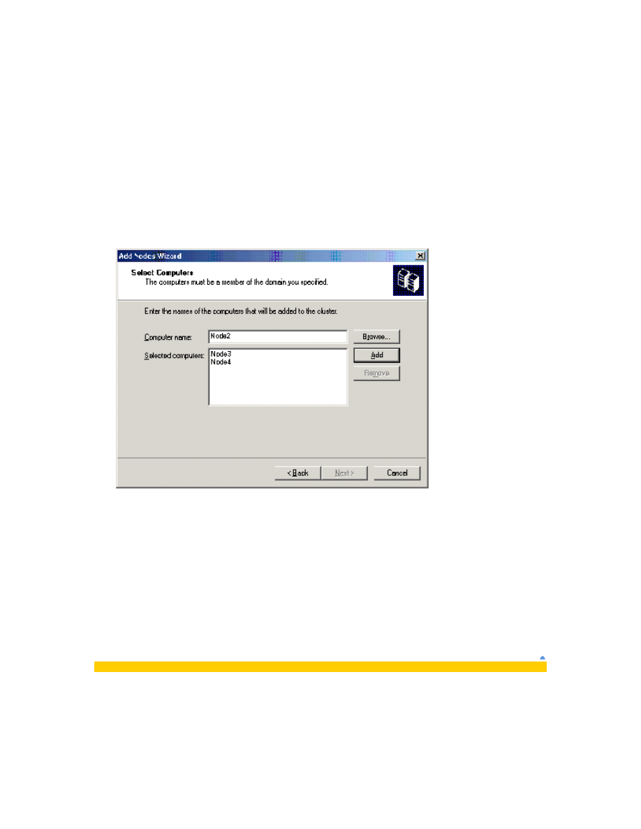
5.
Enter the machine name for the node you want to add to the cluster. Click Add. Repeat this step,
shown in Figure 21 below, to add all other nodes that you want. When you have added all nodes,
click Next.
Figure 21 Adding nodes to the cluster.
6.
The Setup wizard will perform an analysis of all the nodes to verify that they are configured
properly.
7.
Type the password for the account used to start the cluster service.
8.
Review the summary information that is displayed for accuracy. The summary information will be
used to configure the other nodes when they join the cluster.
9.
Review any warnings or errors encountered during cluster creation, and then click Next.
10.
Click Finish to complete the installation.
Post-Installation Configuration
Heartbeat Configuration

Now that the networks have been configured correctly on each node and the Cluster service has been
configured, you need to configure the network roles to define their functionality within the cluster. Here is
a list of the network configuration options in Cluster Administrator:
•
Enable for cluster use: If this check box is selected, the cluster service uses this network. This
check box is selected by default for all networks.
•
Client access only (public network): Select this option if you want the cluster service to use
this network adapter only for external communication with other clients. No node-to-node
communication will take place on this network adapter.
•
Internal cluster communications only (private network): Select this option if you want the
cluster service to use this network only for node-to-node communication.
•
All communications (mixed network): Select this option if you want the cluster service to use
the network adapter for node-to-node communication and for communication with external clients.
This option is selected by default for all networks.
This white paper assumes that only two networks are in use. It explains how to configure these networks
as one mixed network and one private network. This is the most common configuration. If you have
available resources, two dedicated redundant networks for internal-only cluster communication are
recommended.
To Configure the Heartbeat
1.
Start Cluster Administrator.
2.
In the left pane, click Cluster Configuration, click Networks, right-click Private, and then click
Properties.
3.
Click Internal cluster communications only (private network), as shown in Figure 22
below.
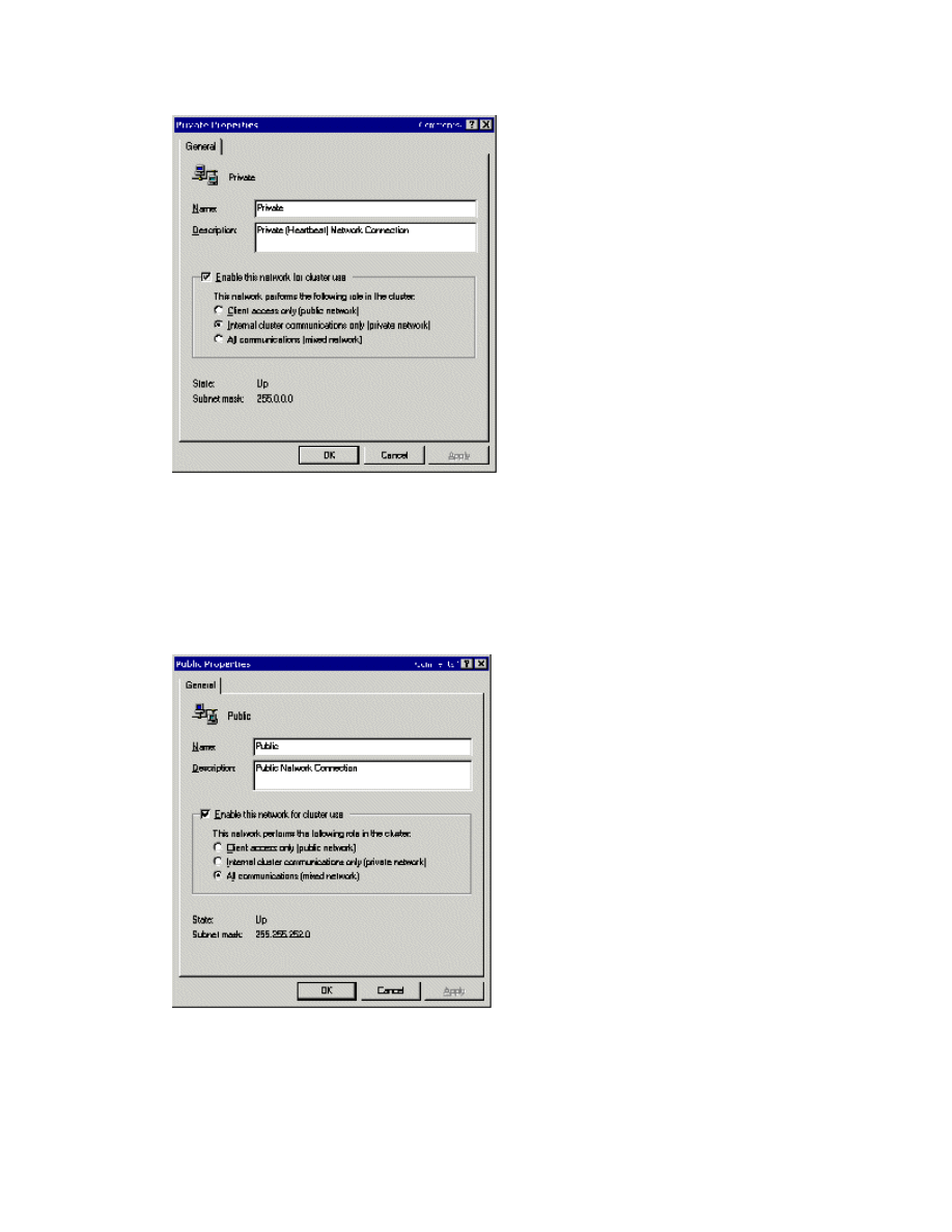
Figure 22 Using Cluster Administrator to configure the heartbeat.
4.
Click OK.
5.
Right-click Public, and then click Properties (shown in Figure 23 below).
6.
Click to select the Enable this network for cluster use check box.
7.
Click the All communications (mixed network) option, and then click OK.
Figure 23 The Public Properties dialog box.
Heartbeat Adapter Prioritization
After configuring the role of how the cluster service will use the network adapters, the next step is to
prioritize the order in which they will be used for intra-cluster communication. This is applicable only if two
or more networks were configured for node-to-node communication. Priority arrows on the right side of
the screen specify the order in which the cluster service will use the network adapters for communication
between nodes. The cluster service always attempts to use the first network adapter listed for remote
procedure call (RPC) communication between the nodes. Cluster service uses the next network adapter in
the list only if it cannot communicate by using the first network adapter.
1.
Start Cluster Administrator.
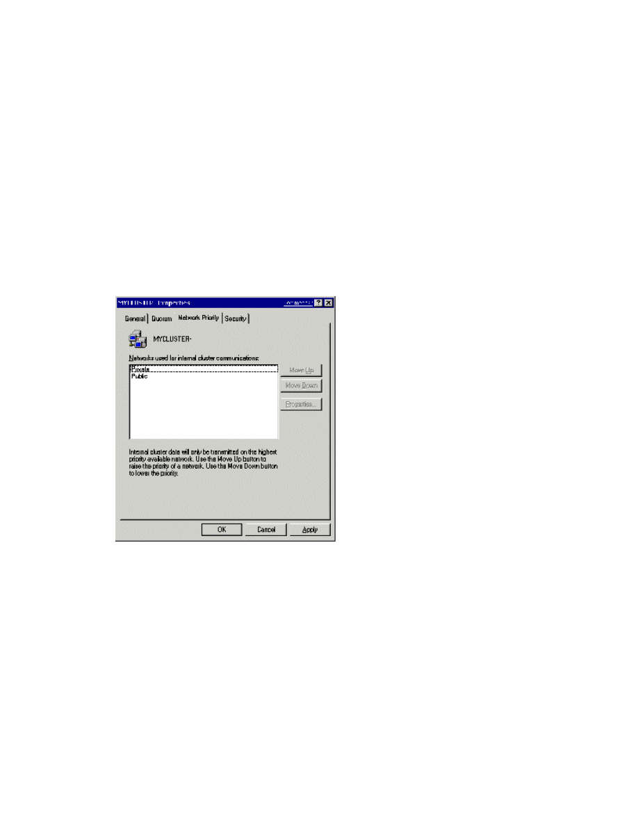
2.
In the left pane, right-click the cluster name (in the upper left corner), and then click
Properties.
3.
Click the Network Priority tab, as shown in Figure 24 below.
Figure 24 The Network Priority tab in Cluster Administrator.
4.
Verify that the Private network is listed at the top. Use the Move Up or Move Down buttons to
change the priority order.
5.
Click OK.
Configuring Cluster Disks
•
Start Cluster Administrator, right-click any disks that you want to remove from the cluster, and
then click Delete.
Note By default, all disks not residing on the same bus as the system disk will have Physical Disk
Resources created for them, and will be clustered. Therefore, if the node has multiple buses, some disks
may be listed that will not be used as shared storage, for example, an internal SCSI drive. Such disks
should be removed from the cluster configuration. If you plan to implement Volume Mount points for some
disks, you may want to delete the current disk resources for those disks, delete the drive letters, and then
create a new disk resource without a drive letter assignment.
Quorum Disk Configuration
The Cluster Configuration Wizard automatically selects the drive that is to be used as the quorum device.
It will use the smallest partition that is larger then 50 MB. You may want to change the automatically
selected disk to a dedicated disk that you have designated for use as the quorum.
To Configure the Quorum Disk
1.
Start Cluster Administrator (CluAdmin.exe).
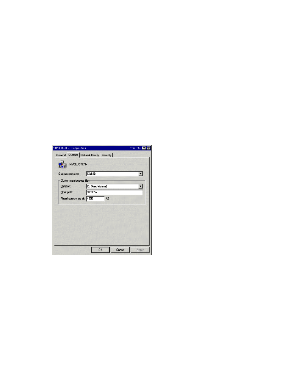
2.
Right-click the cluster name in the upper-left corner, and then click Properties.
3.
Click the Quorum tab.
4.
In the Quorum resource list box, select a different disk resource. In Figure 25 below, Disk Q is
selected in the Quorum resource list box.
Figure 25 The Quorum resource list box.
5.
If the disk has more than one partition, click the partition where you want the cluster-specific
data to be kept, and then click OK.
For additional information, see the following article in the Microsoft Knowledge Base:
How to Change Quorum Disk Designation
Creating a Boot Delay
In a situation where all the cluster nodes boot up and attempt to attach to the quorum resource at the

same time, the Cluster service may fail to start. For example, this may occur when power is restored to all
nodes at the exact same time after a power failure. To avoid such a situation, increase or decrease the
Time to Display list of operating systems setting. To find this setting, click Start, point to My
Computer, right-click My Computer, and then click Properties. Click the Advanced tab, and then click
Settings under Startup And Recovery.
Test Installation
There are several methods for verifying a cluster service installation after the Setup process is complete.
These include:
•
Cluster Administrator: If installation was completed only on node 1, start Cluster
Administrator, and then attempt to connect to the cluster. If a second node was installed, start
Cluster Administrator on either node, connect to the cluster, and then verify that the second node is
listed.
•
Services Applet: Use the services snap-in to verify that the cluster service is listed and started.
•
Event Log: Use the Event Viewer to check for ClusSvc entries in the system log. You should see
entries confirming that the cluster service successfully formed or joined a cluster.
•
Cluster service registry entries: Verify that the cluster service installation process wrote the
correct entries to the registry. You can find many of the registry settings under
HKEY_LOCAL_MACHINE\Cluster
•
Click Start, click Run, and then type the Virtual Server name. Verify that you can connect and
see resources.
Test Failover
To Verify that Resources will Failover
1.
Click Start, click Programs, click Administrative Tools, and then click Cluster
Administrator, as shown in Figure 26 below.
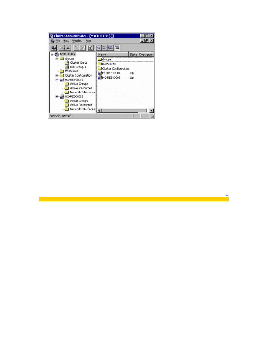
Figure 26 The Cluster Administrator window.
2.
Right-click the Disk Group 1 group, and then click Move Group. The group and all its resources
will be moved to another node. After a short period of time, the Disk F: G: will be brought online on
the second node. Watch the window to see this shift. Quit Cluster Administrator.
Congratulations! You have completed the configuration of the cluster service on all nodes. The server
cluster is fully operational. You are now ready to install cluster resources such as file shares, printer
spoolers, cluster aware services like Distributed Transaction Coordinator, DHCP, WINS, or cluster-aware
programs such as Exchange Server or SQL Server.
Appendix
Advanced Testing
Now that you have configured your cluster and verified basic functionality and failover, you may want to
conduct a series of failure scenario tests that will demonstrate expected results and ensure the cluster will
respond correctly when a failure occurs. This level of testing is not required for every implementation, but
may be insightful if you are new to clustering technology and are unfamiliar how the cluster will respond
or if you are implementing a new hardware platform in your environment. The expected results listed are
for a clean configuration of the cluster with default settings, this does not take into consideration any user
customization of the failover logic. This is not a complete list of all tests, nor should successfully
completing these tests be considered “certified” or ready for production. This is simply a sample list of
some tests that can be conducted. For additional information, see the following article in the Microsoft
Knowledge Base:

Failover/Failback Policies on Microsoft Cluster Server
Test: Start Cluster Administrator, right-click a resource, and then click “Initiate Failure”. The resource
should go into an failed state, and then it will be restarted and brought back into an online state on that
node.
Expected Result: Resources should come back online on the same node
Test: Conduct the above “Initiate Failure” test three more times on that same resource. On the fourth
failure, the resources should all failover to another node in the cluster.
Expected Result: Resources should failover to another node in the cluster
Test: Move all resources to one node. Start Computer Management, and then click Services under
Services and Applications. Stop the Cluster service. Start Cluster Administrator on another node and
verify that all resources failover and come online on another node correctly.
Expected Result: Resources should failover to another node in the cluster
Test: Move all resources to one node. On that node, click Start, and then click Shutdown. This will turn
off that node. Start Cluster Administrator on another node, and then verify that all resources failover and
come online on another node correctly.
Expected Result: Resources should failover to another node in the cluster
Test: Move all resources to one node, and then press the power button on the front of that server to turn
it off. If you have an ACPI compliant server, the server will perform an “Emergency Shutdown” and turn
off the server. Start Cluster Administrator on another node and verify that all resources failover and come
online on another node correctly. For additional information about an Emergency Shutdown, see the
following articles in the Microsoft Knowledge Base:
HOW TO: Perform an Emergency Shutdown in Windows Server 2003
Power Button on ACPI Computer May Force an Emergency Shutdown
Expected Result: Resources should failover to another node in the cluster
Warning Performing the Emergency Shutdown test may cause data corruption and data loss. Do not
conduct this test on a production server
Test: Move all resources to one node, and then pull the power cables from that server to simulate a hard

failure. Start Cluster Administrator on another node, and then verify that all resources failover and come
online on another node correctly
Expected Result: Resources should failover to another node in the cluster
Warning Performing the hard failure test may cause data corruption and data loss. This is an extreme
test. Make sure you have a backup of all critical data, and then conduct the test at your own risk. Do not
conduct this test on a production server
Test: Move all resources to one node, and then remove the public network cable from that node. The IP
Address resources should fail, and the groups will all failover to another node in the cluster. For additional
information , see the following articles in the Microsoft Knowledge Base:
Network Failure Detection and Recovery in Windows Server 2003 Clusters
Expected Result: Resources should failover to another node in the cluster
Test: Remove the network cable for the Private heartbeat network. The heartbeat traffic will failover to
the public network, and no failover should occur. If failover occurs, please see the “Configuring the Private
Network Adaptor” section in earlier in this document
Expected Result: There should be no failures or resource failovers
SCSI Drive Installations
This appendix is provided as a generic set of instructions for SCSI drive installations. If the SCSI hard disk
vendor’s instructions conflict with the instructions here, always follow the instructions supplied by the
vendor.
The SCSI bus listed in the hardware requirements must be configured prior to cluster service installation.
Configuration applies to:
•
The SCSI devices.
•
The SCSI controllers and the hard disks so that they work properly on a shared SCSI bus.
•
Properly terminating the bus. The shared SCSI bus must have a terminator at each end of the
bus. It is possible to have multiple shared SCSI buses between the nodes of a cluster.
In addition to the information on the following pages, refer to documentation from the manufacturer of
your SCSI device or to the SCSI specifications, which can be ordered from the American National
Standards Institute (ANSI). The
includes a catalog that can be searched for the SCSI
specifications.

Configuring the SCSI Devices
Each device on the shared SCSI bus must have a unique SCSI identification number. Because most SCSI
controllers default to SCSI ID 7, configuring the shared SCSI bus includes changing the SCSI ID number
on one controller to a different number, such as SCSI ID 6. If there is more than one disk that will be on
the shared SCSI bus, each disk must have a unique SCSI ID number.
Terminating the Shared SCSI Bus
There are several methods for terminating the shared SCSI bus. They include:
•
SCSI controllers
SCSI controllers have internal soft termination that can be used to terminate the bus, however this
method is not recommended with the cluster server. If a node is turned off with this configuration,
the SCSI bus will be terminated improperly and will not operate correctly.
•
Storage enclosures
Storage enclosures also have internal termination, which can be used to terminate the SCSI bus if
the enclosure is at the end of the SCSI bus. This should be turned off.
•
Y cables
Y cables can be connected to devices if the device is at the end of the SCSI bus. An external active
terminator can then be attached to one branch of the Y cable in order to terminate the SCSI bus.
This method of termination requires either disabling or removing any internal terminators that the
device may have.
Figure 27 outlines how a SCSI cluster should be physically connected.
If your browser does not support inline frames,
to view on a separate page.
Figure 27 A diagram of a SCSI cluster hardware configuration.
Note Any devices that are not at the end of the shared bus must have their internal termination
disabled. Y cables and active terminator connectors are the recommended termination methods because
they will provide termination even when a node is not online.
Storage Area Network Considerations
There are two supported methods of Fibre Channel-based storage in a Windows Server 2003 server
cluster: arbitrated loops and switched fabric.
Important When evaluating both types of Fibre Channel implementation, read the vendor’s
documentation and be sure you understand the specific features and restrictions of each.
Although the term Fibre Channel implies the use of fiber-optic technology, copper coaxial cable is also
allowed for interconnects.
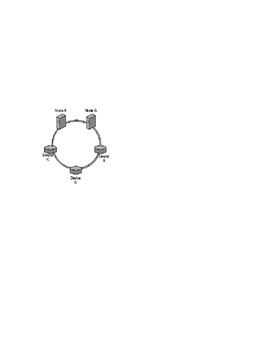
Arbitrated Loops (FC-AL)
A Fibre Channel arbitrated loop (FC-AL) is a set of nodes and devices connected into a single loop. FC-AL
provides a cost-effective way to connect up to 126 devices into a single network. As with SCSI, a
maximum of two nodes is supported in an FC-AL server cluster configured with a hub. An FC-AL is
illustrated in 28.
Figure 28 FC-AL Connection
FC-ALs provide a solution for two nodes and a small number of devices in relatively static configurations.
All devices on the loop share the media, and any packet traveling from one device to another must pass
through all intermediate devices.
If your high-availability needs can be met with a two-node server cluster, an FC-AL deployment has
several advantages:
•
The cost is relatively low.
•
Loops can be expanded to add storage (although nodes cannot be added).
•
Loops are easy for Fibre Channel vendors to develop.
The disadvantage is that loops can be difficult to deploy in an organization. Because every device on the
loop shares the media, overall bandwidth in the cluster is lowered. Some organizations might also be
unduly restricted by the 126-device limit.

Switched Fabric (FC-SW)
For any cluster larger than two nodes, a switched Fibre Channel switched fabric (FC-SW) is the only
supported storage technology. In an FC-SW, devices are connected in a many-to-many topology using
Fibre Channel switches (illustrated in Figure 29).
If your browser does not support inline frames,
to view on a separate page.
Figure 29 FC-SW Connection
When a node or device communicates with another node or device in an FC-SW, the source and target set
up a point-to-point connection (similar to a virtual circuit) and communicate directly with each other. The
fabric itself routes data from the source to the target. In an FC-SW, the media is not shared. Any device
can communicate with any other device, and communication occurs at full bus speed. This is a fully
scalable enterprise solution and, as such, is highly recommended for deployment with server clusters.
FC-SW is the primary technology employed in SANs. Other advantages of FC-SW include ease of
deployment, the ability to support millions of devices, and switches that provide fault isolation and
rerouting. Also, there is no shared media as there is in FC-AL, allowing for faster communication.
However, be aware that FC-SWs can be difficult for vendors to develop, and the switches can be
expensive. Vendors also have to account for interoperability issues between components from different
vendors or manufacturers.
Using SANs with Server Clusters
For any large-scale cluster deployment, it is recommended that you use a SAN for data storage. Smaller
SCSI and stand-alone Fibre Channel storage devices work with server clusters, but SANs provide superior
fault tolerance.
A SAN is a set of interconnected devices (such as disks and tapes) and servers that are connected to a
common communication and data transfer infrastructure (FC-SW, in the case of Windows Server 2003
clusters). A SAN allows multiple server access to a pool of storage in which any server can potentially
access any storage unit.
The information in this section provides an overview of using SAN technology with your Windows
Server 2003 clusters. For additional information about deploying server clusters on SANs, see the
Windows Clustering: Storage Area Networks link on the
at
http://www.microsoft.com/windows/reskits/webresources/
.

Note Vendors that provide SAN fabric components and software management tools have a wide range of
tools for setting up, configuring, monitoring, and managing the SAN fabric. Contact your SAN vendor for
details about your particular SAN solution.
SCSI Resets
Earlier versions of Windows server clusters presumed that all communications to the shared disk should
be treated as an isolated SCSI bus. This behavior may be somewhat disruptive, and it does not take
advantage of the more advanced features of Fibre Channel to both improve arbitration performance and
reduce disruption.
One key enhancement in Windows Server 2003 is that the Cluster service issues a command to break a
RESERVATION, and the StorPort driver can do a targeted or device reset for disks that are on a Fibre
Channel topology. In Windows 2000 server clusters, an entire bus-wide SCSI RESET is issued. This causes
all devices on the bus to be disconnected. When a SCSI RESET is issued, a lot of time is spent resetting
devices that may not need to be reset, such as disks that the CHALLENGER node may already own.
Resets in Windows 2003 occur in the following order:
1.
1. Targeted logical unit number (LUN)
2.
2. Targeted SCSI ID
3.
3. Entire bus-wide SCSI RESET
Note Targeted resets require functionality in the host bus adapter (HBA) drivers. The driver must be
written for StorPort and not SCSIPort. Drivers that use SCSIPort will use the Challenge and Defense the
same as it is currently in Windows 2000. Contact the manufacturer of the HBA to determine if it supports
StorPort.
SCSI Commands
The Cluster service uses the following SCSI commands:
•
SCSI reserve: This command is issued by a host bus adapter or controller to maintain ownership
of a SCSI device. A device that is reserved refuses all commands from all other host bus adapters
except the one that initially reserved it, the initiator. If a bus-wide SCSI reset command is issued,
loss of reservation occurs.
•
SCSI release: This command is issued by the owning host bus adapter; it frees a SCSI device for
another host bus adapter to reserve.
•
SCSI reset: This command breaks the reservation on a target device. This command is
sometimes referred to globally as a "bus reset."
The same control codes are used for Fibre Channel as well. These parameters are defined in this partner
article:

How the Cluster Service Takes Ownership of a Disk on the Shared Bus
Supported Fibre Channel Configurations
The following sections provide an overview of SAN concepts that directly affect a server cluster
deployment.
HBAs
Host bus adapters (HBAs) are the interface cards that connect a cluster node to a SAN, similar to the way
that a network adapter connects a server to a typical Ethernet network. HBAs, however, are more difficult
to configure than network adapters (unless the HBAs are preconfigured by the SAN vendor). All HBAs in all
nodes should be identical and be at the same driver and firmware revision
Zoning and LUN Masking
Zoning and LUN masking are fundamental to SAN deployments, particularly as they relate to a Windows
Server 2003 cluster deployment.
Zoning
Many devices and nodes can be attached to a SAN. With data stored in a single cloud, or storage entity, it
is important to control which hosts have access to specific devices. Zoning allows administrators to
partition devices in logical volumes and thereby reserve the devices in a volume for a server cluster. That
means that all interactions between cluster nodes and devices in the logical storage volumes are isolated
within the boundaries of the zone; other noncluster members of the SAN are not affected by cluster
activity.
Figure 30 is a logical depiction of two SAN zones (Zone A and Zone B), each containing a storage
controller (S1and S2, respectively).
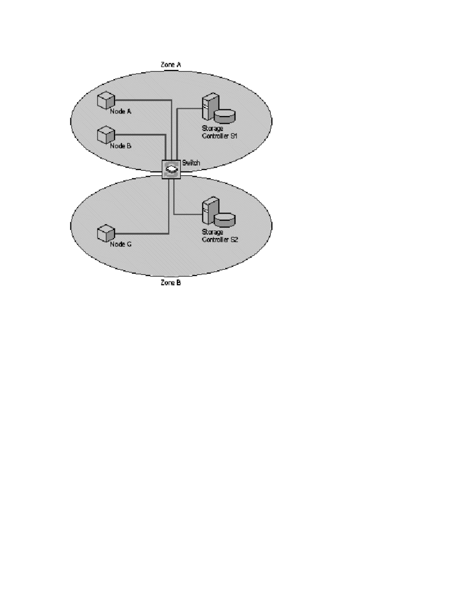
Figure 30 Zoning
In this implementation, Node A and Node B can access data from the storage controller S1, but Node C
cannot. Node C can access data from storage controller S2.
Zoning needs to be implemented at the hardware level (with the controller or switch) and not through
software. The primary reason is that zoning is also a security mechanism for a SAN-based cluster, because
unauthorized servers cannot access devices inside the zone (access control is implemented by the
switches in the fabric, so a host adapter cannot gain access to a device for which it has not been
configured). With software zoning, the cluster would be left unsecured if the software component failed.
In addition to providing cluster security, zoning also limits the traffic flow within a given SAN environment.
Traffic between ports is routed only to segments of the fabric that are in the same zone.
LUN Masking
A LUN is a logical disk defined within a SAN. Server clusters see LUNs and think they are physical disks.
LUN masking, performed at the controller level, allows you to define relationships between LUNs and
cluster nodes. Storage controllers usually provide the means for creating LUN-level access controls that
allow access to a given LUN to one or more hosts. By providing this access control at the storage

controller, the controller itself can enforce access policies to the devices.
LUN masking provides more granular security than zoning, because LUNs provide a means for zoning at
the port level. For example, many SAN switches allow overlapping zones, which enable a storage
controller to reside in multiple zones. Multiple clusters in multiple zones can share the data on those
controllers. Figure 31 illustrates such a scenario.
If your browser does not support inline frames,
to view on a separate page.
Figure 31 Storage Controller in Multiple Zones
LUNs used by Cluster A can be masked, or hidden, from Cluster B so that only authorized users can access
data on a shared storage controller.
Requirements for Deploying SANs with Windows Server 2003 Clusters
The following list highlights the deployment requirements you need to follow when using a SAN storage
solution with your server cluster. For a white paper that provides more complete information about using
SANs with server clusters, see the Windows Clustering: Storage Area Networks link on the
at
http://www.microsoft.com/windows/reskits/webresources/
Each cluster on a SAN must be deployed in its own zone. The mechanism the cluster uses to protect
access to the disks can have an adverse effect on other clusters that are in the same zone. By using
zoning to separate the cluster traffic from other cluster or noncluster traffic, there is no chance of
interference.
All HBAs in a single cluster must be the same type and have the same firmware version. Many storage and
switch vendors require that all HBAs on the same zone—and, in some cases, the same fabric—share these
characteristics.
All storage device drivers and HBA device drivers in a cluster must have the same software version.
Never allow multiple nodes access to the same storage devices unless they are in the same cluster.
Never put tape devices into the same zone as cluster disk storage devices. A tape device could
misinterpret a bus rest and rewind at inappropriate times, such as during a large backup.
Guidelines for Deploying SANs with Windows Server 2003 Server Clusters
In addition to the SAN requirements discussed in the previous section, the following practices are highly

recommended for server cluster deployment:
In a highly available storage fabric, you need to deploy clustered servers with multiple HBAs. In these
cases, always load the multipath driver software. If the I/O subsystem sees two HBAs, it assumes they
are different buses and enumerates all the devices as though they were different devices on each bus. The
host, meanwhile, is seeing multiple paths to the same disks. Failure to load the multipath driver will
disable the second device because the operating system sees what it thinks are two independent disks
with the same signature.
Do not expose a hardware snapshot of a clustered disk back to a node in the same cluster. Hardware
snapshots must go to a server outside the server cluster. Many controllers provide snapshots at the
controller level that can be exposed to the cluster as a completely separate LUN. Cluster performance is
degraded when multiple devices have the same signature. If the snapshot is exposed back to the node
with the original disk online, the I/O subsystem attempts to rewrite the signature. However, if the
snapshot is exposed to another node in the cluster, the Cluster service does not recognize it as a different
disk and the result could be data corruption. Although this is not specifically a SAN issue, the controllers
that provide this functionality are typically deployed in a SAN environment.
For additional information, see the following articles in the Microsoft Knowledge Base:
Cluster Service Improvements for Storage Area Networks
Support for Multiple Clusters Attached to the Same SAN Device
Windows Clustering and Geographically Separate Sites
Related Links
See the following resources for further information:
•
Microsoft Cluster Service Installation Resources at
http://support.microsoft.com/?id=259267
•
Quorum Drive Configuration Information at
http://support.microsoft.com/?id=280345
•
Recommended Private "Heartbeat" Configuration on Cluster Server at
http://support.microsoft.com/?id=258750
•
Network Failure Detection and Recovery in a Server Cluster at

http://support.microsoft.com/?id=242600
•
How to Change Quorum Disk Designation at
http://support.microsoft.com/?id=280353
•
Microsoft Windows Clustering: Storage Area Networks at
http://www.microsoft.com/windows.netserver/techinfo/overview/san.mspx
•
Geographically Dispersed Clusters in Windows Server 2003 at
http://www.microsoft.com/windows.netserver/techinfo/overview/clustergeo.mspx
•
Server Cluster Network Requirements and Best Practices at
http://www.microsoft.com/technet/prodtechnol/windowsserver2003/maintain/operate/clstntbp.asp
For the latest information about Windows Server 2003, see the Windows 2003 Server Web site at
http://www.microsoft.com/windowsserver2003/default.mspx
This is a preliminary document and may be changed substantially prior to final commercial release of the
software described herein.
The information contained in this document represents the current view of Microsoft Corporation on the
issues discussed as of the date of publication. Because Microsoft must respond to changing market
conditions, it should not be interpreted to be a commitment on the part of Microsoft, and Microsoft cannot
guarantee the accuracy of any information presented after the date of publication.
This document is for informational purposes only. MICROSOFT MAKES NO WARRANTIES, EXPRESS OR
IMPLIED, AS TO THE INFORMATION IN THIS DOCUMENT.
Complying with all applicable copyright laws is the responsibility of the user. Without limiting the rights
under copyright, no part of this document may be reproduced, stored in or introduced into a retrieval
system, or transmitted in any form or by any means (electronic, mechanical, photocopying, recording, or
otherwise), or for any purpose, without the express written permission of Microsoft Corporation.
Microsoft may have patents, patent applications, trademarks, copyrights, or other intellectual property
rights covering subject matter in this document. Except as expressly provided in any written license
agreement from Microsoft, the furnishing of this document does not give you any license to these patents,
trademarks, copyrights, or other intellectual property.
© 2003 Microsoft Corporation. All rights reserved.
Microsoft, Windows, the Windows logo, and Windows NT are either registered trademarks or trademarks
of Microsoft Corporation in the United States and/or other countries.

The names of actual companies and products mentioned herein may be the trademarks of their respective
owners.
Wyszukiwarka
Podobne podstrony:
Guide To Budgets And Financial Management
Guide to Selection and Use of D Nieznany
THE ULTIMATE?GINNER'S GUIDE TO HACKING AND PHREAKING
Beyond Fear A Toltec Guide to Freedom and JoyThe Teachings of Don Miguel Ruiz by don Miguel Ruiz 5
THE ONE MINUTE GUIDE To Prosperity and Enlightenment Sri Siva
104 A Guide to Buying and Selecting Lumber
Terry Anderson, Laura E Huggins Property Rights, A Practical Guide to Freedom and Prosperity (2003)
THE ONE MINUTE GUIDE To Prosperity and Enlightenment Sri Siva
Guide To Budgets And Financial Management Margaret J Barr
GERMAN TOOL AND BLADE MAKERS A guide to manufacturers and distributors, their trademarks and brand n
Eason, Cassandra A Practival Guide to Witchcraft and Magic
Carol Dunlop Fiji Islands Yachting The Official Guide to Sailing and Cruising in the Fiji Islands
Windows 10 A Complete User Guide Learn How To Choose And Install Updates In Your Windows 10!
Herbs for Sports Performance, Energy and Recovery Guide to Optimal Sports Nutrition
Guide to the properties and uses of detergents in biology and biochemistry
A Guide to the Law and Courts in the Empire
więcej podobnych podstron