15010
Issue 03
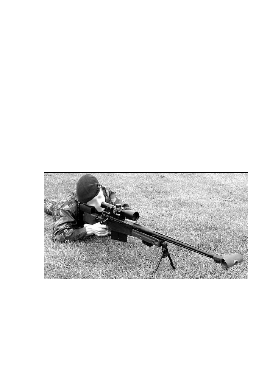
AW50 Anti Material Sniper Rifle
0.50 Calibre
&
Telescopic Sight
SuB 3-12x50 MKII 0.2 MRAD
User Manual
Published By Accuracy International Limited

UK & Rest Of World (Excluding USA)
Accuracy International Ltd.
P.O. Box 81
Portsmouth
Hampshire
PO3 5SJ
United Kingdom
Tel: +44 (0)23 9267 1225
Fax: +44 (0)23 9269 1852
Email:
precision@accint.org
USA Only
Accuracy International North America
P.O. Box 5267
Oak Ridge
TN 37831
USA
Tel: (865) 482-0330
Fax: (865) 482-0336
Email:
AINA@accuracyinternational.org

Accuracy International Ltd.
1
Contents
Page
1.0
Introduction
4
1.1
What's Covered Within This Manual
4
1.2
Accuracy International
5
1.3
General Description – Rifle
5
2.0
Technical Specification – Rifle
6
3.0
Top Level GA/Parts Identification
7
4.0
Safety
8
4.1
General
8
4.2
Safety Features
8
4.3
Firing Pin Cocking Indicator
9
4.4
Safe Handling Instructions
10
4.5
Checking That The Rifle Is Unloaded
11
4.6
Checking That The Bore Is Free Of Obstructions
11
4.7
Safety Lever Operation
12
4.8
Checking The Firing Pin’s Safe Operation
12
5.0
Operating Instructions – Rifle
13
5.1
Assembling The Rifle
13
5.2
Unfolding & Folding The Stock
13
5.3
Fitting & Removing The Bipod
14
5.4
Fitting & Removal Of The Hand Stop/Bipod Mount
(Accessory, where ordered)
15
5.5
Fitting & Removal Of The Scope/Mount
(Accessory, where ordered)
16
5.6
Fitting & Removal Of The Bolt
18
5.7
Insertion & Removal Of The Magazine
19
5.8
Setting Up The Rifle
20
5.9
Holding The Rifle
20
5.10 Bipod Adjustment
21
5.11 Third Leg Adjustment
21
5.12 Preparing To Fire The Rifle
22
5.13 Loading
22
5.14 Firing & Operating The Bolt
23
5.15 Reloading
24
5.16 Unloading
24
5.17 Unloading A Live Cartridge
24
5.18 Zeroing The Rifle To A Telescopic Sight
26
5.19 Iron Sights
(Accessory, where ordered)
28
5.20 Fitting & Removing The Iron Sights
28
5.21 Zeroing The Rifle To The Iron Sights
29
5.22 Disassembling The Rifle
30
5.23 Stripping The Magazine
30
5.24 Tests After Reassembly
32

AW50 Users Manual
2
Page
6.0
User Maintenance – Rifle
33
6.1
General
33
6.2
Cleaning & Lubricating Before Firing
33
6.3
Cleaning The Barrel & Chamber Before Firing
34
6.4
Cleaning & Lubricating After Firing
36
6.5
To Clean Heavy Copper Fouling
36
7.0
Recommended Lubricates & Cleaning Solutions
37
8.0
Operating Instructions – Telescope
(Accessory, where ordered)
38
8.1
General Description – Telescope
38
8.2
AI Reticule
39
8.3
Eye Relief
41
8.4
Eye Relief Adjustment
41
8.5
Eyepiece Dioptre Adjustment
42
8.6
Elevation Adjustment
42
8.7
Windage Adjustment
42
8.8
Parallax Adjustment
42
9.0
User Maintenance – Telescope
43
9.1
General
43
9.2
Cleaning The Telescope
43
10.0 Accuracy & Ammunition
44
11.0 User Tips
44
12.0 Customer Communication
45
13.0 Shooting Log
46

Accuracy International Ltd.
3
Illustrations
Fig.
Page
01
General Arrangement/Parts Identification
7
02
Cocking Piece Indicator – Cocked
9
03
Cocking Piece Indicator – Fired
9
04
Bipod
14
05
Fitting & Removal Of The Bipod
14
06
Fitting & Removal Of The Hand Stop/Bipod Mount
15
07
Scope Mount
16
08
Fitting The Scope Mount Onto The Rail
16
09
Fitting & Removal Of The Bolt
18
10
Setting Up The Rifle
20
11
Third Leg Adjustment
21
12
Iron Sights – Rear Sight
28
13
Iron Sights – Fore Sight
28
14
Stripped Magazine Assembly
30
15
Stripping The Magazine – Removing The Base Plate Stage 1
31
16
Stripping The Magazine – Removing The Base Plate Stage 2
31
17
Stripped Magazine - Removing The Spring Assembly
32
18
Schmidt und Bender 3-12x50 MKII 0.2 MRAD Telescope
38
19
AI Reticule
39
20
Range Finding Stadia (400 – 1000 M)
40
21
Range Finding Stadia (100 – 250 M)
40
22
Eye Relief
41

AW50 Users Manual
4
1.0 Introduction
1.1
What Is Covered Within This Manual
1.1.1 The information contained within this manual will provide the user with sufficient
instruction for the continual safe usage of the AW50 and some its common
accessories.
Note: -
Accessories must be specified at the time of order.
1.1.2 Maintenance and repair instruction beyond what the user could be expected
to conduct using the standard user tool/cleaning kit is not covered within this
document.
The user should attempt no weapon stripping beyond that mentioned herein.
The AW50 Maintenance Manual provides detailed maintenance and repair
instruction.
1.1.3 This manual assumes a basic level of user familiarity with shooting.
1.1.4 Note: -
The manual has been written assuming the user is right handed.
Operating instructions may need to be varied to accommodate a left
handed user

Accuracy International Ltd.
5
1.2
Accuracy International
1.2.1 Accuracy International was formed in 1978 to design and build tactical rifles.
The original design ethos combined two factors into a unique package. Namely the
incorporation of performance enhancing features learned in Olympic and
international target shooting onto a platform exhibiting full military ruggedness.
The current designs faithfully follow this original concept but also benefit from over
twenty years of continuous improvement.
These improvements are not cosmetic but are driven solely by the needs of the
users, highly trained military and police units in over 50 countries worldwide.
Such units are exposed to ‘live’ tactical situations on a daily basis and in the most
demanding environments where first shot accuracy is critical.
The rifles are produced in a purpose built 20,000sq. ft. facility in the UK, operating
a management system certified to BS EN ISO9001.
All components are manufactured to Accuracy International’s designs to ensure
that they are optimised for the function they must perform, something that cannot
be achieved with a ruggedised-sporting weapon.
1.3
General Description – Rifle
1.3.1 The AW50 sniper rifle is an evolution, which builds on Accuracy International’s
established family of highly successful AW rifles.
A bolt-action single shot rifle with free-floating barrel and a magazine capacity of
five rounds fulfils the need for a highly accurate large calibre anti-material sniper
rifle.
In common with all the AW rifles it utilises an aluminium chassis system, which
ensures insensitivity to temperature and humidity, thus ensuring a constant zero.
The AW50’s clamshell polypropylene stocksides and forend are bolted directly to
the chassis.
If required, the fore end may be removed for customisation or fitment of alternative
mounting/support systems.
A folding stock is standard, to improve the rifle’s compactness for ease of transit.
A spring-damped butt improves the user’s comfort during repeated firing by
considerably reducing the rifle’s recoil.
The action’s integral Mil Standard 1913 rail allows for universal scope mounting.

AW50 Users Manual
6
2.0 Technical Specification – Rifle
Calibre:
0.50 BMG
Weight:
13.5 kg (30lb)
Weighed with all accessories fitted minus scope, empty
magazine.
Length Overall:
1353 mm (53.3”)
Length Folded:
1105 mm (43.5”)
Action:
Steel, front locking, integral Mil Std 1913 rail
Bolt:
60° opening, six lugs, 8 mm (.315”)
striker fall
Trigger:
Two stage adjustable, set at 1.8kg (4lbs)
Safety Lever:
“Safe” and “Fire” modes only.
“Safe” withdraws and blocks the firing pin, physically blocks the
trigger and locks the bolt in the closed position.
Barrel:
692 mm (27.25”) Stainless steel match grade 1:15 twist fitted with
a muzzle brake
Muzzle Velocity:
825 m/sec (2707 ft/sec) with standard ball ammunition
Note: -
This varies between ammunition manufacturer
Stock:
Folding type alloy chassis enclosed in scuff resistance stock
sides.
Fitted with removable bipod, cheekpiece, anti recoil butt,
adjustable third leg support and sling loops.
Bipod:
Universal, quick detachable folding type.
Provides 10° loll either side of the central position.
Rear Support Leg: Quick release with fine adjustment
Magazine:
Detachable box type containing five rounds
Carriage
Four sling loops allowing hand & shoulder sling or biathlon style
harness for backpack style carriage
Iron Sights:
(Accessory)
The emergency peep iron sight has five settings from 200 m out
to 1000 m.
The foresight has coarse windage adjustment (via repositioning
the muzzle brake) and fine elevation adjustment.
Rearsight has fine windage adjustment
Accuracy International Ltd.
7
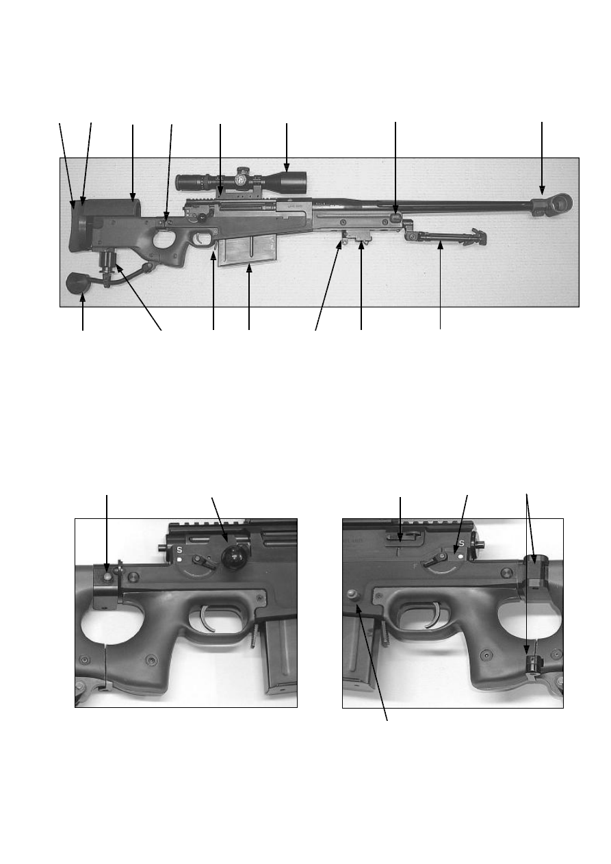
3.0 Top Level GA/Parts Identification
A Butt Pad
H
Magazine Release Catch
N
Bolt Release Catch
B Cheekpiece
I
Magazine
O
Safety Lever
C Scope Mount
J
Hand Stop/Bipod Mount
P
Folding Stock Hinges
D Telescope
K
Bipod
R
Folding Stock Retaining
E Muzzle Brake
SL Sling Loop Attachment Points
Spigot
F
Third Leg Support
L
Folding Stock Release Button
G Third Leg Adjustment
M
Bolt Handle
Fig. 01 General Arrangement/Parts Identification
A
B
I
G
F
E
D
C
SL
K
J
SL
SL
SL
P
H
O
N
M
L
R
AW50 Users Manual
8
4.0 Safety
4.1
General
4.1.1 This manual must be read and fully understood before attempting to use the
weapon system.
4.1.2 From time to time the manual uses cautionary notices to alert the user to either
safety imperative or potential instances which may result in causing damage to the
weapon system, as shown below: -
4.1.3
CAUTION
The safety precautions set out under section 4.4 “Safe Handling
Instructions”, must be strictly adhered to, when: -
•
On initial receipt of weapon
•
Before operating the rifle
•
After use before maintenance
•
Before any inspection
•
When the documentation recommends it
4.2
Safety Features
4.2.1 The AW50’s bolt utilises six forward locking lugs.
When in the closed position, the bolt head is completely enclosed and supported
within the lock ring and the action body.
4.2.2 The firing pin cannot protrude from the front of the bolt face unless the bolt is in the
fully closed position.
4.2.3 Gas leakage from the rear of the action is minimised by a tight fitting bolt. Should
there be an excessive build up of gas, it will be safety vented away through two
exhaust ports in the action and one in the bolt.
Note: -
In normal service the gas ports are fitted with red plastic caps to
prevent the ingress of debris/moisture. New caps should always
be fitted after gas has been exhausted through the ports.
4.2.4 The rifle is fitted with a two-stage trigger, which gives a fine let off. Accidental
discharge that might be caused by slamming the bolt or dropping the rifle is
reduced through increased first stage sear engagement.
Accuracy International Ltd.
9
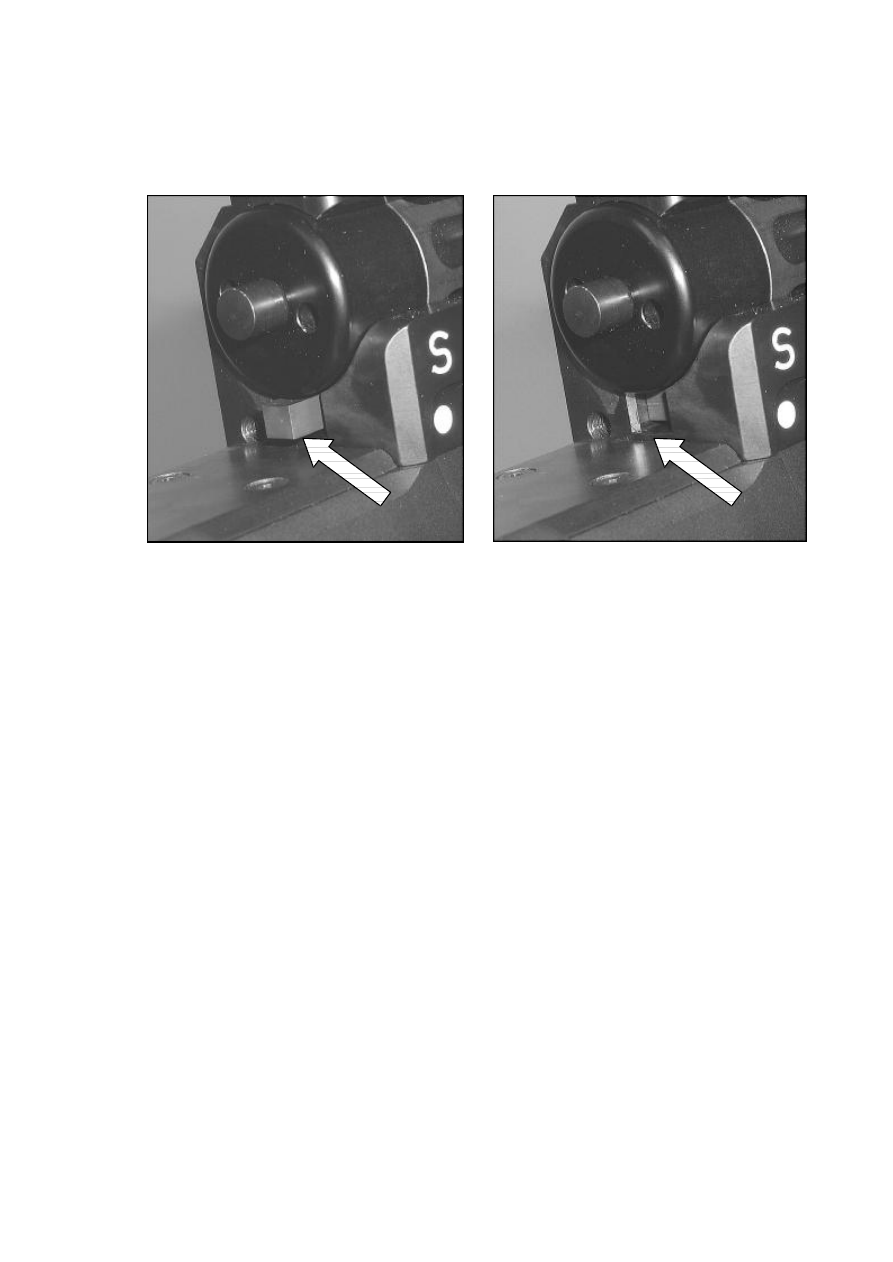
4.3
Firing Pin Cocking Indicator
4.3.1 The user can ascertain whether or not the rifle is cocked by the position of cocking
piece indicator protruding through the rear of the action.
Fig. 02 Cocking Piece Indicator - Cocked
Fig. 03 Cocking Piece Indicator - Fired
AW50 Users Manual
10
4.4
Safe Handling Instructions
4.4.1 It is forbidden without any reason to point the rifle at anybody.
4.4.2 When users are unaware of the weapon status (half loaded, loaded or unloaded), it
should always be assumed that it is LOADED.
4.4.3 A weapon which is to be handed over must be presented unloaded and with the
bolt open, in the rearwards position.
4.4.4
CAUTION
Before handling the rifle or attempting any operation, the user must
ensure theirs and the safety of others by: -
•
Standing behind the weapon
•
Ensuring it is pointing in a safe direction
•
Checking it is unloaded and safe to handle
4.4.5
CAUTION
NEVER fire the rifle before you have ensured rifle that: -
•
The muzzle brake is securely fitted and is not clogged or
obstructed
•
The serial numbers of the action body and the bolt assembly
match
4.4.6 Failure to fully close the bolt every time the bolt is manipulated could result in a live
round being left in the chamber, as the extractor does not engage the cartridge rim
unless the bolt is fully closed.
4.4.7
CAUTION
When operating the bolt ALWAYS cycle fully i.e. completely open and
close the bolt every time it is manipulated.
4.4.8 Tactical movements with a loaded weapon are only to be performed with the safety
lever set to the "SAFE position" (opposite the white dot).
Accuracy International Ltd.
11
4.5
Checking That The Rifle Is Unloaded
4.5.1 Remove the magazine from the rifle, see section 5.7 “Insertion & Removal Of The
Magazine” and ensure it is clear of ammunition.
4.5.2 Check that the safety lever is set on the "FIRE" position (opposite the red dot).
4.5.3 Raise the bolt handle and slide the bolt fully to the rear.
4.5.4 Check that the action is clear of ammunition by looking through the ejection port
and using a finger to feel inside the chamber.
4.5.5 The bolt should be left open or removed whilst handling rifle, see section 5.6
“Fitting & Removal Of The Bolt” for instruction on how to remove the bolt.
4.5.6 To close the bolt without causing unnecessary stress on the
firing pin and bolt
assembly, pull the trigger shoe and whilst holding it to the rear, fully close the bolt
before releasing the trigger.
4.5.7 Replace an empty magazine in the weapon.
4.5.8 The rifle may now be handled safely.
4.5.9
CAUTION
Before firing the rifle, always check the bore is free of obstructions.
4.6
Checking That The Bore Is Free Of Obstructions
4.6.1 Check that the rifle is unloaded, see section 4.5 “Checking That The Rifle Is
Unloaded”.
4.6.2 Fold the stock and remove the bolt, see section 5.2 “Unfolding & Folding The
Stock” and 5.6 “Fitting & Removal Of The Bolt” for relevant instruction.
4.6.3 Look through the barrel to ensure that it is free from obstructions and then replace
the bolt.

AW50 Users Manual
12
4.7
Safety Lever Operation
4.7.1 The AW50 has two modes of operation: -
•
Safe
•
Fire
4.7.2
CAUTION
There is only one position where the rifle is safe.
This is when the lever is EXACTLY opposite the white dot under the
“S”.
No other position is safe.
4.7.3 The safety lever can only be applied after the rifle has been cocked.
4.7.4 With the safety lever applied: -
•
The firing pin is withdrawn and is physically blocked from coming forward.
•
The trigger is physically blocked.
•
The bolt is locked in the closed position.
4.8
Checking The Firing Pin’s Safe Operation
4.8.1 Open and close the bolt to leave it in the cocked position.
4.8.2 Move the safety lever into the “SAFE” position.
4.8.3 Pull and release the trigger 6 times and remove your finger from the trigger.
4.8.4 Push the safety lever forward into the "FIRE” position.
4.8.5 If the rifle is operating correctly the firing pin should not be released; it will still be
retained by the trigger mechanism.
4.8.6 Pull the trigger to release the firing pin.
4.8.7 If moving the safety lever to the “FIRE” position releases the firing pin; then the rifle
is deemed to be unsafe and must be returned to the Base Armourer for
maintenance.

Accuracy International Ltd.
13
5.0 Operating Instructions – Rifle
5.1
Assembling The Rifle
5.1.1 Rifles are normally supplied as complete units within their transit cases (with the
scope, bolt, bipod and magazine already fitted to the rifle).
Note: -
Rifles will be folded during transit.
5.1.2 However, if the rifles are broken down for transport they will need to be assembled
in sequence, using the instructions below.
5.2
Unfolding & Folding The Stock
5.2.1 To unfold the stock, support the rifle within one arm and taking hold the butt with
the other hand give a quick/sharp pull to release the retaining spigot from the
female bush.
5.2.2 Continue to pull the stock round until it ‘snaps’ back into the locked position.
5.2.3 To fold the stock press the release button, located on the right hand side of the
chassis, just behind the action body.
5.2.4 Push the rear end of the stock round to the left hand side of the rifle until it’s female
bush engages on the male retaining spigot.
5.2.5 The stock is now held in the folded position.
AW50 Users Manual
14
5.3
Fitting & Removal Of The Bipod
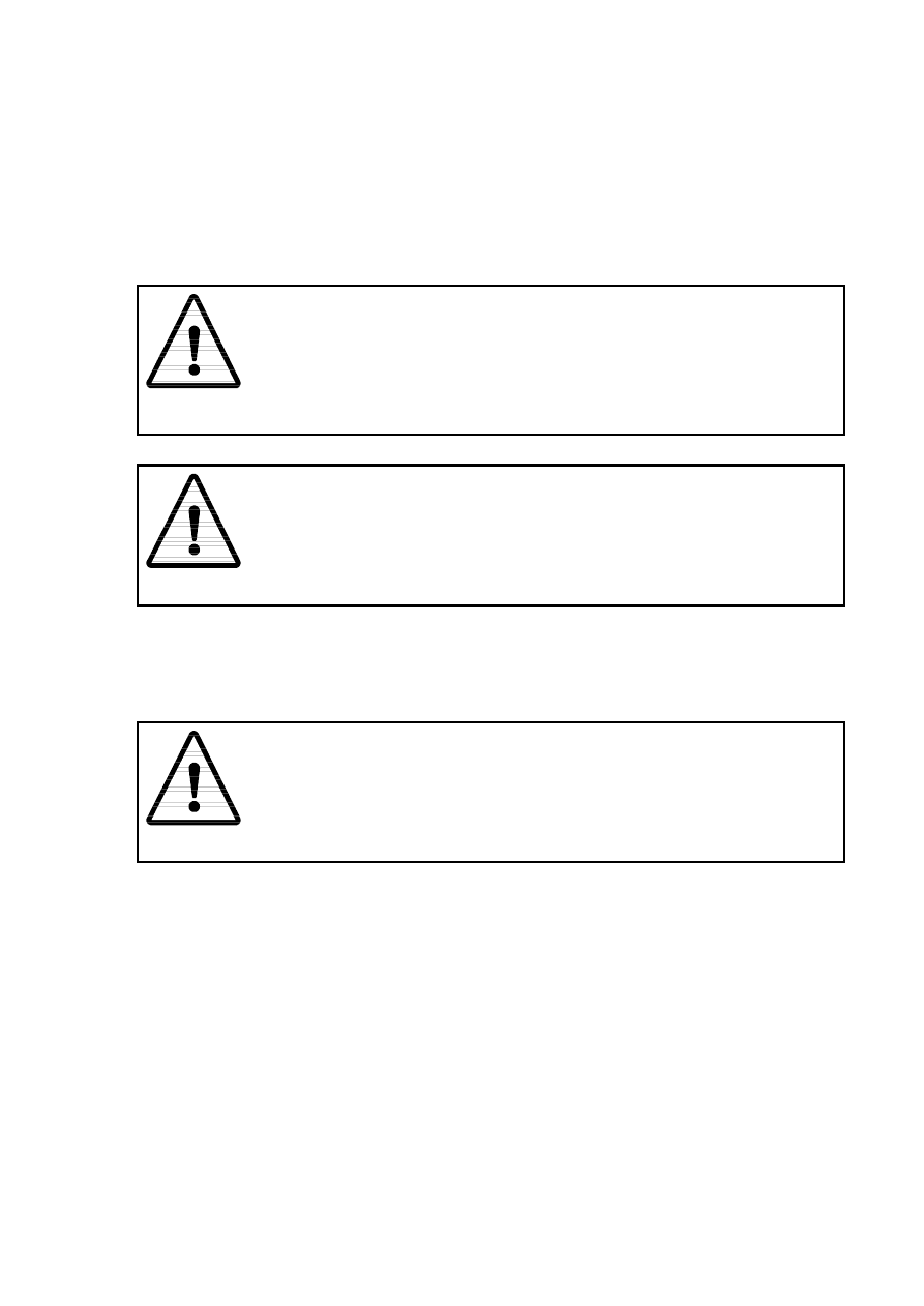
Fig. 04 Bipod
5.3.1 To fit the bipod, insert its spigot into the socket at the front of the rifle forend (or the
hand stop/bipod mount, where fitted) until the catch engages.
5.3.2 Correct engagement can be assured on hearing an audible ‘click’ when the bipod is
pushed home.
5.3.3 Alternatively, when operational the user can reduce the noise made inserting the
bipod by holding the bipod release catch open whilst the bipod is pushed home.
5.3.4 To remove the bipod, depress the bipod release catch and pull the bipod out of the
socket.
Fig. 05 Fitting & Removal Of The Bipod
Spigot
Release Catch
Accuracy International Ltd.
15
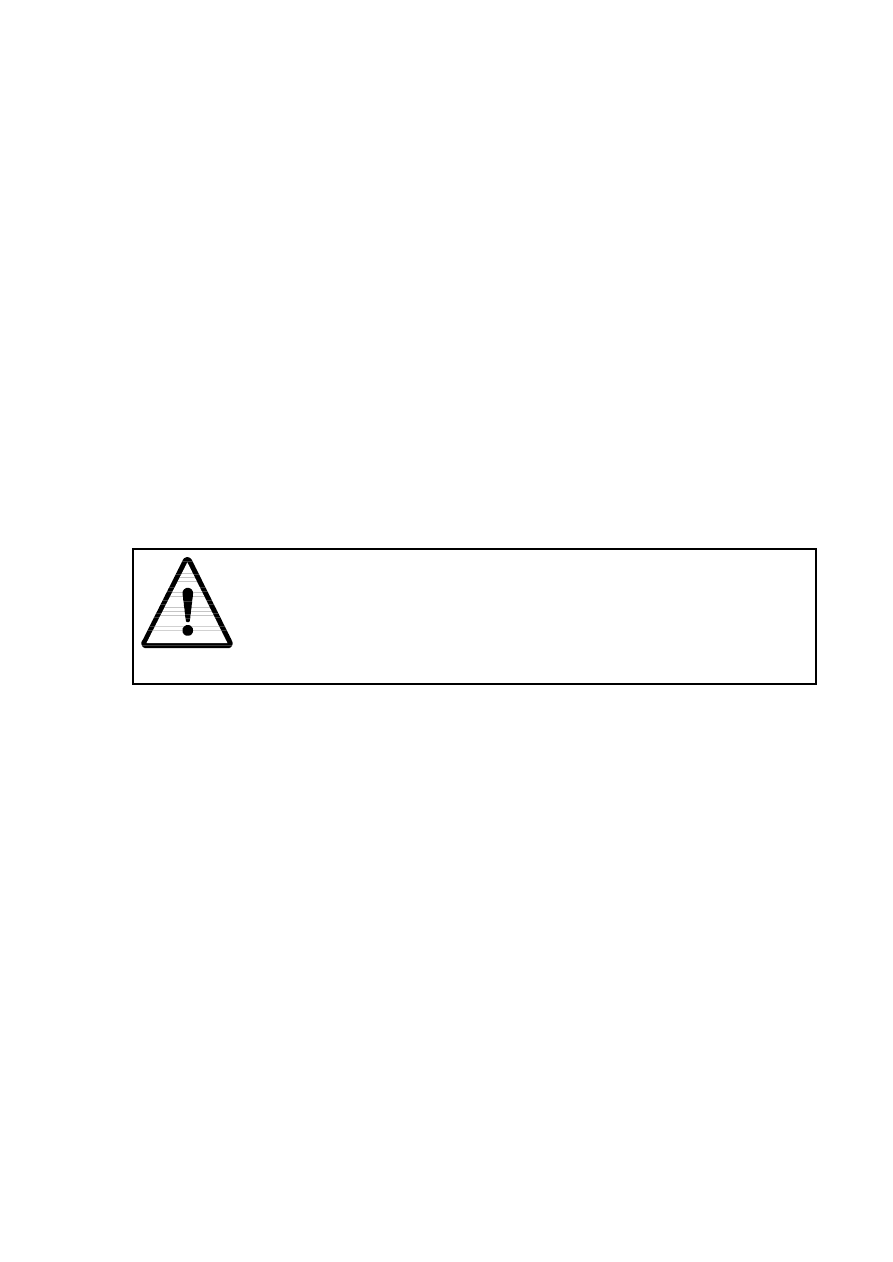
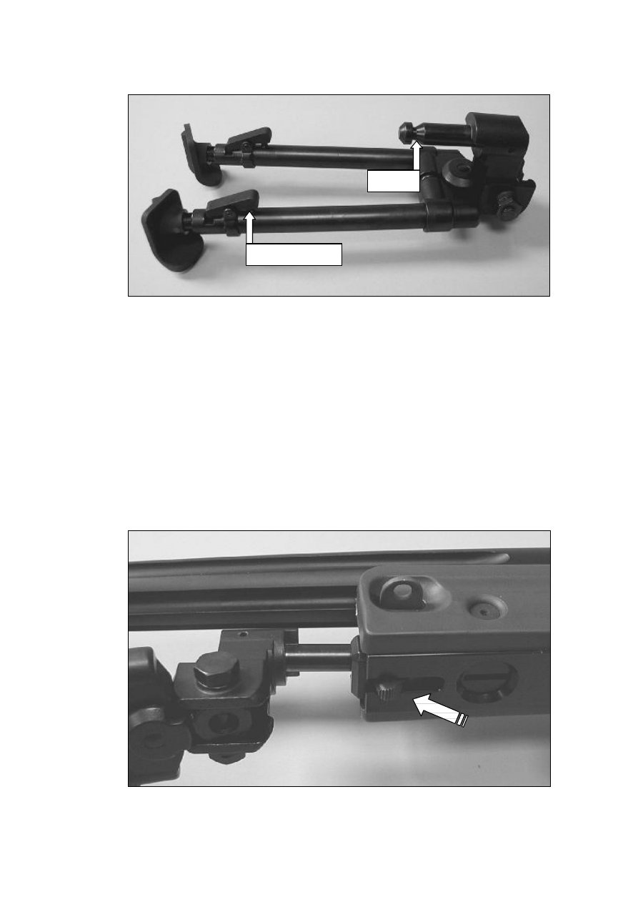
5.4
Fitting & Removal Of The Hand Stop/Bipod Mount
5.4.1 The adjustable hand stop/bipod mount allows the user to adjust the bipod’s position
along the length of the forend.
5.4.2 To fit the adjustable hand stop/bipod mount, use the universal Allen key set to
loosen the screw/nut until there is sufficient clearance for the mount to be fitted, but
do not undo it completely.
5.4.3 Where the rifle cannot be turned over, use the Allen key to push against the screw
to maintain the clearance whilst inserting the hand stop/bipod mount into the
circular opening at the end of the keyway.
5.4.4 Slide the hand stop/bipod mount along the keyway and tighten the screw/nut when
it is in the desired position.
5.4.5 To remove the hand stop/bipod mount, loosen the screw/nut and remove it through
the circular opening at the end of the keyway.
Fig. 06 Fitting & Removal Of The Hand Stop/Bipod Mount
AW50 Users Manual
16
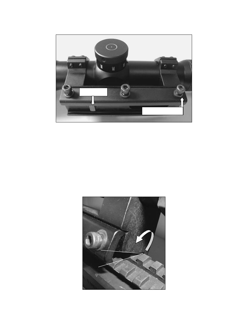
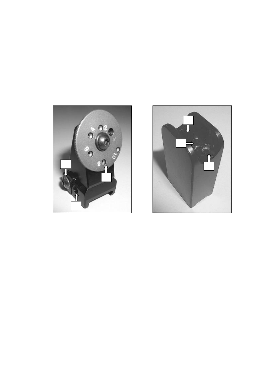
5.5
Fitting & Removal Of The Scope/Mount
Fig. 07 Scope Mount
5.5.1 To fit the scope/mount, use the universal Allen key set to loosen the three mount
screws (if they have been done up) until there is sufficient clearance for the mount
to be fitted.
5.5.2 Present the mount to the Picatinny rail at an angle of approximately 30 degrees and
align the recoil lug with the appropriate slot.
5.5.3 Hook the mount’s fixed dovetail (on the opposite side to the securing screws) onto
the rail’s mating face before rolling the mount over to the upright position.
Fig. 08 Fitting The Scope Mount Onto The Rail
Securing Screws
Recoil Lug
Accuracy International Ltd.
17
5.5.4 Before re-tightening the mount securing screws ensure that the mount’s recoil lugs
are pushed forward against the slot in the rail.
5.5.5 It is recommended that a routine be established for retightening the screws to
ensure that the scope/mount is fitted consistently each time.
5.5.6 Typically after the bolts have been made finger tight, the front and rear screws
should be tighten alternately by ¼ of a turn at a time, until they are tight.
The centre screw can then be tightened to the same extent.
5.5.7 To remove the scope/mount, loosen the clamp plate’s three screws until there is
sufficient clearance for the mount to be lifted off.
5.5.8
CAUTION
It is recommended that the scope is re-zeroed following any changes
to its position.
Unnecessary removal/refitting of the scope from the picatinny rail or
within the mount’s scope rings should therefore be avoided.
AW50 Users Manual
18
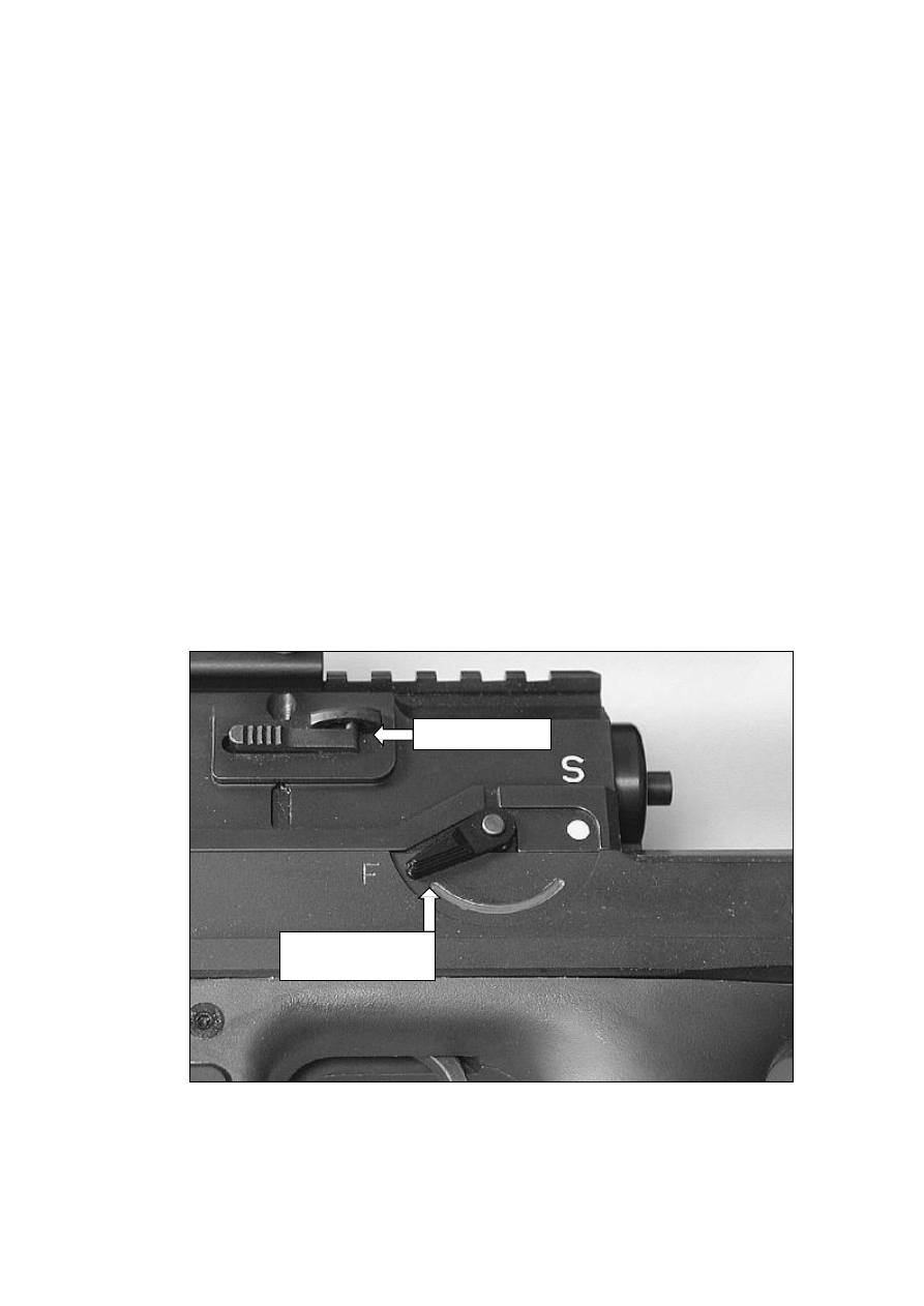
5.6
Fitting & Removal Of The Bolt
5.6.1 The bolt can only be fitted/removed from the rifle when the stock is folded position
and the safety lever is in the “Fire” position.
5.6.2 To fit the bolt, ensure that the safety lever is set in the “Fire” position.
5.6.3 Check that the serial numbers of the bolt and the action are the same. If they are
different do not fit the bolt and contact the Base Armourer.
5.6.4 Fold the stock back to allow sufficient clearance for the bolt to be replaced. Its
recommended that it be folded fully back onto itself and locked in this position see
section 5.2 “Unfolding & Folding The Stock”.
5.6.5 Fit the bolt into the bolt way and whilst depressing the bolt release catch, slide the
bolt fully forwards.
5.6.6 Release the bolt catch, pull the trigger shoe and whilst holding it to the rear, close
the bolt before releasing the trigger shoe.
5.6.7 To remove the bolt, hold the bolt handle in the right hand. Raise the handle and
slide the bolt rearwards until it stops on the bolt catch.
5.6.8 Using the left hand, depress the bolt release catch and fully withdraw the bolt from
the action.
Fig. 09 Fitting & Removal Of The Bolt
Release Catch
Safety Lever In
The Fire Position
Accuracy International Ltd.
19
5.7
Insertion & Removal Of The Magazine
5.7.1 The box magazine is inserted by locating it into the opening in the underside of the
rifle.
5.7.2 Hold the magazine by its base using the left hand and push it upwards until the
catch engages.
5.7.3 Correct engagement can be assured on hearing an audible ‘click’ when the
magazine is pushed home.
5.7.4 Alternatively, when operational the user can reduce the noise made inserting the
magazine by holding the magazine release catch open whilst the magazine is
pushed home.
5.7.5
CAUTION
Always check that the magazine has been correctly engaged and is
secure, by pulling down on the base plate.
5.7.6 To remove the magazine, push the magazine release catch forward with the thumb
of the right hand, whilst holding the left hand underneath the magazine to support it
as it comes away from the rifle.
AW50 Users Manual
20
5.8
Setting Up The Rifle
5.9
Holding The Rifle
5.9.1 In its standard form, the rifle has been designed for shooting from the prone
position, utilising the bipod and the third leg to support and help absorb recoil.
Note: -
Use of a suitable mounting capable of absorbing the recoil is
recommended when the rifle is to be shot in any other position.
5.9.2 Having adopted the prone position, hold the pistol grip with the right hand and pull
the rifle firmly into the shoulder.
5.9.3 Rest the cheek on the butt’s cheekpiece so that the eye is looking directly through
the sight.
5.9.4 If necessary adjust position of the telescopic sight to obtain correct eye relief see
section
8.4 “Eye Relief Adjustment”.
5.9.5 Position the left hand so that it grips the fine adjustment knob on the underside of
the butt.
5.9.6 This provides additional support but it also permits fine adjustments to be made to
the height of third leg whilst remaining the firing position.
Fig. 10 Setting Up The Rifle
5.9.7 The bipod and the third leg should be adjusted to align the rifle with the target in
various terrains and allow the user to comfortably maintain the hold over an
extended period of time.
Accuracy International Ltd.
21
5.10
Bipod Adjustment
5.10.1 The bipod’s legs can be extended together or independently to compensate for
variations in the ground level.
5.10.2 A castellation along the leg’s length allows the spring-loaded leg to be extendable
and to be locked into a secure position.
5.10.3 To adjust the bipod’s height, depress the bipod leg catch release the leg to extend
to the castellation appropriate to the desired height.
5.10.4
CAUTION
Always ensure that the bipod leg catch is securely engaged in
the castellation.
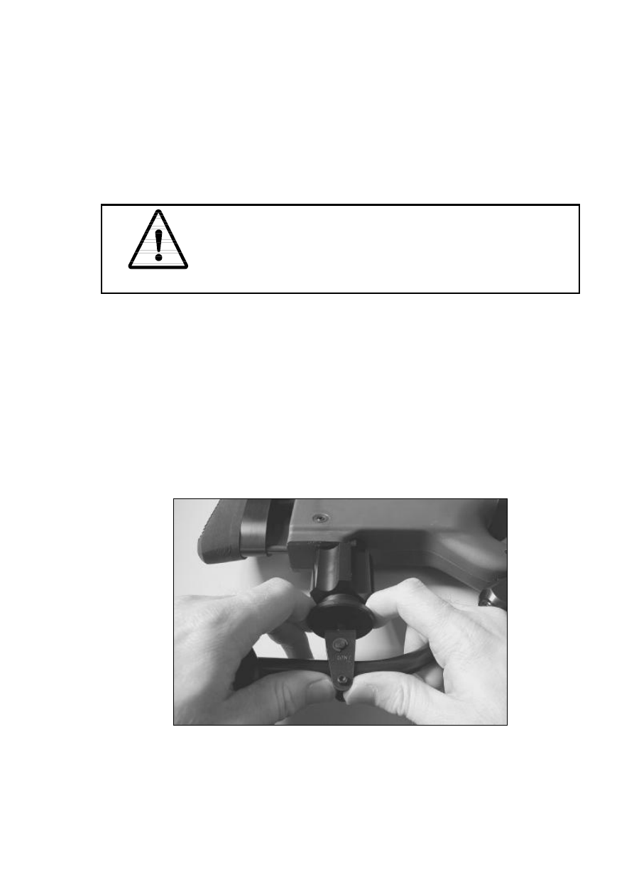
5.11
Third Leg Adjustment
5.11.1 The third leg can be coarsely adjusted via spring loaded quick release mechanism
and finally adjusted with the fine adjustment knob to obtain an exact height.
5.11.2 A castellation along the inner sleeve’s length allows the spring-loaded leg to be
extendable via quick release mechanism and to be locked into a secure position.
5.11.3 To operate the quick release mechanism, take the weight off the third leg and
place two fingers either side of the disc below the fine adjustment knob.
5.11.4 Pull down on the disc to release the leg to extend to the castellation appropriate to
the desired height.
Fig. 11 Third Leg Adjustment
5.11.5 The height can be finely adjusted within the prone position by using the left hand
to rotate the fine adjustment knob.
•
If the butt is too low, rotate the knob clockwise to raise.
•
If the butt is too high, rotate the knob anti-clockwise to lower.
AW50 Users Manual
22
5.12
Preparing To Fire The Rifle
5.12.1
CAUTION
Ensure that the rifle has been correctly cleaned and lubricated
before use, see section 6.2 “Cleaning & Lubricating Before Firing”
and 6.3 “Cleaning The Barrel & Chamber Before Firing”.
Whenever loading, reloading or unloading ensure that the fingers are
kept outside of the trigger guard.
5.13
Loading
5.13.1 To load the rifle, place a full magazine into the magazine well.
5.13.2 Push the magazine upwards until the magazine retaining catch engages on the
magazine’s lug.
5.13.3 If the bolt is in the closed position, open the bolt by fully raising the bolt lever and
pulling it backwards until it reaches its stop.
5.13.4 To feed a round from the magazine into the chamber, push the bolt lever fully
forward and then down into the closed position.
5.13.5
CAUTION
The rifle is now cocked and is able to be fired. The safety lever
should be applied as necessary.
5.13.6
CAUTION
The extractor does not engage the cartridge rim unless the bolt is
fully closed.
Failure to fully close the bolt every time that it is manipulated could
result in a live round being left in the chamber.
5.13.7 Note: -
If It is difficult to get the magazine to engage with the bolt closed or
the first round is difficult to feed into the chamber check the that the
magazine has not been over loaded.

Accuracy International Ltd.
23
5.14
Firing & Operating The Bolt
5.14.1
The sequence detailed below assumes that the user has already identified the
target and made the relevant adjustments to optimise the scope or iron sight.
5.14.2
Set the range and windage on whichever sighting system is to be employed.
5.14.3
Move the safety lever to the “Fire” position.
5.14.4
Push the rifle firmly into the bipod with the shoulder (to pull back on the bipod
can cause vertical stringing of shots, especially on soft ground).
5.14.5
Place the finger naturally on the trigger without pulling it.
5.14.6
Whilst taking a few deep breaths take up the first pressure.
5.14.7
Breathe out normally and perfect the aim, whilst applying a gradual increase of
trigger pressure to fire.
Note: -
Exhaling reduces pulse beat whilst in the prone position on the
ground
5.14.8
Maintain trigger pressure and concentration on the aim until the weapon recovers
from the recoil (follow through).
5.14.9
Release the trigger, resume normal breathing and observe the target.
5.14.10 To minimise the movement of the rifle and body (right handed users only) remain
in the aim position during recycling.
5.14.11 Place a thumb on the top of the action and grasp the bolt handle with the fingers
of the right hand.
5.14.12 Bring the fingers up towards the thumb. If any resistance is felt during the initial
unseating of the fired case (primary extraction), increase the upward pressure on
the bolt handle.
5.14.13 Pull the bolt to its most rearward position i.e. to touch the bolt stop, to allow the
fired case to be ejected and to pick up the next round.
5.14.14 Push the bolt forward to feed the next round into the chamber and close the bolt.
5.14.15 Repeat this sequence of operation if further shots are necessary.

AW50 Users Manual
24
5.15
Reloading
5.15.1 Remove the expended magazine and insert a fresh one as previously described,
see section 5.7 “Insertion & Removal Of The Magazine”
5.15.2 Close the bolt (open it fully where was previously left in the closed position) to
feed a new round into the chamber.
5.15.3 Move the safety lever to the “Safe” position.
5.15.4 The rifle is now loaded, cocked and ready to engage a new target.
5.16
Unloading
5.16.1 Remove the magazine from the rifle.
5.16.2 Open the bolt and pull it to its most rearward position i.e. to touch the bolt stop, to
allow the fired case to be ejected.
5.16.3 Check that the rifle is clear of ammunition by looking through the ejection port and
using a finger to feel inside the chamber.
5.16.4 The bolt should be left open, unless the rifle is to be put into its transit case, in
which case: -
5.16.5 Pull the trigger shoe and whilst holding it backwards, close the bolt before
releasing the trigger.
5.16.6 Replace an empty magazine in the weapon.
5.17
Unloading A Live Cartridge
5.17.1 Set the safety lever as necessary to the “Fire” position.
5.17.2 Remove the magazine from the rifle
5.17.3 Cup the right hand and position it just to the side and below the ejection port to
catch the round as it is ejected.
5.17.4 Using the left hand reach over the rifle and cycle the bolt to unload the chamber.
5.17.5 Note: -
The user may maintain a lower profile by reversing the right and left
hands within the procedure above.
However it means that it is necessary to reach under the rifle
restricting the ease of movement and attempt to catch the round with
a potentially weaker hand.
Accuracy International Ltd.
25
5.17.6 Check that rifle is clear of ammunition by looking through the ejection port and
using a finger to feel inside the chamber.
5.17.7 The bolt should be left open, unless the rifle is to be put into its transit case, in
which case: -
5.17.8 Pull the trigger shoe and whilst holding it to the rear, close the bolt before
releasing the trigger.
5.17.9
CAUTION
All live rounds MUST be removed from the magazines (either in the
rifle or separate) prior to being stored in the transit case.

AW50 Users Manual
26
5.18
Zeroing The Rifle To A Telescopic Sight
5.18.1
CAUTION
Refer to Safe Handling Instructions; see section 4.4 “Safe Handling
Instructions”.
5.18.2
Choose a suitably short range to reduce the wind effects to a minimum, typically
100 metres.
5.18.3
Check that the sight’s windage is set to zero and elevation drum is set to a mid
range position i.e. 9 on the top scale.
5.18.4
Check that the zoom is set to its highest magnification and focus the reticule.
5.18.5
Open the bolt, insert a loaded magazine and close the bolt.
5.18.6
Whilst looking through the telescope, align reticule’s aiming point on the target’s
aiming mark.
5.18.7
Fire one shot.
5.18.8
Sandbag or hold the rifle carefully so it cannot move from its original point of aim.
5.18.9
Taking care not to move the rifle, gently rotate the windage drum until reticule is
in vertical line with the shot hole.
•
If the shot is too much to the left, rotate the windage drum clockwise.
•
If the shot is too much to the right, rotate it anti-clockwise.
5.18.10 Still taking care not to move the rifle, rotate the elevation drum until the reticule’s
aiming point is over the bullet hole.
•
If the shot is too low, rotate the elevation drum clockwise.
•
If the shot is too high, rotate the elevation drum anti-clockwise.
5.18.11 Note: -
Where there is insufficient movement to allow the drums to be
adjusted, loosen the two grub screws securing the drum.
Rotate the drum to allow additional movement in the direction
required, before retightening the grub screws.
5.18.12 Fire a second shot at the original aiming mark (or 2 to 3 to form a group).
5.18.13 ‘Click’ the windage and elevation drums to finely adjust the reticule’s aiming mark
over the point of impact.
5.18.14 Fire a five shot group and make any final adjustments. Repeat group if required
for confirmation.

Accuracy International Ltd.
27
5.18.15 On completion of zeroing, record of the position of elevation and windage drums.
5.18.16 Whilst holding the drums firmly between the fingers so as not to lose the setting,
loosen the grub screws (2 ea. per drum) using the universal Allen key set.
5.18.17 Rotate the drums to zero and re-tighten the grub screws.
5.18.18 The rifle is now zeroed.
5.18.19 By using the elevation markings on the sight-drum and a graph, the true settings
at various ranges can be established and marked on the graph when shooting
with the same ammunition type as used when the rifle was zeroed.
A graph will enable the sniper to establish the correct elevation setting at all
usable ranges.
AW50 Users Manual
28
5.19 Iron Sights
5.19.1 A disc type iron sight set is provided with the AW50 for use in the event of a failure
with telescopic sight.
5.19.2 The sight has settings for ranges of 200, 400, 600, 800 and 1000 metres.
A larger aperture for use in low light conditions is provided at number 4, 400
metres position.
5.19.3 For zeroing purposes, the rear sight is adjustable for windage and Foresight
adjustable for elevation.
Fig. 12 Iron Sights – Rear Sight
Fig. 13 Iron Sights – Fore Sight
A
Mount Securing Screw
D
Mount Securing Screw
B
Windage Adjustment Screws
E
Post
C
Range Elevation Disc
F
Vertical Adjustment
5.20
Fitting & Removing The Iron Sights
5.20.1 To fit the rear sight, use the universal Allen key set to loosen the screw in the
mount’s base until there is sufficient clearance for it to be fitted to the rail.
Note: -
The mount does not have a recoil lug so it can be slid along the rail
to whatever position the user finds comfortable when in the prone
position.
5.20.2 Tighten the mount’s screw.
5.20.3 To fit the foresight, locate the sight’s keyway over the muzzle brake’s mating face
(with the post foremost) so that the securing screw can be tightened using the
universal Allen key set.
5.20.4 Loosen the screws to remove the sights.
E
F
C
B
A
D

Accuracy International Ltd.
29
5.21
Zeroing The Rifle To The Iron Sights
5.21.1
CAUTION
Refer to Safe Handling Instructions; see section 4.4 “Safe Handling
Instructions”.
5.21.2
Set up a large target at 200 metres.
5.21.3
Rotate the rear sight’s disc to the number 2 position and ensure that the body of
the sight is centrally located on its base (see below for instruction on how to
adjust).
5.21.4
Open the bolt, insert a loaded magazine and close the bolt.
5.21.5
Look through the disc’s number 2 hole and with the target’s aiming mark
centrally aligned within the aperture; position the top of the post so that it is
central and aligns with the base of the aiming mark.
5.21.6
Fire three shots and note the Mean Point Of Impact (MPI) on the target.
5.21.7
For horizontal adjustments to the MPI, use the universal Allen key set to loosen
the windage screws on either side of the sight’s main body.
•
If MPI is too much to the left, move the sight to the right by undoing the right
hand side screw and tightening the left, by equal amounts.
•
If MPI is too much to the right, move the sight to the left by undoing the left
hand side screw and tightening the right, by equal amounts.
Note: -
If the error is too great and cannot be adjusted by the rear sight’s
windage screws, coarse adjustment may be obtained by loosening
the muzzle brake’s two clamp screws. However, the direction of
adjustment is reversed.
5.21.8
Vertical adjustments are carried out by moving the post’s height within the
foresight
•
If the MPI is too low, turn the screw clockwise to lower the post
•
If the MPI is too high, turn the screw anti-clockwise to raise the post
5.21.9
Repeat the process above as required until a satisfactory zero is achieved.
5.21.10 Upon completion, note where the rear sight is fitted on the rail as any deviation
may affect the zero.
5.21.11 The rifle is now zeroed at 200m, range elevations are achieved by rotating the
disc to the required range.
AW50 Users Manual
30
5.22 Disassembling The Rifle
5.22.1 The user should not disassemble the rifle further than that previously described
within section 5.1 “Assembling The Rifle”.
5.22.2 Unlike other AW rifles, the AW50’s bolt assembly is non-user maintainable.
5.22.3 Under no circumstances should the user conduct any more maintenance other
than routine cleaning and lubrication of its external surfaces.
5.22.4 A qualified armourer should carry out all further maintenance. If doubt the user
should seek the armourers advice.
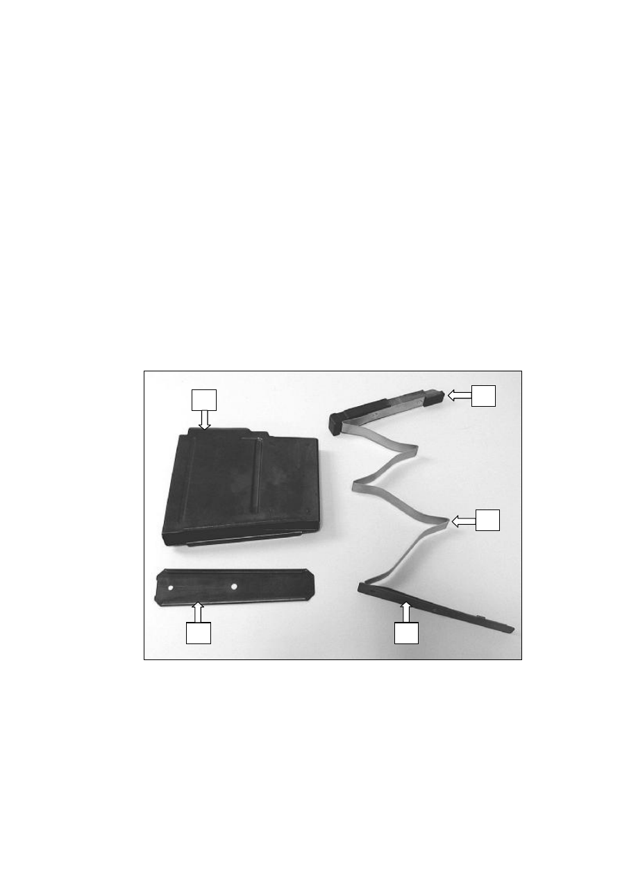
5.23
Stripping The Magazine
5.23.1 Magazines should be stripped if and when they have been exposed to conditions
likely to result in a build up of mud, grit or rust.
Care should be taken not the damage the magazine platform or to bend the round
securing ears from their original form.
Fig. 14 Stripped Magazine Assembly
A Magazine Body
D Magazine Spring
B Magazine Base
E Magazine Base Locking Plate
C Magazine Platform
A
B
D
C
E
Accuracy International Ltd.
31
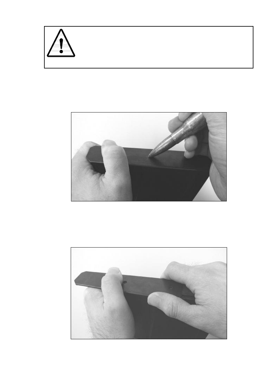
5.23.2
CAUTION
The magazine platform is under tension.
Keep a hand over the opening when removing the bottom plate, to
prevent the spring from ‘jumping out’.
5.23.3 To strip the magazine, hold it in the left hand with the bottom plate uppermost.
5.23.4 With the nose of a round, depress the stud located in the bottom plate and slide
the bottom plate forwards, part way open.
Fig. 15 Stripping The Magazine – Removing The Base Plate Stage 1
5.23.5 Remove the bullet and whilst holding the right hand over the bottom of the
magazine, slide the bottom plate completely off.
Fig. 16 Stripping The Magazine – Removing The Base Plate Stage 2
AW50 Users Manual
32
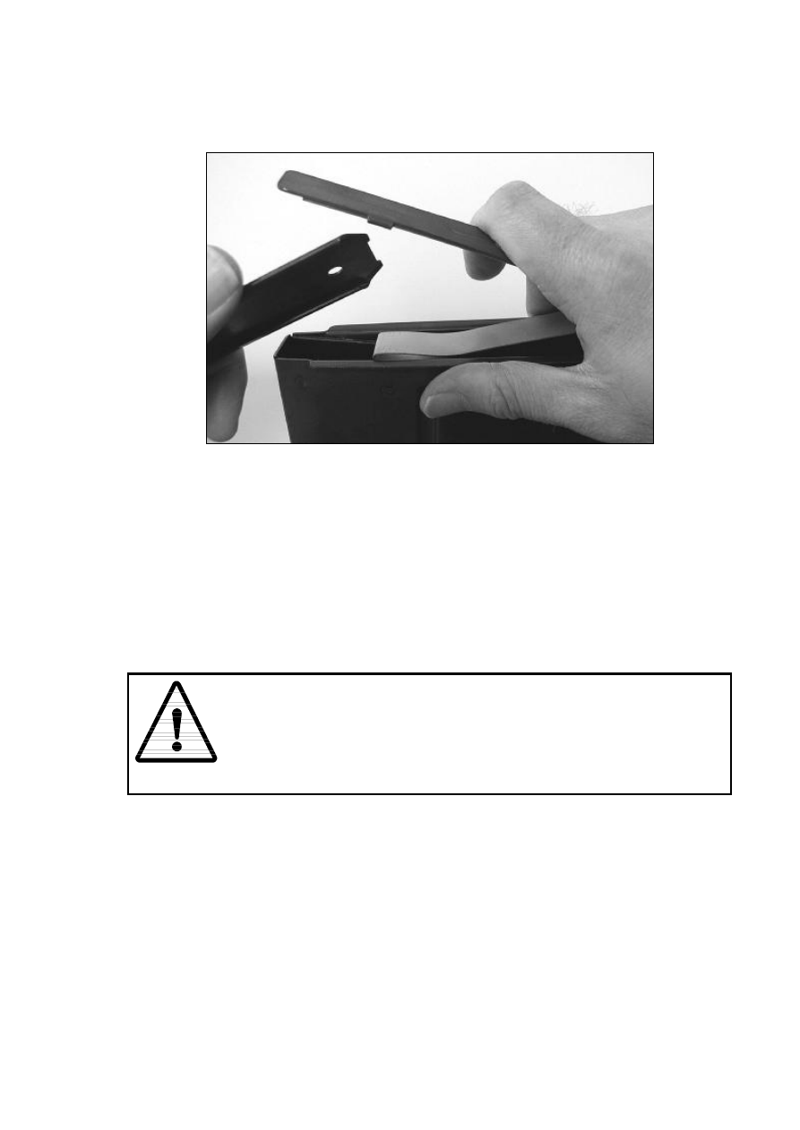
5.23.6 The spring is now released; slowly lift the right hand away, taking hold of the
spring as it uncoils from the magazine.
Fig. 17 Stripping The Magazine – Removing The Spring Assembly
5.23.7 Carefully feed the spring out of the magazine so not to damage the attached
platform.
5.23.8 Reassembly is conducted in reverse order to stripping, ensuring that the
magazine platform and spring base are correctly aligned with the magazine’s
profile.
5.24
Tests After Re-assembly
5.24.1
CAUTION
Specially prepared “dummy” rounds should be used to conduct this
test.
5.24.2 Load the magazine with inert test rounds, to its fullest capacity.
5.24.3 Whilst loading check to ensure that the lips of the magazine hold each round in
position.
5.24.4 Load the magazine into a functional rifle.
5.24.5 Operate the bolt and check that each round is fed in, extracted and ejected
correctly.

Accuracy International Ltd.
33
6.0 User Maintenance – Rifle
6.1
General
6.1.1 This section only covers the level of maintenance that the user would be expected
to perform using the tools supplied with the rifle.
It recognises that a user is unlikely to be able to conduct the same level of
maintenance whilst operational.
Complete maintenance procedures are defined in the Maintenance Manual
6.1.2 To ensure the rifle is not damaged whilst being cleaned and lubricated only the
recommended tools, cleaning materials and lubricates should be used in
accordance with these instructions.
6.1.3 No abrasive material should be used on any part of the rifle. If cleanliness cannot
be achieved using the methods and materials described below the fault should be
reported to the Base Armourer.
6.1.4 If while cleaning and lubricating the rifle the user identifies any faults or damage, it
should be reported to the Base Armourer.
6.2
Cleaning & Lubricating Before Firing
6.2.1 Before firing the rifle it must be cleaned and lubricated as detailed below: -
Part
Lubrication Status
Bore, chamber & barrel - Exterior
N/A - Leave dry
Bore, chamber & barrel - Interior
Clean and leave dry, see section 6.3
“Cleaning The Barrel & Chamber Before
Firing”.
Bolt – Front face
Clean and leave dry
Bolt - Remaining surfaces
Lightly lubricate with CLP 16 oil
Action body
Lightly lubricate the inside surfaces with CLP
16 oil
Stock & outer bipod legs
N/A - Leave dry
Bipod inner legs
Lightly lubricate with CLP 16 oil
Bipod upper body
Lightly lubricate with a smear grease
AW50 Users Manual
34
6.3
Cleaning The Barrel & Chamber Before Firing
6.3.1
CAUTION
Before cleaning the rifle ensure that lenses of the telescopic sight
are covered.
6.3.2
The use of a pull through is not recommended. The preferred option is to use a
cleaning rod.
6.3.3
Care must still be exercised when using the cleaning rod to avoid causing damage
to the bore and chamber.
6.3.4
The potential for chamber wear can be greatly reduced by using a rod guide to
ensure that the cleaning rod is held in the in the centre of the bore
6.3.5
Lock the stock in the folded position, see section 5.2 “Unfolding & Folding The
Stock”.
6.3.6
Securely hold the rifle on a level plane by a suitable means, ideally between the
protected jaws of a bench vice, where available.
6.3.7
Depress the bolt release catch and remove the bolt, see section 5.6 “Fitting &
Removal Of The Bolt”.
6.3.8
CAUTION
To avoid damaging the muzzle, the cleaning rod must always be
inserted from the breech end.
6.3.9
Gently push the rod guide through the action and into chamber until a click is
heard, signifying that the bolt catch has engaged.
6.3.10 Ensure the rod is clean before affixing a clean patch (10 cm x 5 cm) via a jag or
the patch holder.
6.3.11
CAUTION
When cleaning the bore with patches, always work in one direction,
breach to muzzle.
DO NOT pull used patches back through the bore.
6.3.12 Moisten a patch with Bore Solvent and push it once through the bore (via the rod
guide) and of the muzzle to wet the bore.
6.3.13 Remove the soiled patch from the cleaning rod. DO NOT attempt to pull the patch
back through the bore.

Accuracy International Ltd.
35
6.3.14 Remove the jag or the patch holder from the cleaning rod and refit with a correct
sized phosphor bronze brush.
6.3.15 Whilst the bore is still wet, wet the brush with solvent and pass it completely
through the bore in each direction several times.
Repeat with fresh solvent if necessary.
6.3.16
CAUTION
Always wet the bore with a patch before using a brush.
6.3.17 Refit the jag or patch holder to the cleaning rod and pass through a clean patch to
dry the bore and chamber.
Remove the patch at the muzzle DO NOT pull it back through the bore.
Repeat this operation if necessary, until the patches come out clean (a light grey
smudge is acceptable).
6.3.18 Where the rifle is to be stored for a lengthy period or when in a corrosion
atmosphere a thin smear of oil should be left in the bore.
6.3.19 Moisten a patch with CLP 16 oil and pass it once through the bore.
AW50 Users Manual
36
6.4
Cleaning & Lubricating After Firing
6.4.1 It is recommended that the barrel be cleaned after each shooting.
6.4.2 The bore and chamber are easier to clean immediately after shooting, whilst the
barrel is still warm.
6.4.3 Where this is not possible, the bore and chamber should be thoroughly oiled with
CLP 16 oil or similar to assist later cleaning.
6.5
To Clean Heavy Copper Fouling
6.5.1 Heavy copper fouling may be seen from the muzzle as a copper coloured residue
between the lands, although the heaviest fouling will occur towards the chamber.
Note: -
This operation may not be required for every cleaning.
6.5.2 Clean the bore and chamber as above, see section 6.4 “Cleaning & Lubrication
After Firing”.
6.5.3 Remove the jag or the patch holder from the cleaning rod and refit with a correct
sized phosphor bronze brush.
6.5.4 Allow the solvent to penetrate for approximately 5 minutes.
6.5.5 Refit the jag or patch holder to the cleaning rod and pass through a clean patch to
dry the bore and chamber.
Remove the patch at the muzzle DO NOT pull it back through the bore.
Heavy fouling will show as blue on the patch. Repeat this operation as necessary
until the patches come out clean.
6.5.6
CAUTION
Solvents must be used sparingly; any excess spillage outside of the
barrel must be removed immediately.

Accuracy International Ltd.
37
7.0 Recommended Lubricates & Cleaning
Solutions
Lubricant / Cleaner
Part Number
Typical Uses
CLP16 oil
AI15-0968
General cleaning and lubrication of
action and rifle exterior.
Penetrating oil ZX-54 8030-99-923-1633 Lubrication of the trigger.
Grease XG 279
8030-99-220-2418 Parts inside the shroud. Scope
mount.
Breakfree Bore
Cleaner
BC4
Bore solvent
AW50 Users Manual
38
8.0 Operating Instructions – Telescope
8.1
General Description – Telescope
8.1.1 Accuracy International recommends the Schmidt und Bender 3-12x50 MKII 0.2 milli
radian (MRAD) telescopic sight for use with the AW50.
8.1.2 The telescopic sight is composed of three drums, allowing adjustments for elevation,
windage and parallax.
Full movement of the elevation and windage drums can be carried out in one
complete turn. A click on either scale moves the sight reticule by 0.2 MRAD.
Stops are fitted at the beginning and at the end of the turn to aid the user to count of
the elevation and windage clicks to when shooting at night.
The zoom can be adjusted in order to allow the sniper to magnify the target between
three and twelve times
The eyepiece can be adjusted to accommodate dioptre deviation from +2 to -2
dioptres.
The design of the telescopic sight lenses allows more than 85 % light transmission.
The telescopic sight is fitted with a laser protection filter.
All metal components have a hard anodised finish, which is easily cared for and
offers a high resistance to scratches.
8.1.3 If ordered, the scope will be normally supplied fitted to the rifle having already been
collimated (not zeroed).
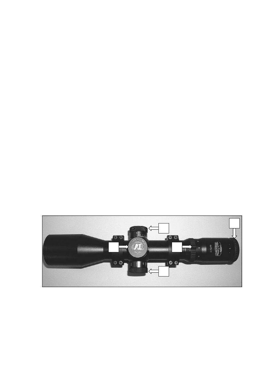
Fig. 18
Schmidt und Bender 3-12x50 MKII 0.2 MRAD Telescope
A Windage Adjustment Turret
D Magnification Ring
B Elevation Adjustment Turret
E Dioptre Adjustment Ring
C Parallax Adjustment Turret
C
B
A
E
D
Accuracy International Ltd.
39
8.2
AI Reticule
8.2.1 The reticule’s lines, graduations and MIL dots are accurately positioned and
dimensioned in order to serve as angular references.
The marks can be used as a guide to calculate distances, widths, heights and
angles and they also can be used to aim off for wind velocity or moving targets.
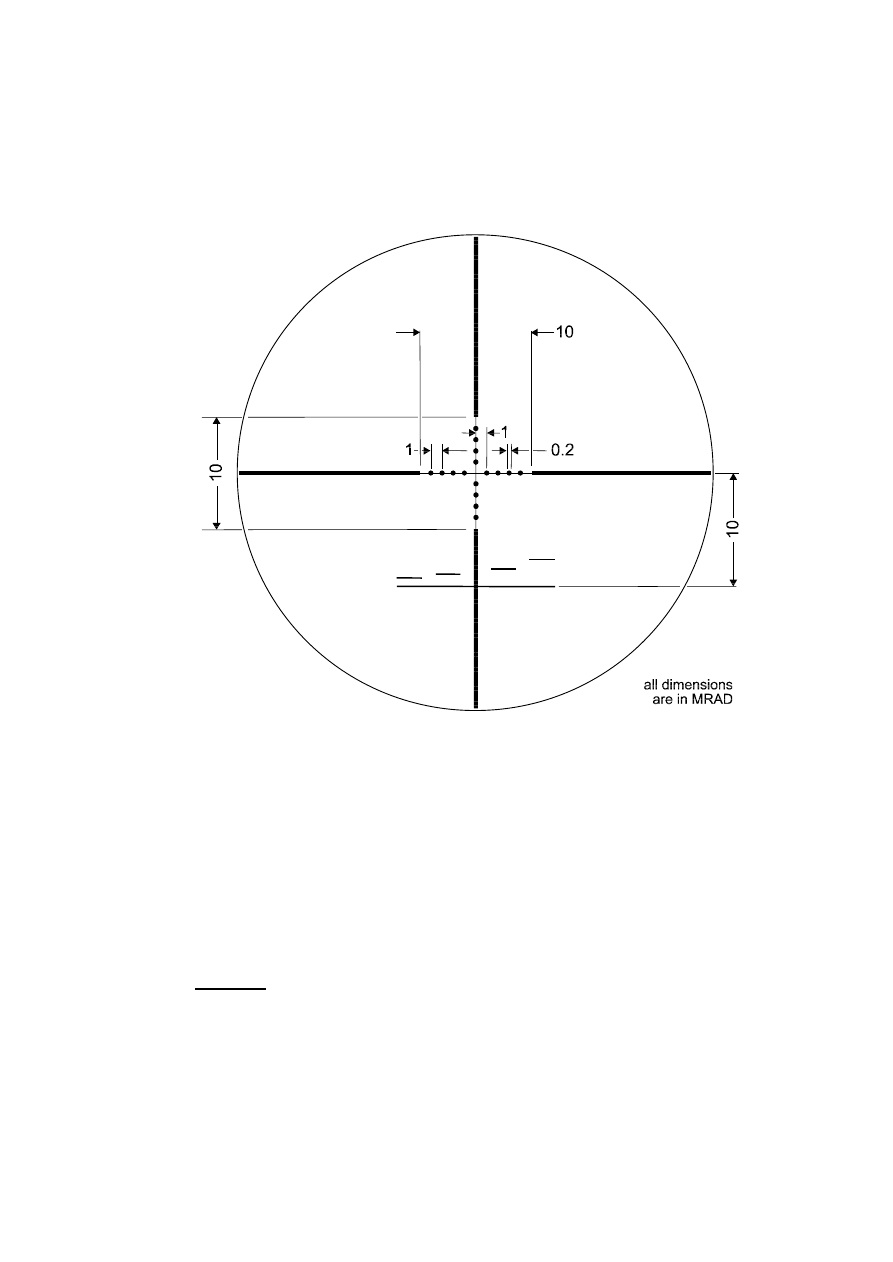
Fig. 19 AI Reticule
8.2.2 1 MRAD subtends 1 m at 1000 m. Therefore; the 0.2 MRAD dots on the reticule
subtend 20 mm at 100 m.
The spacing between the dots is 1 MRAD or 100 mm at 100 m.
The thick bars are spaced 10 MRAD apart and are thick enough to enable sighting
and "centring" of the target in bad light conditions.
8.2.3 To convert Mil-dot to minutes of angle, multiply the mils by 3.438
Example
5 mils x 3.438 = 17.19 MOA
AW50 Users Manual
40
250
200
150
100
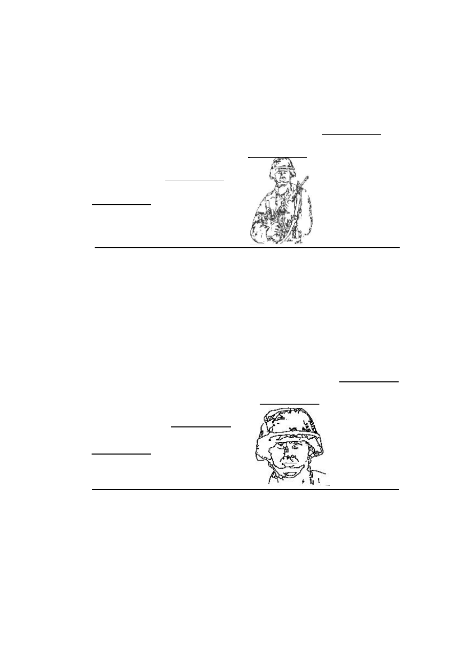
8.2.4 10 MRAD below the horizontal line is a base line and 4 stadia for use as a dual-
purpose range finder.
8.2.5 The stadia can be used to equate 1 m at distances of 400, 600, 800 and 1000 m
respectively, which is approximately the distance between the top of a man’s
helmet and his belt (Fig. 20).
Fig. 20 Range Finding Stadia (400 – 1000 m)
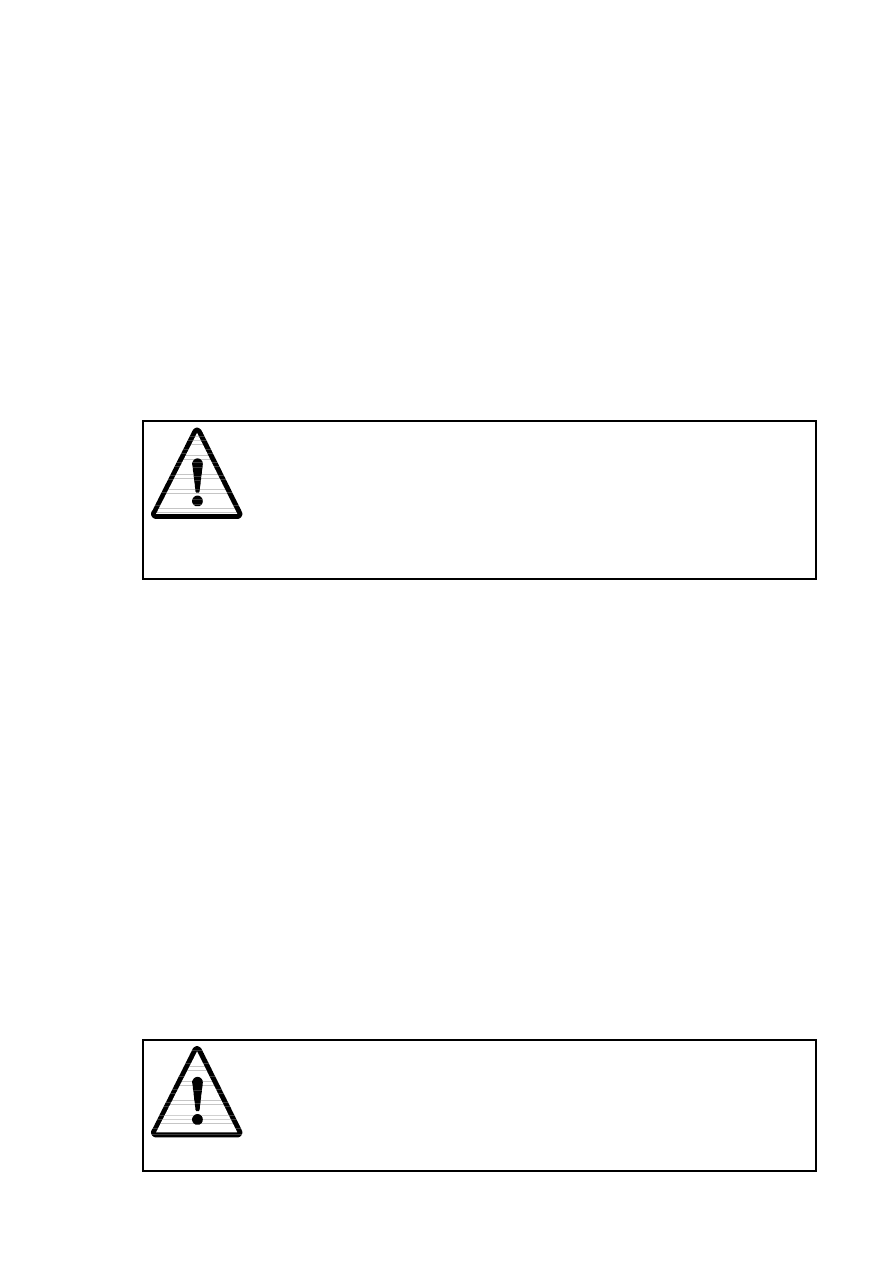
8.2.6
The stadia can also be used equate 250 mm at distances of 100, 150, 200 and 250
m respectively, which is approximately the depth of a mans head (Fig0 21).
Fig. 21 Range Finding Stadia (100 – 250 m)
1000
800
600
400
Accuracy International Ltd.
41
8.3
Eye Relief
8.3.1 The eye relief of the telescopic sight 3-12 x 50 MK II is set by the factory.
Since the bolt opening distance determines the head position on the cheekpiece,
the eye relief remains constant.
8.4
Eye Relief Adjustment
8.4.1 To adjust the eye relief, adopt the prone firing position.
8.4.2 Adjust the bipod legs to suite the terrain.
8.4.3 With the cheek on the cheekpiece the distance between eye and eyepiece should
be approximately 8 cm.
8.4.4 Where adjustment of the eye relief is required, loosen the three scope mount
screws and move the sight / mount assembly forward or rearwards to the next
position on the Picatinny rail.
8.4.5 Before re-tightening the mount securing screws ensure that the mount’s recoil lugs
are pushed forward against the back of the slot in the rail.
8.4.6
CAUTION
It is recommended that the scope is re-zeroed following any changes
to its position.
Do not adjust the eye relief by unscrew the clamp-securing screws
and slide the telescopic sight within its mount
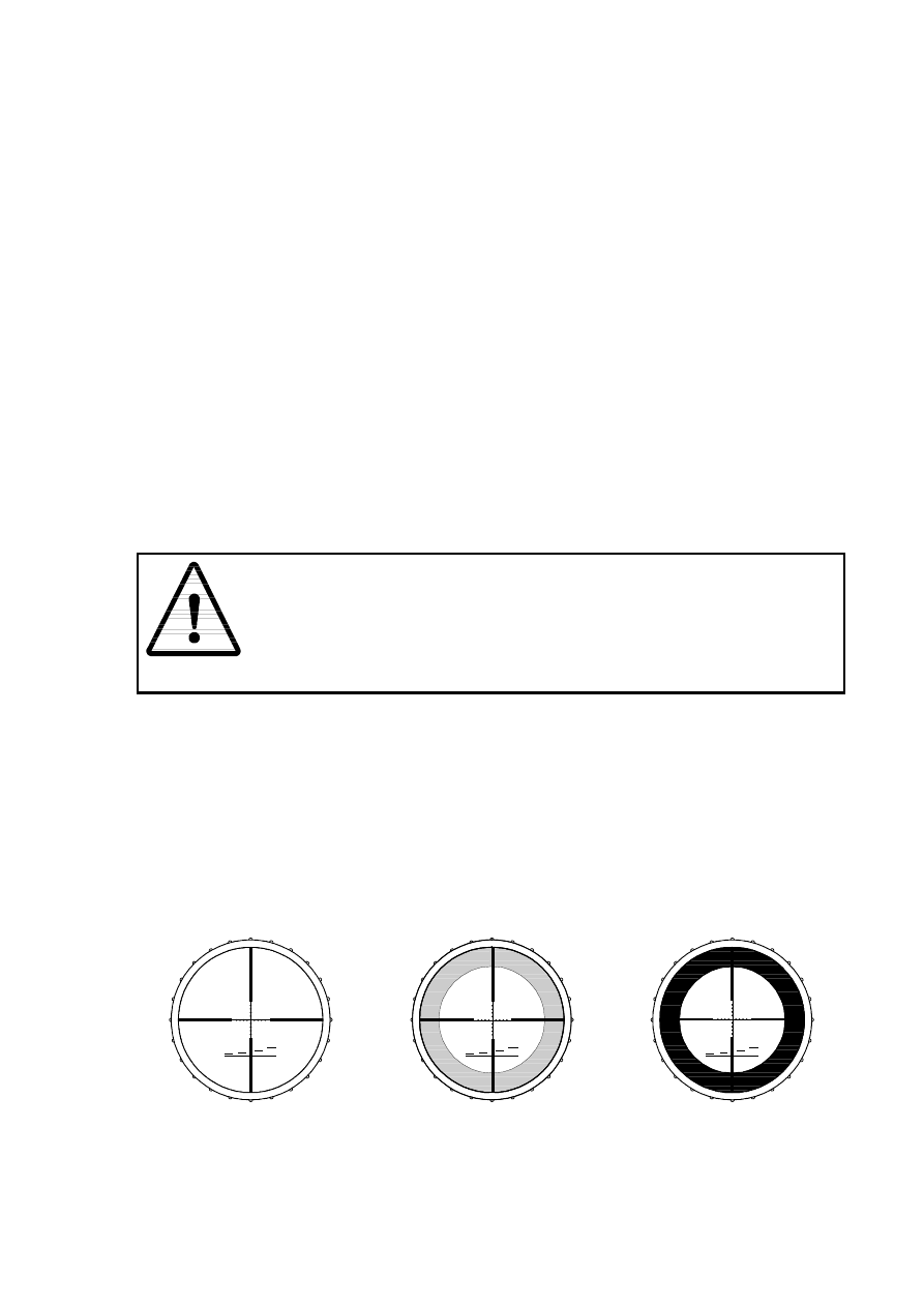
8.4.7 When the distance between the eye and the eyepiece is too short, a shadow is
produced at the extreme edges of the reticule and the field of view will be narrower
(Fig. 22 (b)).
When the distance between the eye and the eyepiece is too long, the extreme
edges of reticule are not visible and the field of view will be narrower (Fig. 22 (c)).
When the distance between the eye and the eyepiece is correct (approximately 7
cm), the whole of the reticule and the full field of view will be visible (Fig. 22 (a)).
(a) (b)
(c)
Fig. 22 Eye Relief

AW50 Users Manual
42
8.5
Eyepiece Dioptre Adjustment
8.5.1 A user with perfect sight will obtain a sharp image when the dot directly opposite
the 0 position, however most users will need to adjust the dioptre to suit their eye
8.5.2 To adjust the dioptre, set the zoom to full power.
8.5.3 Whilst looking through the telescope, turn the eyepiece as far left as possible. Then
turn it to the right until the reticule becomes both sharp and in focus.
8.6
Elevation Adjustment
8.6.1 The Elevation drum is the turret located on the top of the telescope.
8.6.2 It is used to apply aiming corrections in relation of the target range.
8.6.3 It has two scales: -
•
Lower scale is graduated from 0 to 22 MRAD.
•
Upper scale is graduated from 1 to 15 (corresponding respectively to 100 m
and 1500 m).
8.6.4 The upper scale provides an indication that the range has been correctly applied.
8.7
Windage Adjustment
8.7.1 The Windage drum is the turret located on the right hand side of the telescope.
8.7.2 It is used to apply aiming corrections in relation to the wind velocity.
8.7.3 It has one scale graduated from 0 to 6 MRAD to the left and from 0 to 6 MRAD to
the right.
8.8
Parallax Adjustment
8.8.1 The Parallax drum is the third turret on the left hand side of the telescope. This
feature allows the user to adjust the telescopic sight’s parallax without having to
take his eye of the target.
8.8.2 The range of adjustment is between 50 and 1000 m with an infinity marking.
8.8.3 If the distance is known, turn the drum so that the desired distance aligns with the
index point on the turret.
8.8.4 If the distance is unknown, set the zoom to full power.
8.8.5 Whilst looking through the telescope, move the parallax drum in the direction of the
roughly estimated distance until the image is at its as sharpest.
8.8.6 Now purposely move your eye up and down in the area of the exit pupil whilst
simultaneously correcting the parallax compensation drum until no movement is
visible between the reticule’s centre and the target.
Note: -
This may also be used for basic range finding.
Accuracy International Ltd.
43
9.0 User Maintenance – Telescope
9.1
General
9.1.1
The telescope is non-user maintainable. Under no circumstances should the user
conduct any more maintenance other than routine cleaning of its external
surfaces, the object glass and eye lens.
9.1.2
A qualified armourer should carry out all further maintenance. If doubt users
should seek the armourer’s advice.
9.2
Cleaning The Telescope
9.2.1
It is not necessary to remove the telescope from the rifle to clean it.
9.2.3
The lenses are the most important and most easily damaged part of the sight.
9.2.4
CAUTION
The protective caps should always be fitted when the sight is not in
use.
Lens should not be touched with anything except the recommended
cleaning materials.
When cleaning the lenses, always use a gentle circular motion,
working from the centre outwards.
9.2.5
To clean the lenses, remove the caps and sunshade (where fitted).
9.2.6
Large pieces of debris can be removed using a soft lens brush.
9.2.7
Where the brush fails to remove debris adhered to the lens’ surface, it should be
washed in soapy water to gently loosen and wash away the deposits.
9.2.8
The lens should then be wiped dry with a clean lens cloth.
9.2.9
Spots and stains can be removed by wiping the affected area with clean lens cloth
or disposal lens tissues wetted with a drop of methylated sprits.
9.2.10 Dust and smears are removed by breathing gently on the lens before carefully
polishing with a clean lens cloth or disposal lens tissues.
9.2.11 Following cleaning, replace the caps and sunshade (where fitted).
9.2.12 The scope’s body should be cleaned by a wipe over with a clean cloth.
9.2.13 When it is necessary to remove the sight from the rifle, the opportunity should be
taken to lightly oil the sight retaining screws and the mounting bracket after it has
been cleaned.
9.2.14
CAUTION
Ensure no oil comes into contact with the surface of the lenses.

AW50 Users Manual
44
10.0 Accuracy & Ammunition
10.1.1
All of Accuracy International’s sniper rifles are capable of very fine accuracy and
consistent first shot capability.
However, this performance is reliant on the quality and capability of the
ammunition used.
No matter how good the rifle is it will only shoot to the capability of the
ammunition.
For optimum results Match grade ammunition with specified accuracy capability
should be used.
11.0 User Tips
Obtain a shooting position where the bolt can be manipulated without head
movement and which minimises rifle movement.
Practice movements that are slow and smooth when using the rifle as a hide may
be compromised by rapid, jerky movements.
Ensure that all the rifle’s support points (bipod and third leg) are in contact with
the ground to minimise pulse beat.
When using the bipod, always push into the bipod so that on firing the rifle recoils
naturally (without resistance) about the ball joint.
Pulling back on the bipod can give serious elevation at the target, especially on
soft ground.
When holding the breath during firing it is better to exhale rather than inhale.
This reduces ground pressure on the abdomen and reduces pulse.
Press the thumb of the right hand on top of the action to aid leverage when
opening the bolt to assist the removal of tight extractions.
ALWAYS ensure that the bolt is fully closed before reopening so that any live
round that is already in the chamber, will be gripped by the extractor and ejected.
When cycling the bolt for repeat shots, ALWAYS ensure that bolt is retracted
fully rearwards i.e. to touch the bolt stop, to minimise the chance of a misfeed.
Watch for the fall of the shot in case a quick follow up shot is necessary.

Accuracy International Ltd.
45
12.0 Customer Communications
12.1.1
Accuracy International welcomes your feedback on our products and service,
both negative and positive.
We are able to offer Service/ Repair and Spares packages.
Our Sales team are available to discuss how we may be of assistance to you
now and in the future
UK & Rest Of World (Excluding USA)
Accuracy International Ltd.
P.O. Box 81
Portsmouth
Hampshire
PO3 5SJ
United Kingdom
Tel:
+44 (0)23 9267 1225
Fax: +44 (0)23 9269 1852
Email: precision@accint.org
USA Only
Accuracy International North America
P.O. Box 5267
Oak Ridge
TN 37831
USA
Tel:
(865) 482-0330
Fax: (865) 482-0336
Email: AINA@accuracyinternational.org

AW50 Users Manual
46
13.0 Shooting Log
Rifle Serial No.
Barrel Serial No.
Date
Daily
Rounds
Cumulative
Rounds
Comments
Date
Daily
Rounds
Cumulative
Rounds
Comments
Wyszukiwarka
Podobne podstrony:
OPERATOR MANUAL LONG RANGE SNIPER RIFLE CALIBER 50, M107
Mauser 98k Model 48 Rifle (8mm) Manual
Materiały dydaktyczne, TABLICA 50, Luteranizm
Colt Light Rifle Owner s Manual Rev 5 12 00
Colt Light Rifle Owner s Manual Orig
Swiatla nawigacyjne, manuale materiały notatki pokład ow, Nawigacja
Plywy, manuale materiały notatki pokład ow, Nawigacja
Wiatr przywodny, manuale materiały notatki pokład ow, Meteorologia
drukowanie 40 50, materiały fizjo, Fizjologia wysiłku fizycznego
prawo morskie, manuale materiały notatki pokład ow, kurs Kapitański
Zestaw 50 Hanka Cywińska, materiały farmacja, Materiały 3 rok, Od Ani, biochemia, biochemia, opracow
41-50, Prywatne, Budownictwo, Materiały, I semestr, geologia - wykład
Etapy kształtowania się sprawności manualnej, PEDAGOGIKA - materiały
więcej podobnych podstron