
Installation and
Introduction to
Programming
LightJockey
Version 2.5 for
Windows 95/98/Me/2000/XP

© 1998 - 2003 Martin Professional A/S, Denmark.
All rights reserved. No part of this manual may be
reproduced, in any form or by any means, without
permission in writing from Martin Professional A/S,
Denmark.
Printed in Denmark.
P/N 35002504 Revision E

3
Installation ................................................................................................ 5
Hardware installation ....................................................................................................................... 5
Windows 2000 or Windows XP ................................................................................................. 5
Installing the LightJockey PCI card on a Windows 2000/XP system ................................. 6
Installing the LightJockey 4064 ISA card on a Windows 2000/XP system ....................... 8
Installing the LightJockey PCMCIA interface on a Windows 2000/XP system .............. 13
Installing the LightJockey USB/DMX interface on a Windows 2000 system .................. 13
Installing the LightJockey USB/DMX interface on a Windows XP system ..................... 17
Windows 95, Windows 98, or Windows ME ........................................................................... 23
Installing the LightJockey PCI card on a Windows 95/98/ME system ............................. 23
Installing the LightJockey 4064 ISA card on a Windows 95/98/ME system ................... 25
Installing the LightJockey ADP parallel port interface on a Windows 95/98/ME system 28
Installing the LightJockey PCMCIA interface on a Windows 95/98/ME system ............ 29
Installing the LightJockey USB/DMX interface on a Windows 95/98/ME system .......... 29
Notes on removing the PCI/ISA driver .................................................................................... 33
Software installation ...................................................................................................................... 34
Hardware configuration ................................................................................................................. 38
Connecting the serial data link....................................................................................................... 40
Interface XLR cable connections.............................................................................................. 40
LightJockey PCI 512 and 4064 ISA DJ cards ................................................................... 40
LightJockey PCI 2048 and 4064 ISA Club cards .............................................................. 40
DMXADP interface ........................................................................................................... 41
PCMCIA interface ............................................................................................................. 41
USB interface .................................................................................................................... 41
Connecting to fixtures .............................................................................................................. 41
Tips for building a trouble-free serial link................................................................................ 41
Introduction to programming ..................................................................42
Identifying the controls .................................................................................................................. 43
Main screen............................................................................................................................... 43
Sequence toolbar....................................................................................................................... 43
Cue toolbar ............................................................................................................................... 44
Cue List toolbar ........................................................................................................................ 44
Fixture toolbar .......................................................................................................................... 45
Configuring fixtures....................................................................................................................... 46
Example: Configure 2 MAC 600s ............................................................................................ 46
Configuring the desktop................................................................................................................. 48
Example: Place 2 MAC 600s on desktop ................................................................................. 48
Striking lamps ................................................................................................................................ 49
Example: Strike MAC 600s...................................................................................................... 49
Programming cues ......................................................................................................................... 50
Cue building blocks .................................................................................................................. 50
Bottom to top cue execution ..................................................................................................... 50
Outline of programming steps .................................................................................................. 51
Creating new cues..................................................................................................................... 51

4
Creating and editing sequences................................................................................................. 51
Selecting fixtures ...................................................................................................................... 52
Programming effects................................................................................................................. 52
Setting the Off/Snap/Fade control ............................................................................................ 52
Setting scene and fade times ..................................................................................................... 53
Adding, inserting, and deleting scenes ..................................................................................... 53
Saving sequences ...................................................................................................................... 53
Adding sequences to a cue........................................................................................................ 54
Saving cues ............................................................................................................................... 54
Example: Programming a cue................................................................................................... 54
Step 1: Program shutter/dimmer sequence ........................................................................ 54
Step 2: Add sequence to cue .............................................................................................. 56
Step 3: Program color sequence ........................................................................................ 56
Step 4: Program movement sequence ................................................................................ 59
Step 5: Edit movement sequence ....................................................................................... 62
Step 6: Save the cue ........................................................................................................... 63
Step 7: Edit the cue ............................................................................................................ 64
Additional cue operations ......................................................................................................... 66
2532 Direct Access Controller ....................................................................................................... 66

5
Installation
To install LightJockey, perform the following steps:
1.
“Hardware installation” on page 5
2.
“Software installation” on page 34
3.
“Hardware configuration” on page 38
4.
“Connecting the serial data link” on page 40
This guide assumes that the installation steps will be performed in this order, but this is
not a requirement. It is possible to install the LightJockey software first, for example.
Hardware installation
The LightJockey controller software comes bundled with hardware to enable DMX
transmission to control DMX-512 fixtures from your PC. This hardware must be installed
and configured within LightJockey before use.
Follow the procedure that applies to the operating system that your PC is running:
•
“Windows 2000 or Windows XP” on page 5, or
•
“Windows 95, Windows 98, or Windows ME” on page 23.
Windows 2000 or Windows XP
Support for Windows 2000 and Windows XP was introduced in LightJockey version 2.0.
Ensure that you have the appropriate version, or later, before starting these procedures.
The version number is printed on the CD. Updates can be downloaded from the Service
pages at http://www.martin.dk
In order to install the required drivers, you must be logged on to Windows 2000 with
administrator rights.
LightJockey supports four types of hardware under Windows 2000/XP:
•
LightJockey PCI card. Follow the steps under “Installing the LightJockey PCI card on
a Windows 2000/XP system” on page 6
•
LightJockey 4064 8-bit ISA card. Follow the steps under “Installing the LightJockey
4064 ISA card on a Windows 2000/XP system” on page 8
•
LightJockey PCMCIA interface. Follow the steps under “Installing the LightJockey

6
•
LightJockey USB interface. Follow the steps under “Installing the LightJockey
USB/DMX interface on a Windows 2000 system” on page 13, or “Installing the
LightJockey USB/DMX interface on a Windows XP system” on page 17.
Installing the LightJockey PCI card on a Windows 2000/XP sys-
tem
The LightJockey PCI card comes in two flavors - the PCI 2048 channel version and the
PCI 512 channel version. The installation process is identical for both types.
Support for the LightJockey PCI cards was introduced in LightJockey version 2.1. Ensure
that you have this version, or later, before starting these procedures. The version is printed
on the CD. Updates can be downloaded from the Service pages at http://www.martin.dk
The card can be damaged by static electricity. Release static electric charges before
handling the hardware by touching a grounded metal object, and always avoid touching
sensitive electronic components.
Installing the card
To install the LightJockey PCI card:
1.
Turn off the computer.
2.
Disconnect the power cord. Failure to unplug the cord could result in injury to you or
damage to the computer.
3.
Remove the computer cover.
4.
Find an available PCI expansion slot and remove its cover plate from the back of the
computer chassis.
5.
Holding the card by the bracket and corner, push the card's copper contacts into the
expansion slot. Ensure that the card is correctly seated in the PCI slot.
6.
Fasten the card to the chassis.
7.
Replace the cover and reconnect the power cord.
8.
Connect the DMX output cable(s) to the card. There:
•
Are 2 connectors on the PCI 2048 version: The top connector has DMX output
for DMX links 1 and 2; the bottom connector has DMX output for DMX links 3
and 4, or alternatively DMX output for DMX link 3 and input for DMX in.
•
Is 1 connector in the PCI 512 version, supporting both DMX input and output.
9.
Restart the computer. The LightJockey PCI card is Plug and Play compatible.
Windows will automatically detect the card once it has been installed and the
Found
New Hardware
wizard will start.
10.
Use the wizard to locate the
4064PCI.inf
file which is located in the
HardwareDrivers\PCI_ISA
folder on the LightJockey CD-ROM (or in the same
sub-folder of the
Martin LightJockey
folder, if you have already installed
LightJockey).
7
11.
Once the driver has been installed and Windows has started, right-click on
My
Computer
, and then click
Properties
to open the
System Properties
dialog box.
12.
Click
Hardware
.
13.
Click
Device Manager...
to open the
Device Manager
dialog box.
14.
Check that the device
Martin PCI4064: DMX PCI Card
appears under
Martin
devices
.
15.
Go to the next section, “Installing the PCI/ISA driver” on page 7.
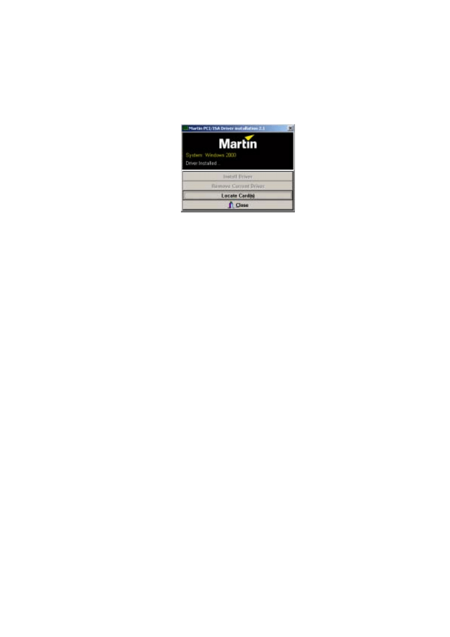
Installing the PCI/ISA driver
Install the PCI/ISA driver:
1.
Using Windows Explorer, open the
HardwareDrivers\PCI_ISA
folder on the
CD-ROM, or if you have already installed LightJockey, in the same sub-folder of the
Martin LightJockey folder.
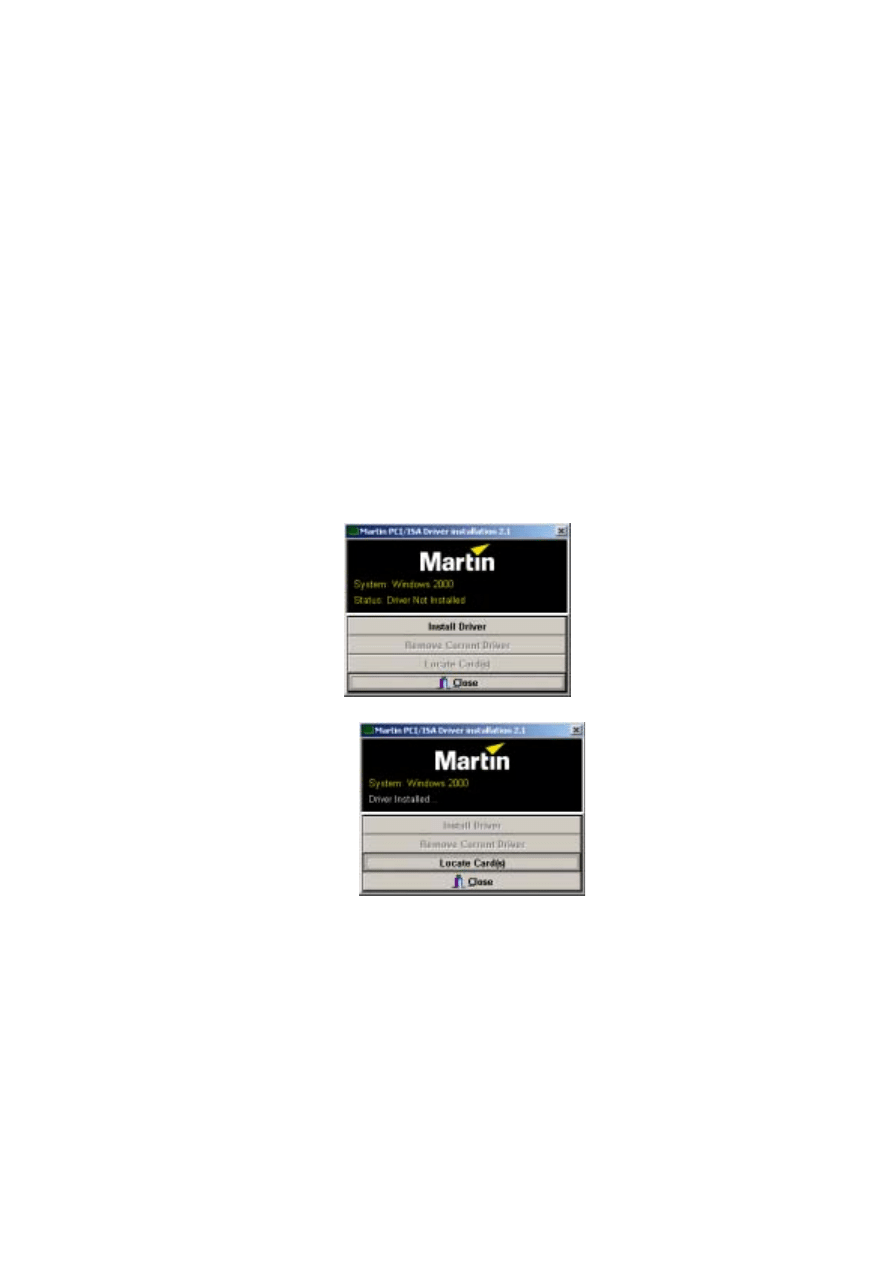
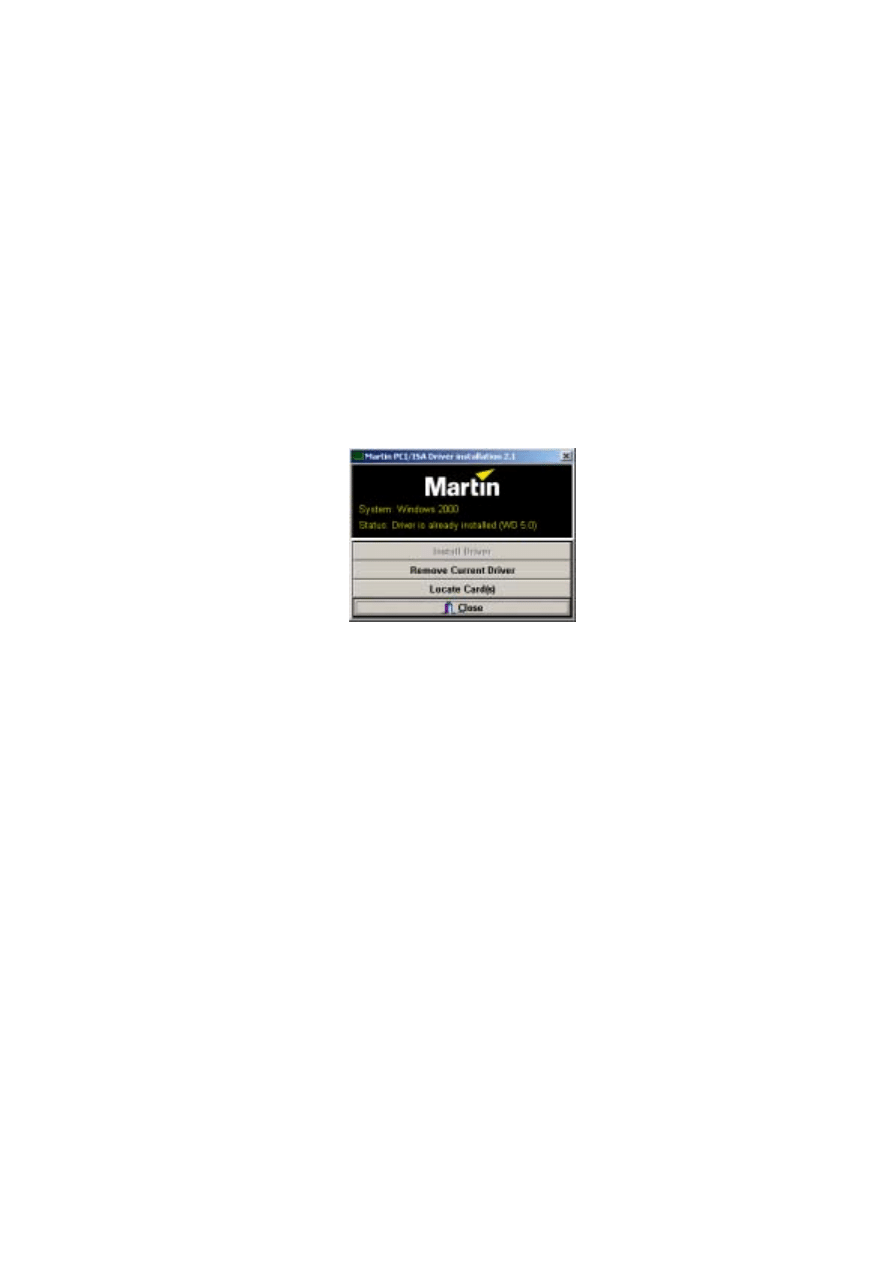
2.
Double-click the
Installer
application to start it. (If the driver has already been
installed then a message will appear indicting this).
3.
Click
Install Driver
.
4.
Click
Locate Card(s)
and any installed LightJockey ISA or PCI cards should appear.
5.
It is not necessary to restart Windows. Go to “Software installation” on page 34.
8
Installing the LightJockey 4064 ISA card on a Windows
2000/XP system
The LightJockey 4064 ISA card comes in two flavors - the 2048 DMX channel Club
version and the 512 channel DJ version. The installation process is identical for both
types.
The card can be damaged by static electricity. Release static electric charges before
handling the hardware by touching a grounded metal object, and always avoid touching
sensitive electronic components.
Setting the DIP switch on the card
The card’s DIP-switch setting is used to specify the location in memory that will be
allocated to the card. This may need to be adjusted. To find out:
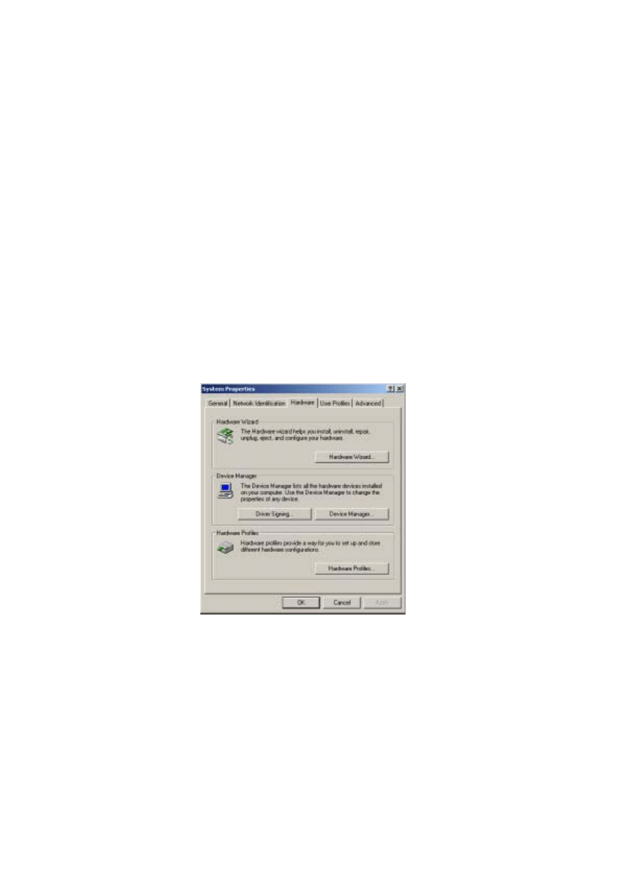
1.
From the Desktop, right-click
My Computer
and select
Properties
to open the
System Properties
window.
2.
Click
Hardware
to open the following page.
9
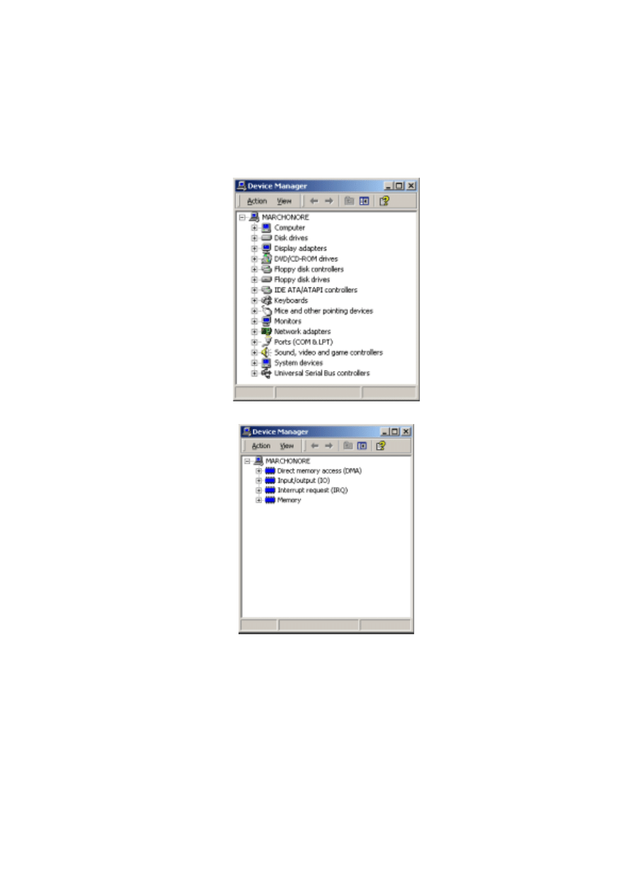
3.
Click
Device Manager
to open the following window.
4.
Select
View
→Resources by type
.
1 0
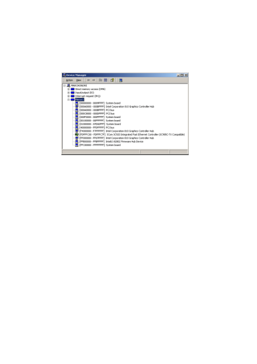
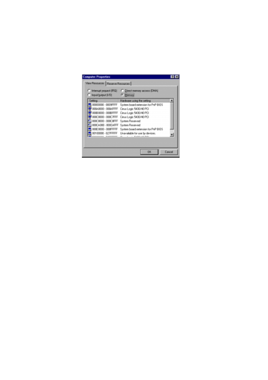
5.
Expand
Memory
to view a list similar to the one in the following illustration.
6.
If:
•
No device is allocated to the memory from 000D2000 to 000D2FFF, the card’s
default DIP-switch setting (pins 2 and 5 on) will work. You can now go to “Installing
the card” on page 12.
•
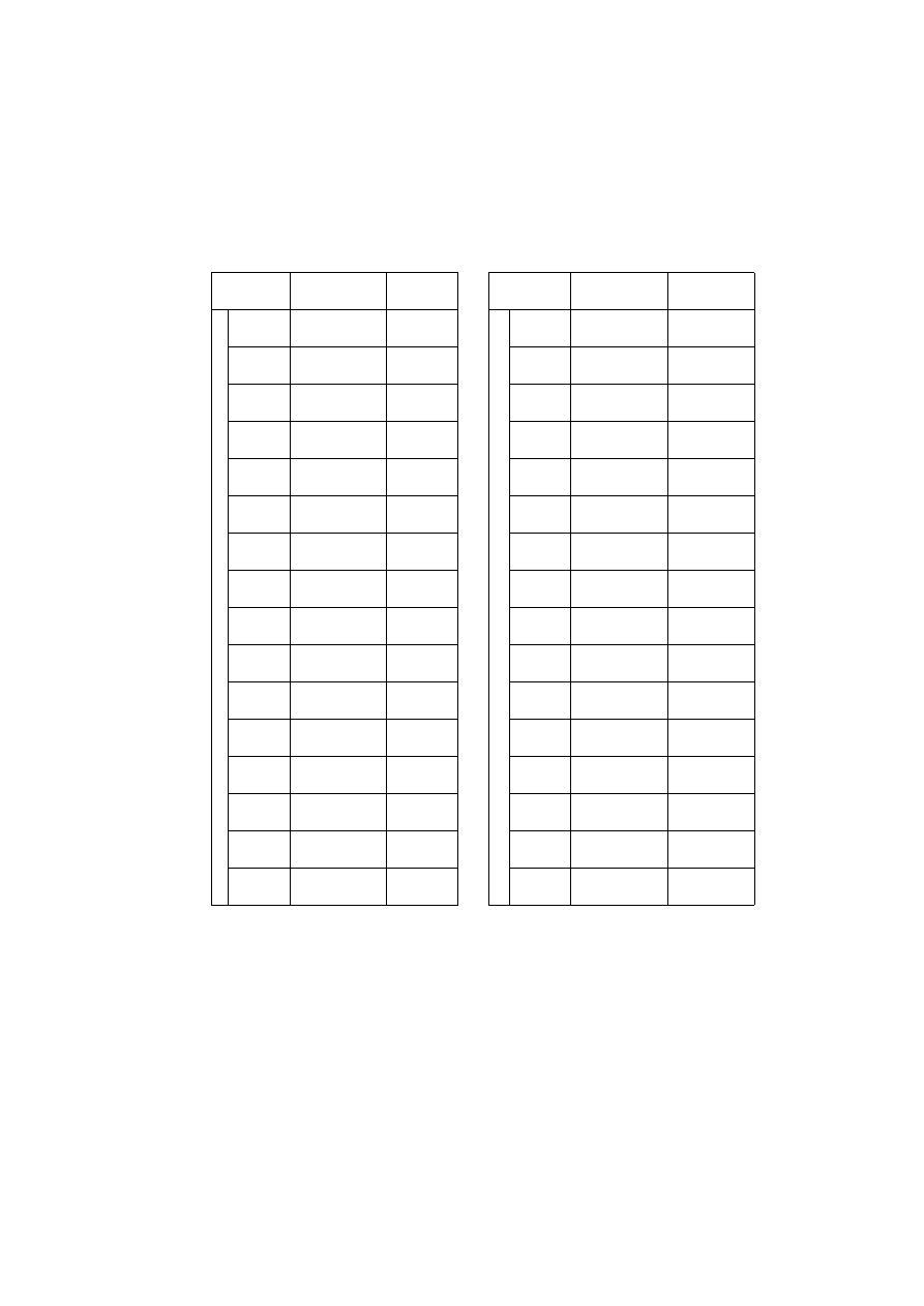
Any device is allocated to the memory from 000D2000 to 000D2FFF, use the
following table to locate a free block of memory and to set the DPI-switch pins
accordingly:

1 1
7.
Set the card’s DIP switch for the unoccupied memory block by moving the pins
indicated under “Pins On” to the ON position. Move all other pins to the off
position. Check that the correct DIP switches are ON, and that all other DIP
switches are OFF.
8.
Close the
Device Manager
window to proceed to “Installing the card” on page 12.
B l o c k
A d d r e s s
R a n g e
P i n s
O n
B l o c k
A d d r e s s
R a n g e
P i n s
O n
C SEGMENT
C0
000C0000
000C0FFF
None
D SEGMENT
D0
000D0000
000D0FFF
5
C1
000C1000
000C1FFF
1
D1
000D1000
000D1FFF
1, 5
C2
000C2000
000C2FFF
2
D2
000D2000
000D2FFF
2, 5
C3
000C3000
000C3FFF
1, 2
D3
000D3000
000D3FFF
1, 2, 5
C4
000C4000
000C4FFF
3
D4
000D4000
000D4FFF
3, 5
C5
000C5000
000C5FFF
1, 3
D5
000D5000
000D5FFF
1, 3, 5
C6
000C6000
000C6FFF
2, 3
D6
000D6000
000D6FFF
2, 3, 5
C7
000C7000
000C7FFF
1, 2, 3
D7
000D7000
000D7FFF
1, 2, 3, 5
C8
000C8000
000C8FFF
4
D8
000D8000
000D8FFF
4, 5
C9
000C9000
000C9FFF
1, 4
D9
000D9000
000D9FFF
1, 4, 5
CA
000CA000
000CAFFF
2, 4
DA
000DA000
000DAFFF
2, 4, 5
CB
000CB000
000CBFFF
1, 2, 4
DB
000DB000
000DBFFF
1, 2, 4, 5
CC
000CC000
000CCFFF
3, 4
DC
000DC000
000DCFFF
3, 4, 5
CD
000CD000
000CDFFF
1, 3, 4
DD
000DD000
000DDFFF
1, 3, 4, 5
CE
000CE000
000CEFFF
2, 3, 4
DE
000DE000
000DEFFF
2, 3, 4, 5
CF
000CF000
000CFFFF
1, 2, 3, 4
DF
000DF000
000DFFFF
1, 2, 3, 4, 5

1 2
Installing the card
To install the LightJockey 4064 ISA card:
1.
Turn off the computer.
2.
Disconnect the power cord. Failure to unplug the cord could result in injury to you or
damage to the computer.
3.
Remove the computer cover.
4.
Find an available ISA expansion slot and remove its cover plate from the back of the
computer chassis.
5.
Holding the card by the bracket and corner, push the card's copper contacts into the
expansion slot. Ensure that the card is correctly seated in the ISA slot.
6.
Fasten the card to the chassis.
7.
Replace the cover and reconnect the power cord.
8.
Connect the DMX output cable(s) to the card. There:
•
Are 2 connectors on the Club version: The top connector has DMX output for DMX
links 1 and 2; the bottom connector has DMX output for DMX links 3 and 4, or
alternatively DMX output for DMX link 3 and input for DMX in.
•
Is 1 connector in the DJ version, supporting both DMX input and output.
9.
You should now restart your computer and go to the following driver installation
procedure.
Installing the PCI/ISA driver
The LightJockey 4064 ISA card is not Plug and Play compatible. It is not possible for
Windows to automatically detect the card once it has been installed. A driver installation
program is supplied on the LightJockey CD-ROM.
1.
Using Windows Explorer, open the
HardwareDrivers\PCI_ISA
folder on the CD-
ROM, or if you have already installed LightJockey, in the same sub-folder of the
Martin LightJockey folder.
2.
Double-click the
Installer
application to start it. (If the driver has already been
installed then a message will appear indicting this).

1 3
3.
Click
Install Driver
.
4.
Click
Locate Card(s)
and any installed LightJockey ISA or PCI cards should appear.
5.
It is not necessary to restart Windows. Go to “Software installation” on page 34.
Note that once the card is installed it may not show up in the Windows 2000/XP
Device
Manager
. This can occur because of a driver problem, but will not prevent the
LightJockey or the LightJockey 4064 card from functioning correctly. If this occurs,
make a note of the memory address range that the card uses and when installing new
devices in the future, ensure that they do not use memory in this range.
Installing the LightJockey PCMCIA interface on a Windows
2000/XP system
The LightJockey PCMCIA interface provides two 512 channel DMX links. One link may
be used as a DMX input. For installation, please refer to the LightJockey PCMCIA
Adapter QuickStart User's Guide. Once you have installed the PCMCIA interface go to
“Software installation” on page 34.
Note that although the LightJockey PCMCIA interface is a “hot plug” interface (able to
be removed while Windows is running), do not remove and re-insert the interfaces while
LightJockey is running as the interfaces will not be re-initialized correctly. To re-
initialize the interfaces, restart LightJockey.
Installing the LightJockey USB/DMX interface on a Windows
2000 system
There are three types of LightJockey USB/DMX interface:
1.
Original LightJockey USB/DMX
2.
LightJockey USB/DMX II-in
3.
LightJockey USB/DMX II-out
Up to four LightJockey USB/DMX out (original models or version II) and one
LightJockey USB/DMX II-in interfaces can be connected to a PC. LightJockey version
2.5, or higher, is required.
1 4
Note regarding the Location of the USB driver
The guidelines in this section refer to the 'location of the USB driver' in several places.
The exact location of the driver files will depend on if what the installation is. If:
1.
The driver has been downloaded as a separate update, the driver files will be located
where they were unzipped to on the hard drive.
2.
LightJockey is installed/updated from a CD the driver are located on the CD in
\HardwareDrivers\USB2\
3.
The driver is updated from a downloaded release of LightJockey, run LightJockey
once to unpack compressed files. The driver files are now located in <LightJockey
Installation>\HardwareDrivers\USB2\
Before the LightJockey USB/DMX interface can be used with LightJockey, you must
install the correct USB device driver. Note that each of the three types of LightJockey
USB/DMX interface has their own driver:
•
Martin USB/DMX Interface (Unified Driver)
•
Martin USB/DMX Interface II - DMX Out (Unified Driver)
•
Martin USB/DMX Interface II - DMX In (Unified Driver)
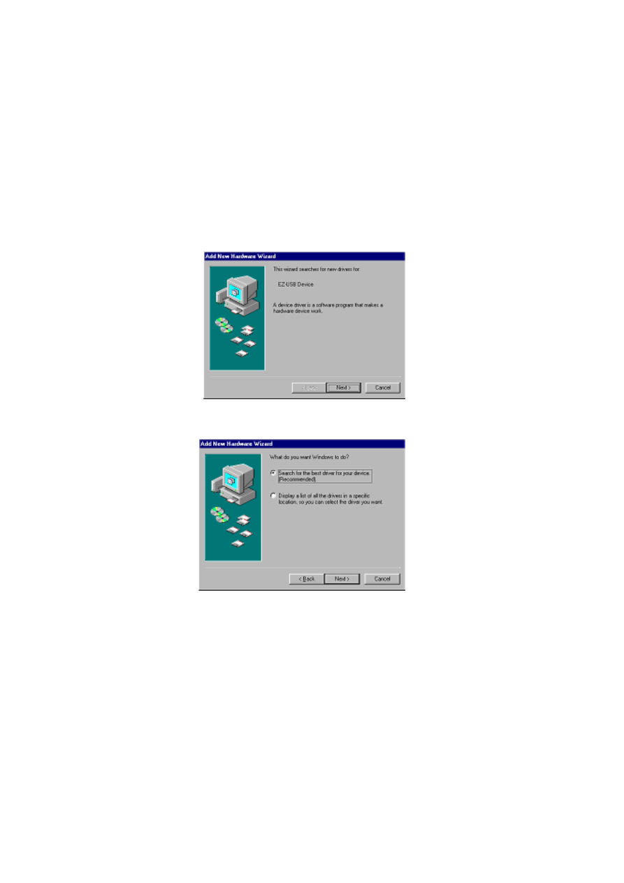
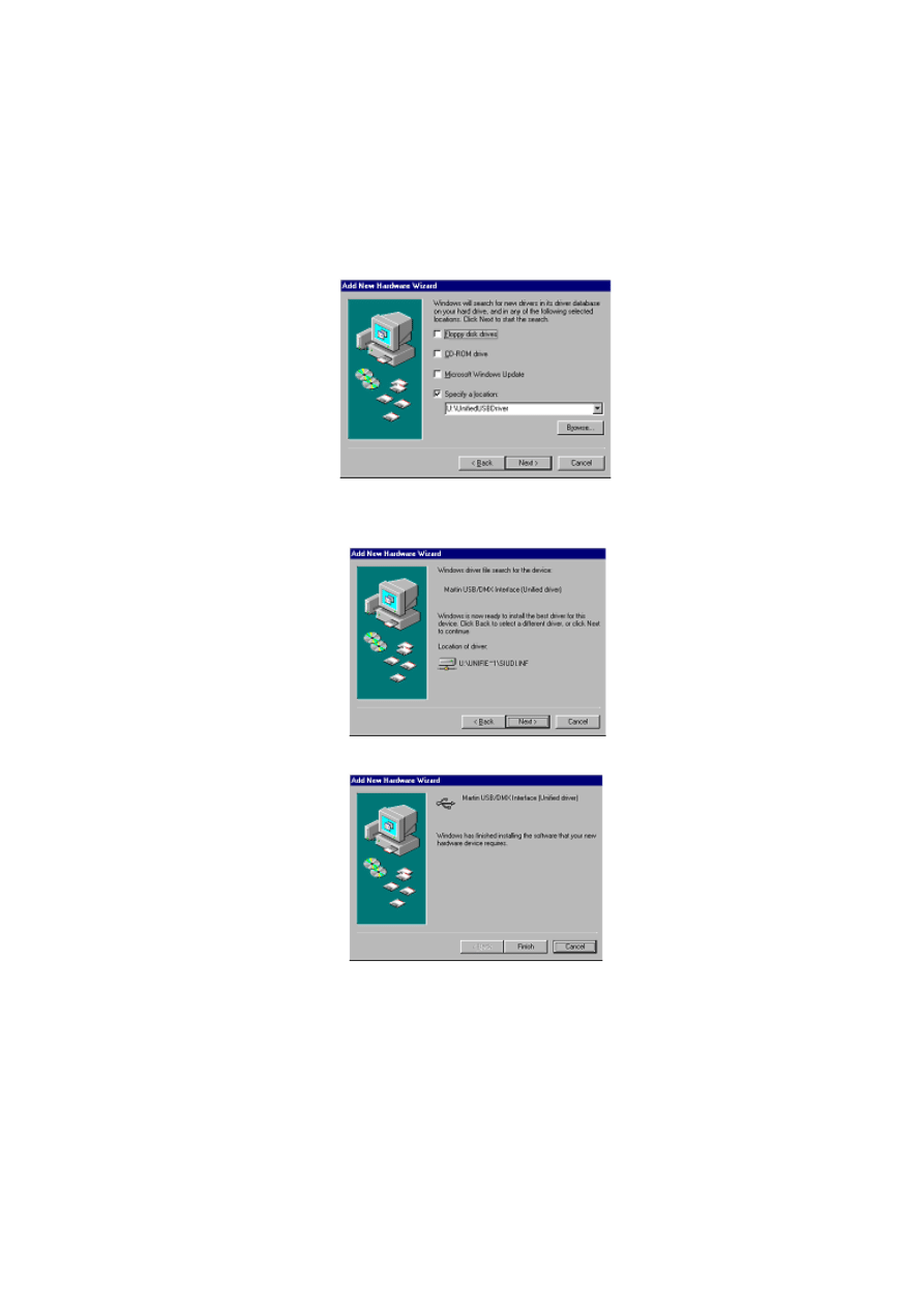
1.
Turn on the PC with all the interfaces attached.
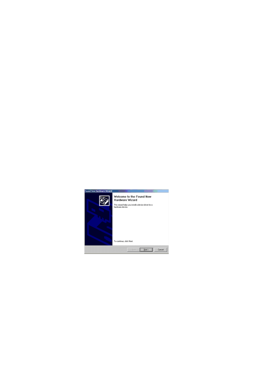
2.
Once Windows has detected an interface, the
Found New Hardware Wizard
will
appear, prompting for a driver for a EZ-USB device.
3.
Click
Next
.
1 5
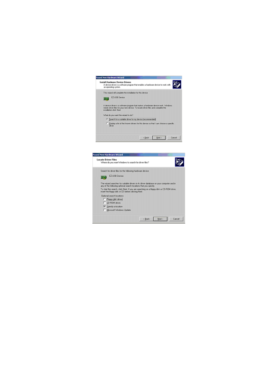
4.
Select
Search for a suitable driver for my device
, and then click
Next
.
5.
Select
Specify a location
and click
Next
.
6.
Click
Browse
to locate the folder with the driver. Click
OK
.
1 6
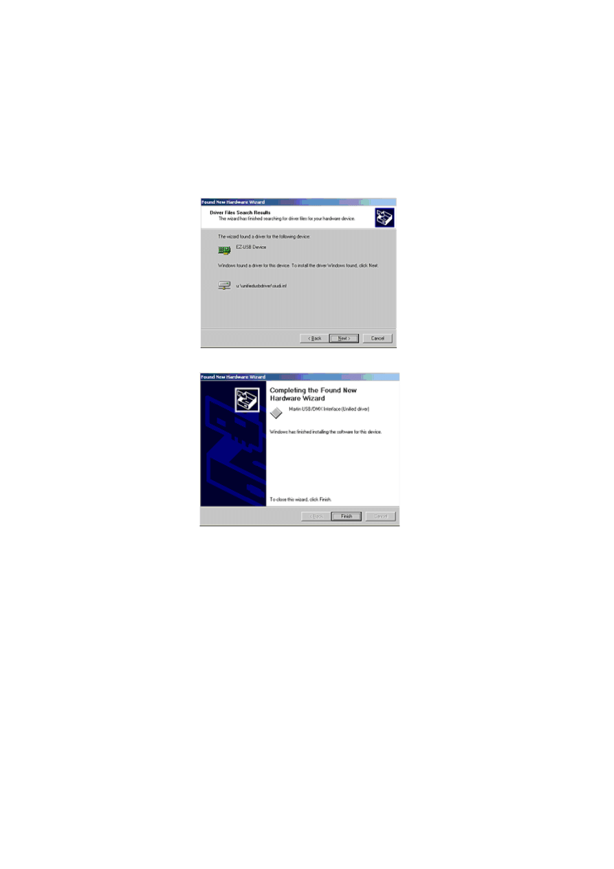
7.
If a suitable driver is found in the folder, the Wizard will list the driver name and
location. Check this information to ensure that the correct driver has been found.
Click
Next
.
8.
Windows will now install the driver, check that the device name has been updated.
9.
Click
Finish
and if additional LightJockey USB/DMX interfaces are present then
repeat this procedure from step 2 until a driver for each has been installed.
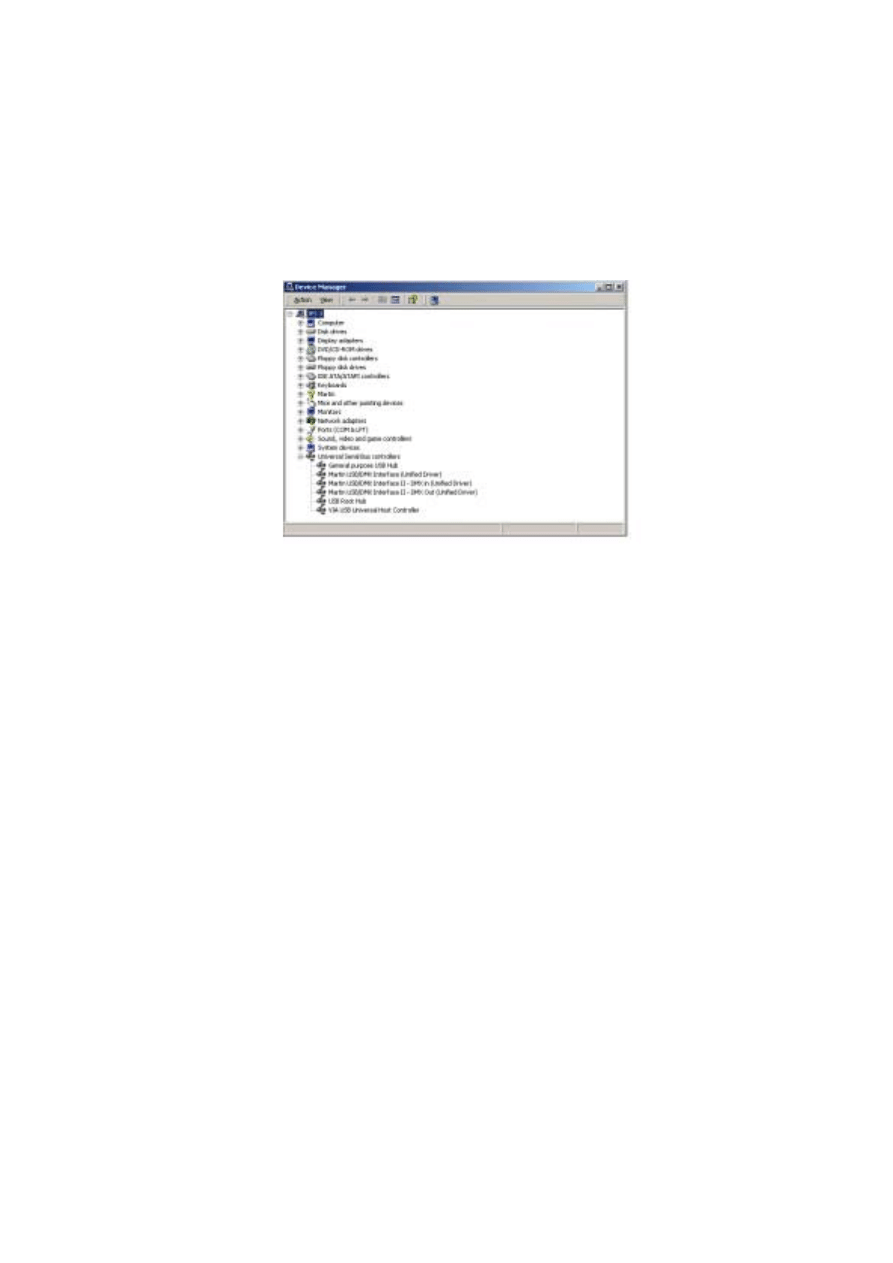
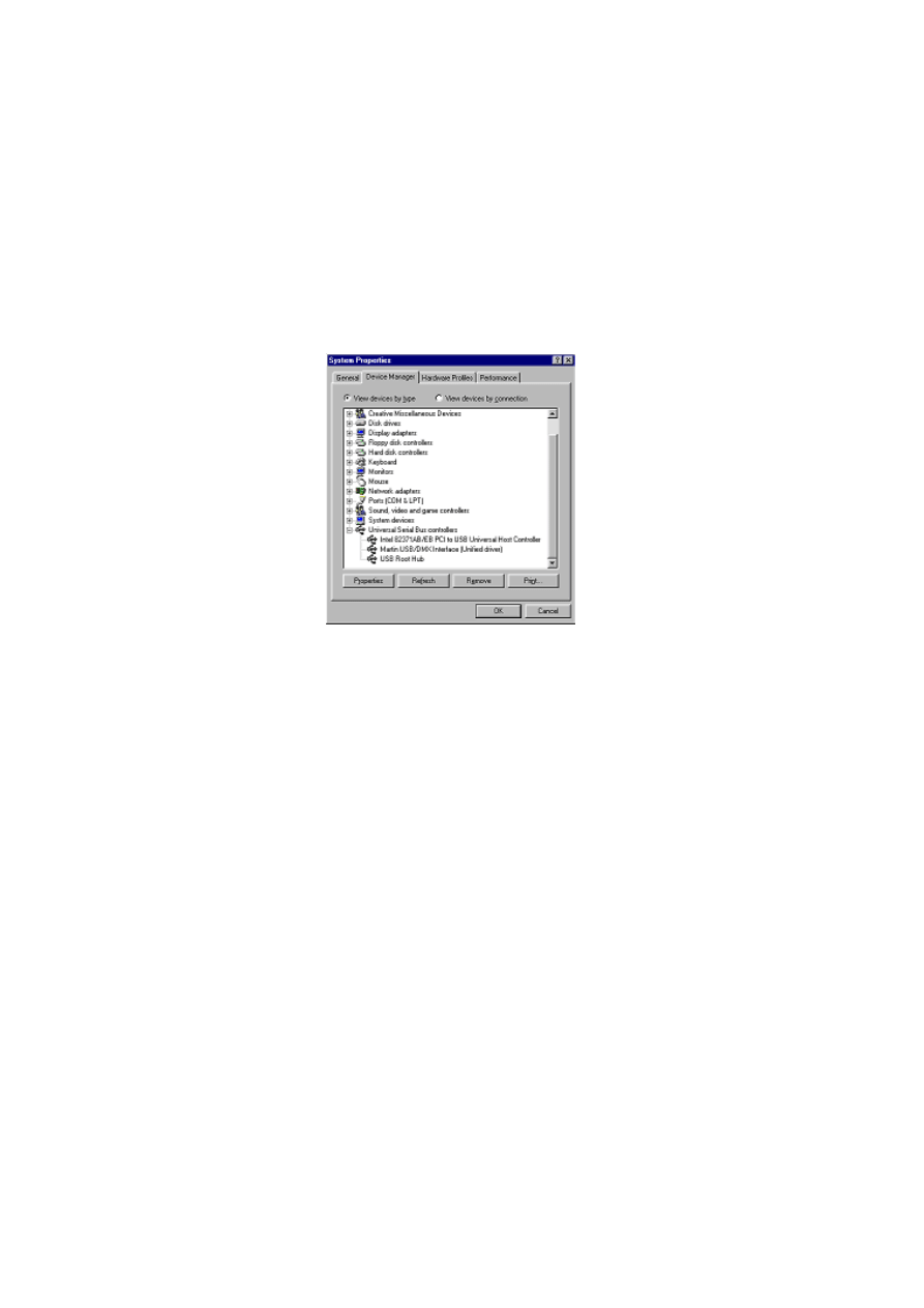
10.
To ensure that the drivers are properly installed and in working order open the
device manager by right-clicking
My Computer
, select properties from the popup
menu. Select the
Hardware
tab, and then click
Device Manager
.
1 7
11.
Expand the
Universal Serial Bus Controllers
entry and check that the correct
driver is displayed (without an exclamation mark, as this indicates that there is a
problem.
To ensure that LightJockey routes DMX data to the correct interface when
operating with multiple LightJockey USB/DMX interfaces, always connect:
•
All USB/DMX interfaces to the USB port(s) on the PC before applying power to
the PC. This includes a first time setup and configuration.
•
Each USB/DMX interface to the same physical USB port on the PC.
Installing the LightJockey USB/DMX interface on a Windows
XP system
There are three types of LightJockey USB/DMX interface:
1.
Original LightJockey USB/DMX
2.
LightJockey USB/DMX II-in
3.
LightJockey USB/DMX II-out
Up to four LightJockey USB/DMX out (original model or version II) and one
LightJockey USB/DMX II in interfaces can be connected to a PC. LightJockey version
2.5, or higher, is required.
Note regarding the Location of the USB driver
The guidelines in this section refer to the 'location of the USB driver' in several places.
The exact location of the driver files will depend on if what the installation is. If:
1.
The driver has been downloaded as a separate update, the driver files will be located
where they were unzipped to on the hard drive.
1 8
2.
LightJockey is installed/updated from a CD the driver are located on the CD in
\HardwareDrivers\USB2\
3.
The driver is updated from a downloaded release of LightJockey, run LightJockey
once to unpack compressed files. The driver files are now located in <LightJockey
Installation>\HardwareDrivers\USB2\
Before the LightJockey USB/DMX interface can be used with LightJockey, you must
install the correct USB device driver. Note that each of the three types of LightJockey
USB/DMX interface has their own driver:
•
Martin USB/DMX Interface (Unified Driver)
•
Martin USB/DMX Interface II - DMX Out (Unified Driver)
•
Martin USB/DMX Interface II - DMX In (Unified Driver)
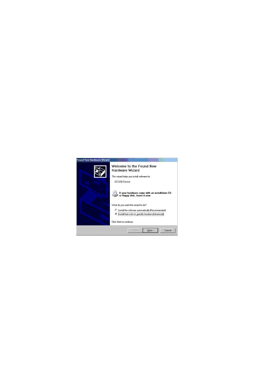
1.
Turn on the PC with all the interfaces attached.
2.
Once Windows has detected an interface, the
Found New Hardware Wizard
will
appear, prompting for a driver for a EZ-USB device).
3.
Select
Install from a list or specific location
, then click
Next
.
1 9
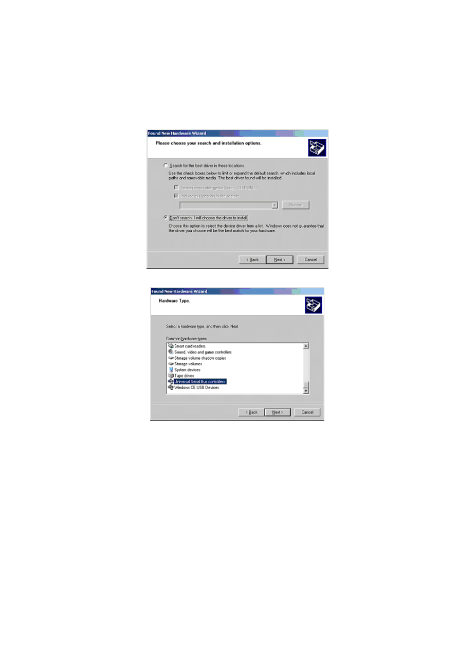
4.
Select
Don't search, I will choose the driver to install
, click
Next
.
5.
In the list of hardware types, select
Universal Serial Bus controllers
and click
Next
.
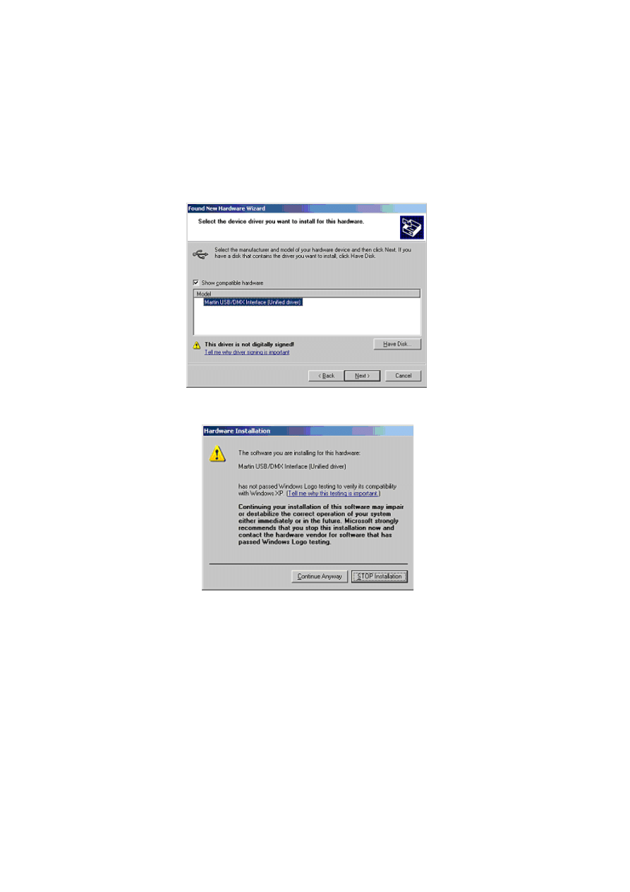
6.
Click
Have Disk
.
7.
Click
Browse
to locate the folder with the driver and then click
OK
.
2 0
8.
If a suitable driver is found in the folder, the Wizard will list the driver name and
location. Check this information to ensure that the correct driver has been found.
Click
Next
.
9.
A warning may appear, stating that this driver has not been digitally signed (checked
by Microsoft). Click
Continue Anyway
to continue.
2 1
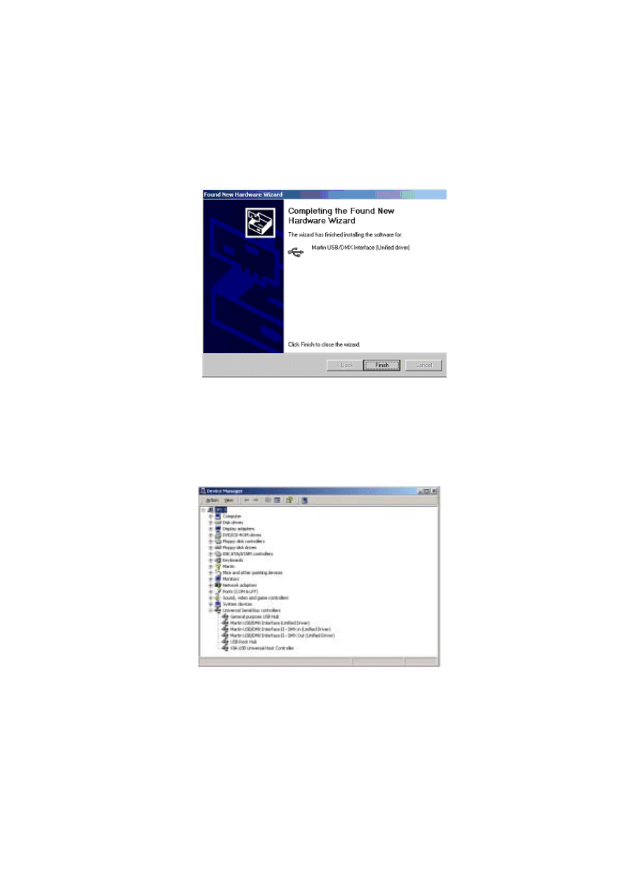
10.
Windows will now install the driver. Check the finishing dialog identifies the device
correctly.
11.
Click
Finish
and if additional LightJockey USB/DMX interfaces are present then
repeat this procedure from step 2 until a driver for each has been installed.
12.
To ensure that the drivers are properly installed and in working order open the
device manager by right-clicking
My Computer
, select properties from the popup
menu. Select the
Hardware
tab and then click
Device Manager
.
13.
Expand the
Universal Serial Bus Controllers
entry and check that the correct
driver is displayed (without an exclamation mark, as this indicates that there is a
problem.
To ensure that LightJockey routes DMX data to the correct interface when
operating with multiple LightJockey USB/DMX interfaces, always connect:

2 2
•
All USB/DMX interfaces to the USB port(s) on the PC before applying power to
the PC. This includes a first time setup and configuration.
•
Each USB/DMX interface to the same physical USB port on the PC.

2 3
Windows 95, Windows 98, or Windows ME
The LightJockey supports five types of hardware under Windows 95/98/ME:
•
LightJockey PCI card. See “Installing the LightJockey PCI card on a Windows
•
LightJockey 4064 8-bit ISA card. See “Installing the LightJockey 4064 ISA card on a
Windows 95/98/ME system” on page 25.
•
LightJockey parallel port interface. See “Installing the LightJockey ADP parallel port
interface on a Windows 95/98/ME system” on page 28.
•
LightJockey PCMCIA interface. See “Installing the LightJockey PCMCIA interface
on a Windows 95/98/ME system” on page 29.
•
LightJockey USB interface. See “Installing the LightJockey USB/DMX interface on a
Windows 95/98/ME system” on page 29.
Installing the LightJockey PCI card on a Windows 95/98/ME
system
The LightJockey PCI card comes in two flavors - the PCI 2048 channel version and the
PCI 512 channel version. The installation process is identical for both types.
Support for the LightJockey PCI cards was introduced in LightJockey version 2.1. Ensure
that you have this version, or later, before starting these procedures. The version is
printed on the CD. Updates can be downloaded from the Service pages at
http://www.martin.dk
The card can be damaged by static electricity. Release static electric charges before
handling the hardware by touching a grounded metal object, and always avoid touching
sensitive electronic components.
Installing the card
To install the LightJockey PCI card:
1.
Turn off the computer.
2.
Disconnect the power cord. Failure to unplug the cord could result in injury to you or
damage to the computer.
3.
Remove the computer cover.
4.
Find an available PCI expansion slot and remove its cover plate from the back of the
computer chassis.
5.
Holding the card by the bracket and corner, push the card's copper contacts into the
expansion slot. Ensure that the card is correctly seated in the PCI slot.
6.
Fasten the card to the chassis.
7.
Replace the cover and reconnect the power cord.
8.
Connect the DMX output cable(s) to the card. There:
•
Are 2 connectors on the PCI 2048 version: The top connector has DMX output

2 4
for DMX links 1 and 2; the bottom connector has DMX output for DMX links 3
and 4, or alternatively DMX output for DMX link 3 and input for DMX in.
•
Is 1 connector in the PCI 512 version, supporting both DMX input and output.
9.
Restart the computer. The LightJockey PCI card is Plug and Play compatible.
Windows will automatically detect the card once it has been installed and the
Found
New Hardware
wizard will start.
10.
Use the wizard to locate the
4064PCI.inf
file which is located in the
HardwareDrivers\PCI_ISA
folder on the LightJockey CD-ROM (or in the same
sub-folder of the
Martin LightJockey
folder, if you have already installed
LightJockey).
11.
Once the driver has been installed and Windows has started, right-click on
My
Computer
, and then click
Properties
to open the
System Properties
dialog box.
12.
Click
Hardware
.
13.
Click
Device Manager...
to open the
Device Manager
dialog box.
14.
Check that the device
Martin PCI4064: DMX PCI Card
appears under
Martin
devices
.
15.
Go to the next section and install the PCI/ISA driver.
Installing the PCI/ISA driver
Install the PCI/ISA driver:
1.
Using Windows Explorer, open the
HardwareDrivers\PCI_ISA
folder on the CD-
ROM, or if you have already installed LightJockey, in the same sub-folder of the
Martin LightJockey folder.
2.
Double-click the
Installer
application to start it. (If the driver has already been
installed then a message will appear indicting this).
2 5
3.
Click
Install Driver
.
4.
Click
Locate Card(s)
and the newly installed card should appear listed in the
window.
5.
Restart Windows.
6.
Go to “Software installation” on page 34.
Installing the LightJockey 4064 ISA card on a Windows
95/98/ME system
The LightJockey 4064 ISA card comes in two flavors - the 2048 DMX channel Club
version and the 512 channel DJ version. Note that no drivers are required to operate the
ISA card under Windows 95,98 or ME.
The card can be damaged by static electricity. Release static electric charges before
handling the hardware by touching a grounded metal object, and always avoid touching
sensitive electronic components.
Setting the DIP switch on the card
The card’s DIP-switch setting may need to be adjusted. To find out:
1.
From the Desktop, right-click
My Computer
.
2.
Select
Properties
→ Device Manager → Properties
.
2 6
3.
Select
Memory
to view a list similar to the one in the following illustration.
4.
If no device is allocated to the memory from 000D2000 to 000D2FFF, the card’s
default DIP-switch setting (pins 2 and 5 on) will work and you can proceed to
“Installing the card” on page 28.
2 7
Otherwise, select an unoccupied memory block with the help of the following table:
5.
Set the card’s DIP switch for the unoccupied memory block by moving the pins
indicated under “Pins On” to the ON position. Move all other pins to the off
position. Check that the correct DIP switches are ON, and that all other DIP
switches are OFF.
6.
Close the
Device Manager
window.
7.
You can now install the card in your computer. See “Installing the card” on page 28.
B l o c k
A d d r e s s
R a n g e
P i n s
O n
B l o c k
A d d r e s s
R a n g e
P i n s
O n
C SEGMENT
C0
000C0000
000C0FFF
None
D SEGMENT
D0
000D0000
000D0FFF
5
C1
000C1000
000C1FFF
1
D1
000D1000
000D1FFF
1, 5
C2
000C2000
000C2FFF
2
D2
000D2000
000D2FFF
2, 5
C3
000C3000
000C3FFF
1, 2
D3
000D3000
000D3FFF
1, 2, 5
C4
000C4000
000C4FFF
3
D4
000D4000
000D4FFF
3, 5
C5
000C5000
000C5FFF
1, 3
D5
000D5000
000D5FFF
1, 3, 5
C6
000C6000
000C6FFF
2, 3
D6
000D6000
000D6FFF
2, 3, 5
C7
000C7000
000C7FFF
1, 2, 3
D7
000D7000
000D7FFF
1, 2, 3, 5
C8
000C8000
000C8FFF
4
D8
000D8000
000D8FFF
4, 5
C9
000C9000
000C9FFF
1, 4
D9
000D9000
000D9FFF
1, 4, 5
CA
000CA000
000CAFFF
2, 4
DA
000DA000
000DAFFF
2, 4, 5
CB
000CB000
000CBFFF
1, 2, 4
DB
000DB000
000DBFFF
1, 2, 4, 5
CC
000CC000
000CCFFF
3, 4
DC
000DC000
000DCFFF
3, 4, 5
CD
000CD000
000CDFFF
1, 3, 4
DD
000DD000
000DDFFF
1, 3, 4, 5
CE
000CE000
000CEFFF
2, 3, 4
DE
000DE000
000DEFFF
2, 3, 4, 5
CF
000CF000
000CFFFF
1, 2, 3, 4
DF
000DF000
000DFFFF
1, 2, 3, 4, 5

2 8
Installing the card
1.
Turn off the computer.
2.
Disconnect the power cord. Failure to unplug the cord could result in injury to you or
damage to the computer.
3.
Remove the computer cover.
4.
Find an available ISA expansion slot and remove its cover plate from the back of the
computer chassis.
5.
Holding the card by the bracket and corner, push the card's copper contacts into the
expansion slot. Ensure that the card is correctly seated in the ISA slot.
6.
Fasten the card to the chassis.
7.
Replace the cover and reconnect the power cord.
8.
Connect the DMX output cable(s) to the card. There:
•
Are 2 connectors on the Club version: The top connector has DMX output for DMX
links 1 and 2; the bottom connector has DMX output for DMX links 3 and 4, or
alternatively DMX output for DMX link 3 and input for DMX in.
•
Is 1 connector in the DJ version, supporting both DMX input and output.
Note that once the card is installed it may not show up in the
Device Manager
. This can
occur because of a driver problem, but will not prevent the card from functioning
correctly. If this occurs, make a note of the memory address range that the card uses and
when installing new devices in the future, ensure that they do not use memory in this
range.
Installing the LightJockey ADP parallel port interface on a
Windows 95/98/ME system
The parallel port interface enables Windows 95/98 laptops and PCs without an ISA
expansion slot to send DMX through the parallel port. The interface provides 512 DMX
channels on one link.
1.
Disconnect the PC and remove the power cord to avoid risk of injury.
2.
Insert the ADP interface into the 25-pin parallel port and fasten it with the 2 screws.
Check that the interface is properly seated in the parallel port.
3.
If a keyboard or PS/2 mouse port is not in use, connect the male PS/2 connector to
the port. (Use a PS/2 to DIN adapter if required.) If there are no free ports,
disconnect one and connect the male PS/2 connector from the interface. Then
connect the keyboard or mouse to the female PS/2 connector.
4.
Go to “Software installation” on page 34.
Note that:
•
As the parallel port does not deliver sufficient electrical current for DMX
transmission, the interface takes power from a keyboard or PS/2 mouse port.

2 9
•
If the status LED of the interface is not lit, there is no power from the keyboard or
PS/2 mouse port. Disconnect the cables and repeat the installation procedure.
•
On certain PCs, especially laptops, it may be necessary to enable both the parallel port
and the power supplying keyboard or PS/2 mouse port in order to use the DMX ADP.
Please consult your PC documentation for details if the adapter fails to work.
•
Laptop users should disable power-saving functionality as this can cause the
DMXADP interface to malfunction.
Installing the LightJockey PCMCIA interface on a Windows
95/98/ME system
The PCMCIA interface provides two 512 channel DMX links. One link may be used as a
DMX input. For installation, please refer to the PCMCIA Adapter QuickStart User's
Guide. Once you have installed the PCMCIA interface go to “Software installation” on
page 34.
Installing the LightJockey USB/DMX interface on a Windows
95/98/ME system
There are three types of LightJockey USB/DMX interface:
1.
Original LightJockey USB/DMX
2.
LightJockey USB/DMX II-in
3.
LightJockey USB/DMX II-out
Up to four LightJockey USB/DMX out (original model or version II) and one
LightJockey USB/DMX II in interfaces can be connected to a PC. LightJockey version
2.5, or higher, is required.
Note regarding the Location of the USB driver
The guidelines in this section refer to the 'location of the USB driver' in several places.
The exact location of the driver files will depend on if what the installation is. If:
1.
The driver has been downloaded as a separate update, the driver files will be located
where they were unzipped to on the hard drive.
2.
LightJockey is installed/updated from a CD the driver are located on the CD in
\HardwareDrivers\USB2\
3.
The driver is updated from a downloaded release of LightJockey, run LightJockey
once to unpack compressed files. The driver files are now located in <LightJockey
Installation>\HardwareDrivers\USB2\
Before the LightJockey USB/DMX interface can be used with LightJockey, you must
install the correct USB device driver. Note that each of the three types of LightJockey
USB/DMX interface has their own driver:
•
Martin USB/DMX Interface (Unified Driver)
3 0
•
Martin USB/DMX Interface II - DMX Out (Unified Driver)
•
Martin USB/DMX Interface II - DMX In (Unified Driver)
1.
Turn on the PC with the interfaces attached.
2.
Once Windows has detected an interface, the
Found New Hardware Wizard
will
appear, prompting for a driver for a EZ-USB device.
3.
Click
Next
.
4.
Select
Search for best driver for your device
, and then click
Next
.
3 1
5.
Select
Specify a location
and click
Browse
to locate the folder containing the
driver. Then click
Next
.
6.
If a suitable driver is found in the folder, the Wizard will list the driver name and
location. Check this information to ensure that the correct driver has been found.
Click
Next
.
7.
Wait while Windows re-builds the driver database, and then click
Finish
.
8.
If additional LightJockey USB/DMX interfaces are present then repeat this proce-
dure from step 2 until a driver for each has been installed.
3 2
9.
To ensure that the drivers are properly installed and in working order open the device
manager by right-clicking
My Computer
, select properties from the popup menu,
then select the
Device Manager
tab.
10.
Expand the
Universal Serial Bus Controllers
entry and check that the correct
driver is displayed (without an exclamation mark, as this indicates that there is a
problem.
To ensure that LightJockey routes DMX data to the correct interface when
operating with multiple LightJockey USB/DMX interfaces, always connect:
•
All USB/DMX interfaces to the USB port(s) on the PC before applying power to
the PC. This includes a first time setup and configuration.
•
Each USB/DMX interface to the same physical USB port on the PC.
3 3
Notes on removing the PCI/ISA driver
You can remove this driver using the
Installer
application but it is a generic Windows
driver that might be used to drive other types of hardware in the PC. Removing the
driver may cause other types of hardware to stop functioning. Do not remove the
driver unless you are certain that it is not needed for other types of hardware.
To remove the driver:
1.
Using Windows Explorer, open the
HardwareDrivers\ISA\W2K
folder on the
CD-ROM, or if you have already installed LightJockey, in the same sub-folder of the
Martin LightJockey folder.
2.
Double-click the
Installer
application to start it.
3.
Click
Remove
Current Driver
.
4.
Click
Close
.
3 4
Software installation
The LightJockey CD uses the Windows auto-start feature to launch the setup program
when the CD-ROM is inserted. If this feature is disabled and installation does not start
automatically double-click on the Launch.Exe program located in the root of the CD-
ROM.
If you have already installed LightJockey, then go to “Hardware configuration” on
page 38.
To install on a PC without CD-ROM drive:
1.
Copy the contents of the DiskX directories to individual 1.44 MB floppy disks.
2.
Insert the floppy disk with the Disk1 contents into the PC.
3.
Run setup.exe.
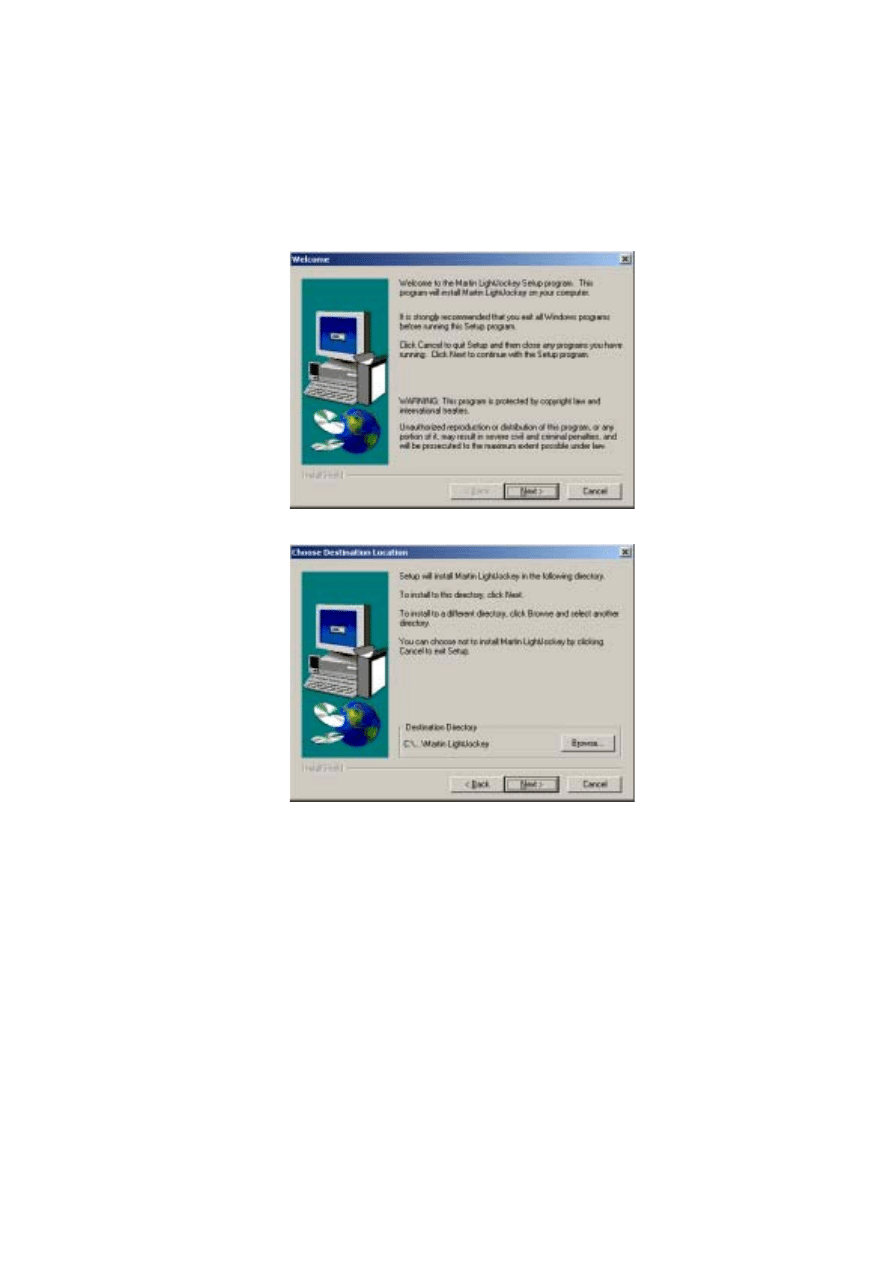
Follow the installation procedure:
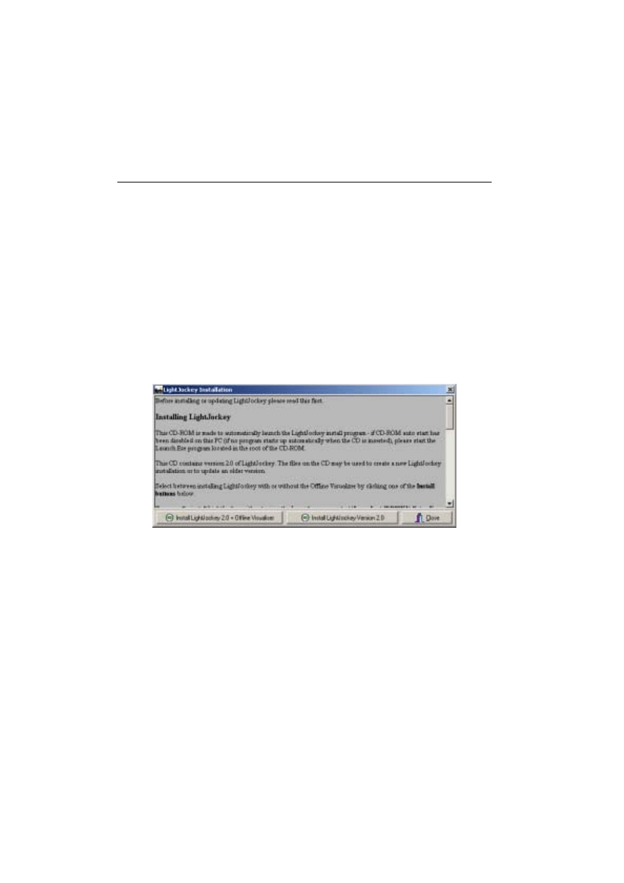
1.
Once the installation program starts the following window will appear
2.
Click either Install LightJockey x.x + Offline Visualizer or Install LightJockey
x.x to install with, or without, the Offline Visualizer (OV). The OV is a scaled down
version of the offline module from Martin Show Designer (MSD) that has been inte-
grated into LightJockey. The OV offers real-time animation of fixtures in a black-
box environment. For more information refer to the LightJockey online help.
3 5
3.
The following window will appear.
4.
Click
Next
.
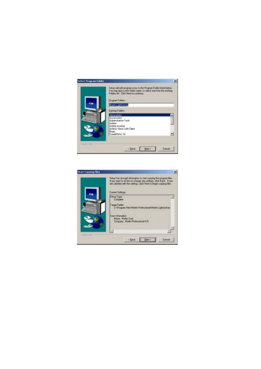
3 6
5.
If the
Destination Directory
is appropriate click
Next
. Otherwise specify a another
one using the
Browse
button, selecting the appropriate directory, and pressing
Next
.
6.
Accept the default program folder, or select another from the list.
7.
Click
Next
.
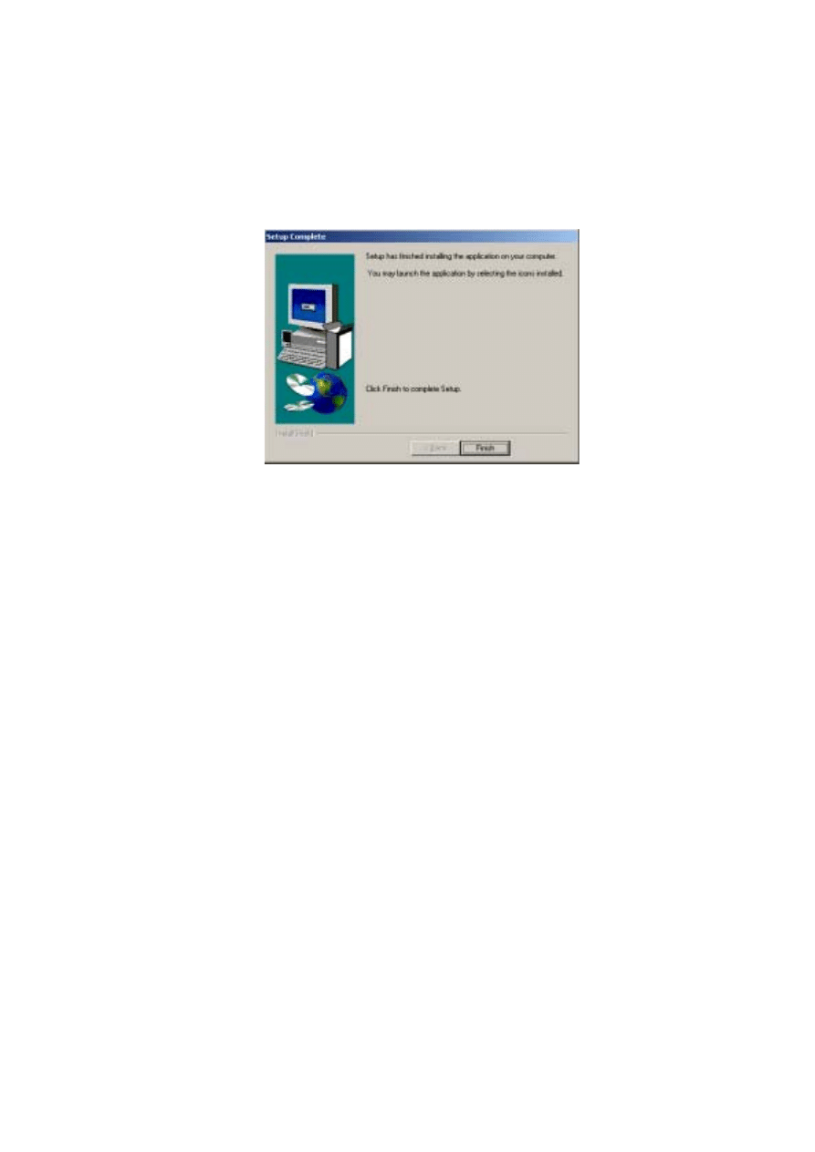
3 7
8.
Review the settings and click
Next
to continue.
9.
Click
Finish
.
10.
Start LightJockey by clicking on the LightJockey icon located in the programs
folder in the Windows start menu.
11.
Follow the steps under “Hardware configuration” on page 38.
3 8
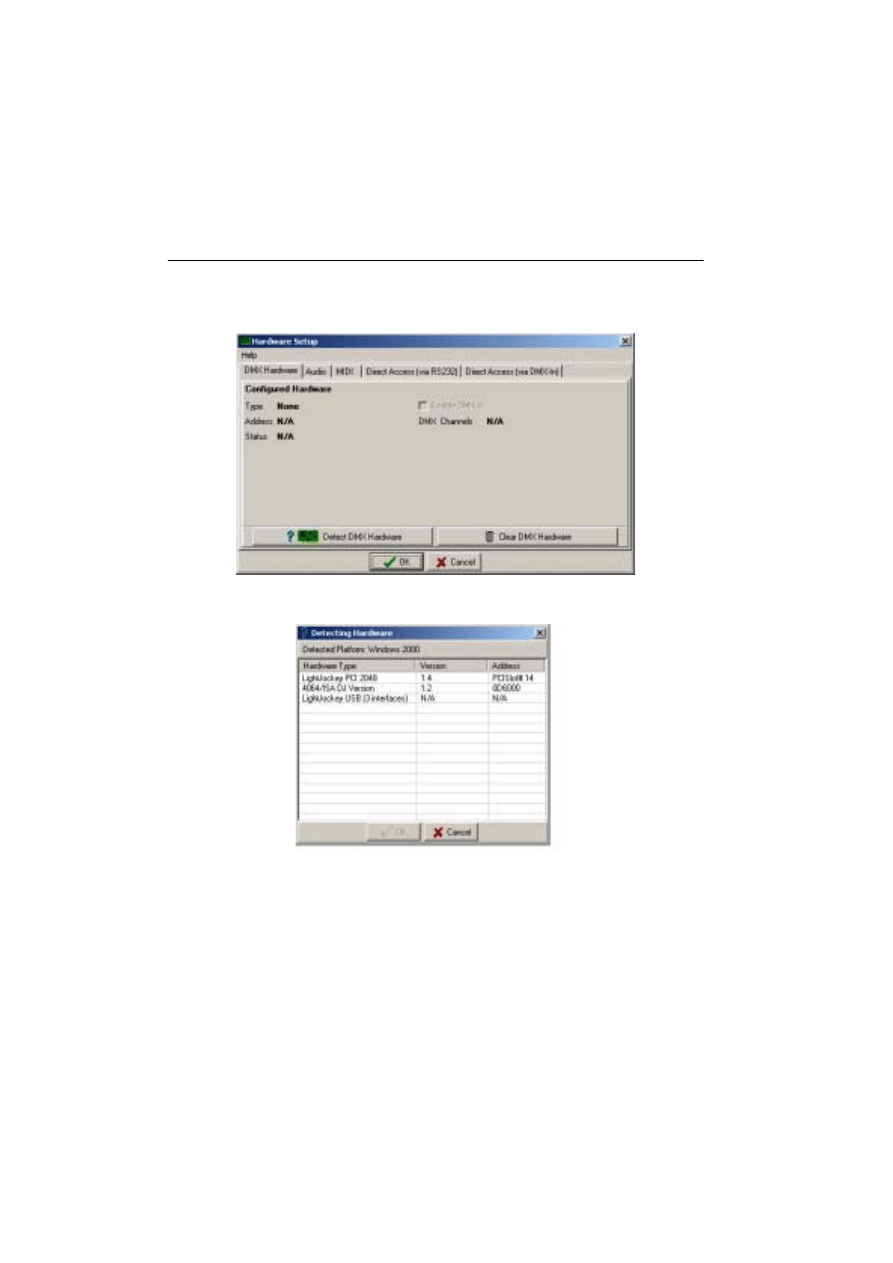
Hardware configuration
Start LightJockey, and from the LightJockey main window:
1.
Click
Setup
→Hardware
.
2.
Click
Detect hardware
. LightJockey searches for available hardware and lists all
hardware found. The search may take up to 20 seconds.
3.
Select the appropriate hardware by clicking on it in the list.
4.
Click
OK
to return to the
Hardware Setup
window. Note that some interfaces
support settings that can be configured from the tabs in this window, such as
selecting the DMX refresh rate. Normally the highest DMX rate should be selected
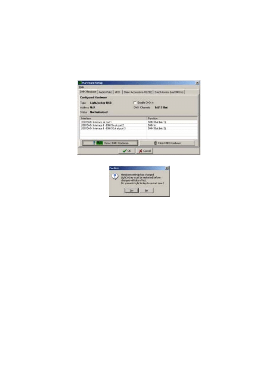
3 9
as lowering the DMX rate may cause some fixtures to respond less smoothly during
high fade times.
5.
Restart LightJockey when prompted.
6.
Follow the steps under “Connecting the serial data link” on page 40.
4 0
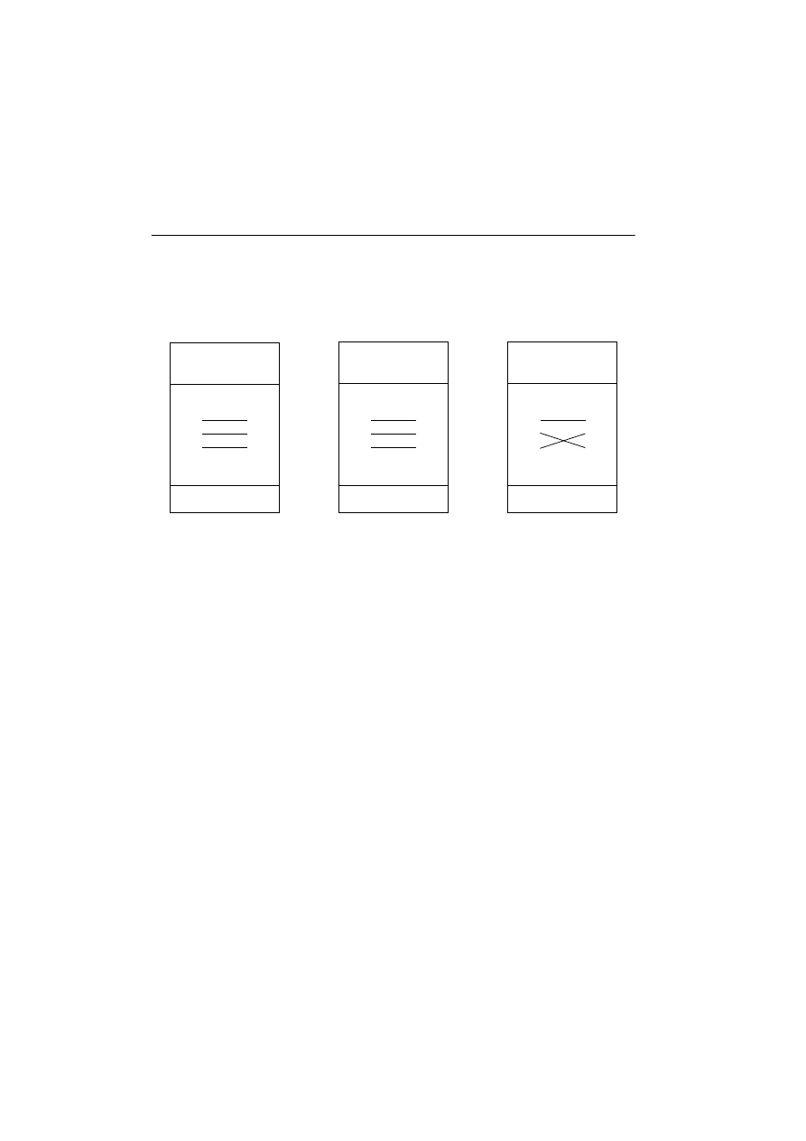
Connecting the serial data link
The pin-out of the 3-pin DMX connectors is compatible with the DMX-512
standard, i.e., pin 1 to shield, pin 2 to cold (-) and pin 3 to hot (+). As some devices have
5-pin connectors, or 3-pin connectors with reversed polarity on pins 2 and 3, the
following adaptor cables may be required.
Always remember to terminate the end of a data link with a 120.ohm terminating plug.
Interface XLR cable connections
LightJockey PCI 512 and 4064 ISA DJ cards
These cards are supplied with a SUB-D to XLR cable. DMX out is through the female
XLR and DMX in is through the male XLR.
LightJockey PCI 2048 and 4064 ISA Club cards
These cards are supplied with three SUB-D to XLR cables. The
•
D-SUB to 2 x female XLR should be used in the top SUB-D connector for 2 x DMX
out
•
Second 2 x female XLR should be used in the lower SUB-D socket if the card is
configured with 4 x DMX out.
•
Male plus female XLR cable if the card is configured to receive DMX in. Male plus
female XLR cable should be used in the lower D-SUB socket if the card is
configured to receive DMX in.
DMX out is through the female XLR and DMX in is through the male XLR.
Phase-Reversing
Adaptor
Male
Female
1
2
3
1
2
3
3-pin to 3-pin
P/N 11820006
Adaptor
Male
Female
1
2
3
4
5
1
2
3
5-pin to 3-pin
P/N 11820005
Adaptor
Male
Female
1
2
3
1
2
3
4
5
3-pin to 5-pin
P/N 11820004

4 1
DMXADP interface
Connect a 3-pin XLR to the female XLR output of the interface.
PCMCIA interface
When using:
•
1 PCMCIA interface, outputs for links 1 and 2 are located as displayed on the
breakout box.
•
2 PCMCIA interfaces, outputs for links 3 and 4 are located on the breakout box
connected to the second PCMCIA card.
USB interface
Connect the data link to the 3-pin XLR on the USB interface.
Connecting to fixtures
1.
Connect the controller’s output to the first fixture’s data input. For a DMX fixture
with 5-pin input, use a cable with 3-pin male and 5-pin female XLR connectors. For
a DMX fixture with 3-pin input, use a cable with 3-pin male and female connectors.
For a Martin RS-485 protocol fixture, use a phase reversing cable with 3-pin male
and female connectors.
2.
To connect additional fixtures, connect the output of the fixture closest to the
controller to the input of the next fixture. When connecting a DMX fixture to a
Martin fixture with pin 3 cold (-), use a 3-pin phase-reversing adaptor.
3.
Terminate the link. Insert a male 120 ohm XLR termination plug in the output of the
last fixture on the link. The termination plug, which is simply a male XLR connector
with a 120 ohm, 0.25 watt resistor soldered between pins 2 and 3, “soaks up” the
control signal so it does not reflect back down the link and cause interference.
Tips for building a trouble-free serial link
•
Use shielded twisted-pair cable designed for RS-485 devices. Standard microphone
cable is not designed for use in serial links and often causes unpredictable
performance.
•
Never use a “Y” connector to split the link. To split the serial link into branches use a
splitter such as the Martin 4-Channel Opto-Isolated RS-485 Splitter/Amplifier. If a
splitter/amplifier is used, terminate each branch of the link.
•
Do not overload the link. Up to 32 devices may be connected on a serial link. If a
splitter/amplifier is used, up to 32 devices may be connected on each branch.

4 2
Introduction to programming
This part of the guide explains the controller’s basic features and philosophy to help you
start programming. Information about new and advanced features is located in the on-line
help system.
Tip: As you go through this introduction, pay attention to how the Off/Snap/Fade control
effects sequence execution.
If you have programmed with the Martin 3032, you will find the LightJockey similar in
many ways. Fade times and the Off/Snap/Fade control, however, will be new to you.
This guide assumes that you are familiar with Windows. As you experiment with the
controls, be aware that clicking with the left and right mouse buttons often does different
things.
You do not need to have actually have any fixtures connected to perform the exercises,
although it is recommended. The examples are based around two Mac 600 fixtures, but in
theory you should be able to replicate the same cases with most other Martin MAC-series
fixtures.
4 3
Identifying the controls
This section describes the LightJockey controls. Note that screens and buttons may differ
from those shown here depending on software version that is being used.
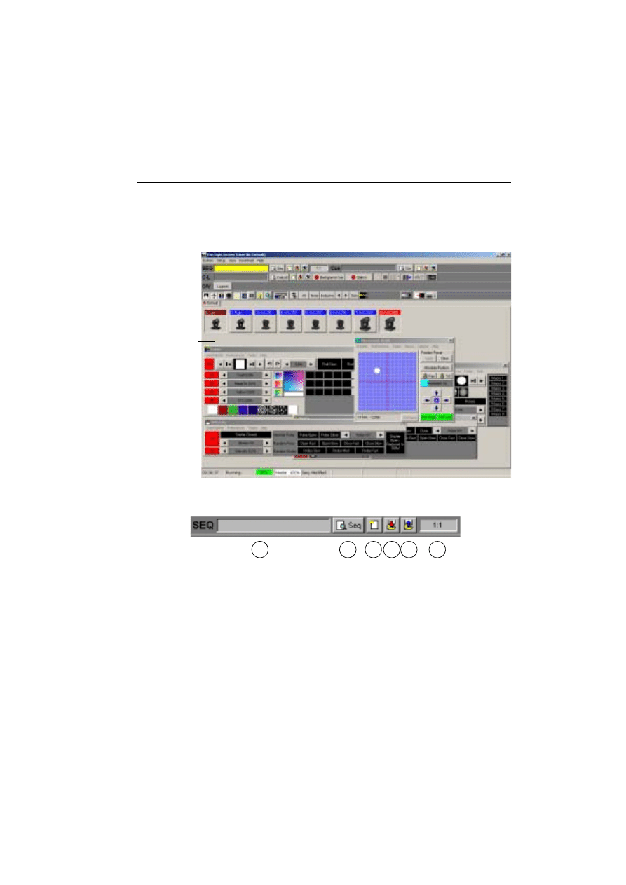
Main screen
Sequence toolbar
1.
Sequence name field
2.
View Sequence Control button
3.
New/Clear Sequence button
4.
Save Sequence button
5.
List of Sequences button
6.
Scene number field (current scene : total scenes)
Main menu
Seq & Cue Toolbars
Status bar
Page tabs
Fixture icons
Control windows
Cue List Toolbar
Fixture Toolbar
Offline Visualizer
LightJockey Desktop
1
2
3 4 5
6
4 4
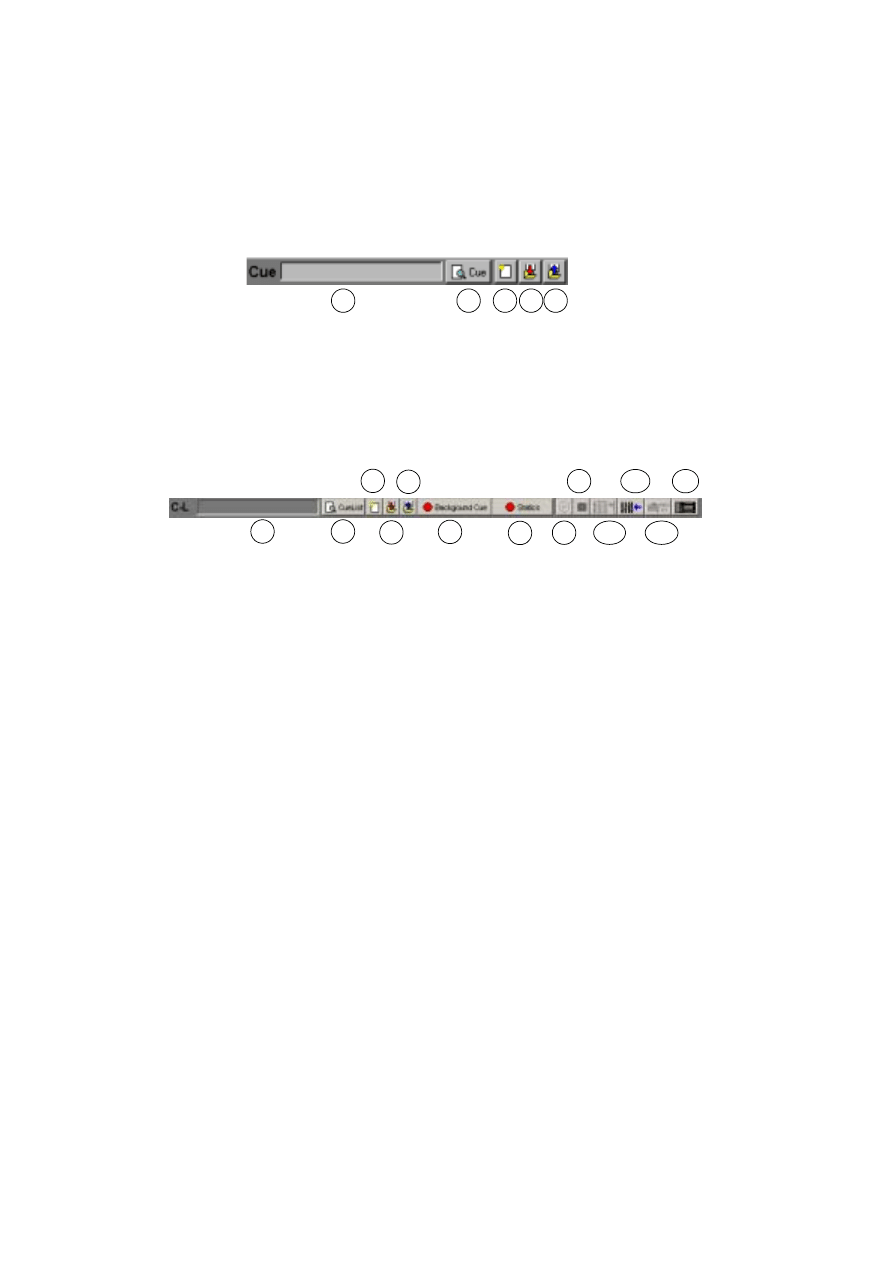
Cue toolbar
1.
Cue name field
2.
View Cue Control button
3.
New/Clear Cue button
4.
Save Cue button
5.
List of Cues button
Cue List toolbar
1.
Current Cue List name field
2.
Toggle Cue List control button
3.
New/Clear Cue List button
4.
Save Cue List button
5.
List of Cue Lists button
6.
Background Cue Control button
7.
Static Control button
8.
CD control button
9.
MCX (Direct Access) button
10.
2518 Direct Access button
11.
DMX In button
12.
MIDI In button
13.
2532 Direct Access button
1
2
3 4 5
1
2
3
4
5
6
7
8
9
10
11
12
13

4 5
Fixture toolbar
1.
Intensity button
2.
Movement button
3.
Color button
4.
Gobo button
5.
Beam button
6.
Effect button
7.
Levels/Extended Controls button
8.
Lamp button
9.
Reset button
10.
Hide/Show Fixture Controls button
11.
Fixture Groups button
12.
Select All Fixtures button
13.
Deselect All Fixtures button
14.
Fixture Selection Mode button (
Inclusive
or
Exclusive
)
15.
Previous Fixture button
16.
Next Fixture button
17.
Fixture Solo button
18.
Followspot button
19.
Smoke Control button
20.
Blackout button
21.
Master Intensity button
21
20
19
18
17
16
15
14
13
1
2
3
4
5
6
7
8
9
10
11
12

4 6
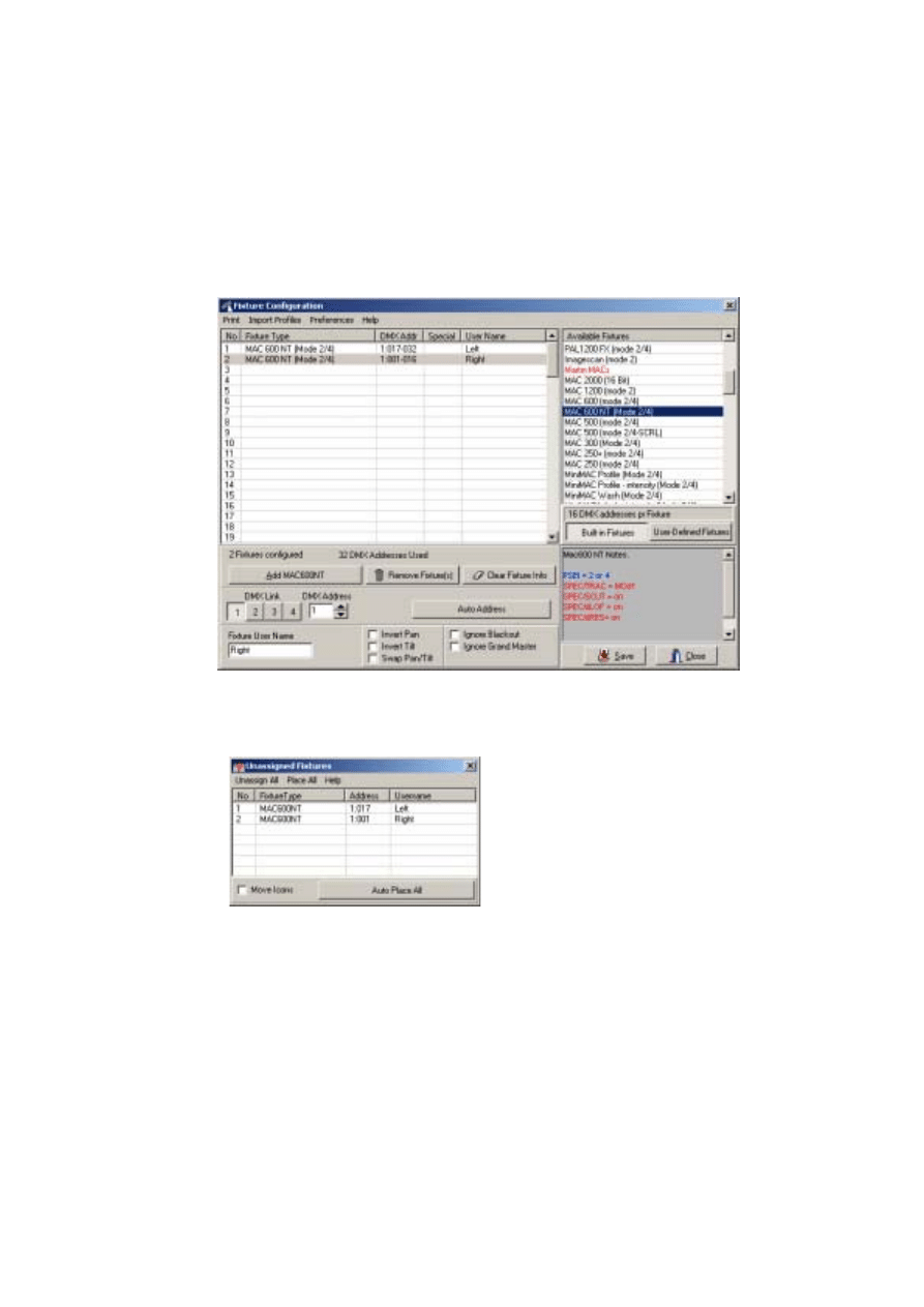
Configuring fixtures
The first step after setting up the hardware is to select and address your lighting fixtures in
the Fixture Configuration window, which you open by choosing
Setup
→Fixture
Configuration
from the main menu.
Example: Configure 2 MAC 600s
1.
Click
Setup
→Fixture
Configuration
from the main menu.
2.
Click
MAC 600 (mode 2/4)
from
Available Fixture
.
3.
Drag and drop it onto line
No
1
.
4.
Add another fixture of the same type to line
No 2
.
5.
For each of the two fixtures in the list: Click
Auto Address
, click
Find Addresses
,
and then click
OK
. Addresses can also be set manually in the
DMX Address
field at
the bottom of the screen. Regardless of the method that you use, the DMX addresses
and modes (that affect the number of DMX channels that are used) set in the actual
fixtures must match those in the LightJockey fixture configuration in order for
communication between the LightJockey and the fixture to function. Refer to the
fixture user manual for guidance.
4 7
6.
Click line number
1
to select the first fixture in the list. Type
Left
in
Fixture User
Name
(located at the lower-left of the window). Repeat this process for the second
fixture in the list, assigning it the name,
Right
.
7.
Click
Save
. If you are prompted to
Clear data for new fixtures?
, click
Yes
and
when the subsequent confirmation window appears, click
OK
.
8.
Click
Close
to return to the LightJockey desktop where the
Unassigned Fixtures
dialog box will appear.
4 8
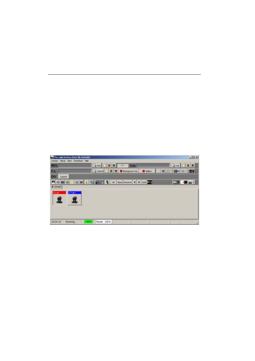
Configuring the desktop
Lighting fixtures are represented by icons on screen. To create and place icons, you drag
fixtures from the Unassigned Fixtures list to the desktop. Icons may be organized any way
you like on multiple pages or “tabs.”
Menus for arranging the desktop and icons, etc., pop up if you right-click on the desktop
and icons.
Example: Place 2 MAC 600s on desktop
1.
The list of unassigned fixtures is displayed on the desktop automatically. (If at any
point you close it, re-open the list by clicking
View
→Unassigned Fixtures
.
2.
Drag the MAC 600s from the list and drop them on to the desktop.
3.
Right-click the desktop.
4.
Click
Icons
→Auto Arrange...
.
5.
Click
OK
.
4 9
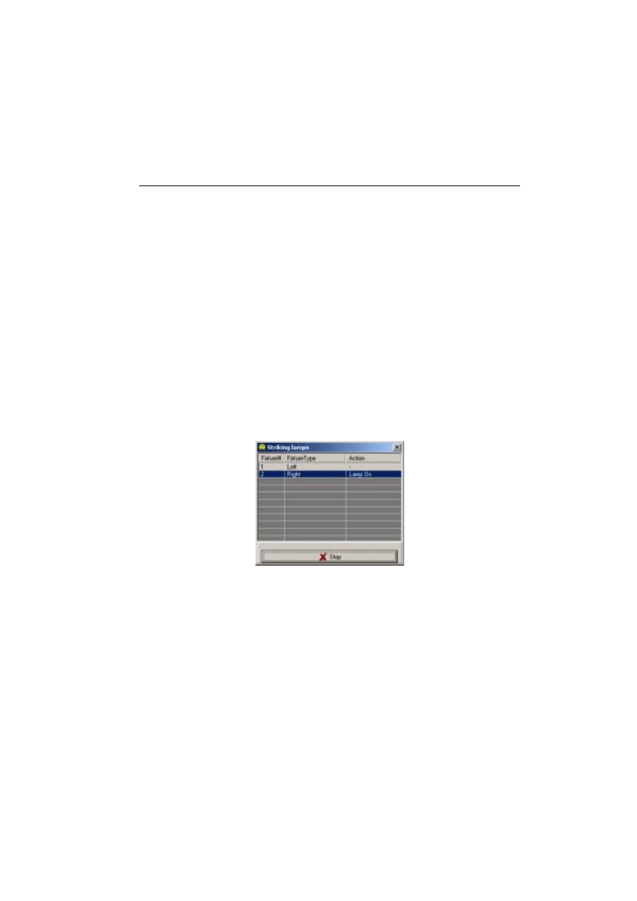
Striking lamps
Most Martin fixtures with discharge lamps, also known as arc lamps, must be struck
(turned on) from the controller. There are three ways to do this:
1.
Use the LightJockey’s automatic lamp-strike feature. This is recommended and is
described in the next example.
2.
Program a “lamp on” cue. This is not recommended because Martin fixtures use the
same DMX channel for lamp and shutter control. The lamp-on command will be
overridden by any higher-priority sequence with a shutter command. If you choose
to program a “lamp on” cue, turn on the lamps one at a time with 3 - 5 second inter-
vals to avoid excessive voltage drop and current draw.
3.
Strike a lamp manually by selecting it, clicking the Lamp button on the fixture tool-
bar, and then clicking
Power On
in the
Lamp Control
dialog box. Depending on the
fixture, this dialog box may also be used to turn off the lamp.
Example: Strike MAC 600s
1.
Perform the steps in the previous examples to configure 2 MAC 600s and place them
on the LightJockey desktop.
2.
Click
System
→Auto Strike Lamps
from the main menu.
3.
Click
Stop
once the LightJockey has been through the cycle once or twice and the
lamps have struck.
5 0
Programming cues
Cue building blocks
A light show is typically divided into cues that you program and then play back from the
list of available cues. The LightJockey also supports cue playback from the Martin 2532
Direct Access Controller, which is available as an accessory.
A cue points to up to 12 sequences that all run together at the same time, i.e., in parallel.
A sequence is made up of scenes. Scenes run one after the other, i.e., in sequence, and can
have different lengths (scene times).
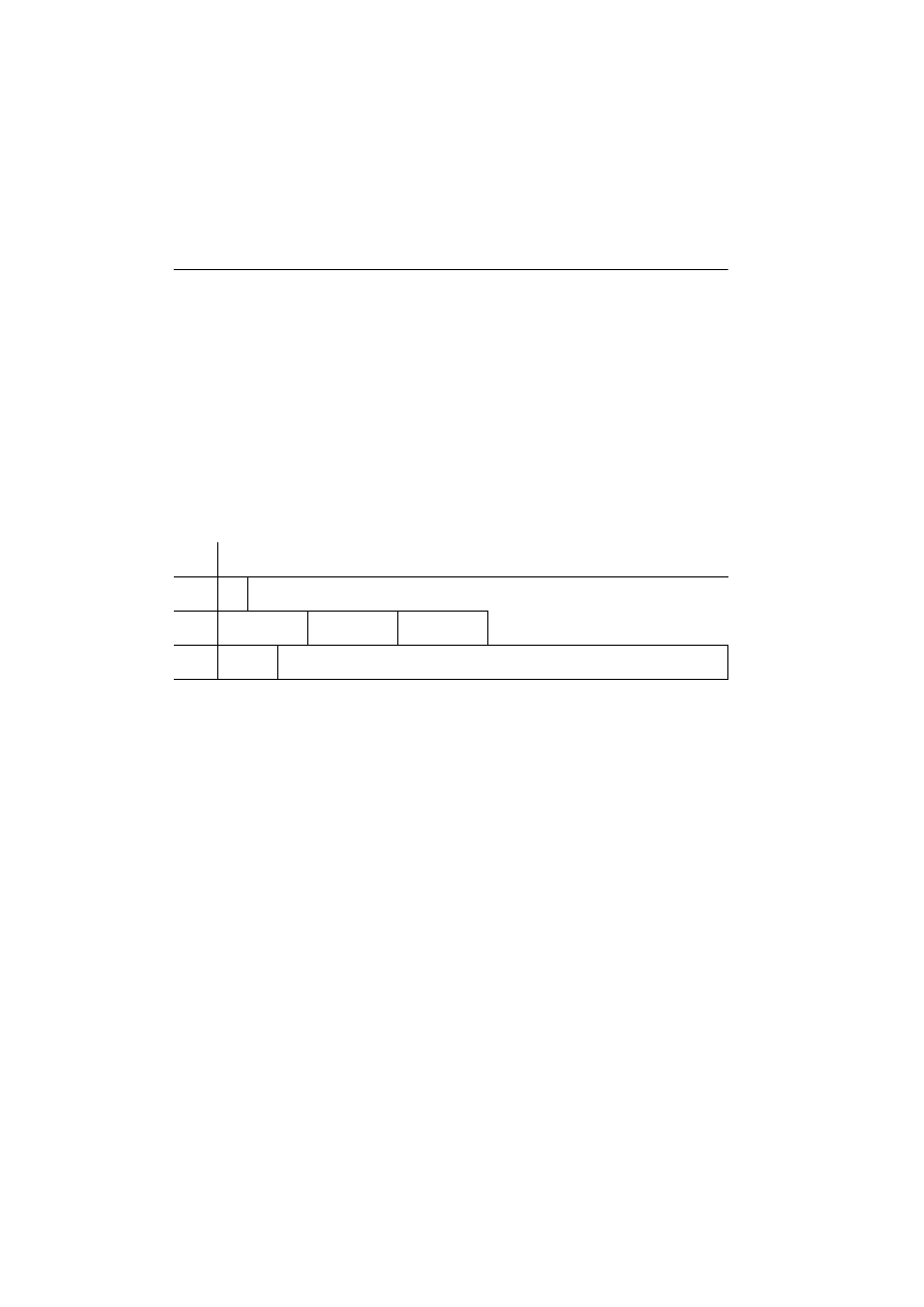
Later on you will program a cue with 3 sequences. The sequences have 1, 3, and 2 scenes,
respectively, with scene times as shown below. With the default loop settings, once a
sequence finishes, it loops back to the start and repeats for as long as you play the cue.
Bottom to top cue execution
It is essential that you understand how sequences are executed within a cue. Picture it as if
the LightJockey takes effects one at a time and looks for instructions at the bottom of the
cue. If the effect’s Off/Snap/Fade control is set to Snap or Fade, the controller executes
the instructions in the sequence and then moves to the next effect. If the effect’s control is
Off, it looks for instructions in the next higher sequence. The LightJockey continues up
the cue until it finds a Snap or Fade command.
If an effect is programmed in two sequences at the same time, the controller executes the
instruction closer to the bottom. If an effect does not behave as predicted it is probably
being controlled by a sequence lower in the cue.
In the example cue that follows, you open the shutter in the “20% dimmer” sequence - the
top sequence - and close it in scene 1 of the “Pan” sequence - the bottom sequence.
Sequence 3 has priority so the shutter closes during scene 1 and opens again in scene 2,
where the shutter control is Off. If you move “20% dimmer” below “Pan,” however, “20%
dimmer” has priority and the shutter stays open all the time.
Seq.
Scene action, number and time
1
*
1:1
*Open shutter. Open dimmer 20% (1 s)
2
C in, Y out
1:3 (3 s)
M in, C out
2:3 (3 s)
Y in, M out
3:3 (3 s)
3
Fast pan
1:2 (2 s)
Slow pan
2:2 (15 s)

5 1
Outline of programming steps
The basic steps for programming a cue are outlined below and explained in more detail in
the following sections.
I.
Create new cue.
II.
Program up to 12 sequences.
A.
Create new sequence.
B.
Program up to 999 scenes.
1.
Add scene. (Scene 1 is added automatically.)
2.
Program fixtures. Repeat as necessary.
a)
Select fixtures.
b)
Set desired effects.
c)
Set effects to snap or fade.
3.
Set fade and scene time.
C.
Save sequence.
D.
Add sequence to cue.
III.
Save cue.
Creating new cues
To program a cue you can either create a new one or load an existing one onto the desktop
using Windows techniques such as dragging and dropping. The cue on the desktop is
called the current cue.
Click the New/Clear Cue button on the
Cue
toolbar to create a new cue and clear the
current one. A gray
Cue
field indicates a new (empty) cue. It turns yellow when a
sequence has been added to the current cue.
The action of the current cue is dynamically represented in the control windows. The
pan/tilt cursor, for instance, moves back and forth to show a pan movement. This allows
you to see the effects of your programming without actual fixtures.
Creating and editing sequences
Just like cues, you program sequences by creating new ones or loading existing ones onto
the desktop. The sequence on the desktop is known as the current sequence.
To create a new sequence and clear the current one, click the New/Clear Sequence button
on the Sequence toolbar . The Sequence name field changes from yellow to gray to
indicate a new sequence; it turns yellow as soon as an instruction is programmed.

5 2
To edit an existing sequence, drag it from the List of Sequences to the desktop. Save
changes by clicking “Save Sequence” instead of “Save as New Sequence” in the save
dialog.
The action of the current sequence is displayed differently from the action of the current
cue. The controls for effects programmed in the current sequence do not move. This is to
make programming easier. The pan/tilt cursor, to take the previous example, stops moving
when you load the movement sequence onto the desktop. To “see” the sequence run, add
it to the current cue and clear it from the desktop.
Selecting fixtures
Fixtures must be selected before they can be programmed. The icon caption field is light
or dark red when a fixture is selected and blue when it is not selected. Click on fixture
icons to select and deselect them.
If you want to program a group of identical fixtures, say 2 MAC 600s, to do exactly the
same thing, you can select and program them together. When you want to program
fixtures to do different things, you must select and program them individually. (The
effects generator is a little different.) Of course you can program some effects together
and some effects individually.
Usually, you will program fixtures of different types separately, but some effects, such as
pan and tilt, may be programmed at the same time.
Programming effects
You control and program effects using slide bars, palettes, buttons, etc., in the fixture
control dialog boxes, which graphically represent each effect.
Control dialog boxes are opened and closed using the buttons on the Fixture toolbar.
There is an individual button for each control window as well as a master “Show Fixture
Controls” button that opens and closes all the commonly used control windows. Once
open, the windows may be dragged anywhere on screen.
Setting the Off/Snap/Fade control
Most controls have an
Off/Snap
/
Fade
button. Some controls, such as Lamp Control, have
Off
and
Snap
only. In the default setting, the button is red and
Off.
One click makes it a
yellow
Snap
button. Two clicks makes it a green
Fade
button.
Leave the button on Off (the default) unless you are programming a command. When an
effect’s
Off/Snap
/
Fade
button is Off, the control sends no instructions, allowing a lower-
priority sequence to control the effect.
Click the
Off/Snap
/
Fade
button to
Snap
to move the effect at maximum speed.
5 3
Click the
Off/Snap
/
Fade
button to
Fade
to fade the effect in or out using the fade time.
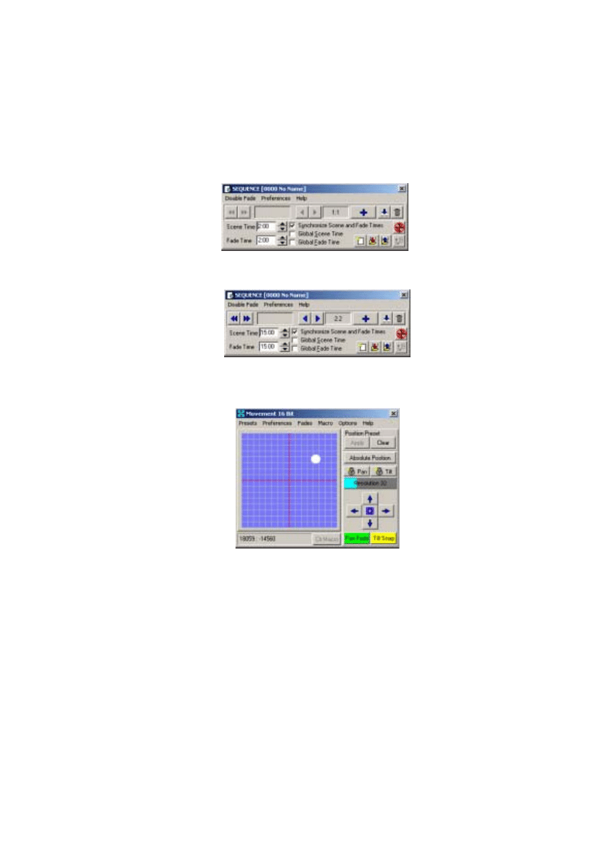
Setting scene and fade times
A scene lasts for a period of time known as the scene time. Fade time is the period of time
over which an effect moves if its
Off/Snap
/
Fade
control is set to
Fade
. (If the control is
set to
Snap
, the effect changes “instantly” at maximum speed.)
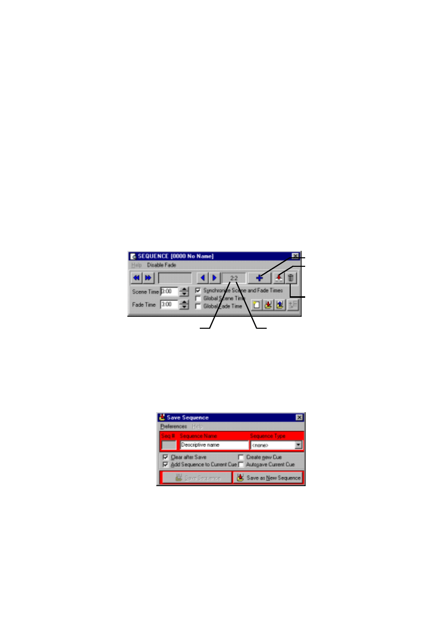
Scene and fade times are entered in the Sequence Control dialog box, which is shown
below.
Adding, inserting, and deleting scenes
A sequence can have anywhere from 1 to 999 scenes. Scenes are added, inserted, or
deleted by clicking buttons in the
Sequence Control
dialog.
Saving sequences
Sequences are named and saved using the
Save Sequence
dialog box. The dialog box
also has several check boxes that can be selected to speed up programming.
Click
Save Sequence
to save changes to an existing sequence or
Save as New
Sequence
to create a new sequence from the current sequence.
Add Scene
Insert Scene
Delete Scene
Total Scenes
Current Scene
5 4
Adding sequences to a cue
Windows techniques such as drag and drop can be used to add, delete, and rearrange
items in LightJockey lists. One way to add a sequence to a cue is to open the list of
available sequences (click List of Sequences on the Sequence toolbar), open the Cue
control window (click View Cue Control on the Cue toolbar), and drag the sequence to
the desired position in the cue. See also “Step 2: Add sequence to cue” on page 56.
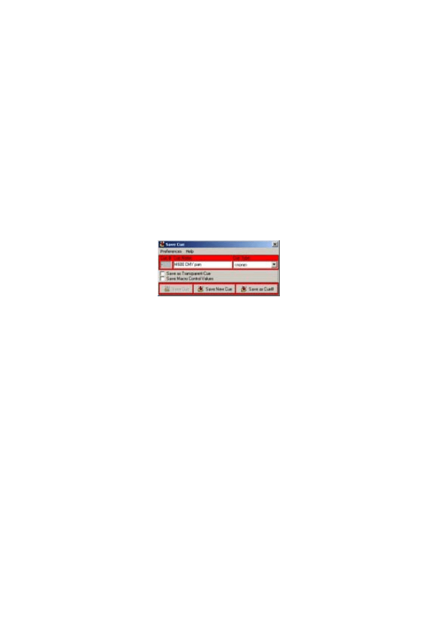
Saving cues
Cues are named and saved using the
Save Cue
dialog box. Click the Save Cue button on
the Cue toolbar, or on the
Cue [Cue-Number Cue-Name]
dialog box, to open the
Save
Cue
dialog box. Click
Save Cue
to save changes to an existing cue or
Save New Cue
to
create a new cue.
Example: Programming a cue
This example demonstrates the steps, concepts, and displays involved in programming. It
is designed to be programmed “blind” without fixtures attached.
The screen shots show how your screen should look if you follow the steps correctly.
Note, though, that the color palette is hidden in the Colors control window and that Show
Special is disabled in the Intensity Control window. These options are selected in the
windows’ Preferences menu.
Step 1: Program shutter/dimmer sequence
In this step you program a sequence to open the shutters and set the dimmers to 20%.
1.
Configure 2 MAC 600s and place them on the desktop if you have not done so.
2.
Locate the
Cue
field on the Cue toolbar. Be careful not to confuse the Cue toolbar
(
Cue
) with the Cue list toolbar (
C-L
).
3.
If the field is yellow, click the New/Clear Cue button. A new (empty) cue is indicated
by a gray
Cue
field.
4.
Locate the Sequence toolbar and click the New/Clear Sequence button if the
Seq
field is yellow.
5.
Click both MAC 600s to select them. The fixture icon caption is blue when the fixture
is not selected and light or dark red when it is selected.
5 5
6.
Click the Show Fixture Controls button on the Fixture toolbar.
7.
Arrange the control windows by dragging them on the LightJockey desktop.
Since you will not be using beam control in this example, close the Beam dialog box
to make more room on the LightJockey desktop. Individual dialog boxes controls
can be opened and closed as needed by clicking buttons on the Fixture toolbar.
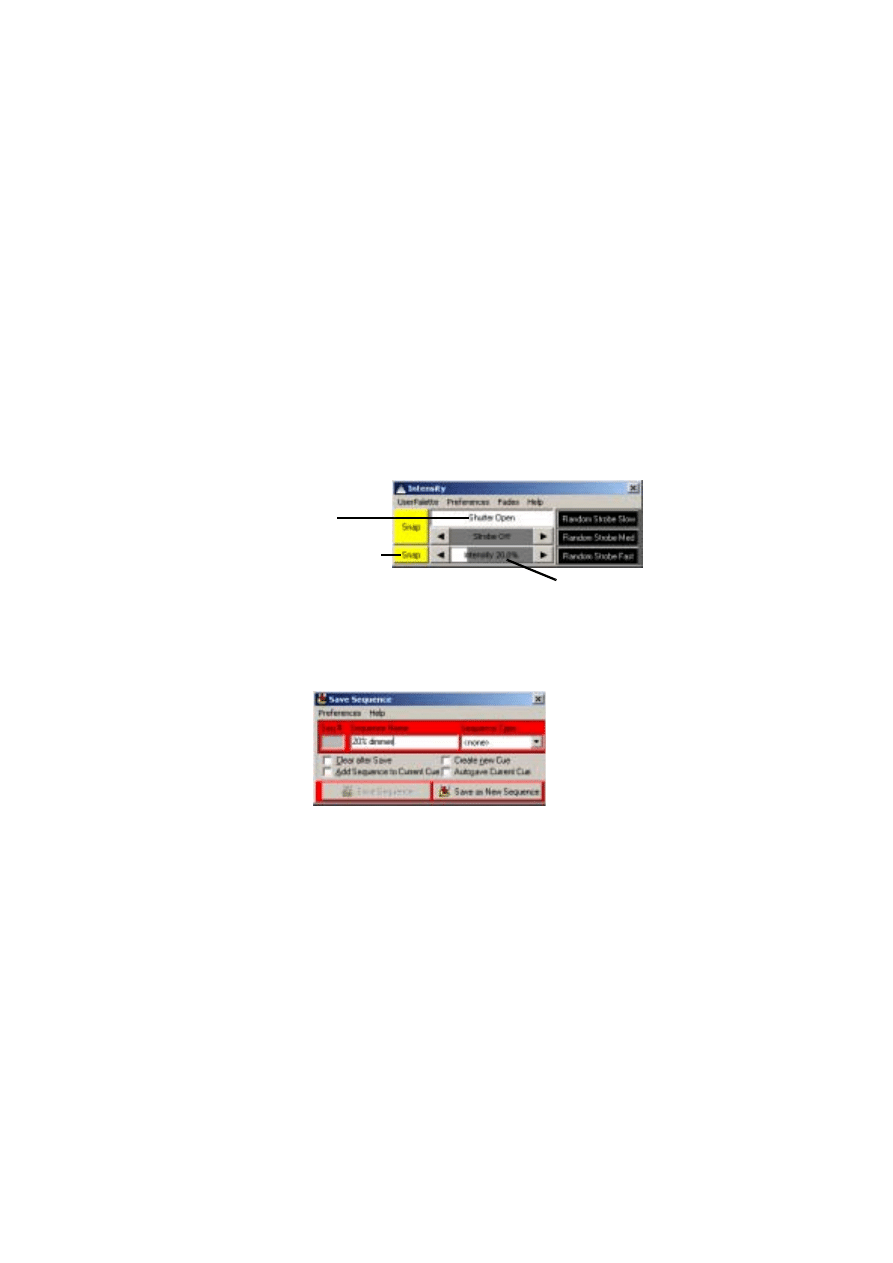
8.
In the
Intensity
dialog box click
Shutter Closed
.
Three things happen:
Shutter Closed
changes to
Shutter Open
, the shutter
Off/Snap/Fade button automatically changes to
Snap
, and the
Seq
field in the
Sequence toolbar changes from gray to yellow, indicating a change to the new
sequence.
9.
Click and drag the
Intensity
level to
20%
.
10.
Click the dimmer
Off
/
Snap
/
Fade
button twice until it is labelled
Snap
.
11.
Verify that your
Intensity
control looks like the one above and that the
Off
/
Snap
/
Fade
buttons in all the other open control dialog boxes appear as
Off
.
12.
Click the Save Sequence button in the Sequence toolbar.
13.
Type “20% dimmer” in the dialog’s Sequence Name field.
14.
Click
Save as New Sequence
or press Enter.
Shutter control
Dimmer Off/Snap/Fade
Dimmer level (% open)
5 6
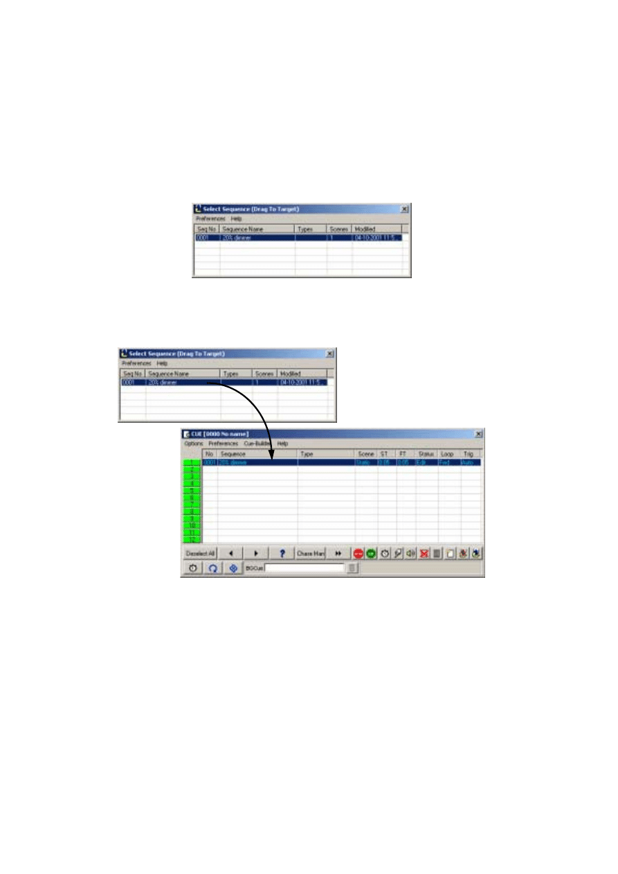
Step 2: Add sequence to cue
1.
Click the List of Sequences button on the Sequence toolbar. The
Select Sequence
(Drag To Target)
dialog box appears.
2.
Click the Toggle Cue Control button on the Cue toolbar. The
Cue [0000 No name]
dialog box appears.
3.
Drag the “20% dimmer” sequence to position 1 in the
Cue [0000 No name]
dialog
box. (If drag mode is not enabled, click
Preferences
→Drag mode
.) The Cue name
field changes from gray to yellow.
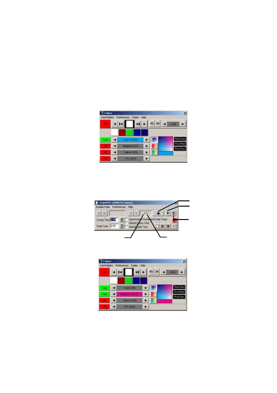
Step 3: Program color sequence
The next sequence is a CMY (cyan, magenta, yellow) color chase with 3 scenes. In the
first scene, cyan fades in and yellow, which comes in scene 3, fades out. In the second
scene, cyan fades out and magenta fades in. Finally, magenta fades out and yellow fades
in. The scene and fade times for each scene is set to three seconds for a smooth
continuous effect.
Drag and drop sequences
to cues.
5 7
1.
Close the
Select Sequence (Drag To Target)
and the
Cue [0000 No name]
dialog
boxes.
2.
Click the New/Clear Sequence button on the Sequence toolbar.
3.
Make sure both MAC 600s are selected: a fixture is selected when the icon label is
either light or dark red.
4.
Click the
Cyan
fader in the
Colors
dialog box, and drag it to
100%
. The associated
Off
/
Snap
/
Fade
button automatically changes to
Fade
.
5.
Click
Seq
(Toggle sequence control) on the Sequence toolbar. The
Sequence [0000
No name]
dialog box appears.
6.
Click
Synchronize Scene and Fade Times
.
7.
Set the
Scene Time
and
Fade Time
to
3:00
(3 seconds).
8.
Click the Add Scene button.
9.
In the
Colors
dialog box, click and drag the
Cyan
fader to
0%
and click and drag the
Magenta
fader to
100%
.
Add Scene
Insert Scene
Delete Scene
Total Scenes
Current Scene
5 8
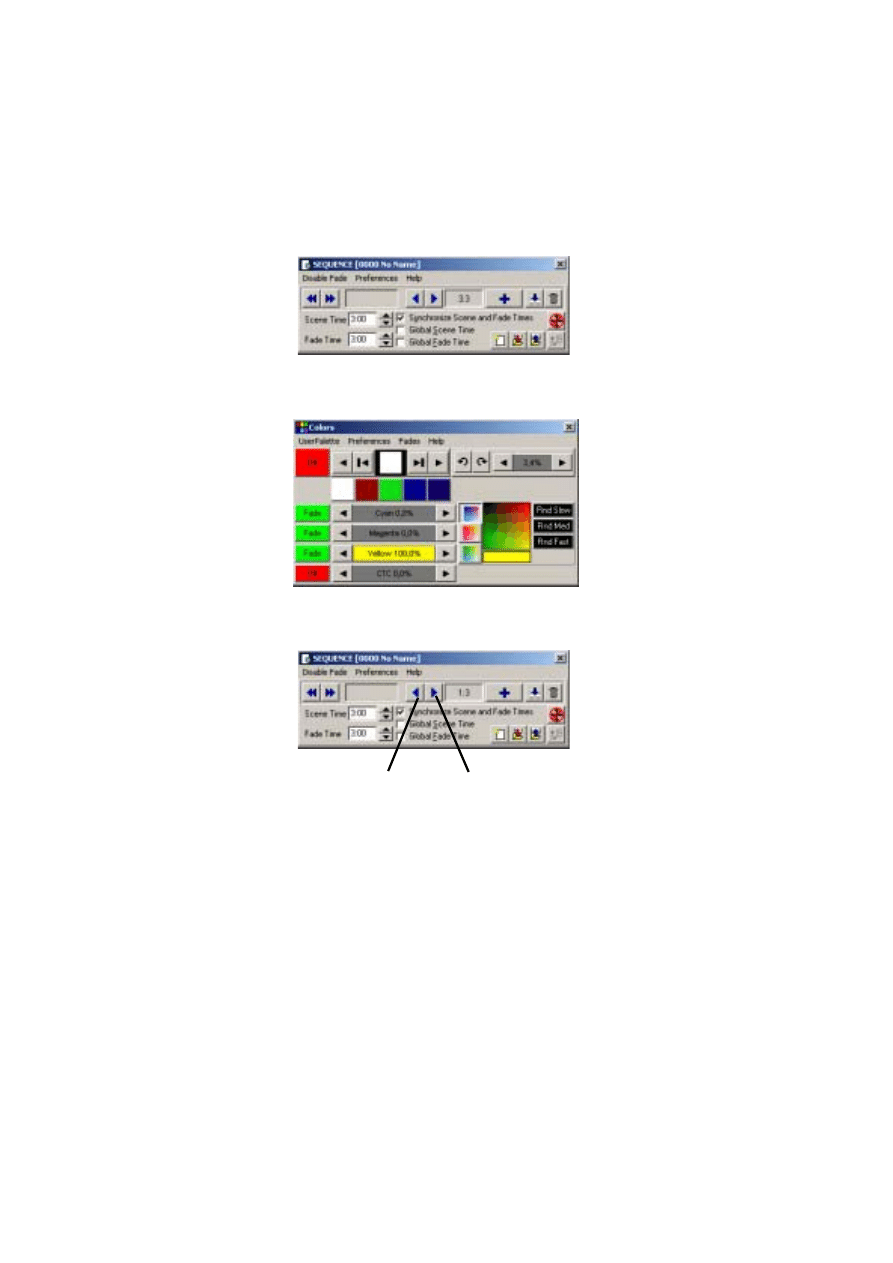
10.
In the
Sequence [0000 No name]
dialog box, click the Add Scene button
11.
In the
Colors
dialog box, click and drag the
Magenta
fader to
0%
and the
Yellow
fader to
100%
.
12.
To modify scene 1 so that it fades out yellow, click the Next Scene button in the
Sequence [0000 No name]
dialog box, to reach scene 1 (of 3)
Previous Scene
Next Scene
5 9
13.
In the
Colors
dialog box, click and drag
Yellow
to
0%.
Click the associated
Off
/
Snap
/
Fade
button until it is set to
Fade
.
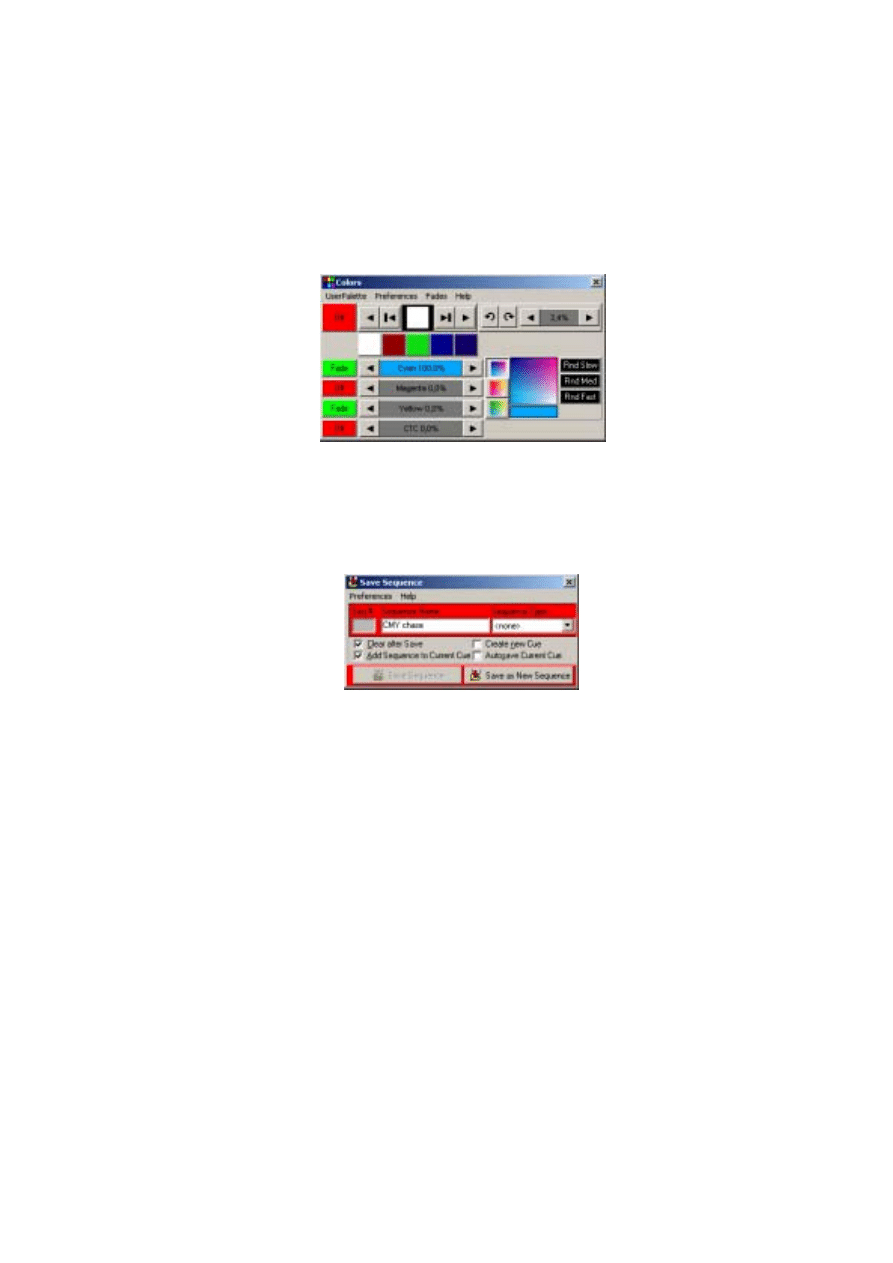
14.
Click the Save Sequence button in the
Sequence [0000 No name]
dialog box or
toolbar. The
Save Sequence
dialog box appears.
15.
Click
Clear after Save
and
Add Sequence to Current Cue
.
16.
Type
CMY chase
in
Sequence name
.
17.
Click
Save as New Sequence
or press Enter to save, clear, and add the sequence to
the current cue.
18.
Notice that the CMY faders in the
Colors
dialog box are now moving as the
sequence is performed.
Step 4: Program movement sequence
The LightJockey has a sophisticated effects engine for generating movements. This is
described in detail in the on-line help.
In this sequence you program each fixture individually to move in opposite directions.
1.
On the LightJockey desktop, click to select the
Left
MAC 600 (selection is indicated
by a red label) and deselect the
Right
MAC 600 (non selected fixtures appear with
blue labels).
2.
If the
Movement 16 Bit
dialog box is not open, click the Movement button on the
Fixture toolbar.
3.
Using the
Movement 16 Bit
dialog box, click and drag the round white movement
cursor to the middle of the top-right quadrant.
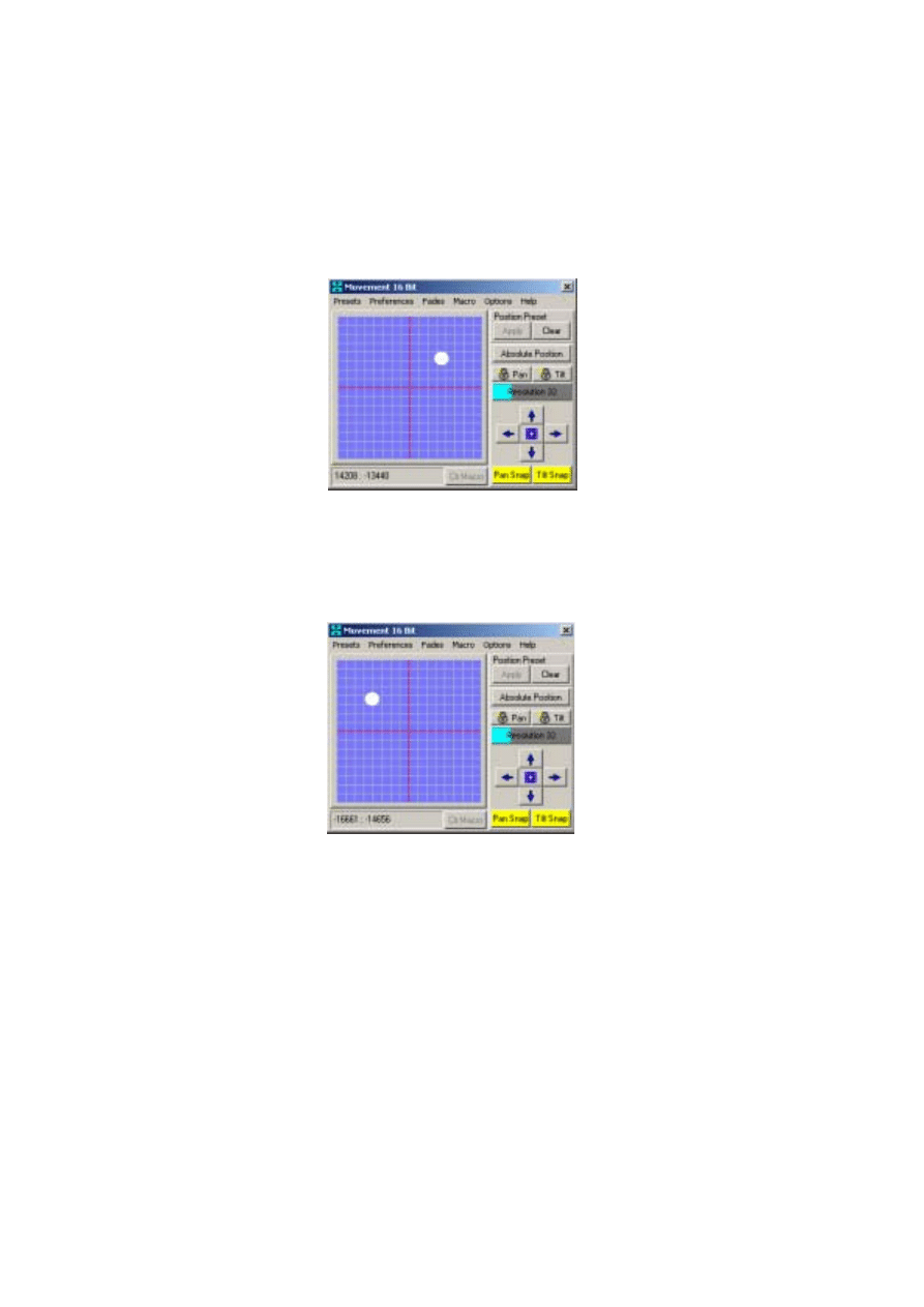
6 0
4.
Click the
Pan Off
/
Snap
/
Fade
and the
Tilt Off
/
Snap
/
Fade
buttons until they are set to
Snap
.
5.
On the LightJockey desktop, click to deselect the
Left
MAC 600 and select the
Right
MAC 600.
6.
Using the
Movement 16 Bit
dialog box, click and drag the round white movement
cursor to the middle of the top-left quadrant.
7.
Click the
Pan Off
/
Snap
/
Fade
and the
Tilt Off
/
Snap
/
Fade
buttons until they are set to
Snap
.
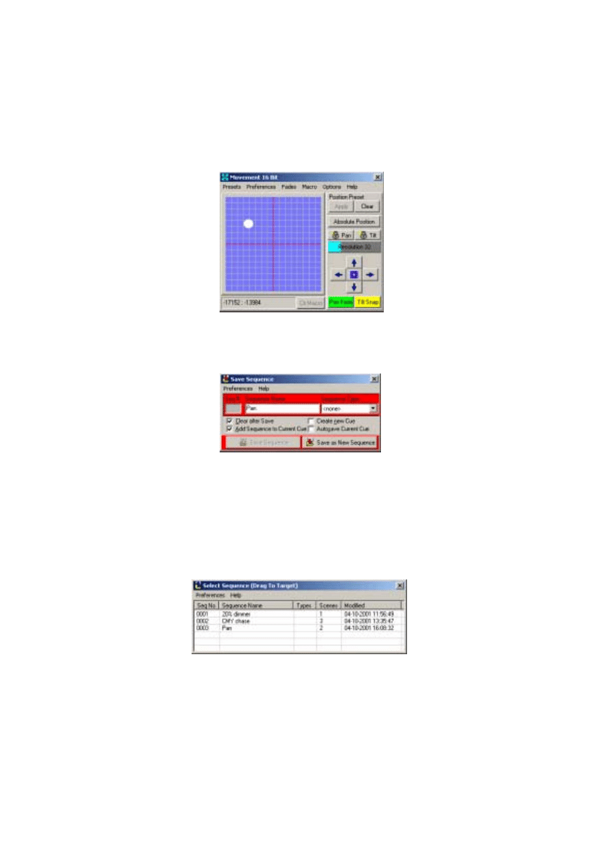
8.
In the
Sequence [0000 No name]
dialog box (which can be opened by clicking the
Seq
button on the Sequence toolbar), set the
Scene Time
to
2:00
. Note that if the
Synchronize Scene and Fade Times
check box is checked, then the
Fade Time
6 1
will automatically be set to
2:00
seconds as well. Here it makes no difference
because the effect is programmed to snap.
9.
Click the Add Scene button in the
Sequence [0000 No name]
dialog box.
10.
Set the scene and fade times to 15 seconds.
11.
Using the
Movement 16 Bit
dialog box, click and drag the round white movement
cursor to the middle of the top-right quadrant.
12.
Click the
Pan Off
/
Snap
/
Fade
buttons until it is set to
Fade
.
13.
On the LightJockey desktop, click to deselect the
Right
MAC 600 and select the
Left
MAC 600.
14.
Using the
Movement 16 Bit
dialog box, click and drag the round white movement
cursor to the middle of the top-left quadrant.
6 2
15.
Click the
Pan Off
/
Snap
/
Fade
buttons until it is set to
Fade
.
16.
Click the Save Sequence button on the Sequence toolbar. The
Save Sequence
dialog box appears.
17.
Type
Pan
in
Sequence Name
.
18.
Click
Save as New Sequence
or press Enter.
When you select the
Left
Mac 600 the round white movement cursor should move
slowly from left to right. The opposite will occur when you select the
Right
Mac
600.
Step 5: Edit movement sequence
Here you edit the pan sequence to black out both fixtures in the first scene.
1.
Click the List of Sequences button on the Sequence toolbar. The
Select Sequence
(Drag To Target)
dialog box appears.
2.
Click and drag the
Pan
sequence and drop it on to the LightJockey desktop.
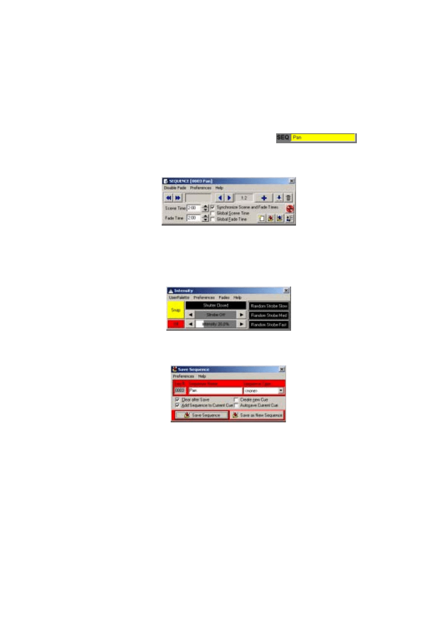
6 3
3.
Close the
Select Sequence (Drag To Target)
dialog
box. Notice that the cursor in the Movement control
stopped moving and the name of the sequence is
displayed in the Sequence name field.
4.
In the
Sequence [0000 No name]
dialog box (which
can be opened by clicking the
Seq
button on the Sequence toolbar), click the Next
Scene button to advance to scene 1.
5.
Select both MAC 600 fixtures on the LightJockey desktop.
6.
Click the
Shutter Closed
/
Open
button in the
Intensity
dialog box (which can be
opened by clicking the Intensity button on the Fixture toolbar) so that it changes to
Shutter Closed
.
7.
If necessary, click the shutter
Off
/
Snap
/
Fade
button (the top one of the two) so that it
is set to
Snap
.
8.
Click the Save Sequence button on the Sequence toolbar. The
Save Sequence
dialog box appears.
9.
Click
Save Sequence
or press Enter. A confirmation dialog box appears.
10.
Click
OK
to confirm.
Step 6: Save the cue
Cues are handled much like sequences.
1.
Click the Save Cue button on the Cue toolbar. The
Save Cue
dialog box appears.
2.
Type
M600 CMY pan
in
Cue Name
.
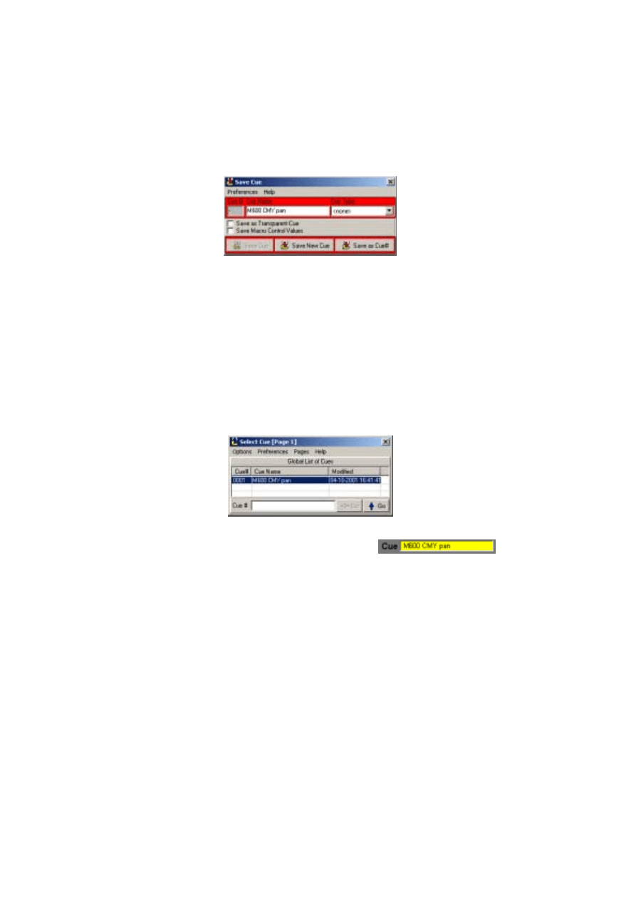
6 4
3.
Click
Save New
or press Enter.
Step 7: Edit the cue
This step demonstrates how sequence order effects cue playback. Look at the Intensity
control: the shutter closes for 2 seconds because of the command in the pan sequence.
This sequence has the highest priority because it is closest to the bottom. When you put
the 20% dimmer sequence underneath the pan sequence, the 20% dimmer sequence takes
priority and keeps the shutter open all the time. With a little planning, you can create
different looks using the same sequences just by changing their order.
1.
Click the New/Clear Cue button on the Cue toolbar to clear the cue from the
LightJockey desktop. (This is not required; it helps demonstrate how to load cues.)
2.
Click the List of Cues button on the Cue toolbar. The
Select Cue [Page 1]
dialog box
appears.
3.
Click and drag the
M600 CMY pan
cue and drop it
on to the LightJockey desktop. Its name appears in
the
Cue
field and the cue begins to run.
4.
Close the
Select Cue [Page 1]
dialog box to clear
space on the LightJockey desktop.
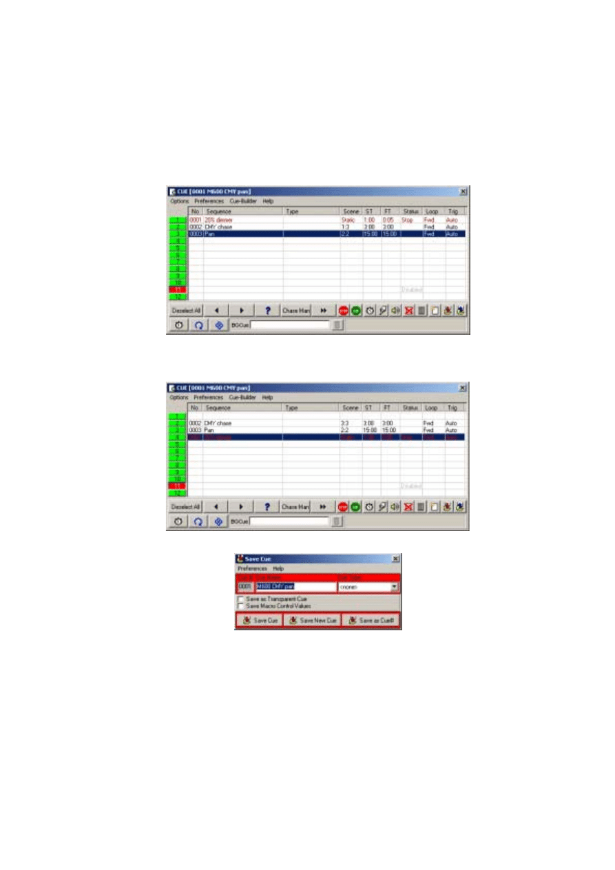
6 5
5.
Click the
Cue
(Toggle Cue Control) button on the Cue toolbar. The
Cue [0001 M600
CMY pan]
dialog box appears.
6.
Click and drag the
20% dimmer
sequence from position 1 and drop it on to position
4. A pop-up menu appears.
7.
Select
Move Sequence
.
8.
Click the Save Cue button. The
Save Cue
dialog box appears.
9.
Click
Save Cue
. A confirmation dialog box appears.
10.
Click
OK
.
11.
If you now look at the
Intensity
dialog box, note that the shutter now stays open all
the time.

6 6
Additional cue operations
When editing cues, the current sequence has highest priority. Normal cue execution
resumes when the current sequence is cleared. Note too that to synchronize the sequences
in the current cue, you must clear the cue and reload it onto the desktop.
•
To create a new cue and/or clear the current one, click the New/Clear Cue button on
the Cue toolbar.
•
To load a cue, click the List of Cues button on the Cue toolbar, and then click and
drag the cue from the
Select Cue [Page 1]
dialog box and drop it on the desktop.
Click the
Cue
(Toggle Cue Control) button on the Cue toolbar to open the
Cue [Cue-
Number Cue-Name]
dialog box. This dialog box is used to add, remove, rearrange,
and loaded cues.
•
To adjust cue timing, click the
Cue
(Toggle Cue Control) button on the Cue toolbar
to open the
Cue [Cue-Number Cue-Name]
dialog box. Click on the Cue Time
Control button at the lower-left of the dialog-box. The cue master fader adjusts times
(as a percent) for all sequences set to
CUE
time. Setting a sequence fader to another
value overrides the master cue fader.
2532 Direct Access Controller
The LightJockey supports the Martin 2532 Direct Access Controller, which can be used
to play back cues and sequences.
1.
Connect the 2532 to a serial (COM) port on the LightJockey computer.
2.
Apply power to the 2532.
3.
Click
Setup
→Hardware Setup...
to open the
Hardware Setup
dialog box.
4.
Click
Direct Access (via RS323)
.
5.
Click
Enabled
.
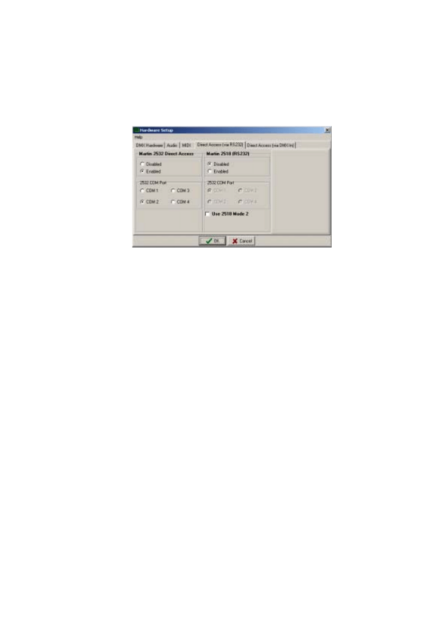
6 7
6.
Click the appropriate
COM
port.
7.
Click
OK
. A window will appear advising that LightJockey will need to be restarted
for the changes to take effect.
8.
Click
Yes
. LightJockey will shut down and then re-start.
9.
Click the 2532 Direct Access button on the Cue List toolbar to open the
2532 Direct
Access
dialog box. For more information see the on-line help.
Document Outline
- Installation
- Hardware installation
- Windows 2000 or Windows XP
- Installing the LightJockey PCI card on a Windows 2000/XP sys tem
- Installing the LightJockey 4064 ISA card on a Windows 2000/XP system
- Installing the LightJockey PCMCIA interface on a Windows 2000/XP system
- Installing the LightJockey USB/DMX interface on a Windows 2000 system
- Installing the LightJockey USB/DMX interface on a Windows XP system
- Windows 95, Windows 98, or Windows ME
- Installing the LightJockey PCI card on a Windows 95/98/ME system
- Installing the LightJockey 4064 ISA card on a Windows 95/98/ME system
- Installing the LightJockey ADP parallel port interface on a Windows 95/98/ME system
- Installing the LightJockey PCMCIA interface on a Windows 95/98/ME system
- Installing the LightJockey USB/DMX interface on a Windows 95/98/ME system
- Notes on removing the PCI/ISA driver
- Windows 2000 or Windows XP
- Software installation
- Hardware configuration
- Connecting the serial data link
- Hardware installation
- Introduction to programming
- Identifying the controls
- Configuring fixtures
- Configuring the desktop
- Striking lamps
- Programming cues
- Cue building blocks
- Bottom to top cue execution
- Outline of programming steps
- Creating new cues
- Creating and editing sequences
- Selecting fixtures
- Programming effects
- Setting the Off/Snap/Fade control
- Setting scene and fade times
- Adding, inserting, and deleting scenes
- Saving sequences
- Adding sequences to a cue
- Saving cues
- Example: Programming a cue
- Additional cue operations
- 2532 Direct Access Controller
Wyszukiwarka
Podobne podstrony:
CSharp Introduction to C# Programming for the Microsoft NET Platform (Prerelease)
Manual Way to UNLOCK ESTIMATES in Alldata for Windows
How to Design Programs An Introduction to Computing and Programming Matthias Felleisen
Introduction to Lagrangian and Hamiltonian Mechanics BRIZARD, A J
Introduction to the MOSFET and MOSFET Inverter(1)
Introduction to CPLD and FPGA Design
Introduction to Mechatronics and Measurement Systems
An Introduction to Extreme Programming
Introduction to Prana and Pranic Healing – Experience of Breath and Energy (Pran
introduction to tcp ip programming itepxv25ma7bwpg7fc2zotnflwzvijoaktevssq ITEPXV25MA7BWPG7FC2ZOTNFL
An Introduction to USA 1 The Land and People
An Introduction to USA 4 The?onomy and Welfare
An Introduction to USA 7 American Culture and Arts
Introduction to Microprocessors and Microcontrollers
An Introduction to USA 5 Science and Technology
Poisonous and Edible Mushrooms An Introduction to Mushrooms in Norway (2012)
An Introduction to USA 3 Public Life and Institutions
więcej podobnych podstron