SMALL CIRCUITSCOLLECTION
88
Elektor Electronics
12/2002
J. Swart
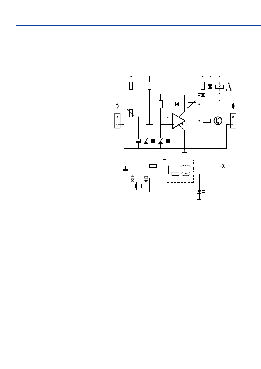
At last there is another project for caravan own-
ers. They are probably all aware of the prob-
lems of a flat battery when they’ve forgotten to
turn off the fridge after the engine has been
switched off. When this circuit is installed
between the fridge and (caravan) battery, these
troubles will be a thing of the past. This simple,
but smart, switch reacts to the increase in volt-
age that occurs when the engine is running.
Whereas the normal battery voltage is 12 V, this
increases to a minimum of 13.8 V when the
alternator charges it. With a suitably configured
comparator this voltage difference can easily be
detected, and as can be seen, the circuit con-
sists of little more than a 3140 comparator and
a relay driver stage for switching the fridge.
P1 sets the voltage at the non-inverting input of
the comparator such that the relay will only be
powered when the battery voltage is above
13.8 V, so only when the engine is running. The
hysteresis introduced by D1/P2 stops the relay
from turning off as soon as the engine stops
and the battery voltage drops a little. P2 is used
to set the exact cut-off point and this preset
should be set to a voltage at which the battery has not dis-
charged too much; 11.5 V would be a suitable value. The
fridge remains working until the battery voltage drops to this
critical level, at which point it will turn off.
It is the intention that the circuit is mounted inside the cara-
van, between the fridge and the 12 V line coming from the car.
This assumes that a 7-pin trailer socket is used, which has a
single constant supply on pin 2. When a 13-pin connector is
used, the circuit could also be mounted inside the car and
switch the battery voltage going to pin 10. The fridge should
obviously be powered via this pin too.
Here’s a tip: The circuit isn’t limited just for use with fridges.
The same circuit could for example be used to automatically
switch on the car lights whilst the engine is running. This really
is a multi-purpose circuit.
For those of you who wish to verify that the circuit operates
correctly, the author has designed a LED indicator that lights up
when a current greater than 3 A is drawn from the supply. A
special property of this circuit is that it introduces virtually no
voltage drop in the supply. It consists of little more than a reed
switch with several turns of 4 mm diameter wire wound round
it (8 turns were found to be sufficient for the prototype). The
reed switch is turned on by the magnetic flux created by the
coil and switches on a LED that can be mounted on the dash-
board. The reed switch and coil would fit perfectly in a 35mm
film canister.
(024007-1)
049
R3
47k
R4
330k
R5
1k
R7
1k
100k
P1
100k
P2
R6
10k
T1
2N2219
C1
1
µ
C2
100n
C3
100n
D2
9V1
D3
4V7
D1
BAV21
CA3140
IC1
2
3
6
7
4
1
8
5
Re1
D5
BAV21
D4
K1
K2
+12V
0V
+12V
0V
024007 - 11
1N4148
1N4148
25V
400mW
400mW
L1
S1
R1
1k
+12V
D1
16A
F1
024007 - 12
12V
BATTERY
red
Automatic Fridge Switch
for Caravans
The circuit diagram shows a switched-capacitor voltage
inverter with +5-V input and –3-V output, along with a sup-
plementary cascade stage to generate a +17-V auxiliary volt-
age. The capacitor connected to the CP– and CP+ terminals
assists in inverting the input voltage. During the first clock
phase it is charged to the input voltage, while during the sec-
ond clock phase its positive terminal is connected to ground
while its other terminal is connected to the output. This gen-
050
Voltage Inverter with Cascade Stage
erates a negative voltage at the output, with an amplitude
equal to the input voltage. Using the duty cycle, the IC
described here generates a regulated output voltage of –3 V
with a current capacity of 120 mA.
The clocked operation makes it possible to connect an addi-
tional diode cascade stage for voltage multiplication. This con-
sists of a series of diodes (for instance, type SS24 SMD Schot-
tky diodes) with alternating pump and storage capacitors. The
pump capacitors are connected to CP+ and charge when CP+
is at ground potential. When CP+ goes to a high-potential
level, the potentials on the upper plates of the pump capaci-
tors are pushed up. Each pump capacitor then discharges into
the following storage capacitor (connected to ground) via the
intermediate diode. The voltage increases with each pump
stage, resulting in a net voltage of around +17 V after three
voltage boosts, with a maximum load capacity of 3 mA.
The type ADP3605 IC is available from Analog Devices
(
www.analog.com/productSelection/pdf/ADP3605_a.pdf
) and
is housed in an SO8 SMD package. A High level (> +2.4 V)
SMALL CIRCUITSCOLLECTION
89
12/2002
Elektor Electronics
can be applied to the Shutdown input (SD) to disable the
converter.
(024091-1)
C1
1
µ
C9
2
µ
2
C2
2
µ
2
C3
2
µ
2 16V
D1
D2
ADP3605
VSENSE
IC1
VOUT
VIN
CP+
CP–
SD
7
2
4
8
1
3
5
D3
D4
D5
D6
C5
1
µ
16V
C7
1
µ
16V
C4
2
µ
2 10V
C6
1
µ
16V
+17V
+5V
R1
10k
SHUTDOWN
–3V
024091 - 11
D1...D6 = SS24
3mA
120mA
E. Potters
Some time ago, the author built a copy of the IGBT Power
Amp, a final amplifier design described in the June 1995 issue
of Elektor Electronics that has since become a classic. The
sound quality provided by the amplifier was more than superb,
but it was evident that the output transistors became quite hot
during full-power testing (at 140 W). This is not uncommon,
of course, but it set an alarm bell ringing, and it was deemed
a good idea to at least add DC protection to safeguard the
(expensive) amplifier and equally expensive speakers.
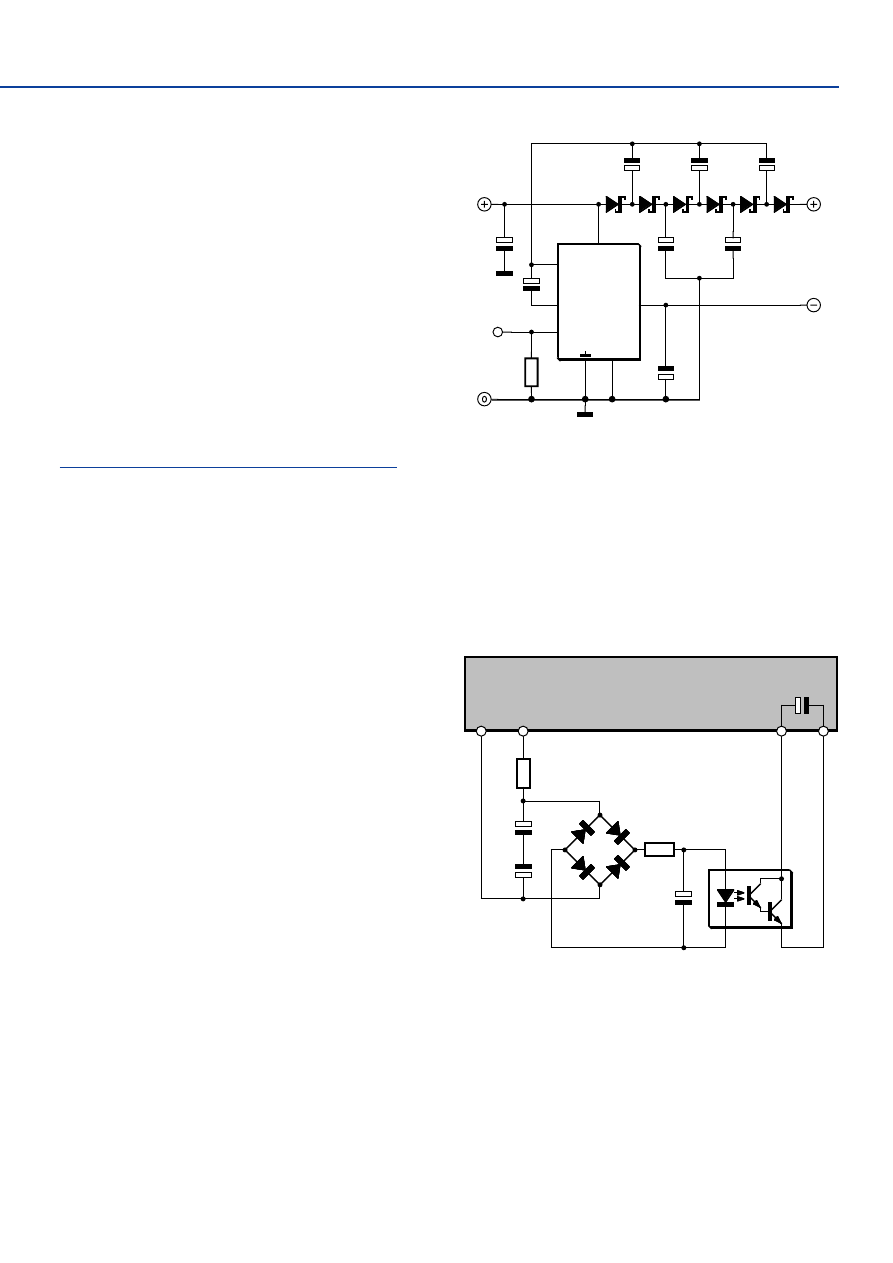
The accompanying schematic diagram shows the simplic-
ity the necessary extension, which naturally can also be used
with the Hexfet Power AMP described in the November 1993
issue (which is identical in terms of overall design). All that is
involved is an optoisolator that monitors output terminal A of
the amplifier via a bridge rectifier and series resistor, and
whose output is connected in parallel with C14 in the relay
control stage. This circuit can be used for all amplifiers up to
a DC voltage of 70 V. For higher voltages, the value of R1 must
be modified. When a voltage of approximately 2 V
DC
is pre-
sent at the input, the phototransistor in IC1 starts to conduct,
causing C14 in the amplifier to discharge and disconnect the
loudspeaker from the amplifier output by releasing the relay.
If you want to replace the MOC8030 by a different type, be
sure to use a Darlington type (or fit an additional transistor)
on account of the dynamic range. Also, pay attention to the
maximum diode current, which is 80 mA for the MOC8030.
Another incidental point is that the IGBT Power Amp has a
tendency to start oscillating if RF1 and RF2 are not low-induc-
tance types or are replaced by other types of low-inductance
resistors. In order to eliminate this problem once and for all,
the following modification has been developed in the Elektor
Electronics labs:
– Fit a 27-nF capacitor in parallel with R31 (on the solder side).
– Insert a 20-k
Ω
resistor between the collector of T8 and
ground.
– Change R20 to 1k8.
– Change R17 and R18 to 390
Ω
.
051
MOC8030
IC1
5
4
1
2
C3
100
µ
25V
C1
220
µ
40V
C1
220
µ
40V
C14
R2
GND
A
10
Ω
R1
HEXFET / IGBT
Power - Amp
1k
5W
D1
D4
D2
D3
4x 1N4007
024029 - 11
DC Protection for the
IGBT Power Amp
Wyszukiwarka
Podobne podstrony:
Modified PWM Control for the DC AC Inverter With a Non Constant Voltage Source
A ZVS PWM Inverter With Active Voltage Clamping Using the Reverse Recovery Energy of the Diodes
The Discrete Time Control of a Three Phase 4 Wire PWM Inverter with Variable DC Link Voltage and Bat
The Discrete Time Control of a Three Phase 4 Wire PWM Inverter with Variable DC Link Voltage and Bat
Modified PWM Control for the DC AC Inverter With a Non Constant Voltage Source
00329965 Quasi Parallel Resonant Dc Link Inverter With Improved Pwm Capability
[DI] Circuit makes simple high voltage inverter
A Novel Switch Mode Dc To Ac Inverter With Nonlinear Robust Control
A Novel Switch mode DC to AC Inverter With Non linear Robust Control
Pulse controlled inverter with variable operating sequence and wind power plant having such an inver
A Novel Switch Mode Dc To Ac Inverter With Non Linear Robust Control
Dc To Ac Inverter With The 555
SN7414 Hex Inverter with Schmitt Trigger Input
00329965 Quasi Parallel Resonant Dc Link Inverter With Improved Pwm Capability
edn0604 Circuit makes simple high voltage inverter
A Novel Switch Mode Dc To Ac Inverter With Non Linear Robust Control(1)
więcej podobnych podstron