
Issued: 10.04.20
Issued: 10.04.2008 Version: BA Multibus PB Master V1 en
KUKA Robot Group
Controller Option
Multibus Interface Profibus Master
For KR C2 edition2005
Operating Instructions

© Copyright 2008
KUKA Roboter GmbH
Zugspitzstraße 140
D-86165 Augsburg
Germany
This documentation or excerpts therefrom may not be reproduced or disclosed to third parties without
the express permission of the KUKA ROBOT GROUP.
Other functions not described in this documentation may be operable in the controller. The user has no
claims to these functions, however, in the case of a replacement or service work.
We have checked the content of this documentation for conformity with the hardware and software de-
scribed. Nevertheless, discrepancies cannot be precluded, for which reason we are not able to guaran-
tee total conformity. The information in this documentation is checked on a regular basis, however, and
necessary corrections will be incorporated in the subsequent edition.
Subject to technical alterations without an effect on the function.
KIM-PS5-DOC
V0.4 22.03.200
6 pub de
Multibus Interface Profibus Master
Issued: 10.04.2008 Version: BA Multibus PB Master V1 en
Publication:
Pub BA KR C2 ed05 Multibus-Schnittstelle Profibus-Master en
Book structure: BA KR C2 ed05 Multibus-Schnittstelle Profibus-Master V1.2
Label:
BA Multibus PB Master V1

Issued: 10.04.2008 Version: BA Multibus PB Master V1 en
Contents
Introduction ......................................................................................................
5
Target group ...................................................................................................................
5
Robot system documentation .........................................................................................
5
Representation of warnings and notes ...........................................................................
5
Terms used .....................................................................................................................
5
Product description .........................................................................................
7
Overview of the robot system .........................................................................................
7
Overview of the robot controller ......................................................................................
7
Description of the Multibus interface, Profibus master ...................................................
8
Profibus master X61 .......................................................................................................
9
Safety ................................................................................................................
11
KUKA Service ...................................................................................................
13
Requesting support .........................................................................................................
13
KUKA Customer Support ................................................................................................
13
Contents

Issued: 10.04.2008 Version: BA Multibus PB Master V1 en
1. Introduction
1
Introduction
1.1
Target group
This documentation is aimed at users with the following knowledge and skills:
Advanced knowledge of electrical and electronic systems
Advanced knowledge of the robot controller
Advanced knowledge of the Windows operating system
1.2
Robot system documentation
The robot system documentation consists of the following parts:
Operating instructions for the robot
Operating instructions for the robot controller
Operating and programming instructions for the KUKA System Software
Documentation relating to options and accessories
Each of these sets of instructions is a separate document.
1.3
Representation of warnings and notes
Safety
Warnings marked with this pictogram are relevant to safety and must be ob-
served.
Notes
Notes marked with this pictogram contain tips to make your work easier or ref-
erences to further information.
1.4
Terms used
Danger!
This warning means that death, severe physical injury or substantial material
damage will occur, if no precautions are taken.
Warning!
This warning means that death, severe physical injury or substantial material
damage may occur, if no precautions are taken.
Caution!
This warning means that minor physical injuries or minor material damage
may
occur, if no precautions are taken.
Tips to make your work easier or references to further information.
Term
Description
ESC
Electronic Safety Circuit
KCP
Teach pendant (KUKA Control Panel)

Issued: 10.04.2008 Version: BA Multibus PB Master V1 en
Multibus Interface Profibus Master
US1
24 V DC supply voltage for bus logic and sen-
sors (bus voltage)
US2
24 V DC supply voltage for actuators (actuator
voltage)
Term
Description
Issued: 10.04.2008 Version: BA Multibus PB Master V1 en
2. Product description
2
Product description
2.1
Overview of the robot system
The robot system consists of the following components:
Robot
Robot controller
KCP teach pendant
Connecting cables
Software
Options, accessories
2.2
Overview of the robot controller
The robot controller is used for controlling the following systems:
KUKA robots
KMC
External kinematic system
The robot controller consists of the following components:
Control PC
Power unit
KCP teach pendant
Safety logic ESC
Connection panel
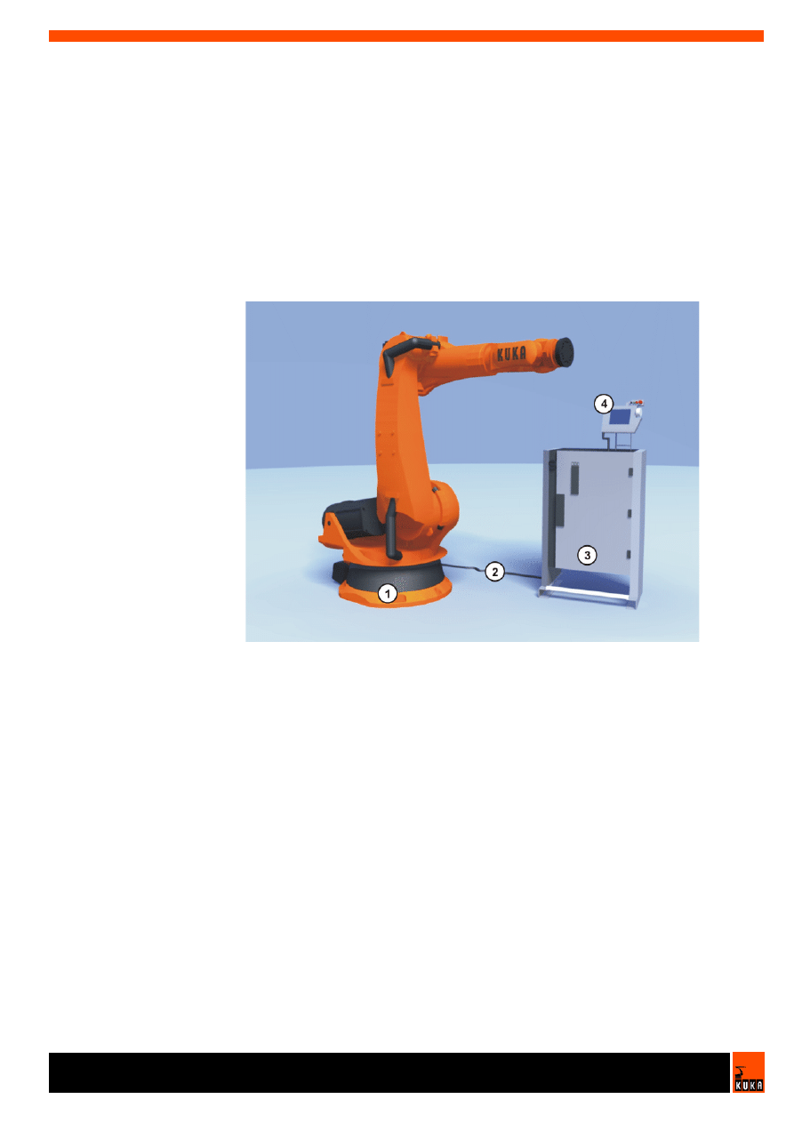
Fig. 2-1: Example of a robot system
1
Robot
3
Robot controller
2
Connecting cables
4
Teach pendant
Issued: 10.04.2008 Version: BA Multibus PB Master V1 en
Multibus Interface Profibus Master
2.3
Description of the Multibus interface, Profibus master
Overview
The connection panel of the control cabinet consists as standard of connec-
tions for the following cables:
Power cable / infeed
Motor cables to the robot
Control cables to the robot
KCP connection
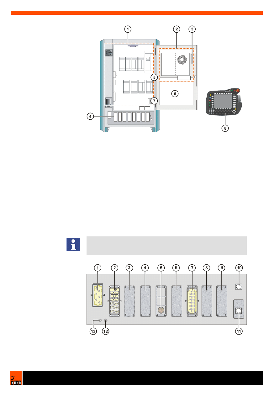
Connection panel
Fig. 2-2: Overview of the robot controller
1
Power unit
4
Connection panel
2
Control PC
5
Mounting plate for customer
components
3
Safety logic (ESC)
6
KCP
The configuration of the connection panel varies according to the customer-
specific version and the options required. The Profibus master connector
X61 can be installed in position 5, 6, 8 or 9.
Fig. 2-3: Example: connection panel with Multibus interface

Issued: 10.04.2008 Version: BA Multibus PB Master V1 en
2. Product description
2.4
Profibus master X61
Description
The supply voltages US1 and US2 are fed in via interface X11.
1
X1/XS1 power supply connec-
tion
8
Optional
2
X20 motor connection
9
Optional
3
Optional
10
X19 KCP connection
4
Optional
11
X21 RDC connection
5
X61 Profibus connection
12
PE1 ground conductor to the
robot
6
Optional
13
PE2 main infeed ground con-
ductor
7
X11 interface
Note
All contactor, relay and valve coils that are connected to the robot controller
by the user must be equipped with suitable suppressor diodes. RC elements
and VCR resistors are not suitable.
Further information is contained in the robot controller operating instructions.
Further information about interface X11 is contained in the KR C2
edition2005 operating instructions.
Issued: 10.04.2008 Version: BA Multibus PB Master V1 en
Multibus Interface Profibus Master
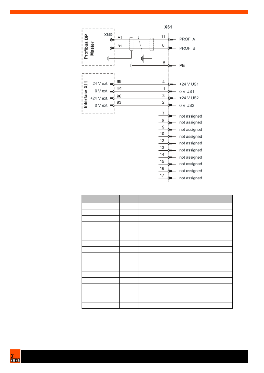
Connector pin
allocation
Fig. 2-4: Connector pin allocation, X61, Profibus master
Signal
Pin
Description
0 V US1
1
0 V load voltage US1
0 V US2
2
0 V load voltage US2
+24 V US2
3
+24 V load voltage US2
+24 V US1
4
+24 V load voltage US1
PE
5
Ground conductor
PROFI B
6
Profibus B
PROFI A
11
Profibus A
-
7
not assigned
-
8
not assigned
-
9
not assigned
-
10
not assigned
-
12
not assigned
-
13
not assigned
-
14
not assigned
-
15
not assigned
-
16
not assigned
-
17
not assigned

Issued: 10.04.2008 Version: BA Multibus PB Master V1 en
3. Safety
3
Safety
Operator
The operator must meet the following preconditions:
The operator must have read and understood the robot system documen-
tation, including the safety chapter.
The operator must be trained for the work to be carried out.
Work on the robot system must only be carried out by qualified personnel.
These are people who, due to their specialist training, knowledge and ex-
perience, and their familiarization with the relevant standards, are able to
assess the work to be carried out and detect any potential dangers.


Issued: 10.04.2008 Version: BA Multibus PB Master V1 en
4. KUKA Service
4
KUKA Service
4.1
Requesting support
Introduction
The KUKA Robot Group documentation offers information on operation and
provides assistance with troubleshooting. For further assistance, please con-
tact your local KUKA subsidiary.
Information
The following information is required for processing a support request:
Model and serial number of the robot
Model and serial number of the controller
Model and serial number of the linear unit (if applicable)
Version of the KUKA System Software
Optional software or modifications
Archive of the software
Application used
Any external axes used
Description of the problem, duration and frequency of the fault
4.2
KUKA Customer Support
Availability
KUKA Customer Support is available in many countries. Please do not hesi-
tate to contact us if you have any questions.
Argentina
Ruben Costantini S.A. (Agency)
Luis Angel Huergo 13 20
Parque Industrial
2400 San Francisco (CBA)
Argentina
Tel. +54 3564 421033
Fax +54 3564 428877
ventas@costantini-sa.com
Australia
Marand Precision Engineering Pty. Ltd. (Agency)
153 Keys Road
Moorabbin
Victoria 31 89
Australia
Tel. +61 3 8552-0600
Fax +61 3 8552-0605
robotics@marand.com.au
Faults leading to production downtime are to be reported to the local KUKA
subsidiary within one hour of their occurrence.

Issued: 10.04.2008 Version: BA Multibus PB Master V1 en
Multibus Interface Profibus Master
Austria
KUKA Roboter GmbH
Vertriebsbüro Österreich
Regensburger Strasse 9/1
4020 Linz
Austria
Tel. +43 732 784752
Fax +43 732 793880
office@kuka-roboter.at
www.kuka-roboter.at
Belgium
KUKA Automatisering + Robots N.V.
Centrum Zuid 1031
3530 Houthalen
Belgium
Tel. +32 11 516160
Fax +32 11 526794
info@kuka.be
www.kuka.be
Brazil
KUKA Roboter do Brasil Ltda.
Avenida Franz Liszt, 80
Parque Novo Mundo
Jd. Guançã
CEP 02151 900 São Paulo
SP Brazil
Tel. +55 11 69844900
Fax +55 11 62017883
info@kuka-roboter.com.br
Chile
Robotec S.A. (Agency)
Santiago de Chile
Chile
Tel. +56 2 331-5951
Fax +56 2 331-5952
robotec@robotec.cl
www.robotec.cl
China
KUKA Flexible Manufacturing Equipment (Shanghai) Co., Ltd.
Shanghai Qingpu Industrial Zone
No. 502 Tianying Rd.
201712 Shanghai
P.R. China
Tel. +86 21 5922-8652
Fax +86 21 5922-8538
Franz.Poeckl@kuka-sha.com.cn
www.kuka.cn

Issued: 10.04.2008 Version: BA Multibus PB Master V1 en
4. KUKA Service
France
KUKA Automatisme + Robotique SAS
Techvallée
6 Avenue du Parc
91140 Villebon s/Yvette
France
Tel. +33 1 6931-6600
Fax +33 1 6931-6601
commercial@kuka.fr
www.kuka.fr
Germany
KUKA Roboter GmbH
Blücherstr. 144
86165 Augsburg
Germany
Tel. +49 821 797-4000
Fax +49 821 797-1616
info@kuka-roboter.de
www.kuka-roboter.de
Hungary
KUKA Robotics Hungaria Kft.
Fö út 140
2335 Taksony
Hungary
Tel. +36 24 501609
Fax +36 24 477031
info@kuka-robotics.hu
India
KUKA Robotics, Private Limited
621 Galleria Towers
DLF Phase IV
122 002 Gurgaon
Haryana
India
Tel. +91 124 4148574
info@kuka.in
www.kuka.in
Italy
KUKA Roboter Italia S.p.A.
Via Pavia 9/a - int.6
10098 Rivoli (TO)
Italy
Tel. +39 011 959-5013
Fax +39 011 959-5141
kuka@kuka.it
www.kuka.it

Issued: 10.04.2008 Version: BA Multibus PB Master V1 en
Multibus Interface Profibus Master
Korea
KUKA Robot Automation Korea Co. Ltd.
4 Ba 806 Sihwa Ind. Complex
Sung-Gok Dong, Ansan City
Kyunggi Do
425-110
Korea
Tel. +82 31 496-9937 or -9938
Fax +82 31 496-9939
info@kukakorea.com
Malaysia
KUKA Robot Automation Sdn Bhd
South East Asia Regional Office
No. 24, Jalan TPP 1/10
Taman Industri Puchong
47100 Puchong
Selangor
Malaysia
Tel. +60 3 8061-0613 or -0614
Fax +60 3 8061-7386
info@kuka.com.my
Mexico
KUKA de Mexico S. de R.L. de C.V.
Rio San Joaquin #339, Local 5
Colonia Pensil Sur
C.P. 11490 Mexico D.F.
Mexico
Tel. +52 55 5203-8407
Fax +52 55 5203-8148
info@kuka.com.mx
Norway
KUKA Sveiseanlegg + Roboter
Bryggeveien 9
2821 Gjövik
Norway
Tel. +47 61 133422
Fax +47 61 186200
geir.ulsrud@kuka.no
Portugal
KUKA Sistemas de Automatización S.A.
Rua do Alto da Guerra n° 50
Armazém 04
2910 011 Setúbal
Portugal
Tel. +351 265 729780
Fax +351 265 729782
kuka@mail.telepac.pt

Issued: 10.04.2008 Version: BA Multibus PB Master V1 en
4. KUKA Service
Russia
KUKA-VAZ Engineering
Jushnoje Chaussee, 36 VAZ, PTO
445633 Togliatti
Russia
Tel. +7 8482 391249 or 370564
Fax +7 8482 736730
Y.Klychkov@VAZ.RU
South Africa
Jendamark Automation LTD (Agency)
76a York Road
North End
6000 Port Elizabeth
South Africa
Tel. +27 41 391 4700
Fax +27 41 373 3869
www.jendamark.co.za
Spain
KUKA Sistemas de Automatización S.A.
Pol. Industrial
Torrent de la Pastera
Carrer del Bages s/n
08800 Vilanova i la Geltrú (Barcelona)
Spain
Tel. +34 93 814-2353
Fax +34 93 814-2950
Comercial@kuka-e.com
www.kuka-e.com
Sweden
KUKA Svetsanläggningar + Robotar AB
A. Odhners gata 15
421 30 Västra Frölunda
Sweden
Tel. +46 31 7266-200
Fax +46 31 7266-201
info@kuka.se
Switzerland
KUKA Roboter Schweiz AG
Riedstr. 7
8953 Dietikon
Switzerland
Tel. +41 44 74490-90
Fax +41 44 74490-91
info@kuka-roboter.ch
www.kuka-roboter.ch

Issued: 10.04.2008 Version: BA Multibus PB Master V1 en
Multibus Interface Profibus Master
Taiwan
KUKA Robot Automation Taiwan Co. Ltd.
136, Section 2, Huanjung E. Road
Jungli City, Taoyuan
Taiwan 320
Tel. +886 3 4371902
Fax +886 3 2830023
info@kuka.com.tw
www.kuka.com.tw
Thailand
KUKA Robot Automation (M)SdnBhd
Thailand Office
c/o Maccall System Co. Ltd.
49/9-10 Soi Kingkaew 30 Kingkaew Road
Tt. Rachatheva, A. Bangpli
Samutprakarn
10540 Thailand
Tel. +66 2 7502737
Fax +66 2 6612355
atika@ji-net.com
www.kuka-roboter.de
UK
KUKA Automation + Robotics
Hereward Rise
Halesowen
B62 8AN
UK
Tel. +44 121 585-0800
Fax +44 121 585-0900
sales@kuka.co.uk
USA
KUKA Robotics Corp.
22500 Key Drive
Clinton Township
48036 Michigan
USA
Tel. +1 866 8735852
Fax +1 586 5692087
info@kukarobotics.com
www.kukarobotics.com

Issued: 10.04.2008 Version: BA Multibus PB Master V1 en
Index
Index
C
Connecting cables 7
Connection panel 7
Control cables 8
Control PC 7
D
Description of the robot system 7
Documentation, robot system 5
K
KCP 5, 7
KCP connection 8
KUKA Customer Support 13
M
Motor cables 8
Multibus interface 8
O
Operator 11
Options 7
Overview of the robot controller 7
P
Power cable 8
Power unit 7
Product description 7
Profibus master 8
Profibus master, X61 9
R
Robot 7
Robot controller 7
Robot system 7
S
Safety 11
Safety instructions 5
Safety logic 7
Service, KUKA Roboter 13
Software 7
Support request 13


Document Outline
- Multibus Interface Profibus Master
Wyszukiwarka
Podobne podstrony:
PocketBook 613 RN PB 613 4 0 EN
easy500 Master reset HLP EN
BA norma EN
1 9 PN EN 1367 3 2002 Badania wl cieplnych i odpornosci kruszyw na dzialanie czynnikow atm Badanie b
BA MACH4 en Operator's Manual
Multiboot on Amiko Alien EN
BA KR C2 ed05 Main Switch with Cover en
Trampas en el baño Leontxo García
1 9 PN EN 1367 3 2002 Badania wl cieplnych i odpornosci kruszyw na dzialanie czynnikow atm Badanie b
Budzik Versa wielkość karty kredytowej instrukcja EN
G2 4 PW EN wn Rys 01
dane mastertig2300mls
Dz U 1997 109 704 R S u ba bezpiecze stwa i higi 3
Manual Acer TravelMate 2430 US EN
01 Certyfikat 650 1 2015 Mine Master RM 1 8 AKW M
więcej podobnych podstron