Design and construction of a three-phase transformer for a 1 kW multi-level
converter
Nancy Mondragón-Escamilla, Alejandro Villarruel-Parra, Ismael Araujo-Vargas, Juan Carlos
Sánchez-García
Email:
naytsu10@hotmail.com
,
alexvip_22@hotmail.com
School of Mechanical and Electrical Engineering, Postgraduate Section, SEPI-ESIME Culhuacan, National Polytechnic
Institute of Mexico, Av. Santa Ana No. 1000, Col. San Francisco Culhuacan, Del. Coyoacan, D.F.
Abstract
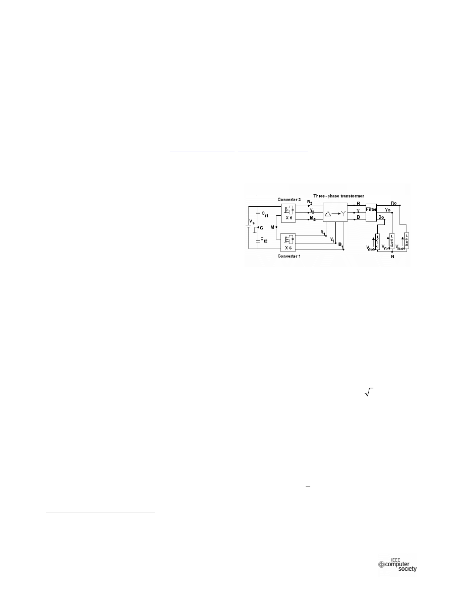
Figure 1. Block diagram of the multi-level
converter.
This paper describes the techniques used to design a
three-phase transformer which is a fundamental
component of a 1 kW multi-level inverter. The
transformer interconnects the outputs of two 6-pulse
inverters to produce 12-pulse voltage waveforms at the
output. The transformer transfers half of the throughput
power to the inverter output. The design and construction
of a 500 VA three-phase transformer for a 1kW inverter is
presented in this paper together with the practical issues
and considerations to build a transformer prototype.
1. Introduction
1
Inverters have been significant power converters for the
development of modern electric transportation systems;
however, high harmonic components generated by 6-
pulse inverters can modify the load behaviour. Several
strategies have been studied to obtain sinusoidal voltage
waveforms. For example, one method to diminish the
harmonic output content of standard 6-pulse inverters is
using PWM, multi-pulse and/or PWM multi-level
techniques.
Multi-pulse techniques were original developed for AC-
DC converters. These normally consist of arrangements
of 6-pulse converters interconnected in series or parallel
by three-phase transformers, reactors and/or capacitors at
the input or output of the converters.
A variant of multi-pulse inverter has been visualised
from the work reported in [1], which may be operated as
12, 24-pulse or even PWM multi-level inverter. To study
this variant of multi-pulse inverter and build a preliminary
prototype, a three-phase transformer design is required.
This paper presents the design and construction of the
three-phase transformer of the converter shown in Fig. 1,
which is part of a new generation of power inverters. The
This work was financially supported by the National Council of
Science and Technology (CONACyT), under the repatriation project
number 75648, and the National Polytechnic Institute (IPN) of Mexico,
under the project number SIP-20082849.
techniques used to design and select the transformer
components are described together with the design results
obtained to build a 500 VA transformer for a 1kW
converter.
1. Multi-level converter description
The 12-pulse inverter shown in Fig. 1, which is
composed of a DC rail, two capacitors connected in series
to filter the supply current and two 6-pulse three-phase
converters connected in series. The converters outputs are
connected to a delta-star transformer of 3 :1 turns-ratio,
and the star winding terminals are passed through a filter
stage before the load connection.
The transistors of each converter are operated in such a
way that the voltage waveforms v
R1G
, v
Y1G
, v
B1G
, v
R2G
and
v
B2G
are like those shown in Fig. 2, where v
R1G
, v
Y1G
and
v
B1G
are the outputs of converter 1 and, v
R2G
and v
B2G
are
the outputs of converter 2. v
R1N
is obtained subtracting the
common mode voltage of the converter, such that:
1
1
1
1
2
3
2
R N
R G
Y G
B
v
v
v
v
G
(1)
The voltage waveform at the transformer primary, v
Rprim
,
is obtained subtracting the voltages v
R2G
and v
B2G
at the
inputs of the delta windings, and therefore, the voltage at
the secondary winding, v
Rsec
,
is:
2009 International Conference on Electrical, Communications, and Computers
978-0-7695-3587-6/09 $25.00 © 2009 IEEE
DOI 10.1109/CONIELECOMP.2009.23
74
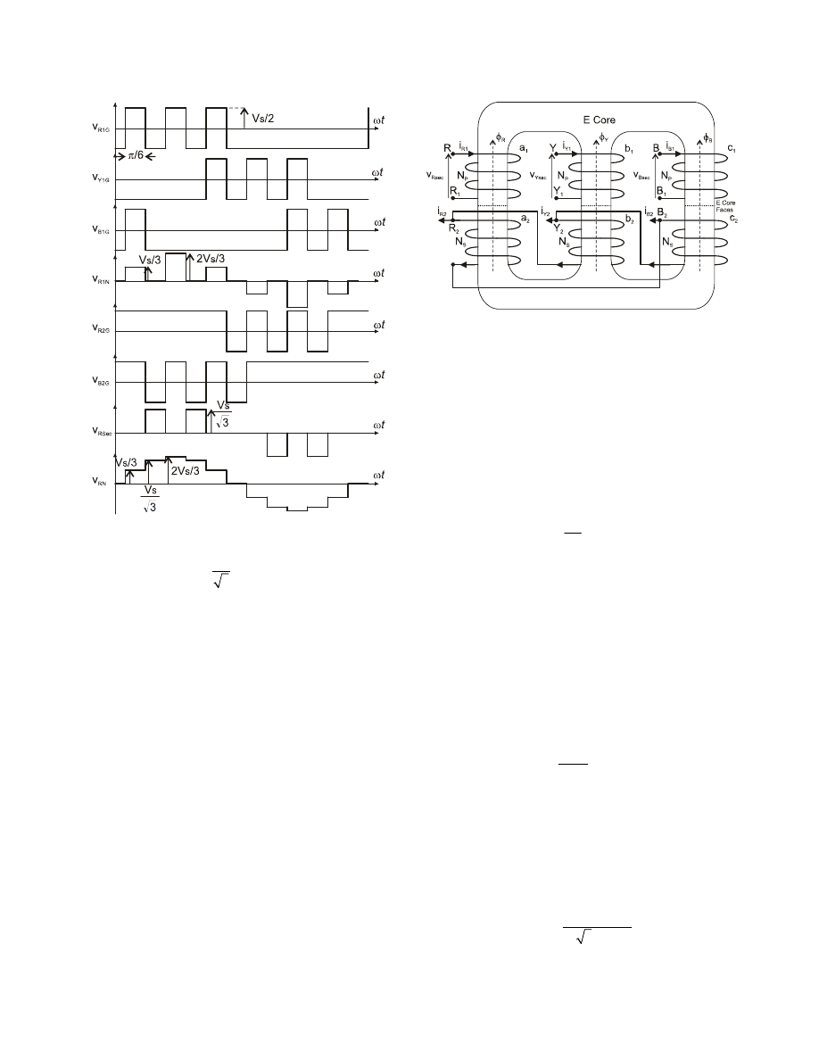
Figure 3. Mechanical diagram of the transformer.
sec
1
2
1
3
R
R N
B N
v
v
v
(2)
The 12-pulse converter reported in [2] produces
waveforms as those shown in Fig. 2 by the natural
switching of diodes. In contrast, the converter shown in
Fig. 1 produces the same waveforms but switching
transistors by an external control stage.
In Fig. 2 v
R1G
, v
Y1G
and v
B1G
have a negative semi-cycle
of magnitude V
S
/2; in contrast, v
R2G
and v
B2G
have a
positive semi-cycle and are phase-shifted by /6
respective to converter 1. The last waveform in Fig. 2
shows the phase voltage v
RN
, which is a 12-pulse wave
obtained by adding v
Rsec
and
v
R1N
. The duration of each
pulse of v
RN
is /6 due to the transistor switching period of
each converter.
The waveform v
Rsec
is useful to begin the design of the
transformer and calculate the maximum core flux density.
This is described in the following section.
3. Analysis of voltage and flux density
waveforms of the transformer
The analysis of the core flux is described assuming that
the three windings have equal core dimensions, as shown
in the mechanical diagram of Fig. 3, and the total flux in
the core produced by the three phases may be expressed
as:
Figure 2. Ideal waveforms of the converter.
0
I I I
R
Y
B
(3)
where the amplitudes and waves of
I
R
,
I
Y
, and
I
B
, are
equal, but phase-shitted by 120°. The magnetic flux
produced by the voltage impressed across the transformer
delta windings may be calculated using the Faraday’s law:
sec
1
I
³
R
R
s
v
dt
N
(4)
where N
s
is the number of turns of the secondary winding
and v
Rsec
is given in Eq. (2).
A flux core density, B
c
, can be assumed uniform
throughout the cross sectional area, A
c
, such that B
c
is
proportional to the flux density,
I
R
I
%
R
c
c
A
(5)
and hence, Eq. (4) and (5) may be used to calculate B
c
as
follows:
sec
1
c
R
s
c
B
v
N A
³
dt
(6)
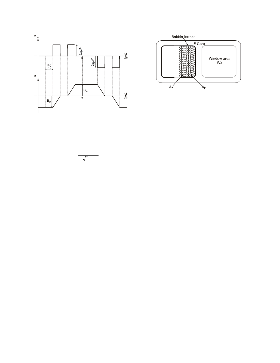
Fig. 4 shows the ideal waveform of B
c
obtained with Eq.
(6). This waveform has negative and positive slopes
produced by the respective negative and positive steps of
v
Rsec
, and the constant periods of B
c
are obtained when the
steps of v
Rsec
are zero. The amplitude of B
c
, B
pk
, can be
deduced geometrically from Eq. (6) and Fig. 4, such that:
12 3
s
pk
s
c
o
V
B
N A f
(7)
75
where f
o
is the fundamental frequency output and V
s
is the
supply voltage of the converter. The product N
s
A
c
of Eq.
(6) may be arranged in terms of Vs, f
o
and B
pk
:
12 3
s
s
c
pk
o
V
N A
B f
(8)
where N
s
A
c
should be constant to keep the flux density
below the saturation level of the core material under a
fixed ratio of Vs/f
0
. In this way, Eq. (8) is utilized to
obtain the number of turns for the primary and secondary
windings by choosing A
c
from the manufacturer core
datasheets.
4. Power loss evaluation
Part of the power that is transferred from the primary to
the secondary of the transformer is lost in form of heat
due to the core excitation, Eddy currents in the core and
copper resistance of the windings, [4]. These losses
depend on the voltage and currents applied to the
transformer windings. For example,
I
R
is produced from
v
Rsec
, Eqs. (5) and (6), and the core reluctance will
produce an electro-motive force (emf),
F=
I
R
R
c
, such that
the back-emf of the secondary windings is not equal to
that of the primary, since:
p
p p
s s
R
N i
N i
c
I
F
R (9)
where N
P
i
P
is the back-emf of the primary, and
I
R
R
c
is
the back-emf equivalent to the excitation and heat
disipated in the core; whereas a small resistance may be
considered for the windings since these are formed by
several meters of copper wire. The copper loss is
therefore an important issue for the transformer design,
since:
Figure 4. Ideal flux density waveform of the
transformer core.
Figure 5. Mechanical diagram of one winding
inside the E core.
2
1
cu
R
cu
P
i R
(10)
Several transformer design methods have been
developed based on Eq. (8) in order to choose the
appropriated core dimensions and wire diameters for the
windings. For example, a transformer design with
maximum efficiency is described in [3], which equates
the copper and core losses, P
cu
= P
c
; whilst in [4], an
optimization method to reduce the total losses, P
T
= P
c
+
P
cu
, is described assuming that the flux density amplitude
is below the saturation level.
Following the techniques given in [3] and [4], an
iterative method is described below to determine the
optimum number of turns for the windings and the core
size.
5. Determination of the optimum parameters
for the transformer components
A 3% Si, 97% Fe wound E core was selected since this
type of core can be built with thinner strip widths in
contrast to laminated cores. Furthermore, three-phase
transformers can be easily designed over wound E cores
because all the core limbs are equal in dimension;
however, wound E cores tend to be noisy due to the
contact of their half faces, [5], as shown in Fig. 3.
Firstly, the number of turns and wire gauge for primary
and secondary windings, W
gp
and W
gs
respectively, may
be determined considering the available core window area
W
A
, the current density J and losses of the copper, and the
bobbin former dimensions. In order to determine these
parameters, N
p
and N
s
may be first calculated using Eq.
(7), ranging the value of A
c
from the manufacturer core
datasheet and fixing B
pk
below the core flux density
saturation level, B
SAT
. Once obtained N
p
and N
s
, W
gp
and
W
gs
are selected in such a way that J should be lower than
5 A/mm
2
, [6], otherwise the temperature of the copper
wire will be high and the copper insulation could melt.
76
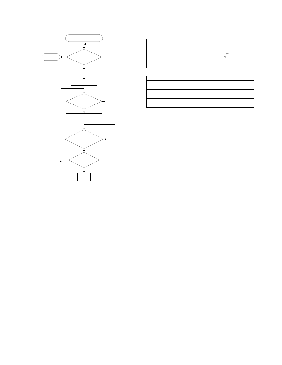
Table 1. Transformer ratings
Total Power
1 kW
Output Voltage
127 V
rms
±15%
Output Frequency
60 Hz
Turns-Ratio
3 :1
Phase Current (
I
R1
)
3.9321 A
Maximum Flux Density (
B
pk
)
1.5 T
Next Core Type
Transformer Design
Next Wire Gauge
NWPT ++
End of
Core Types?
End of
Wire Gauges?
2
2
5 A/mm
5 A/mm
p
s
J
J
2
A
P
s
W
A
A
? &
?
p
s
N
N
?
T
P
End
Yes
No
Yes
No
No
No
Yes
Yes
Figure 6. Flux diagram of the transformer design
strategy.
Table 2. Transformer winding parameters
Core Type
3Q6
N
p
278
N
s
481
NWPT
p
2
NWPT
s
1
Total layers per winding
12
Total power losses
34.27 W
One strategy to reduce J is by using multiple wires per
turn of the same gauge such that the total copper area is
increased; this is a solution to the current density
constraint of 5 A/mm
2
. The number of wires per turn for
the primary and secondary windings is referred as NWPT
p
and NWPT
s
respectively.
Secondly, the winding dimensions are estimated to
verify that these fit into W
A
using the calculated values of
N
p
, N
s
, NWPT
p
, NWPT
s
, W
gp
and W
gs
. The thickness of an
inter-layer thermal insulator and the dimensions of a
bobbin former are also considered in the calculation of the
winding dimension since these reduce the available
window area for the windings. This is shown in Fig. 5
where the bobbin former thickness and the primary and
secondary windings areas, A
p
and A
s
respectively, are
indicated. If the total winding area, A
T
= A
p
+ A
s
, is
higher than W
A
the wire gauge need to be selected again
until A
T
fits into W
A
. These areas are shown in the
mechanical diagram of Fig. 5.
Once the windings fit into the core, P
T
is estimated
calculating P
c
and P
cu
. P
c
is obtained from the
performance curves of the manufacturer core datasheets
for a fixed value of B
pk
, and P
cu
is calculated as follows:
sec
3
3
cu
prim
P
P
P
(11)
where P
prim
and P
sec
are the primary and secondary
winding copper losses which may be obtained using Eq.
(10).
Finally, the above procedure is iteratively repeated for a
core type range and different wire gauges, and is
illustrated in the block diagram shown in Fig. 6. In this
way, minimal values of P
T
are gathered from the results
and the core size and wire gauges are therefore selected.
6. Design Results
A three-phase transformer for the converter shown in
Fig. 1 was designed using a spreadsheet and the
description given above. The transformer ratings used for
this design are listed in Table 1.
The core size was ranged from 3Q1 to 3Q12 using the
Wiltan datasheet specification for wound E cores, [7]. In
the same way, the wire gauge was ranged from 15 to 27
using the American Wire Gauge standard. The
spreadsheet showed that the optimum core size were
between 3Q6 and 3Q7; whereas the appropriate wire
gauges were between 19 and 25. Minimal total power
losses were obtained in these ranges assuming that J and
the winding size were below the maximum values.
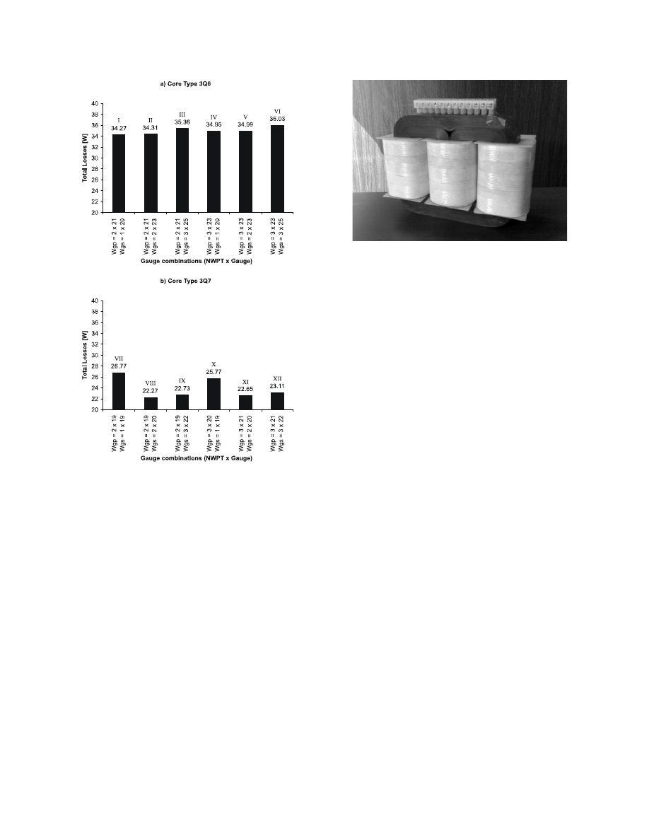
Figs. 7(a) and 7(b) show in bar charts the power losses
obtained in the spreadsheet for the cores 3Q6 and 3Q7
respectively, with combinations of W
gp
, W
gs
, NWPT
P
and
NWPT
s
. Fig. 7(a) shows that minimal values of P
T
are
obtained for combinations (I) and (II), 34.27 W and 34.31
W respectively; whilst in Fig. 7(b) combinations (VIII)
and (XI) produce the lowest power losses, 22.27 W and
22.65 W respectively.
The figures show that the lowest power loss is obtained
using a 3Q7 core with combination (VIII); however, the
transformer dimensions for this result are greater than the
results obtained with the 3Q6 core and, therefore, a 3Q6
core with combination (I) was chosen to build the
77
transformer. Table 2 shows the winding construction
parameters with a 3Q6 core and combination (I).
The windings were built using an academic winding
machine. NOMEX paper, [8], was used as interlayer
thermal insulator and a small gap between the windings
was considered for cooling purposes along their
construction. Fig. 8 shows a photograph of the
constructed transformer.
7. Conclusion
A three-phase transformer design for a new generation
multi-pulse inverter was presented in this paper. The
design was focused to obtain minimal power losses and
was performed using an iterative process of component
selection.
The transformer core and winding characteristics were
obtained from several combinations of core and wire
gauges that produced minimal power losses. In this
fashion, an optimum transformer design was obtained
with low power losses and reduced dimensions.
Figure 7. Total losses for different wire gauge
combinations: (a) 3Q6 core; (b) 3Q7 core.
Figure 8. Constructed Transformer.
Future work could consider the use of other core and
wire materials in order to improve the transformer size
and weight with low power losses.
8. Acknowledgments
The authors are grateful to National Polytechnic Institute
of México (IPN) and the National Council of Science and
Technology (CONACyT) for their encouragement and
support to build the prototype.
9. References
[1] Ismael Araujo-Vargas, Andrew J. Forsyth, “High-
Performance Multi-pulse with single-transistor active
injection”, IEEE transactions on Power Electronics,
Vol. 23-3, 2008, pp. 1299-1308.
[2] F.J. Chivite – Zabalza, A.J. Forsyth, D.R. Trainer, “A
simple, passive 24 – pulse ac-dc converter with in
herent load balancing”, IEEE transactions on Power
Electronics, Vol. 21-2, 2006, pp. 430-439.
[3] T. McLyman Colonel WM., “Transformer and
inductor design handbook”, third edition, California,
U.S.A., 2004.
[4] Erickson Robert W., D. Maksimovic, “Fundamentals
of power electronics”, second edition, Colorado,
2001, ISBN 0-7923-7270-0.
[5] William M. Flanagan, “Handbook of transformer
design and applications”, second edition, U.S.A.,
1993, ISBN 0-07-021291-0.
[6] N. Mohan, T. M. Undeland, W. P. Robbins, “Power
electronics converters, applications, and design”,
second edition, U.S.A., 1995, ISBN 0-471-58408-8.
[7] http://www.wiltan.co.uk/client_files/default/wiltan_g
uide.pdf, “Silicon steel wound E&C cores”, Wiltan
Telmag magnetic components.
[8] http://www.pleo.com/dupund/nomex.htm, 0.13mm
Nomex Around paper for Thermal Insulation.
78
Wyszukiwarka
Podobne podstrony:
[architecture ebook] Design And Construction Of Japanese Gardens
Properties and Structures of Three phase PWM AC Power Controllers
A Composite Pwm Method Of Three Phase Voltage Source Inverter For High Power Applications
Design and implementation of Psychoacoustics Equalizer for Infotainment
The Discrete Time Control of a Three Phase 4 Wire PWM Inverter with Variable DC Link Voltage and Bat
The Discrete Time Control of a Three Phase 4 Wire PWM Inverter with Variable DC Link Voltage and Bat
Optimal Control of Three Phase PWM Inverter for UPS Systems
Sexual behavior and the non construction of sexual identity Implications for the analysis of men who
A Composite Pwm Method Of Three Phase Voltage Source Inverter For High Power Applications
Sonpar, Pazzaglia The Paradox and Constraints of Legitimacy
Development Of A Single Phase Inverter For Small Wind Turbine
DESIGN AND DEVELOPMENT OF MICRO TURBINE
Energy performance and efficiency of two sugar crops for the biofuel
Command and Control of Special Operations Forces for 21st Century Contingency Operations
Design and Performance of the OpenBSD Statefull Packet Filter Slides
Design and manufacturing of plastic
Ship Design and Construction Volume II Contents
więcej podobnych podstron