Autodiagnos Ltd
Hopton Estate, London Road, Devizes, SN10 2EU
Tel: 0870 949 3799 Fax: 01380 732001 Email: info@autodiagnos.com
www.autodiagnos.com
Autodiagnos Limited is registered in England and Wales at Hopton Industrial Estate, Devizes,
Wiltshire, SN10 2EU. Company No. 3062855
Audi, Seat, Skoda and Volkswagen
Audi, Seat, Skoda and Volkswagen
Engine Codes
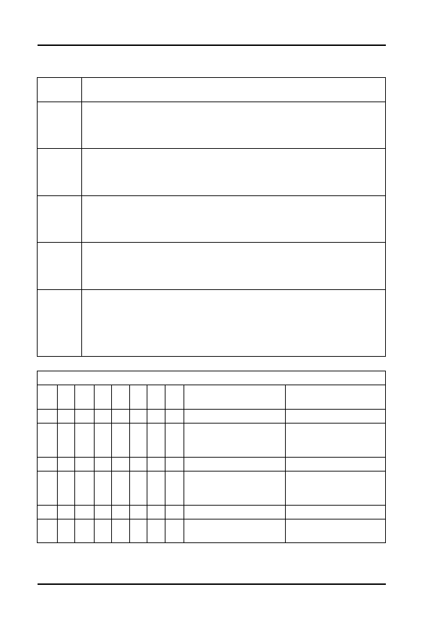
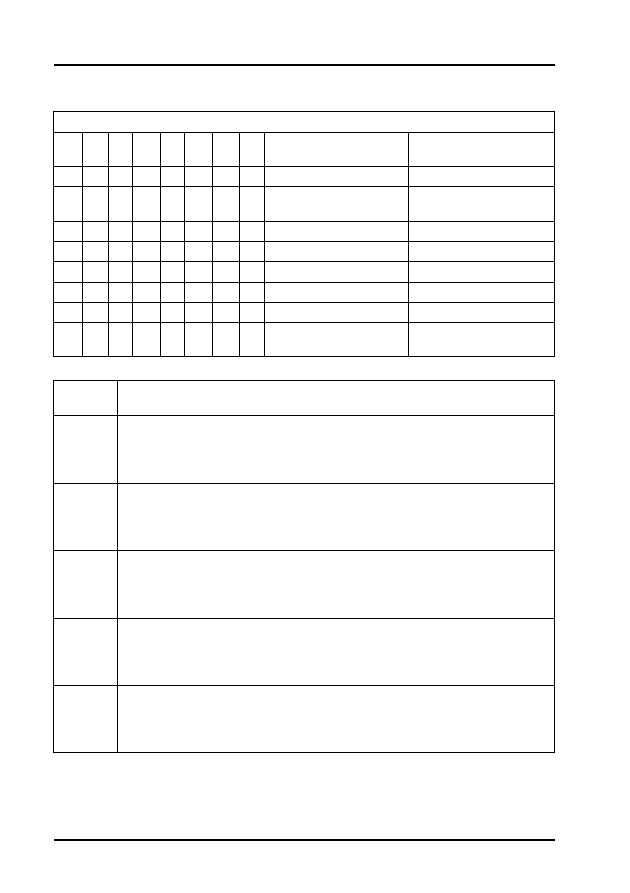
Engine Code: ADX, AEA, ABD, ABU and AEV
Display
Group
Description
1
1. Engine speed.
2. Coolant temperature.
3. Lambda value.
4. Operating condition (see Table 1 for the relevance of these figures).
2
1. Engine speed.
2. Injection period.
3. Battery voltage.
4. Intake air temperature.
3
1. Engine speed.
2. Engine load signal.
3. Throttle valve angle. Calculated figure, dependent on throttle valve
potentiometer.
4. Ignition timing value. Calculated figure, dependent on the ignition timing
adjustment (this value must not be used to check or adjust ignition
timing).
4
1. Engine speed.
2. Engine load signal.
3. Road speed (for engine code ABD > 9.94, the speed will not be shown).
4. Operating condition (see Table 1 for the relevance of these figures).
5
1. Engine speed.
2. Duty cycle (of activated charcoal filter solenoid valve 1).
3. Lambda correction factor.
4. Mixture correction factor.
6
1. Engine speed.
2. Duty cycle (of activated charcoal filter solenoid valve 1).
3. Lambda correction factor.
4. Mixture correction factor.

Audi, Seat, Skoda and Volkswagen
2
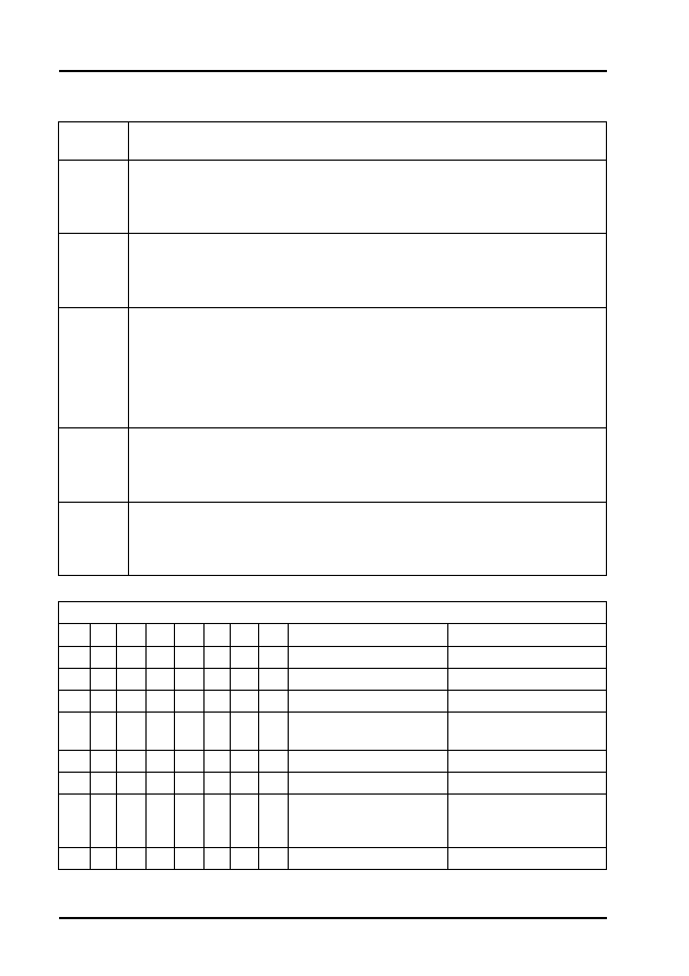
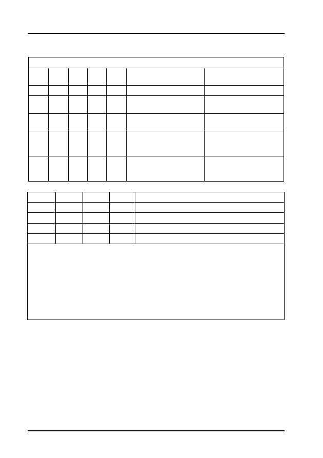
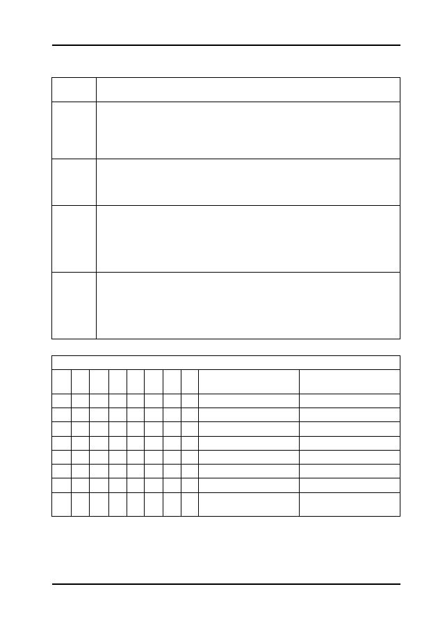
Table 1 - Operating Conditions (AEA only)
7
1. Engine speed.
2. Lambda probe voltage.
3. Lambda correction factor.
4. Operating condition (see Table 1 for the relevance of the figures).
8
1. Engine speed.
2. Load.
3. Knock control number 1 cylinder (ignition retardation).
4. Knock control number 2 cylinder (ignition retardation).
9
1. Engine speed.
2. Load.
3. Knock control number 3 cylinder.
4. Knock control number 4 cylinder.
10
1. Engine speed.
2. Load.
3. Integral knock number 1 cylinder.
4. Integral knock number 2 cylinder.
11
1. Engine speed.
2. Load.
3. Integral knock number 3 cylinder.
4. Integral knock number 4 cylinder.
Relevant when '1' is displayed in the 8-digit block
X
X
X
X
X
X
X
X
Display Group
1
Display Group
4
Display Group 7
1
No. 1 cylinder
recognised
-
-
1
Idling switch
closed
-
Activated
charcoal filter
system solenoid
valve 1 active
1
AT recognised -
Lambda control
active
1
A/C
compressor
switched on
(`1' must not
be displayed)
Acceleration
or full load
enrichment
Acceleration or
full load
enrichment
1
A/C switched
on ('1' must
not be
displayed)
Full load
recognised
Full load
recognised
1
Speed boost
gear engaged
Part load
recognised
Part load
recognised

Audi, Seat, Skoda and Volkswagen
3
1
Torque
reduction
(display must
always show
'1')
Idling switch
closed
Idling switch
closed
1
Gear engaged
(if '1' is
displayed)
Overrun
cut-off active
Overrun cut-off
active
Audi, Seat, Skoda and Volkswagen
4
Engine Code: AAM, ABS and ADZ
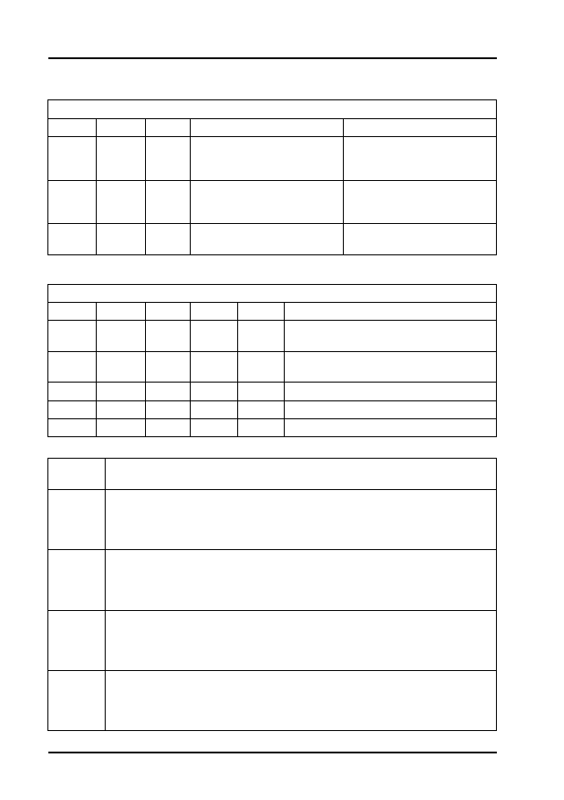
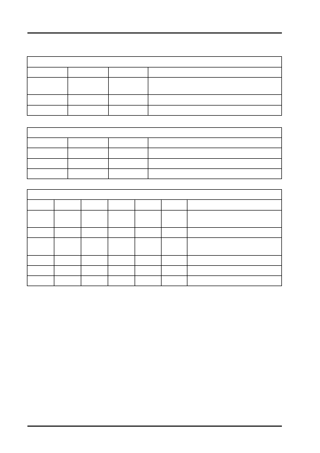
Table 2 - Operating Conditions
Display
Group
Description
1
1. Engine speed.
2. Coolant temperature.
3. Lambda correction factor.
4. Operating condition (see Table 2 for the relevance of these figures).
2
1. Engine speed.
2. Injection period.
3. Battery voltage.
4. Intake air temperature.
3
1. Engine speed.
2. Engine load signal.
3. Throttle valve angle. Calculated figure, dependent on throttle valve
potentiometer.
4. Ignition timing value. Calculated figure, dependent on the ignition timing
adjustment (this value must not be used to check or adjust ignition
timing).
4
1. Engine speed.
2. Engine load signal.
3. Road speed (0 to 7, with 4 as a centred value).
4. Operating condition (see Table 1 for the relevance of these figures).
5
1. Engine speed.
2. Duty cycle (of activated charcoal filter solenoid valve 1).
3. Lambda correction factor.
4. Mixture correction factor.
Relevant when '1' is displayed in the 8-digit block
X
X
X
X
X
X
X
X
Display Group 1
Display Group 4
1
-
-
1
Idling switch closed
-
1
-
-
1
A/C compressor
switched on
Acceleration or full load
enrichment
1
A/C switched on
Full load recognised
1
-
Part load recognised
1
Torque reduction
(display must always
show '1')
Idling switch closed
1
Driving stage engaged
Overrun cut-off active

Audi, Seat, Skoda and Volkswagen
5
Engine Code: AEK
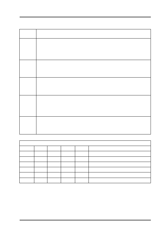
Table 3 - Engine Code AEK
Display
Group
Description
1
1. Engine speed.
2. Coolant temperature.
3. Lambda value.
4. Ignition timing.
2
1. Engine speed.
2. Injection period.
3. Battery voltage.
4. Not relevant.
3
1. Engine speed.
2. Engine load signal.
3. Throttle valve angle.
4. Intake manifold temperature.
4
1. Engine speed.
2. Engine load signal.
3. Road speed signal.
4. Operating condition (see Table 3 for the relevance of these figures).
5
1. Engine speed.
2. Learned idling stabilisation value.
3. Idling stabilisation valve duty cycle.
4. Adjustment requirements (see Table 3 for the relevance of these
figures).
6
1. Lambda factor.
2. Learned idling adaption value (specification range not currently
available).
3. Learned part load adaption value (specification range not currently
available).
4. Learned full load adaption value (specification range not currently
available).
Relevant when '1' is displayed in the 5-digit block
X
X
X
X
X
Display Group 4
Display Group 5
1
Overrun
Not relevant
1
Idling
Signal from AT
1
Part load
N/A
1
Full load
A/C stand-by
1
Acceleration
A/C compressor
switched on

Audi, Seat, Skoda and Volkswagen
6
Engine Code: ABF (Digifant 3.0)
Display
Group
Description
1
1. Coolant temperature.
2. Engine speed.
3. Lambda probe voltage.
4. Injection period
2
1. Coolant temperature.
2. Engine speed.
3. Throttle valve angle. Calculated figure, (dependent on throttle valve
potentiometer).
4. Injection period.
3
1. Coolant temperature.
2. Engine speed.
3. Intake air temperature.
4. Battery voltage.
4
1. Coolant temperature.
2. Engine speed.
3. Ignition timing. Calculated figure (this value must not be used to check
or adjust ignition timing).
4. Engine load.
5
1. Coolant temperature.
2. Engine speed.
3. Throttle valve angle. Calculated figure, (dependent on throttle valve
potentiometer).
4. Battery voltage.

Audi, Seat, Skoda and Volkswagen
7
Engine Code: ABF (Digifant 3.2)
NOTE: Always observe the values in lines 1 and 2 of this display group together.
If a 0 is displayed in line 1, line 2 must show a value between 0 and 70.
If 225 is displayed in line 1, line 2 must show a value between 144 and 255.
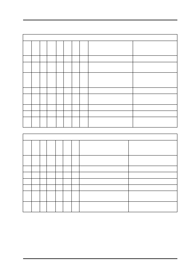
Table 4 - Operating Conditions
Display
Group
Description
1
1. Engine speed
2. Coolant temperature.
3. Lambda probe voltage.
4. Adjustment conditions (see Table 4 for the relevance of these figures).
2
1. Engine speed.
2. Injection period.
3. Battery voltage.
4. Intake air temperature.
3
1. Engine speed.
2. Engine load.
3. Throttle valve angle. Calculated figure, (dependent on throttle valve
potentiometer).
4. Intake air temperature.
4
1. Engine speed.
2. Engine load.
3. Not relevant.
4. Operating condition (see Table 4 for the relevance of these figures).
5
1. Engine speed.
2. Engine load.
3. N/A
4. Operating condition (see Table 4 for the relevance of these figures).
6
1. Lambda integration value (see note below).
2. Lambda integration value (see note below).
3. Learning value for idling stabilisation.
4. Intake air temperature.
X
X
X
X
X
X
X
X
Display groups 1, 4 & 5 line 4
1
Fault stored in memory
1
Not assigned
1
A/C compressor switched on
1
Idling switch open
1
Fault in lambda control
1
Throttle valve closed
1
Engine speed above 2500 rpm
1
Coolant temperature below 80°C

Audi, Seat, Skoda and Volkswagen
8
Engine Code: 2E
Engine Code: 1Z
Display
Group
Description
1
1. Coolant temperature.
2. Engine speed.
3. Lambda probe voltage.
4. Injection time.
2
1. Coolant temperature.
2. Engine speed.
3. Throttle angle.
4. Engine load signal.
3
1. Coolant temperature.
2. Engine speed.
3. Air intake temperature.
4. Battery voltage.
4
1. Coolant temperature.
2. Engine speed.
3. Calculated ignition point.
4. Engine load signal.
5
1. Coolant temperature.
2. Engine speed.
3. Throttle angle.
4. Battery voltage.
Display
Group
Description
1
1. Engine speed.
2. Quantity injected.
3. Voltage supplied (specified).
4. Coolant temperature
2
1. Engine speed
2. Accelerator pedal position
3. Operating condition (see Table 5 for the relevance of the figures in line
3).
4. Coolant temperature
3
1. Engine speed.
2. Mass of air drawn in (specified).
3. Mass of air drawn in (Actual. The measurement requires that the EGR
system be switched off after a period of approximately 10 minutes at idle
speed, requiring a burst of throttle or an engine restart to switch it back
on).
4. EGR valve duty cycle (specified).

Audi, Seat, Skoda and Volkswagen
9
4
1. Engine speed.
2. Commencement of injection (specified).
3. Commencement of injection (actual).
4. Duty cycle commencement of injection valve.
5
1. Engine speed.
2. Start quantity
3. Commencement of injection (specified).
4. Coolant temperature
6
1. Vehicle speed.
2. Brake pedal monitor (see Table 5 for the relevance of the figures in line
2).
3. Cruise control system (see separate cruise control table F for the
relevance of the figures in line 3).
4. Cruise control system (vehicles fitted with cruise control system display
0, vehicles without cruise control system display 255).
7
1. Fuel temperature.
2. No display.
3. Intake manifold temperature.
4. Coolant temperature.
8
1. Engine speed.
2. Quantity injected (driver's requirement - pedal position
3. Injection quantity limitation value (from torque map).
4. Injection quantity limitation value (from opacity map).
9
1. Engine speed.
2. Quantity injected (cruise control system active).
3. Injection quantity limitation (Cruise control active).
4. Voltage supplied (from opacity map).
10
1. Mass of air drawn in (actual).
2. Atmospheric pressure (ambient)
3. Intake manifold pressure (charge pressure).
4. Accelerator pedal position.
11
1. Engine speed.
2. Charge pressure (specified).
3. Charge pressure (actual).
4. Duty cycle from charge pressure limitation valve.
12
1. Not relevant.
2. Glow period.
3. Voltage supply from control unit.
4. Coolant temperature.
13
1. Quantity injected (deviation - No. 4 cylinder to No. 3 cylinder).
2. Quantity injected (deviation - No. 2 cylinder to No. 3 cylinder).
3. Quantity injected (deviation - No. 1 cylinder to No. 3 cylinder).
4. No display.
Audi, Seat, Skoda and Volkswagen
10
Table 5
Table 6
Engine Code: ABV
Relevance when '1' is displayed in the three digit block
X
X
X
Display Group 2 - Line 3
Display Group 6 - Line 2
1
Idling speed boost when air
conditioning system is
switched on
Clutch pedal switch open
(brake pedal open)
1
Idling speed switch closed
(accelerator pedal position
below 17%)
Brake pedal switch open
(brake pedal operated)
1
Conditioner compressor on
Brake pedal switch open
(brake pedal operated)
Relevance when '1' is displayed in the 5 digit block
X
X
X
X
X
Display Group 6 - LIne 3
1
Clutch pedal switch open (clutch pedal
operated)
1
Brake light switch closed (brake pedal
operated)
1
Speed accepted
1
Speed accepted
1
Cruise control system on
Display
Group
Description
1
1. Engine speed.
2. Engine temperature.
3. Lambda factor.
4. Ignition angle.
2
1. Engine speed.
2. Injection time.
3. System voltage.
4. EGR temperature (if acceptable).
3
1. Engine speed.
2. Engine load.
3. Throttle valve angle.
4. Intake manifold temperature.
4
1. Engine speed.
2. Engine load.
3. Road speed.
4. Operating status (see Table 7 for the relevance of the figures in line 4).

Audi, Seat, Skoda and Volkswagen
11
Table 7
5
1. Engine speed.
2. Idling speed stabilisation valve.
3. Duty cycle.
4. Operating status (see Table 7 for the relevance of the figures in line 4).
6
1. Lambda factor.
2. Lambda adaption (Idle).
3. Lambda adaption (part load).
4. Lambda adaption (full throttle).
Relevance when '1' is displayed in the 5 digit block
X
X
X
X
X
Operating status
Display group 4 (5
block numeric
group - Operating
status may also be
shown, for
example
acceleration from
part load, as
10100).
Operating status.
Display group 5 (4
block numeric
group - Operating
status may be also
shown, for
example Air con.
compressor and
air con. on, as 11
Display Group 1).
1
Acceleration
enrichment
Not relevant
1
Full throttle
Air conditioning
compressor on
1
Part load
Air conditioning on
1
Idling speed
Gearbox
intervention (auto
gearbox)
1
Overrun cut-off
Driving position
(auto gearbox
only)
Operating statuses
not OK, interrogate
fault memory again
Not relevant

Audi, Seat, Skoda and Volkswagen
12
Engine Code: ADY and AGG
Display
Group
Description
1
1. Engine speed.
2. Coolant temperature.
3. Lambda probe voltage.
4. Adjustment condition (see Table 8 for the relevance of the figures in line
4).
2
1. Engine speed.
2. Injection period.
3. Battery voltage.
4. Intake air temperature.
3
1. Engine speed.
2. Engine load.
3. Throttle valve angle.
4. Duty cycle (off throttle valve positioner).
4
1. Engine speed.
2. Engine load.
3. Road speed.
4. Engine operating condition (see Table 8 for the relevance of the figures
in line 4).
5
1. Engine speed.
2. Duty cycle (for activated charcoal filter).
3. Consumption signal.
4. Operating condition (of Lambda control (see Table 9 for the relevance of
the figures in line 4).
6
1. Additive learning value (for Lambda control at idling).
2. Multiplicative learning value (for Lambda control at part/full load range).
3. Multiplicative learning value (for throttle valve positioner duty cycle).
4. Multiplicative learning value (for throttle valve positioner duty cycle with
auto gearbox).
7
1. Co-ordination (of Hall sender to engine speed sensor).
2. Co-ordination (of Hall sender to engine speed sensor).
3. Altitude correction value
4. Operating condition (of throttle valve positioner. Refer to Table 8 for the
relevance of the figures in line 4).
Audi, Seat, Skoda and Volkswagen
13
Table 8
Table 9
Relevance when '1' is displayed in the 8 digit block
X
X
X
X
X
X
X
X
Adjustment Conditions
Display Group 1
Engine Operating
Conditions Display
Group 4
1
Not relevant
Overrun
1
Signal from automatic
gearbox
Idling
1
Air conditioner
compressor switched
on
Part load
1
Idling switch on
Full load
1
Fault in the Lambda
control
Not relevant
1
Throttle valve open
Not relevant
1
Engine running
Not relevant
1
Coolant temperature
below 80°C
Not relevant
Relevance when 1 is displayed in the 8 digit block
X
X
X X
X
X
X
Lambda Control
Operating condition -
Display Group 5
Throttle Valve Control
Operating Condition -
Display Group 7
1
Coding for synchro
Mechanical emergency
running
1
Not relevant
Not relevant
1
Not relevant
Adaption necessary
1
Lambda control at limit
Adaption necessary
1
Diagnostic fault
Not relevant
1
Lambda probe
operationally ready
Adaption terminated
(battery voltage too low)
1
Rich mixture (0= lean
mixture)
Idle switch open

Audi, Seat, Skoda and Volkswagen
14
Engine Code: ABK
Display
Group
Description
1
1. Engine speed (idling).
2. Coolant temperature.
3. Lambda probe voltage (fluctuates).
4. Setting condition (see Table 10 for the relevance of the figures in line 4).
2
1. Engine speed.
2. Injection time (computed value between 1.5 and 3.5 ms at idle speed).
3. Digifant control unit voltage supply.
4. Intake air temperature
3
1. Engine speed.
2. Engine loading (idling).
3. Throttle valve angle (0 to 2.0% full load greater than 75%).
4. Duty cycle (off idling speed stabilisation valve (idling)).
4
1. Engine speed.
2. Engine load.
3. Road speed signal (stationary = 255, driving = 0).
4. Engine load operating state (see Table 11 for the relevance of the
figures in line 4).
5
1. Engine speed.
2. Duty cycle - Of activated charcoal filter solenoid valve -N80 (Valve fully
open = 100% valve closed =0%). This is closed when engine is idling
and so long as Lambda control is not active.
3. Consumption signal - On board computer calculation. The signal can
checked by observing it with the engine idling, then 'blipping' the throttle
to raise the engine speed and releasing immediately to bring the
overrun fuel cut-off function in. At idle the reading should indicate 1,
should then increase, drop to 0 then return to 1 again.
4. Operating condition (of Lambda control (see Table 9 for the relevance of
the figures in line 4)

Audi, Seat, Skoda and Volkswagen
15
Table 10 - Setting Conditions Table
Table 11 - Engine Load Operating State Table
Relevance when '1' is displayed in the 8 digit block. These setting conditions are met
only when 8 zeros are indicated.
X
X
X
X
X
X
X
X
Display Group 1 - Line 4
1
Not relevant
1
Ignition angle retardation during gearshift active
(auto only)
1
AC compressor not switched off (switched
automatically)
1
Idling switch not closed
1
Lambda control switched off
1
Throttle valve open
1
Engine speed within valid range
1
Engine temperature less than 80°C
Relevance when '1' is displayed in the 8 digit block. Read-out = 0, operating state not
achieved. Read-out = 1, operating state achieved
X
X
X
X
X
X
X
Display Group 4 - line 4
1
Overrun fuel cut-off (10000000)
1
Idling (01000000)
1
Part load (0010000)
1
Full Load (00010000)
1
Not relevant
1
Not relevant
1
Not relevant
Audi, Seat, Skoda and Volkswagen
16
Engine Code: AAE
Table 12 - Setting Conditions Table
Display
Group
Description
1
1. Engine speed.
2. Coolant temperature.
3. Lambda control value.
4. Operating state (see Table 12 for the relevance of the figures in line 4).
2
1. Engine speed.
2. Injection time (computed value between 1.5 and 3.5 ms at idle speed).
3. Battery voltage
4. Intake air temperature
3
1. Engine speed.
2. Engine load.
3. Throttle valve angle (idling 0 to 2.0%, full load greater than 75%).
4. ignition angle.
4
1. Engine speed.
2. Engine load.
3. Road speed signal (Stationary = 255, driving = 0).
4. Operating state (see Table 12 for the relevance of the figures in line 4).
5
1. Engine speed.
2. Duty cycle - Operating states may be combined on the display,
dependent on the status of the vehicle equipment active at that
particular time.
3. Lambda control valve.
4. Mixture correction factor.
Relevance when '1' or '0' is displayed in the 8 digit block
X
X
X
X
X
X
X
X
Operating State -
Display Group 1
Operating state Display
4
1
Idling contact closed
-
1
AC compressor on
Acceleration
enrichment/lean
mixture on deceleration
1
Air conditioner on
Full load
0
Torque reduction
(gearshift intervention
in auto gearbox)
-
1
-
Idling contact closed
1
Driving stage
(automatic gearbox)
Overrun cut-off

Audi, Seat, Skoda and Volkswagen
17
Engine Code: ABC
Display
Group
Description
1
1. Engine speed.
2. Intake manifold pressure (100% = 1022 hPa, 32% = 327 hPa).
3. Not relevant
4. Idling stabilisation position (18 to 75 steps at idle).
2
1. Throttle valve angle.
2. Not relevant.
3. Coolant temperature.
4. Intake air temperature.
3
1. Lambda learning factor (cylinders 1 to 3, 0.84 to 1.12).
2. Not relevant.
3. Lambda control factor (cylinders 1 to 3, 0.84 to 1.2).
4. Not relevant.
4
1. Not relevant.
2. Not relevant.
3. Lambda control factor (cylinders 1 to 3).
4. Not relevant.
5
1. Engine speed.
2. Knock control depth (base read-out = 60°).
3. Not relevant.
4. Coolant temperature.
6
1. Idling stabilisation position.
2. Idling stabilisation learning value.
3. Idling stabilisation disturbance influence.
4. Not relevant.
7
1. Idling stabilisation position.
2. Coolant temperature.
3. Lambda learning factor (cylinders 1 to 3).
4. Not relevant.
8
1. Idling stabilisation position.
2. Coolant temperature.
3. Lambda learning factor (cylinders 1 to 3).
4. Not relevant.
9
1. Coolant temperature.
2. Idling switch position (0 = open, 1 = closed).
3. Not relevant.
4. Engine speed.
10
1. Coolant temperature.
2. Idling switch position (0= open, 1 = closed).
3. Lambda learning factor (cylinders 1 to 3).
4. Not relevant.

Audi, Seat, Skoda and Volkswagen
18
Engine Code: AAH (and ABC for A4 models '95 on)
Display
Group
Description
1
1. Coolant temperature (85 to 105°C up to 05/94, 85 to 110°C 06/94 on).
2. Air mass meter output voltage (1.45 to 1.58V, or 1.47 to 1.62V,
dependent on valve-gear type).
3. Altitude read-out (0 to 0.025V up to 05/94, or 0 to 255).
4. Voltage supply to ECU (battery voltage) - 12.0 to 14.0V.
2
1. Throttle valve potentiometer voltage (voltage 0.25 to 4.75V - idle speed
through to full load).
2. Throttle valve potentiometer voltage (voltage 0.25 to 1.275V - idle speed
at lower part of load range).
3. Throttle valve potentiometer voltage (programmed value (0.25 to
0.50V).
4. Mechanical idle switch. (0 = open, 1 = closed).
3
1. Engine speed - Idle speed 700 to 800 rpm up to 05/94 then 650 to 750
or 700 to 800 rpm from 06/94 on dependent upon valve-gear type fitted.
2. Engine load - 15 to 32% up to 05/94, then 15 to 32% or 15 to 35% from
06/94 on dependent upon valve-gear type fitted
3. Throttle valve angle - With ignition on only 0% (idle) or greater than 95%
(full load).
4. Vehicle speed.
4
1. Idling speed controller - At idle. Range between -2 and 2.
2. Idling speed stabilisation value - Automatic gearbox with 'N' or 'P'
selected, manual gearbox in neutral. Manual = -16 to 14, auto = -20 to
10
3. Idling speed stabilisation value - Automatic gearbox in 'D', 1, 2, 3, or 'R',
Manual always = 0, auto. = -20 to 10.
4. Gearbox input when engine idling 0 = off, and 1 = on. Refer to Table 13.
5
1. Lambda programmed value - -25 to 25% at idling speed (bank 1).
2. Lambda programmed value - -19 to 19% (vehicles to 05/94), -25 to 25%
(vehicles 06/94 on), at part load 1 (bank 1).
3. Lambda programmed value - -19 to 19% (vehicles to 05/94), -25 to 25%
(vehicles 06/94 on), at part load 2 (bank 1).
4. Lambda programmed value - -19 to 19% (vehicles to 05/94), -25 to 25%
(vehicles 06/94 on), at part load 3 (bank 1).
6
1. Lambda programmed value - -25 to 25% at idling speed (bank 2).
2. Lambda programmed value - -19 to 19% (vehicles to 05/94), -25 to 25%
(vehicles 06/94 on), at part load 1(bank 2).
3. Lambda programmed value - -19 to 19% (vehicles to 05/94), -25 to 25%
(vehicles 06/94 on), at part load 2 (bank 2).
4. Lambda programmed value - -19 to 19% (vehicles to 05/94), -25 to 25%
(vehicles 06/94 on), at part load 3 (bank 2).

Audi, Seat, Skoda and Volkswagen
19
7
1. Lambda control (bank 1) - -6.0 to 6.0%.
2. Lambda programme range display (see Table 14 for the relevance of
the figures in line 2).
3. Lambda programme demand diagnosis (see Table 15 for the relevance
of the figures in line 3).
4. Lambda programme demand display (see Table 15 for the relevance of
the figures in line 4). Not relevant.
8
1. Lambda control (bank 2) - -6.0 to 6.0%.
2. Lambda programme range display (see Table 14 for the relevance of
the figures in line 2).
3. Lambda programme demand diagnosis (see Table 15 for the relevance
of the figures in line 3).
4. Lambda programme demand display (see Table 15 for the relevance of
the figures in line 4). Not relevant.
9
1. Lambda control (bank 1).
2. Lambda control (bank 2).
3. Charcoal filter valve duty cycle.
4. Throttle valve angle (at idling speed = 0, at full load = greater than 95%).
10
1. Assigned Lambda value (the difference between this reading and the
field 2 below must always be < 8%).
2. Assigned Lambda value (the difference between this reading and the
field 1 above must always be < 8%).
3. Lambda probe 1 voltage (bank 1) - Reading must fluctuate, occasionally
going beyond 0.3 to 0.6V range.
4. Lambda probe 1 voltage (bank 2) - Reading must fluctuate, occasionally
going beyond 0.3 to 0.6V range.
11
1. Ignition timing - without knock control and without digital idling speed
stabilisation. - (with idling switch open - engine speed raised).
2. Ignition timing - with knock control and with digital idling speed
stabilisation. - (average of all four cylinders).
3. Ignition timing intervention (for digital idling speed stabilisation).
4. Idling switch function (0 = open, 1 = closed).
12
1. Momentary engine speed.
2. Engine load.
3. Ignition timing map switch-over - selected by the knock control function
under a variety of conditions including poor fuel quality or abnormal
engine noises (loose ancillaries or other engine damage).
4. Ignition timing retardation of knock control - active from a engine load of
greater than 40% - average of all cylinders.
13
1. Ignition timing map switch-over - selected by the knock control function
under a variety of conditions including poor fuel quality or abnormal
engine noises (loose ancillaries or other engine damage).
2. Ignition timing retard of knock control (cylinder 1).
3. Ignition timing retard of knock control (cylinder 2).
4. Ignition timing retard of knock control (cylinder 3).

Audi, Seat, Skoda and Volkswagen
20
14
1. Ignition timing map switch-over - selected by the knock control function
under a variety of conditions including poor fuel quality or abnormal
engine noises (loose ancillaries or other engine damage).
2. Ignition timing retard of knock control (cylinder 4).
3. Ignition timing retard of knock control (cylinder 5).
4. Ignition timing retard of knock control (cylinder 6).
15
1. Engine speed (momentary).
2. Knock sensor signal for cylinder 1.
3. Knock sensor signal for cylinder 2.
4. Knock sensor signal for cylinder 3.
16
1. Engine speed (momentary).
2. Knock sensor signal for cylinder 4.
3. Knock sensor signal for cylinder 5.
4. Knock sensor signal for cylinder 6.
17
1. Timer 1 (see note below).
2. Timer 2 (see note below).
3. For vehicles up to 05/94 the display indicates EGR valve duty cycle
between 0 and 100%. For vehicles 06/94 on the display indicates
momentary engine load (33 to 60% for ECU suffix 'C', and 30 to 60% for
ECU suffix 'E').
4. EGR temperature. Diagnosis recognised as OK only if EGR
temperature is in excess of 65°C at the end of the diagnosis.
NOTE: Timer 1 end value = 2 for ECU with suffix 'C', end value = 1 for ECU with suffix
'E'.
Timer 2 end value = 0 for ECU with suffix 'C', end value = 160 for ECU with suffix 'E'.
If diagnostic conditions are met, the timers are incremented (count up); if these
conditions are not met, the timers are decremented (count down). The timer functions
operate in a different manner for the differing ECU suffix letter types, and are explained
individually below.
Suffix 'C' ECU
For Suffix 'C' ECUs, Timer 1 is incremented by 1 as soon as Timer 2 has reached the
value of 255. If the value of 255 is reached, Timer 2 jumps to 0 and begins counting up
again to 255. Once the value 255 is reached, Timer 2 jumps to its end value 0 and
Timer 1 to its end value of 2.
Suffix 'E' ECU
Timer 1 is incremented by 1 as soon as Timer 2 has reached the value 255. If the value
255 is reached, Timer 2 jumps to 0 and begins to count up to 160.
18
1. Idle speed stabilisation valve on/off ratio.
2. Idle speed stabilisation valve (current consumption of).
3. Idle speed stabilisation valve (current control of).
4. Voltage supply to ECU.

Audi, Seat, Skoda and Volkswagen
21
19
1. Engine output (computed value) - momentary.
2. Inducted air mass.
3. Road speed - momentary.
4. Injection time (average of all cylinders).
20
1. Display group 20 not currently assigned.
21
1. Display group 21 not currently assigned.
22
1. Torque reduction stages (see note below).
2. Ignition timing retardation - because of ASR (only if engine cold -
coolant temp. less than 20°C).
3. Reduced engine torque.
4. Non-reduced engine torque.
NOTE: Traction control (ASR) information, computed from data supplied on wheel slip
through the ABS ECU. As required of the system, the engine torque is reduced via the
engine management ECU; this is achieved in differing manners according to the
temperature of the engine and the degree of torque reduction required - with engine
cold (coolant temperature less than 20°C) small reduction (stages 1 to 5) by ignition
timing retardation, large reduction (stages 6 to 12) by briefly switching off individual
injectors; with a warm engine (coolant temperature in excess of 40°C), all reductions
are achieved by briefly switching off individual injectors.
23
1. Gearbox signal shift signal (see Note 1 below).
2. Gear recognition signal and gearshift signal (see Note 2 below).
3. Aircon compressor and HRW signal - 1st digit indicates the Aircon
compressor, 2nd digit indicates the heated rear window, 0 = off, 1 = on.
4. Aircon compressor cut-out - 0 = compressor has not been switched off
by the engine ECU, 1 = compressor has been switched off by the
engine ECU.
NOTE 1: '01V' automatic gearboxes only - all others will always show 0. Upshift or
downshift signal. With vehicle stationary, selector lever in position R = 0,selector lever
in positions 2, 3, 4, D, P, or N = 1. With vehicle moving above 14 km/h, read-out of 0
indicates ignition retardation selected for downshift whilst a read-out of 1 indicates
ignition retardation selected for upshift.
NOTE 2: First digit indicates gear recognition signal: a read-out of 0 = selector lever in
R, D, 4, 3 or 2, whilst a read-out of 1 = P or N selected. Second digit indicates ignition
timing retardation status: a read-out of 0 = ignition timing retardation not active, whilst a
read-out of 1 = ignition timing retardation active (these signals are very brief). '00' will
always be shown for vehicles without the '01V' automatic gearbox.
99
1. Engine speed.
2. Engine load.
3. Coolant temperature.
4. OFF or ON Lambda control.
Audi, Seat, Skoda and Volkswagen
22
Table 13 - Gearshift Inputs
Table 14 - Lambda Programming Range
Display Group 4 - Gearshift Input State - Line 4
X
X
X
X
X
4 - Digit Code (ECM
Suffix C)
5 - Digit Code (ECM
Suffix E)
0
Always = 0
Always = 0
0
Aircon compressor (0 =
off, 1 = on).
Aircon compressor (0 =
off, 1 = on).
1
Mechanical Idling switch
(1 = closed, 0 = open).
Mechanical Idling switch
(1 = closed, 0 = open).
1
Always = 1 (except for
auto gearbox with gear
engaged which = 0).
Always = 1 (except for
auto gearbox with gear
engaged which = 0).
0
-
Auto gearbox engine
intervention (0 = not
active, 1 = active).
X
X
X
X
Display Groups 7 & 8 - Line 2
0
Part load 3
0
Part load 2
0
Part load 1
1
Idling speed
NOTE: Read-out 0 = engine speed or speed and load for this particular learning range
not yet reached.
Read-out 1 = engine speed or speed and load for this particular learning range has
been reached.
For Idling speed state, engine is to idle between 650 and 900 rpm.
For part-load programming ranges, a second person will be needed to perform a road
test whilst the operator observes the display. During the road test, raise the engine
speed to between 1500 and 3000 rpm and produce a load by slightly depressing the
brake.

Audi, Seat, Skoda and Volkswagen
23
Table 15 - Lambda programming demand display (and diagnosis on
vehicles 06/94 on)
NOTE: Read-out 0 = request for renewed learning.
Read-out 1 = learning process ended for the time being.
NOTE: On models 06/94 onwards, the Display Groups 7 and 8 may be structured
differently to that for earlier models. Models up to 05/94 may indicate a Lambda
learning value in line 2, followed by the range display (Table 14) as line 3 and the
demand display as line 4: models from 06/94 have the programming range display
(Table 14) as line 2, a programming demand diagnosis as line 3 followed by demand
display as line 4.
Demand diagnosis illustrates which programmed value was checked. If diagnosis has
been performed the corresponding read-out is set to 1 regardless of whether or not
the diagnosis was recognised as being OK or not, e.g. if a value of the Lambda
programming diagnosis in display line 3 is set to 1, but the corresponding value of the
Lambda programming demand display in display line 4 is not set to 1, this indicates
that diagnosis was performed but was not recognised as being satisfactory.
The Lambda programming diagnosis will reset to 0 each time the engine is started at
a coolant temperature of less than 40°C.
Demand display illustrates which portion of the engine's operating range the
programming demand is required in. The format for demand diagnosis and demand
display is the same.
Relevant when '1' is displayed in the 8 digit block
X
X
X
X
X
X
X
X
Display Groups 7 & 8
0
Part load 3 (cylinders 4 to 6)
1
Part load 3 (cylinders 1 to 3)
0
Part load 2 (cylinders 4 to 6)
1
Part load 2 (cylinders 1 to 3)
1
Part load 1 (cylinders 4 to 6)
1
Part load 1 (cylinders 1 to 3)
1
Idling speed (cylinders 4 to 6)
0
Idling speed (cylinders 1 to 3)

Audi, Seat, Skoda and Volkswagen
24
Engine Code: AAT and ABP
Display
Group
Description
1
1. Engine speed - 750 to 800 rpm for manual gearbox equipped vehicles,
and 690 to 750 rpm for automatic gearbox equipped vehicles.
2. Fuel quantity injected.
3. Piston movement sensor voltage.
4. Coolant temperature.
2
1. Engine speed - 750 to 800 rpm for manual gearbox equipped vehicles,
and 690 to 750 rpm for automatic gearbox equipped vehicles.
2. Accelerator pedal position (0% at idle).
3. Operating state (Refer to Table 16 for the relevant figures in line 3).
4. Intake air temperature.
3
1. Engine speed - 750 to 800 rpm for manual gearbox equipped vehicles,
and 690 to 750 rpm for automatic gearbox equipped vehicles.
2. Quality of air inducted (specified).
3. Quantity of air inducted (actual).
4. ERG valve duty cycle.
4
1. Engine speed - 750 to 800 rpm for manual gearbox equipped vehicles,
and 690 to 750 rpm for automatic gearbox equipped vehicles.
2. Start of injection (specified).
3. Start of injection period (actual).
4. Duty cycle of start of injection valve - N108
5
1. Engine speed.
2. Starting quantity injected (stored from last start).
3. Start of injection.
4. Coolant temperature.
6
1. Road speed.
2. Brake pedal status monitoring (refer to Table 17 for the relevance of the
figures in line 2).
3. Cruise control system status switch (refer to Table 18 for the relevance of
the figures in line 3).
4. Cruise control operating state.
7
1. Fuel temperature.
2. Intake air temperature.
3. Not relevant.
4. Coolant temperature.
8
1. Engine speed (full throttle test in 3rd or 4th gear, engine coolant temp
min. 80°C).
2. Desired fuel quantity injected (full throttle test in 3rd or 4th gear, engine
coolant temp min. 80°C, must indicate quantity limitation above 42mg/h).
3. Fuel quantity limitation (speed) - See Note 1 below.
4. Fuel quantity limitation (induced air) - See Note 2 below.

Audi, Seat, Skoda and Volkswagen
25
NOTE 1: Limitation of engine output - read-out to indicate between 37 and 42mg/h for a
full throttle test in 3rd or 4th gear with an engine coolant min. temp of 80°C. This is
limitation based upon engine speed.
NOTE 2: Limitation of engine output - read-out to indicate between 35 and 45mg/h for a
full throttle test in 3rd or 4th gear with an engine coolant min. temp of 80°C. This is
limitation based upon measured inducted air quantity.
9
1. Engine speed.
2. Fuel quantity injected (with cruise control system active).
3. Fuel quantity limitation (with automatic gearbox, during gearshift).
4. Emergency fuel quantity injected (based on voltage signal from
modulating piston movement sender).
10
1. Quantity of air inducted.
2. Atmospheric (ambient) pressure.
3. Intake manifold (boost) pressure.
4. Accelerator pedal position.
11
1. Quantity of air inducted.
2. Atmospheric (ambient) pressure.
3. Intake manifold (boost) pressure.
4. Accelerator pedal position.
12
1. Not relevant.
2. Glow period (in seconds).
3. ECU supply voltage.
4. Coolant temperature.
13
1. Quantity injected - fuel variance (between cylinder 5 and cylinder 4, for
idle speed control).
2. Quantity injected - fuel variance (between cylinder 3 and cylinder 4, for
idle speed control).
3. Quantity injected - fuel variance (between cylinder 1 and cylinder 4, for
idle speed control).
4. Quantity injected - fuel variance (between cylinder 2 and cylinder 4, for
idle speed control).
14
1. Display Group 14 not been assigned.
15
1. Engine speed.
2. Quantity injected (actual).
3. Fuel consumption.
4. Desired quantity injected (controlled by driver depressing throttle).
Audi, Seat, Skoda and Volkswagen
26
Table 16 - Operating State
Table 17 - Brake Pedal Status Monitoring
Table 18 - Cruise Control System (CCS) Switch Status
Relevant when '1' is displayed in the 3 - digit block
X
X
X
Display Group 2
1
Air conditioner demands higher capacity -
switch off air conditioner.
1
Idling speed switch closed.
1
Air conditioner compressor switched on.
Relevant when '1' is displayed in the 3 - digit block
X
X
X
Display Group 6
1
Clutch pedal switch (F36) - open
1
Brake pedal switch (F47) - open
1
Brake light switch - closed
Relevant when '1' is displayed in the 6 - digit block
X
X
X
X
X
X
Display Group 6 - line 3
1
Clutch pedal switch (F36) -
open
1
Brake light switch - closed
1
Speed resumption/
acceleration
1
Speed reduction
1
CSS off, with speed stored
1
CSS switched on

Audi, Seat, Skoda and Volkswagen
27
Engine Codes: ADP, ADR and AEB
Display
Group
Description
1
1. Engine speed (read-out in steps).
2. Engine load - injection time per revolution - 1.6 to 2.4 ms (ADP
engine code), 1.0 to 2.5 ms (ADR engine code), 0.5 to 1.5 ms (AEB
engine code).
3. Throttle valve angle.
4. Ignition angle.
2
1. Engine speed (read-out in steps of 40rpm).
2. Engine load - Injection time per revolution - 1.6 to 2.4 ms (ADP
engine code), 1.0 to 2.5 ms (ADR engine code), 0.5 to 1.5 ms (AEB
engine code).
3. Injection time - 2.0 to 3.5 ms (ADP engine code), 2.0 to 5.0 ms
(ADR engine code), 1.5 to 3.0 ms (AEB engine code).
4. Air mass - 2.5 to 4.5 g/s (ADP engine code), 2.0 to 4.0 g/s (ADR
engine code), 1.8 to 4.0 g/s (AEB engine code).
3
1. Engine speed (read-out in steps of 40rpm).
2. Battery voltage.
3. Coolant temperature.
4. Intake air temperature.
4
1. Throttle valve angle.
2. Idle air mass learned (without drive position of automatic gearbox
selected. 0 is indicated for manual gear box equipped vehicles).
3. Idle air mass learned (with drive position of automatic gearbox
selected. 0 is indicated for manual gearbox equipped vehicles).
4. Idling speed operating state (Refer to Table 19 for the relevance of
the information in line 4).
5
1. Road speed (read-out in steps of 10 rpm. Actual measured value).
2. Road speed (specified).
3. Idling speed controller.
4. Air mass - 2.5 to 4.5 g/s (ADP engine code), 2.0 to 4.0 g/s (ADR
engine code), 1.8 to 4.0 g/s (AEB engine code).
6
1. Engine speed - (read-out in steps of 10 rpm). - Maximum 2550 rpm.
2. Idling speed controller.
3. Lambda controller - -5 to 5% (ADP engine code), -10 to 10% (ADR
and AEB engine codes).
4. Ignition angle.
7
1. Lambda controller.
2. Lambda probe voltage.
3. Charcoal filter valve on/off ratio (Ratio indicated at 0 means
activated charcoal filter solenoid valve 1 is closed).
4. Lambda correction factor (see note below).

Audi, Seat, Skoda and Volkswagen
28
NOTE: With active fuel tank breather system (ACF). Read-out of 0.3 indicates very rich
mixture supplied from the ACF system thus the Lambda control will reduce the quantity
of fuel injected to compensate, and vice-versa for a high reading.
8
1. Injection time - 2.0 to 3.5 ms (ADP engine code), 2.0 to 5.0 ms
(ADR engine code), 1.5 to 3.0 ms (AEB engine code).
2. Lambda learning value for idling - -10 to 10% (ADP and ADR
engine codes), -12 to 12% (AEB engine code).
3. Lambda learning value for part throttle - -8 to 8% (ADP and ADR
engine codes), -12 to 12% (AEB engine code).
4. TE active or Lambda adaption (TE active indicates that the
activated charcoal filter valve is pulsed, whilst Lambda adaption
means that it is constantly closed).
9
1. Engine speed (read-out in steps of 10rpm). - max. 2550 rpm.
2. Lambda controller - -5 to 5% (ADP engine code), -10 to 10% (ADR
and AEB engine codes).
3. Lambda probe voltage
4. Lambda learning value for idling - Adaptive. -10 to 10% (ADP and
ADR engine codes), -12 to 12% (AEB engine code).
10
1. Charcoal filter solenoid valve (on/off ratio).
2. Lambda correction factor (see Note 1 below)
3. Charcoal filter charge level (see Note 2 below).
4. Charcoal filter purging rate (see Note 3 below).
NOTE 1: With active fuel tank breather system (ACF). Read-out of 0.3 indicates very
rich mixture supplied from the ACF system thus the Lambda control will reduce the
quantity of fuel injected to compensate, and vice-versa for a high reading.
NOTE 2: If -3 is displayed, Activated Charcoal Filter (ACF) contains no petrol vapour. If
30 is displayed, ACF is completely filled with petrol vapour.
NOTE 3: 0 indicates that the ACF solenoid valve is closed (no supply is drawn):0.3
Indicates that 30% of inducted air comes from the ACF system.
11
1. Engine speed (read-out in steps of 40 rpm).
2. Engine load (see Note 1 below).
3. Road speed.
4. Fuel consumption (see Note 2 below).
NOTE 1: Injection time per revolution. 1.6 to 2.4 ms (ADP engine code), 1.0 to 2.5 ms
(ADR and AEB engine codes). Maximum engine load decreases by approximately
10% for every 1000 m above sea level; extremely hot outside temperatures likewise
affect maximum engine load by up to 10%.
NOTE 2: Read-out applies at idle, without ancillary loads. ADP engine code = 0.5 to
1.1 l/h, ADR and AEB engine codes = 0.5 to 1.5 l/h. When driving at full throttle, the
following minimum figures must be reached:- ADP engine code at 4000 rpm = 7.0ms,
at 6000 rpm = 6.1ms. ADR engine code at 4000 rpm = 7.5ms, at 6000 rpm = 6.5ms.
AEB engine code at 4000 rpm = 6.5ms, at 6000 rpm = 6.0ms.

Audi, Seat, Skoda and Volkswagen
29
12
1. Engine speed (Read-out in steps of 10 rpm - Max 2550 rpm).
2. Battery voltage.
3. Fuel consumption (see note below).
4. Ignition angle.
NOTE: Read-out applies at idle, without ancillary loads. ADP engine code = 0.5 to 1.1
l/h, ADR and AEB engine codes = 0.5 to 1.5 l/h. When driving at full throttle, the
following minimum figures must be reached:- ADP engine code at 4000 rpm = 7.0 ms,
at 6000 rpm = 6.1 ms. ADR engine code at 4000 rpm = 7.5 ms, at 6000 rpm = 6.5 ms.
AEB engine code at 4000 rpm = 6.5 ms, at 6000 rpm = 6.0 ms
13
1. Ignition angle retardation - cylinder 1 (retardation by knock control,
active across complete engine speed range from a minimum
engine load of 3 ms).
2. Ignition angle retardation - cylinder 2 (retardation by knock control,
active across complete engine speed range from a minimum
engine load of 3 ms).
3. Ignition angle retardation - cylinder 3 (retardation by knock control,
active across complete engine speed range from a minimum
engine load of 3 ms).
4. Ignition angle retardation - cylinder 4 (retardation by knock control,
active across complete engine speed range from a minimum
engine load of 3 ms).
14
1. Engine speed (Read-out in steps of 40 rpm).
2. Engine load (injection time per revolution).
3. Ignition angle retardation - cylinder1 (retardation by knock control,
active across complete engine speed range from a minimum
engine load of 3 ms).
4. Ignition angle retardation - cylinder2 (retardation by knock control,
active across complete engine speed range from a minimum
engine load of 3 ms).
15
1. Engine speed (read-out in steps of 40 rpm).
2. Engine load (injection time per revolution).
3. Ignition angle retardation - cylinder 3 (retardation by knock control,
active across complete engine speed range from a minimum
engine load of 3 ms).
4. Ignition angle retardation - cylinder 4 (retardation by knock control,
active across complete engine speed range from a minimum
engine load of 3 ms).
16
1. Knock sensor signal - cylinder 1 (at idle; at high engine speeds, the
signal voltage may achieve values up to 5.1 V).
2. Knock sensor signal - cylinder 2 (at idle; at high engine speeds, the
signal voltage may achieve values up to 5.1 V).
3. Knock sensor signal - cylinder 3 (at idle; at high engine speeds, the
signal voltage may achieve values up to 5.1 V).
4. Knock sensor signal - cylinder 4 (at idle; at high engine speeds, the
signal voltage may achieve values up to 5.1 V).

Audi, Seat, Skoda and Volkswagen
30
17
1. Engine speed (read-out in steps of 40 rpm. Specified as 820 to 900
rpm for ADP engine code).
2. Engine load (injection time per revolution. Specified as 1.0 to 2.5
ms for ADP engine code).
3. Read out dependent of engine code (see note below).
4. Ignition angle (specified at 12° CA for ADP engine).
NOTE: Distributor basic setting, for engine code ADP only:- the Hall sender signal
position is set by turning the distributor, whilst the Modernity unit can process the signal
within the range specified - maintain a range of -3 to 3° CA when setting. Energy
balance for Cat heating, for engine code ADR only:- for rapid heating of the catalytic
converter (when operating temp. is reached the energy balance will read 1or above).
18
1. Engine speed (read-out in steps of 40 rpm).
2. Engine load (injection time per revolution - engine load without
altitude correction).
3. Engine load (Ignition time per revolution - engine load with altitude
correction).
4. Altitude correction factor (see note below).
NOTE: For engine code AEB only, this field will always indicate 0 as the system
altitude correction is taken directly from the altitude sender, however, meteorological
conditions may alter results significantly.
19
1. Engine speed (read-out in steps of 40 rpm).
2. Engine load (injection time per revolution).
3. Ignition angle retardation (retardation signal may not always be
recognised because it is so brief).
4. Ignition angle.
20
1. Engine speed. Read-out in steps of 10 rpm (max 2550 rpm).
2. Selector level position (Automatic gearbox equipped vehicles, with
Neutral or Drive selected. Manual gearbox equipped vehicles
always display Drive position ON).
3. Air conditioner type. - High or low heating/cooling capacity - on
models without aircon, A/C High is always displayed when the
heated rear screen is on.
4. Air conditioner compressor status (compressor OFF is always
displayed on vehicles fitted with aircon).
21
1. Engine speed (read-out in steps of 40 rpm).
2. Engine load (injection time per revolution).
3. Coolant temperature (see note below).
4. Lambda control status (when Lambda control is switched OFF, the
engine runs under map control).
NOTE: At a starting temperature below 5°C, the Lambda control is not activated until
coolant temperature reaches 5°C; above 5°C Lambda control is not activated until
signal voltage is recognised.
22
1. This display group is not relevant.

Audi, Seat, Skoda and Volkswagen
31
23
1. Throttle operating conditions - when the first figure in the display is
1, this indicates engine speed in steps of 40 rpm. Refer to Table 20
for the relevance of the figures in line 1.
2. Throttle valve positioner min. stop.
3. Emergency throttle valve positioner stop.
4. Throttle valve positioner max. stop.
24
1. Engine speed (read-out in steps of 40 rpm).
2. Engine load (injection time per revolution).
3. Ignition angle.
4. Ignition angle retardation (see note below).
NOTE: Total of ignition angle retardation under knock control, cylinders 1 to 4. On
engines with the code AEB, the turbo boost pressure is also reduced from a position of
total ignition angle retardation of approx. 24° CA but retarding the ignition angle by 3°
across all four cylinders has the same effect as retarding the ignition angle by 12° at
only one cylinder.
25 (This
engine group
should be
disregarded
for engine
code AEB)
1. Specified load without correction - this Display Group only relevant
to engine code AEB.
2. Specified load after correction (see Note 1 below).
3. Actual load - if the actual load differs from the specified load after
correction by more than 0.5 ms, there is a fault in the boost
pressure control.
4. Boost pressure control (see Note 2 below).
NOTE 1: Injection time per revolution. Specified load reduced by conditional correction
factors - total ignition retardation by knock control from 24° CA, altitude adaption
(dependent on ignition map), and coolant temperature below 105°C.
NOTE 2: Solenoid valve on/off ratio. If the difference between actual load and specified
load after correction is greater than 1ms, the boost pressure control solenoid valve is
actuated with a fixed on/off ratio of 5%.
26 (This
engine group
should be
disregarded
for engine
code AEB)
1. Idling speed controller - compensation for change of air mass
percentage due to varying load at idling speed.
2. Idling speed air mass learned - without Drive position engaged
(automatic gearbox).
3. Coolant temperature.
4. Engine speed (read-out in steps of 40 rpm).
27 (This
engine group
should be
disregarded
for engine
code AEB)
1. Load reduction by knock control.
2. Engine load after reduction.
3. Engine speed (read-out in steps of 40 rpm).
4. Boost pressure control - solenoid valve on/off ratio. If the total from
engine load plus load reduction is equal to or > 8, this would
indicate a fault in the air mass meter.
28
1. Throttle pot. voltage
2. Idling speed adjuster pot. voltage).
3. Throttle valve control operating state.
4. Throttle valve control adaption state - ADP running, ADP OK, or
ADP error (ADP being the abbreviated form of adaption).

Audi, Seat, Skoda and Volkswagen
32
Table 19 - Idle Speed Operating State
Table 20 - Throttle Operating Conditions - Adaption of Throttle Valve
Control
Relevant when '1' is displayed in the 5 - digit block
X
X
X
X
X
Display Group 4- line 4
1
Idling speed
1
Part throttle
1
Full throttle
1
Overrun
1
Enrichment (full throttle enrichment)
Relevant when '1' is displayed in the 6 - digit block
X
X
X
X
X
X
Display Group 23- line 1
1
Engine speed (read-out in
steps of 40)
0
Adjustment of throttle valve
potentiometer with
potentiometer for idling speed
positioner not OK
1
Reading not relevant - ignore
1
Learning of max. stop of
throttle valve potentiometer no
OK
1
Learning of min. stop of
throttle valve potentiometer
not OK
1
Learning of max. stop of
potentiometer for idling speed
positioner not OK
1
Learning of min. stop of
potentiometer for idling speed
positioner not OK
Audi, Seat, Skoda and Volkswagen
33
Engine Codes: ABT and ABM
Table 21 - Fuelling Requirements Operating Status
Display
Group
Description
1
1. Engine speed.
2. Coolant temperature.
3. Lambda control value.
4. Operating status (refer to Table 2 for the relevance of the figures in line
4).
2
1. Engine speed.
2. Injection time.
3. Battery voltage.
4. Intake air temperature.
3
1. Engine speed.
2. Engine load.
3. Throttle valve angle.
4. Ignition angle.
4
1. Engine speed.
2. Engine load.
3. Vehicle speed.
4. Fuelling requirements operating status (refer to Table 21 for the
relevance of the figures in line 4).
5
1. Engine speed.
2. Activated charcoal valve duty cycle.
3. Lambda control value.
4. Mixture correction.
Relevant when '1' is displayed in the 5-digit block
X
X
X
X
X
Display Group 4 - Line 4
1
Acceleration enrichment
1
Full load
1
Part load
1
Idling
1
Fuel cut-off on overrun
Re-test the system

Audi, Seat, Skoda and Volkswagen
34
Engine Codes: ABY
Display
Group
Description
1
1. Engine speed (with all electrical loads switched off).
2. Coolant temperature.
3. Lambda control (after approximately one and a half minutes).
4. Ignition angle (calculated by - J220).
2
1. Engine speed.
2. Injection time.
3. Battery voltage.
4. Altitude compensation signal.
3
1. Engine speed.
2. Engine load.
3. Throttle valve angle.
4. Intake manifold temperature.
4
1. Engine speed.
2. Engine load.
3. Vehicle speed.
4. Switch positions - indicated as OK if 00010 is displayed (only in idle
condition). Idle switch - F60 defective if 00000 indicated.
5
1. Engine speed.
2. Idling speed stabilisation (zero point of the characteristic curve).
3. Idling speed stabilisation (duty cycle).
4. Switch positions - switch OK when 0000 is displayed (only with air
conditioner switched off and no gear selected - automatics).
6
1. This Display Group is not relevant.
7
1. Idling speed stabilisation (working range).
2. Idling speed stabilisation (characteristic curve zero point).
3. Idling speed stabilisation (characteristic curve control).
4. Idling speed stabilisation (load adaption).
8 & 9
1. These display groups are not relevant

Audi, Seat, Skoda and Volkswagen
35
Engine Codes: ACU
Display
Group
Description
1
1. Engine speed.
2. Coolant temperature.
3. Lambda probe voltage.
4. Adjustment conditions (see Table 22 for the relevance of the figures in
line 4).
2
1. Engine speed.
2. Injection time.
3. Battery voltage.
4. Intake air temperature.
3
1. Engine speed.
2. Engine load.
3. Throttle valve angle (calculated figure, dependent on throttle valve
potentiometer).
4. Idling stabilisation valve opening.
4
1. Engine speed.
2. Engine load signal.
3. Not relevant.
4. Operating condition (see Table 22 for the relevance of the figures in line
4).
5
1. Engine speed.
2. Duty cycle (of activated charcoal filter solenoid valve).
3. Consumption signal.
4. Not relevant.
6
1. Learned mixture adaption value (awaiting specification).
2. Mixture adaption constant (awaiting specification).
3. Learned idling stabilisation value (awaiting specification).
4. Stored value for throttle pot. during basic setting.
7
1. This display group is not relevant.
Audi, Seat, Skoda and Volkswagen
36
Table 22 - Adjustment/Operating Conditions
Engine Codes: AAC for vehicles up to 02.92
Relevant when '1' is displayed in the 8-digit block
X
X
X
X
X
X
X
X
Display Group 1 - Line
4
Display Group 4 - Line
4
1
Not relevant
Overrun
1
Signal from auto.
gearbox
Idling
1
Aircon compressor on
Part load
1
Idling switch open
Full load
1
Lambda control fault
Not relevant
1
Throttle valve opened
Not relevant
1
Speed over 2300 rpm
Not relevant
1
Coolant temp. below
80°C
Not relevant
Display
Group
Description
1
1. Engine speed.
2. Engine load signal.
3. Coolant temperature.
4. Injection period.
2
1. Engine speed.
2. Intake air temperature.
3. Not relevant.
4. Injection period.
3
1. Engine speed.
2. Coolant temperature.
3. Not relevant.
4. Injection period.
4
1. Engine speed.
2. Engine load signal.
3. Not relevant.
4. Injection period.
5
1. Engine speed.
2. Throttle valve angle.
3. Not relevant.
4. Injection period.

Audi, Seat, Skoda and Volkswagen
37
Engine Codes: AAC for vehicles 03.92 on
Engine Codes: AAF for vehicles up to 09.91
Display
Group
Description
1
1. Coolant temperature.
2. Engine speed.
3. Lambda probe voltage.
4. Injection period.
2
1. Coolant temperature.
2. Engine speed.
3. Throttle valve angle.
4. Engine load signal.
3
1. Coolant temperature.
2. Engine speed.
3. Intake air temperature.
4. Battery voltage.
4
1. Coolant temperature.
2. Engine speed.
3. Ignition timing.
4. Engine load signal.
5
1. Coolant temperature.
2. Engine speed.
3. Throttle valve angle.
4. Battery voltage.
Display
Group
Description
1
1. Engine speed.
2. Intake manifold pressure.
3. Coolant temperature.
4. Injection time.
2
1. Engine speed.
2. Intake air temperature.
3. Not relevant.
4. Injection time.
3
1. Engine speed.
2. Coolant temperature.
3. Not relevant.
4. Injection time.
4
1. Engine speed.
2. Intake manifold pressure.
3. Not relevant.
4. Injection time.

Audi, Seat, Skoda and Volkswagen
38
Engine Codes: AAF for vehicles 10.91on
5
1. Engine speed.
2. Throttle valve potentiometer (G68).
3. Not relevant.
4. Injection time.
Display
Group
Description
1
1. Coolant temperature
2. Engine speed.
3. Lambda probe voltage.
4. Injection time.
2
1. Coolant temperature.
2. Engine speed.
3. Throttle valve angle.
4. engine load signal.
3
1. Coolant temperature.
2. Engine speed.
3. Intake air temperature.
4. Battery voltage.
4
1. Coolant temperature.
2. Engine speed.
3. Ignition timing.
4. Engine load signal.
5
1. Coolant temperature.
2. Engine speed.
3. Throttle valve angle.
4. Battery voltage.
Audi, Seat, Skoda and Volkswagen
39
Engine Codes: 1E
Table 23 - Adjustment/Operating Conditions
Display
Group
Description
1
1. Engine speed.
2. Coolant temperature.
3. Lambda probe voltage (fluctuating).
4. Adjustment conditions (see Table 23 for the relevance of the figures in
line 4).
2
1. Engine speed.
2. Injection period.
3. Battery voltage.
4. Intake air temperature.
3
1. Engine speed.
2. Engine load (25 to 38% at idling speed, with coolant temp. a minimum of
80°C).
3. Throttle valve angle (with ignition on, range 0 to 86°C).
4. Idling stabilisation valve opening (3 to 25% at idling, with coolant temp.
a minimum of 80°C)
4
1. Engine speed.
2. Engine load (25 to 38% at idling speed, with coolant temp. a minimum of
80°C).
3. Not relevant.
4. Opening condition (see Table 23 for the relevance of the figures in line
4).
Relevant when '1' is displayed in the 8-digit block
X
X
X
X
X
X
X
X
Display Group 1 - Line
4
Display Group 4 - Line
4
1
Not relevant
Overrun
1
Not relevant
Idling
1
Aircon compressor on
Part load
1
Not relevant
Full load
1
Lambda control fault
Not relevant
1
Lambda control fault
Not relevant
1
Speed over 2500 rpm
Not relevant
1
Coolant temp. below
80°C
Not relevant

Audi, Seat, Skoda and Volkswagen
40
Engine Codes: PY
Engine Codes: 3F
Display
Group
Description
1
1. Coolant temperature.
2. Engine speed.
3. Lambda probe signal.
4. Injection period.
2
1. Coolant temperature.
2. Engine speed.
3. Not relevant.
4. Engine load signal.
3
1. Coolant temperature.
2. Engine speed.
3. Not relevant.
4. CO potentiometer voltage.
4
1. Coolant temperature.
2. Engine speed.
3. Not relevant.
4. Engine load signal.
5
1. Coolant temperature.
2. Not relevant.
3. Not relevant.
4. Battery voltage
Display
Group
Description
1
1. Coolant temperature.
2. Engine speed.
3. Lambda probe signal.
4. Injection period.
2
1. Coolant temperature.
2. Engine speed.
3. Not relevant.
4. Engine load signal.
3
1. Coolant temperature.
2. Engine speed.
3. Intake air temperature.
4. Not relevant.
4
1. Coolant temperature.
2. Engine speed.
3. Calculated ignition timing.
4. Injection period.

Audi, Seat, Skoda and Volkswagen
41
Engine Codes: ABZ
5
1. Coolant temperature.
2. Intake air temperature.
3. Not relevant.
4. Battery voltage.
Display
Group
Description
1
1. Engine speed (read-out in steps of 40 rpm).
2. Engine load.
3. Throttle valve angle.
4. Injection angle.
2
1. Engine speed (read-out in steps of 40 rpm).
2. Engine speed.
3. Air mass throughput.
4. Ignition angle.
3
1. Engine speed (read-out in steps of 40 rpm).
2. Battery voltage.
3. Coolant temperature.
4. Intake air temperature.
4
1. Throttle valve angle (absolute).
2. Throttle valve angle (learned value).
3. Injection time.
4. Operating state.
5
1. Engine speed (actual - max. 2250 rpm).
2. Engine speed (see note below).
3. Air mass idling speed controller.
4. Switch positions.
NOTE: Specified. The basic 760 rpm speed specified is reduced to 600 rpm when a
Drive position is engaged in an automatic gearbox, to prevent vehicle-creep. This
reduction is partially cancelled if the rear screen heater or air conditioner is operating
and idling speed is raised to 700 rpm. If no Drive position is engaged, the idling speed
is raised to 800 rpm as a result of the air conditioner demanding a high cooling or
heating capacity. Refer to Table 24 for the specified idling speed for the loading applied.
6
1. Engine speed (actual - max. 2250 rpm).
2. Air mass idle speed controller (see Note 1 below).
3. Learning value of idling speed stabilisation (see Note 2 below).
4. Switch position.
NOTE 1: Learning process occurs in small steps each time the idling speed switch
closes - blip the throttle approx. once every 10 seconds to open and close the switch.
NOTE 2: Indicates the drift away from the designed average value (a new engine
should have a positive value).

Audi, Seat, Skoda and Volkswagen
42
7
1. Air mass inducted - specified air mass calculated by the control unit -
engine idling.
2. Air mass inducted - actual measured air mass - engine idling. Deviations
of up to 0.3 g/s that last only a short time may be ignored.
3. Current control factor - of idling speed stabilisation valve. Values above
1.2 indicate a contact resistance between the control unit and the idling
speed stabilisation valve. Values which greatly differ indicate fouling or
jamming of the idling speed.
4. Learning value of idling speed stabilisation.
8
1. Engine speed (displayed in steps of 40 rpm).
2. Engine load (see Note 1 below).
3. Fuel consumption (see Note 2 below).
4. Vehicle speed.
NOTE 1: Read-outs of 80 to 100% are reached when driving at full throttle. Note that
the maximum engine load decreases by approximately 10% for each 1000 m above
sea level.
NOTE 2: Read-out applies to engine idling without ancillary loads (i.e. auto gearbox,
aircon/heating system, alternator, power steering pump).
9
1. Engine speed.
2. Engine specified torque
3. Engine actual torque.
4. Ignition angle retardation - retardation occurs to smooth the gearshift jolt
by reducing the torque output. No ignition angle retardation occurs
below 2000 rpm.
10
1. Lambda learning value - bank 1 (engine idling).
2. Lambda learning value - bank 2 (engine idling).
3. Lambda learning value - bank 1 (at part load).
4. Lambda learning value - bank 2 (at part load).
11
1. Lambda control value - bank 1 (engine idling).
2. Lambda control value - bank 2 (engine idling).
3. Lambda control value - bank 1 (see note below).
4. Lambda control value - bank 1 (see note below).
NOTE: Because of the steep voltage jump between rich and lean, the control constantly
fluctuates between the states 'slightly too rich' and 'slightly too lean'. 'Mixture rich' and
'mixture lean' states exist at approximately 0.2V inside the maximum and minimum
limits.
12
1. Pulse duty cycle (see Note 1 below).
2. Filling level (of activated charcoal filter).
3. Lambda correction (see Note 2 below).
4. Activated charcoal filter solenoid status (see Note 3 below).

Audi, Seat, Skoda and Volkswagen
43
NOTE 1: Of activated charcoal filter solenoid valve 1 at idling speed. Above Idling
speed the engine can process a higher quantity of fuel vapour from the ACF system,
rising up to 100% under part load and full load conditions.
NOTE 2: If fuel tank vent active. Once the flow of fuel vapour slows as the ACF system
empties, the Lambda control enriches the mixture - by up to 18% for an empty system;
Lambda control also leans off the mixture when the system initially has high fuel vapour
concentrations.
NOTE 3: Status of the valve. 'Active' indicates that the valve is pulsed for 6 minutes,
'adaption' indicates that the valve is constantly closed for 1 minute.
13
1. Ignition retardation by knock control (cylinder 1 - active from engine load
greater than 40%).
2. Ignition retardation by knock control (cylinder 2 - active from engine load
greater than 40%).
3. Ignition retardation by knock control (cylinder 3 - active from engine load
greater than 40%).
4. Ignition retardation by knock control (cylinder 4 - active from engine load
greater than 40%).
14
1. Ignition retardation by knock control (cylinder 5 - active from engine load
greater than 40%).
2. Ignition retardation by knock control (cylinder 6 - active from engine load
greater than 40%).
3. Ignition retardation by knock control (cylinder 7 - active from engine load
greater than 40%).
4. Ignition retardation by knock control (cylinder 8 - active from engine load
greater than 40%).
15
1. Knock sensor signal - cylinder 1 (at high engine speeds, the knock
sensor signal voltage may achieve values of up to approximately 10V).
2. Knock sensor signal - cylinder 2 (at high engine speeds, the knock
sensor signal voltage may achieve values of up to approximately 10V).
3. Knock sensor signal - cylinder 3 (at high engine speeds, the knock
sensor signal voltage may achieve values of up to approximately 10V).
4. Knock sensor signal - cylinder 4 (at high engine speeds, the knock
sensor signal voltage may achieve values of up to approximately 10V).
16
1. Knock sensor signal - cylinder 5 (at high engine speeds, the knock
sensor signal voltage may achieve values of up to approximately 10V).
2. Knock sensor signal - cylinder 6 (at high engine speeds, the knock
sensor signal voltage may achieve values of up to approximately 10V).
3. Knock sensor signal - cylinder 7 (at high engine speeds, the knock
sensor signal voltage may achieve values of up to approximately 10V).
4. Knock sensor signal - cylinder 8 (at high engine speeds, the knock
sensor signal voltage may achieve values of up to approximately 10V).
17
1. Engine speed.
2. Engine load.
3. Combustion misfire total (see note below).
4. Flywheel ring gear-check

Audi, Seat, Skoda and Volkswagen
44
NOTE: Misfiring recognition occurs across the entire speed range from an engine load
of 15%. The display indicates the total number of combustion misfirings that occurred in
the preceding 200 crankshaft revolutions - ideal read-out = 0.
18
1. Flywheel ring gear check.
2. Correction value - ring gear segment 2
3. Correction value - ring gear segment 3
4. Correction value - ring gear segment 4
19
1. Combustion misfiring - cylinder 1 (see note below).
2. Combustion misfiring - cylinder 2 (see note below).
3. Combustion misfiring - cylinder 3 (see note below).
4. Combustion misfiring - cylinder 4 (see note below).
NOTE: Misfiring recognition occurs across the entire speed range from an engine load
of 15%. The display indicates the number of combustion misfirings that occurred in the
preceding 200 crankshaft revolutions for each cylinder individually. Ideal read-out = 0.
20
1. Combustion misfiring - cylinder 5 (see note below).
2. Combustion misfiring - cylinder 6 (see note below).
3. Combustion misfiring - cylinder 7 (see note below).
4. Combustion misfiring - cylinder 8 (see note below).
NOTE: Misfiring recognition occurs across the entire speed range from an engine load
of 15%. The display indicates the number of combustion misfirings that occurred in the
preceding 200 crankshaft revolutions for each cylinder individually. Ideal read-out = 0.
21
1. Selector lever position.
2. Aircon. status.
3. Aircon. compressor status.
4. Torque reduction during gearshift.
22
1. Engine speed.
2. Engine load.
3. Coolant temperature.
4. Intake manifold change over (change over occurs at approximately
4000 rpm if engine speed is rising, and at approximately 3700 rpm if
speed is falling).

Audi, Seat, Skoda and Volkswagen
45
Table 24 - Applied Loading/Idle Speed
Engine Codes: AAA for vehicles 92 on
Drive position
engaged
Rear
screen-heater
on
Air conditioner
on
Specified idling
speed
No
No
No
760 rpm
No
Yes
No
760 rpm
No
No
Yes
800 rpm
No
Yes
Yes
800 rpm
Yes
No
No
600 rpm
Yes
Yes
No
700 rpm
Yes
No
Yes
700 rpm
Yes
Yes
Yes
700 rpm
Display
Group
Description
1
1. Engine speed.
2. Coolant temperature.
3. Lambda factor.
4. Injection timing.
2
1. Engine speed.
2. Injection period.
3. Battery voltage.
4. EGR temperature (if applicable).
3
1. Engine speed
2. Engine load.
3. Throttle valve angle.
4. Intake manifold temperature.
4
1. Engine speed.
2. Engine load.
3. Vehicle speed.
4. Operating state (see the Table 25 for the relevance of the figures in line
4).
5
1. Engine speed.
2. Idling stabilisation valve.
3. Idling stabilisation valve duty cycle.
4. Operating state (see the Table 25 for the relevance of the figures in line
4).
6
1. Lambda factor
2. Lambda adaption (idling).
3. Lambda adaption (part load).
4. Lambda adaption (full load).
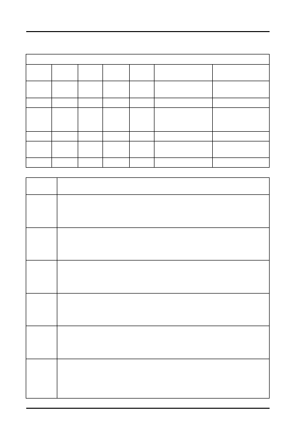
Audi, Seat, Skoda and Volkswagen
46
Table 25 - Adjustment/Operating Conditions
Engine Codes: AAA for vehicles 96 on
Relevant when '1' is displayed in the 5-digit block
X
X
X
X
X
Display Group 4 -
Line 4
Display Group 5 -
Line 4
1
Acceleration
enrichment
Air conditioning
compressor on
1
Full load
Air conditioning on
1
Part load
Gearbox
intervention - auto.
only
1
Idling
Drive range
1
Fuel cut-off on
overrun
Not relevant
Re-test the system Not relevant
Display
Group
Description
1
1. Engine speed.
2. Coolant temperature.
3. Lambda control.
4. Ignition timing.
2
1. Engine speed.
2. Injection period.
3. Battery voltage.
4. EGR status.
3
1. Engine speed
2. Engine load signal.
3. Throttle valve angle.
4. Intake air temperature.
4
1. Lambda control.
2. Multiplicative Lambda adaption value.
3. Additive Lambda adaption value.
4. Tank venting adaption factor.
5
1. Engine speed.
2. Relative engine load.
3. Vehicle speed.
4. Not relevant.
6
1. Engine speed.
2. Idling control adaption requirement.
3. Multiplicative learning value.
4. Signal from aircon compressor (see Table 26 for the relevance of the
figures in line 4).

Audi, Seat, Skoda and Volkswagen
47
Table 26- Compressor State
Engine Codes: AEE for vehicles 96 on
Relevant when '1' is displayed in the 7-digit block
X
X
X
X
X
X
X
Display Group 6 - Aircon
compressor signal
1
Air-conditioning readiness
1
Air conditioning compressor
has cut in
Display
Group
Description
1
1. Engine speed (see note below).
2. Coolant temperature.
3. Lambda probe voltage (fluctuating).
4. Adjustment conditions (see the Table 27 for the relevance of the figures
in line 4).
NOTE: The specification must be attained with the coolant temperature at a minimum
of 80°C, with all electrical ancillaries switched off. Specified for manual gearbox as 640
to 740 rpm (or 830 to 930 rpm for vehicles with control unit 032 906 030D), and for
auto. gearbox as 750 to 850 rpm. On both auto. and manual (without control unit 032
906 030D), the idle speed is increased by the control unit if the battery voltage is too
low or the air conditioner is switched on (up to 900 rpm), and after a long full throttle
drive and higher temperatures (up to 960 rpm).
2
1. Engine speed (see note below).
2. Injection period.
3. Battery voltage.
4. Intake air temperature.
NOTE: The specification must be attained with the coolant temperature at a minimum
of 80°C, with all electrical ancillaries switched off. Specified for manual gearbox as 640
to 740 rpm (or 830 to 930 rpm for vehicles with control unit 032 906 030D), and for
auto. gearbox as 750 to 850 rpm. On both auto. and manual (without control unit 032
906 030D), the idle speed is increased by the control unit if the battery voltage is too
low or the air conditioner is switched on (up to 900 rpm), and after a long full throttle
drive and higher temperatures (up to 960 rpm).
3
1. Engine speed (see note below).
2. Engine load (18 to 28% for manual gearbox, 18 to 29% for auto.
gearbox).
3. Throttle valve angle.
4. Throttle valve position - 17 to 27% for manual gearbox (17 to 33% for
vehicles with control unit 032 906 030D), or 17 to 34% for automatic
gearbox.

Audi, Seat, Skoda and Volkswagen
48
NOTE: The specification must be attained with the coolant temperature at a minimum
of 80°C, with all electrical ancillaries switched off. Specified for manual gearbox as 640
to 740 rpm (or 830 to 930 rpm for vehicles with control unit 032 906 030D), and for
auto. gearbox as 750 to 850 rpm. On both auto. and manual (without control unit 032
906 030D), the idle speed is increased by the control unit if the battery voltage is too
low or the air conditioner is switched on (up to 900 rpm), and after a long full throttle
drive and higher temperatures (up to 960 rpm).
4
1. Engine speed (see note below).
2. Engine load (18 to 28% for manual gearbox, 18 to 29% for auto.
gearbox).
3. Speed signal.
4. Operating condition (see Table 27 for the relevance of the figures in line
4).
NOTE: The specification must be attained with the coolant temperature at a minimum
of 80°C, with all electrical ancillaries switched off. Specified for manual gearbox as 640
to 740 rpm (or 830 to 930 rpm for vehicles with control unit 032 906 030D), and for
auto. gearbox as 750 to 850 rpm. On both auto. and manual (without control unit 032
906 030D), the idle speed is increased by the control unit if the battery voltage is too
low or the air conditioner is switched on (up to 900 rpm), and after a long full throttle
drive and higher temperatures (up to 960 rpm).
5
1. Engine speed.
2. Duty cycle (of activated Charcoal Filter solenoid valve 1, with coolant
temperature at a minimum of 80°C).
3. Not relevant.
4. Not relevant.
6
1. Mixture correction value (fluctuating around 128, in a limitation range of
80 to 150).
2. Not relevant.
3. Not relevant.
4. Throttle valve potentiometer (stored value of basic setting; throttle valve
closed).

Audi, Seat, Skoda and Volkswagen
49
Table 27- Adjustment/Operating Conditions (automatic gearbox retards
ignition for gear change)
Engine Codes: ACK, ALG
Relevant when '1' or '0' is displayed in the 8-digit block
X
X
X
X
X
X
X
X
Display Group 1 - Line
4
Display Group 4 - Line
4
1
Idling contact closed
-
1
AC compressor on
Acceleration
enrichment/lean
mixture on
deceleration
1
Air conditioner on
Full load
0
Torque reduction
(gearshift intervention
in auto gearbox)
-
1
-
Idling contact closed
1
Driving stage
(automatic gearbox)
Overrun cut-off
Display
Group
Description
1
1. Engine speed.
2. Engine load.
3. Throttle valve angle.
4. Ignition angle.
2
1. Engine speed.
2. Engine load.
3. Ignition duration.
4. Intake air mass.
3
1. Engine speed.
2. ECU supply voltage.
3. Engine coolant temperature.
4. Intake air temperature.
4 Idling
Stabilisation
1. Throttle valve angle.
2. Idling intake mass learning valve (automatic gearbox with drive
selected).
3. Idling intake mass learning valve (manual gearbox in neutral -
automatic gearbox in P or N).
4. Operating mode (idle, part load, etc.).
5 Idling
Stabilisation
1. Actual engine speed.
2. Specified engine speed.
3. Idle air mass regulating valve.
4. Intake air mass.

Audi, Seat, Skoda and Volkswagen
50
6 Idling
Stabilisation
1. Engine speed.
2. Injection duration.
3. Bank 1 at idle - lambda learnt valve (additive) (see note below).
4. Bank 2 at idle - lambda learnt valve (additive) (see note below).
NOTE: A negative value indicates a rich mixture, whilst a positive value indicates a lean
mixture
7 Lambda
Learnt Value
1. Bank 1 at part throttle - lambda learnt value (multiplicative) (see
note below).
2. Bank 2 at part throttle - lambda learnt value (multiplicative) (see
note below).
3. Bank 1 at idle - lambda learnt value (additive) (see note below).
4. Bank 2 at idle - lambda learnt value (additive) (see note below).
NOTE: A low value indicates that the engine is running too rich and therefore the ECU
is weakening the mixture.
A high value indicates that the engine is running too weak and therefore the ECU is
enriching the mixture.
Additive: The effects of a fault (e.g. Intake air leak), will reduce as the engine speed
increases, so the injection period will be modified by a fixed amount. This amount is not
dependent on the basic injection duration period.
Multiplicative: The effects of a fault (e.g. Injector fault) will increase as engine speed
increases, so a multiplicative learnt value is a proportional change to the injection
duration. The change is dependent on the basic injection duration period.
8 Lambda
Learnt Value
1. Engine speed.
2. Injection duration.
3. Bank 1 at idle - lambda learnt value (additive) (see note below).
4. Bank 2 at idle - lambda learnt value (additive) (see note below).
NOTE: Additive: The effects of a fault (e.g. Intake air leak), will reduce as the engine
speed increases, so the injection period will be modified by a fixed amount. This
amount is not dependent on the basic injection duration period.
9 Oxygen
Sensor
1. Oxygen sensor voltage - bank 1.
2. Oxygen sensor voltage - bank 2.
3. EVAP canister purge valve duty cycle.
4. Lambda correction factor while fuel tank venting is active.
10 Fuel Tank
Breather
1. EVAP canister purge valve duty cycle.
2. Lambda correction factor with tank breather active.
3. EVAP canister charge level (see Note 1 below).
4. Fuel tank venting system purge rate (see Note 2 below).
NOTE 1: Display = - 5: canister empty Display = 95: canister full
NOTE 2: Display = 0.5: no canister vapours ingested Display = 1.5: 30% of the intake
air mass drawn from the canister

Audi, Seat, Skoda and Volkswagen
51
11 Fuel
Consumption
1. Engine speed.
2. Engine load.
3. Vehicle speed.
4. Fuel consumption.
12 Knock
Control
1. Engine speed.
2. Retardation of ignition timing by knock control - cylinder 1.
3. Retardation of ignition timing by knock control - cylinder 2.
4. Retardation of ignition timing by knock control - cylinder 3.
13 Knock
Control
1. Engine load.
2. Retardation of ignition timing by knock control - cylinder 1.
3. Retardation of ignition timing by knock control - cylinder 2.
4. Retardation of ignition timing by knock control - cylinder 3.
14 Knock
Control
1. Engine speed.
2. Retardation of ignition timing by knock control - cylinder 4.
3. Retardation of ignition timing by knock control - cylinder 5.
4. Retardation of ignition timing by knock control - cylinder 6.
15 Knock
Control
1. Engine load.
2. Retardation of ignition timing by knock control - cylinder 4.
3. Retardation of ignition timing by knock control - cylinder 5.
4. Retardation of ignition timing by knock control - cylinder 6.
16 Knock
Control
1. Engine speed.
2. Engine load.
3. Ignition timing.
4. Total sum of ignition retardation cylinders 1 to 6.
17 Knock
Sensors
1. Engine speed.
2. Knock sensor voltage - cylinder 1.
3. Knock sensor voltage - cylinder 2.
4. Knock sensor voltage - cylinder 3.
18 Knock
Sensors
1. Engine speed.
2. Knock sensor voltage - cylinder 4.
3. Knock sensor voltage - cylinder 5.
4. Knock sensor voltage - cylinder 6.
19 Torque
Reduction
(automatic
gearbox)
1. Engine speed.
2. Engine load.
3. Required engine torque.
4. Actual engine torque.
20 Operating
Modes
1. Engine speed.
2. Automatic gearbox operating mode.
3. A/C operating modes.
4. A/C compressor status.

Audi, Seat, Skoda and Volkswagen
52
21 Lambda
Control
1. Engine speed.
2. Engine load.
3. Engine coolant temperature.
4. Lambda control operating mode.
22
1. This group is not relevant.
23 Throttle
Control part
adaption
1. Learning requirement (for relevance of the figures in line 1 see
Table 28).
2. Throttle valve positioner minimum stop.
3. Throttle valve positioner 'limp home' stop.
4. Throttle valve positioner maximum stop.
24 Traction
Control
1. Engine speed.
2. Reduction stages.
3. Specified engine torque.
4. Actual engine torque.
25 System
Status
1. Engine speed.
2. Engine load.
3. System status (for relevance of the figures in line 1 see Table 29).
4.
26 Camshaft
Timing
Adjustment
1. Engine speed.
2. Engine load.
3. Camshaft position - bank 1.
4. Camshaft position - bank 2.
27 System
Status and
Camshaft
Timing
Adjustments
1. System status (for relevance of the figures in line 1 see Table 30).
2.
3. Camshaft position - bank 1.
4. Camshaft position - bank 2.
95
1. Engine speed.
2. Engine load.
3. Ignition timing.
4. Engine coolant temperature.
98 Throttle
Control
part-matching
1. Throttle valve potentiometer voltage.
2. Throttle valve positioner sensor voltage.
3. Operating mode.
4. Adaption status.
99 Lambda
Regulation
1. Engine speed.
2. Engine coolant temperature.
3. Lambda regulation.
4. Lambda regulation operating mode.

Audi, Seat, Skoda and Volkswagen
53
Table 28 - Throttle Control Learning Requirement
Table 29 - Display group 25 System Status
Table 30 - Display Group 27 System Status
Relevant when '1' or '0' is displayed in the 8-digit block
X
X
X
X
X
X
X
X
Display group 23 - Line 1
0
Not assigned
1
Throttle valve positioner min. stop - learning
process not carried out
1
Throttle valve positioner max stop - learning
process not carried out
1
Throttle valve potentiometer min. stop - learning
process not carried out
1
Throttle valve potentiometer max stop - learning
process not carried out
0
Not assigned
1
Throttle valve positioner to throttle valve
potentiometer - balance not carried out
0
Not assigned
Relevant when '1' is displayed in the 8-digit block
X
X
X
Display group 25 - Line 3
1
Camshaft timing adjustment active.
1
Intake manifold change-over active.
1
See WSM.
Relevant when '1' is displayed in the 8-digit block
X
X
X
Display group 27 - Line 1
1
Camshaft timing adjustment active.
1
Intake manifold change-over active.
1
See WSM.

Audi, Seat, Skoda and Volkswagen
54
Engine Codes: ADR, AEB, AJL, AJP
Display
Group
Description
1
1. Engine speed.
2. Engine load.
3. Throttle valve angle.
4. Ignition angle.
2
1. Engine speed.
2. Engine load.
3. Ignition duration.
4. Intake air mass.
3
1. Engine speed.
2. ECU supply voltage.
3. Engine coolant temperature.
4. Intake air temperature.
4
1. Throttle valve angle.
2. Idling air mass learnt valve (automatic transmission in P or N).
3. Idling air mass learnt valve (manual transmission in neutral or
automatic in drive).
4. Operating mode (idle, part load, etc.).
5 Idling
Stabilisation
1. Actual engine speed.
2. Specified engine speed.
3. Idle air mass regulating valve.
4. Intake air mass.
6 Idling
Stabilisation
1. Engine speed.
2. Idle air mass regulating valve.
3. Lambda regulator.
4. Ignition angle.
7 Lambda
Leant Values
1. Lambda regulator control value.
2. Oxygen sensor voltage.
3. EVAP canister purge valve duty cycle.
4. Lambda correction factor whilst tank venting is active.
8 Lambda
Leant Values
1. Injection duration.
2. Lambda learnt value at idle (additive) (see note below).
3. Lambda learnt value at part load (multiplicative) (see note below).
4. Fuel tank venting operating mode.

Audi, Seat, Skoda and Volkswagen
55
NOTE: A low value indicates that the engine is running too rich and therefore the ECU
is weakening the mixture.
A high value indicates that the engine is running too weak and therefore the ECU is
enriching the mixture.
Additive: The effects of a fault (e.g. Intake air leak), will reduce as the engine speed
increases, so the injection period will be modified by a fixed amount. This amount is not
dependent on the basic injection duration period.
Multiplicative: The effects of a fault (e.g. Injector fault) will increase as engine speed
increases, so a multiplicative learnt value is a proportional change to the injection
duration. The change is dependent on the basic injection duration period.
9 Lambda
Leant Values
1. Engine speed.
2. Lambda regulator control value.
3. Oxygen sensor voltage.
4. Lambda learnt value at idle (additive).
10 Fuel Tank
Venting
1. EVAP canister purge valve duty cycle.
2. Lambda correction factor during active fuel tank venting.
3. Charge level of EVAP canister (see Note 1 below).
4. Fuel tank venting system purge rate (see Note 2 below).
NOTE 1: Value of -3 indicates that the canister is empty, 32 indicates it is full of
vapours.
NOTE 2: Value of 0.0 indicates that the purge valve is closed, 0.3 indicates that 30% of
the intake air mass is from the EVAP canister.
11 Fuel
Consumption
1. Engine speed.
2. Engine load.
3. Vehicle speed.
4. Fuel consumption.
12 Fuel
Consumption
(code AJP)
1. Engine speed.
2. Battery voltage.
3. Fuel consumption.
4. Ignition timing.
13 Knock
Control
(code AJP)
1. Retardation of ignition timing by knock control - cylinder 1.
2. Retardation of ignition timing by knock control - cylinder 2.
3. Retardation of ignition timing by knock control - cylinder 3.
4. Retardation of ignition timing by knock control - cylinder 4.
14 Knock
Control
1. Engine speed.
2. Engine load.
3. Retardation of ignition timing by knock control - cylinder 1.
4. Retardation of ignition timing by knock control - cylinder 2.
15 Knock
Control
1. Engine speed.
2. Engine load.
3. Retardation of ignition timing by knock control - cylinder 3.
4. Retardation of ignition timing by knock control - cylinder 4.

Audi, Seat, Skoda and Volkswagen
56
16 Knock
Control
1. Cylinder 1 knock sensor voltage.
2. Cylinder 2 knock sensor voltage.
3. Cylinder 3 knock sensor voltage.
4. Cylinder 4 knock sensor voltage.
18 Altitude
adaption
1. Engine speed.
2. Engine load.
3. Throttle valve angle (engine load).
4. Altitude correction factor.
19 Torque
Reduction
(automatic
gearbox)
1. Engine speed.
2. Engine load.
3. Ignition angle retardation.
4. Ignition timing.
20O
perasting
Modes
1. Engine speed.
2. Automatic gearbox operating mode.
3. A/C operating mode.
4. A/C compressor operating mode.
21 Lambda
Control
1. Engine speed.
2. Engine load.
3. Engine coolant temperature.
4. Lambda control operating mode.
23 Adaption
of throttle
Valve Control
part
1. Learning requirement (for the relevance of this data see Table 31).
2. Throttle valve minimum position.
3. Throttle valve 'limp home' running position.
4. Throttle valve maximum position.
24 Knock
Control
1. Engine speed.
2. Engine load.
3. Ignition timing.
4. Sum of the cylinders 1 to 4 ignition retardation angles.
25 Intake
change-over/
camshaft
adjustment
(code ADR/
AJP)
1. Engine operating mode.
2. Hall sensor adjustment deviation.
3. Intake manifold/camshaft adjustment operating mode (for the
relevance of this data see Table 32).
4. Active camshaft adjustment angle.
25 Charge
Pressure
Control (AEB
only)
1. Specified engine load (from accelerator pedal).
2. Specified engine load after correction by knock control etc.
3. Actual engine load.
4. Charge pressure limitation valve duty cycle.
26 Camshaft
Adjustment
1. Engine speed.
2. Engine load.
3. Intake manifold/camshaft adjustment operating mode.
4. Active camshaft adjustment angle.

Audi, Seat, Skoda and Volkswagen
57
Table 31 - Throttle Control Learning Requirements
95
1. Engine speed.
2. Engine load.
3. Ignition timing.
4. Engine coolant temperature.
98 Matching
Throttle
Control part
1. Throttle valve potentiometer voltage.
2. Throttle valve positioner potentiometer voltage.
3. Engine operating mode.
4. Throttle control part matching mode.
99 Lambda
Regulation
1. Engine speed.
2. Engine coolant temperature.
3. Lambda control.
4. Operating condition.
Relevant when '1' is displayed in the 6-digit block
X
X
X
X
X
X
Display group 23 - Line 1
1
Throttle valve positioner Min.
stop signal - learning process
(0=Learning process OK,
1=Learning process required)
1
Throttle valve positioner Max.
stop signal - learning process
(0=Learning process OK,
1=Learning process required)
1
Learning process throttle
valve potentiometer Min. stop
(0=Learning process OK,
1=Learning process required)
1
Learning process throttle
valve potentiometer Max. stop
(0=Learning process OK,
1=Learning process required)
1
Not assigned
1
Throttle valve potentiometer
being balanced with throttle
valve positioner (0=Balance
required, 1=Balance OK)

Audi, Seat, Skoda and Volkswagen
58
Table 32 - Intake Manifold/Camshaft Adjustment Operating Mode
Engine Codes: 1Z (03.94-on), AEY, AFN, ALE, AVG
Relevant when '1' is displayed in the 3-digit block
X
X
X
Display group 25 - Line 3
1
1= Camshaft advanced
1
1= Long intake manifold track
0
Not assigned
Display
Group
Description
1 Injected
Quantity
1. Engine speed.
2. Injected quantity.
3. Modulating piston movement sensor voltage.
4. Engine coolant temperature.
2 Idling
Speed
1. Engine speed.
2. Accelerator pedal position.
3. Operating condition (for the relevance of this data see Table 33).
4. Engine coolant temperature.
3 EGR
System
1. Engine speed.
2. Specified intake air mass.
3. Actual intake air mass.
4. EGR valve duty cycle.
4 Injection
Commencem
ent
1. Engine speed.
2. Specified injection commencement.
3. Actual injection commencement.
4. Commencement-of-injection valve duty cycle.
4 Injection
Commencem
ent at Full
Throttle (3d
gear)
1. Engine speed.
2. Specified injection commencement.
3. Actual injection commencement.
4. Commencement-of-injection valve duty cycle.
5 Starting
Conditions
1. Engine speed.
2. Starting injection quantity.
3. Actual commencement of injection.
4. Engine coolant temperature.
6 Switch
Positions
1. Vehicle speed.
2. Brake pedal monitor (for the relevance of this data see Table 34).
3. Cruise control system (CCS) (for the relevance of this data see
Table 35).
4. Cruise control system.

Audi, Seat, Skoda and Volkswagen
59
7
Temperatures
1. Fuel temperature.
2. Not allocated.
3. Intake manifold temperature.
4. Engine coolant temperature.
8 Limitation of
Injection
Quantity at
full throttle
(3rd gear)
1. Engine speed.
2. Injected quantity (from accelerator pedal position).
3. Injection quantity limitation (torque limitation).
4. Injection quantity limitation (smoke prevention).
9 Limitation of
Injection
Quantity
1. Engine speed.
2. Injection quantity (Cruise control system active).
3. Injection limitation from automatic gearbox during gear change.
4. Modulating piston movement sensor voltage.
10 Air
Quantities at
full throttle
(3rd gear)
1. Intake air mass.
2. Atmospheric pressure.
3. Intake manifold pressure.
4. Accelerator pedal position.
11 Turbo
Charge
Pressure
Control at full
throttle (3rd
gear)
1. Engine speed.
2. Specified turbo charge pressure.
3. Actual turbo charge pressure.
4. Charge pressure control valve solenoid duty cycle (see note
below).
NOTE: Engine code AEY: Throttle valve positioner duty cycle.
12 Glow
Plugs
1. Not allocated
2. Pre-glow period.
3. Supply voltage from control unit.
4. Engine coolant temperature.
13 Idle speed
smooth
running
control (see
note below)
1. Difference in injected quantity between cylinders 4 and 3.
2. Difference in injected quantity between cylinders 2 and 3.
3. Difference in injected quantity between cylinders 1 and 3.
4.
NOTE: The injection system is equipped with an idle speed smooth running control.
Any power differences between the cylinders is recognised and equalised via selective
injected quantities.
16 Additional
Heating (AFN
>08.97)
1. Alternator loading.
2. Additional heater conditions (for the relevance of this data see
Table 36).
3. Heater element activation (for the relevance of this data see Table
37).
4. Control unit voltage supply.
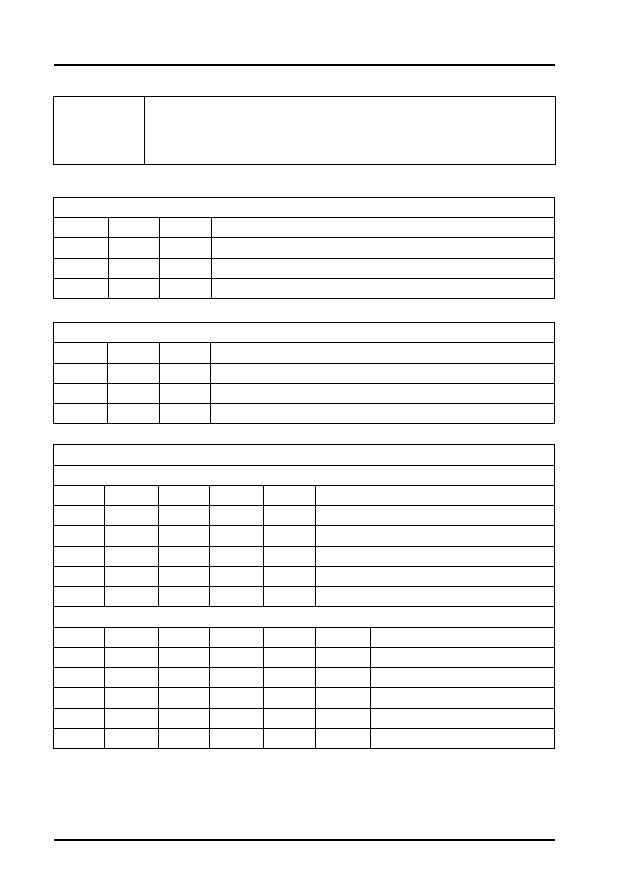
Audi, Seat, Skoda and Volkswagen
60
Table 33 - Group 2 Operating Conditions
Table 34 - Group 6 Brake Pedal Monitor
Table 35 - Group 6 Cruise Control Monitor
19 (code 1Z)
1. Modulating piston voltage at minimum stop.
2. Modulating piston voltage at maximum stop.
3.
4.
Relevant when '1' is displayed in the 3-digit block
X
X
X
Display group 2 - Line 3
1
A/C compressor switched on
1
Idling switch closed
1
Idle speed increased due to A/C
Relevant when '1' is displayed in the 3-digit block
X
X
X
Display group 6 - Line 2
1
Brake light switch closed
1
Brake pedal switch open
1
Clutch pedal switch open
Relevant when '1' is displayed in the 5 & 6-digit blocks
All except code ALE
X
X
X
X
X
Display group 6 - Line 3
1
CCS switched on
1
Speed accepted
1
Speed accepted again
1
Brake pedal depressed
1
Clutch pedal depressed
Code ALE only
X
X
X
X
X
X
Display group 6 - Line 3
1
CCS switched on
1
1
Speed accepted
1
1
Speed accepted again
1
1
Brake pedal depressed
1
1
Clutch pedal depressed
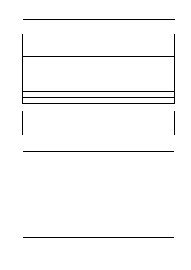
Audi, Seat, Skoda and Volkswagen
61
Table 36 - Additional Heater Conditions
Table 37 - Group 16 Heater Element Activation
Engine Codes: AFB, AKE and AKN
Relevant when '1' is displayed in the 8-digit blocks
X
X
X
X
X
X
X
X
Display group 16 - Line 2
1
Coolant temperature above 70 to 80°C, or intake
air temperature above 5°C
1
Alternator defective
1
Battery voltage below 9V
1
Engine speed below 760 rpm
1
Engine start within the last 10 secs
1
Coolant or Intake manifold temperature sensor
defective
1
Not assigned
1
Not assigned
Relevant when '1' is displayed in the 2-digit blocks
X
X
Display group 16 - Line 3
1
Low heat output relay on
1
High heat output relay on
Display Groups
Description
1 Injected
Quantity
1. Engine speed.
2. Injection quantity.
3. Injection duration.
4. Engine coolant temperature.
2 Idle Speed
1. Engine speed.
2. Accelerator pedal position.
3. Operating conditions (for the relevance of this display line, see
Table 38).
4. Engine coolant temperature.
3 EGR System
1. Engine speed.
2. Specified intake air mass.
3. Actual intake air mass.
4. EGR valve duty cycle.
4 Injection
Commencement
1. Engine speed.
2. Specified injection commencement.
3. Actual injection commencement.
4. Injection commencement valve duty cycle.

Audi, Seat, Skoda and Volkswagen
62
4 Injection
Commencement
at full load
1. Engine speed.
2. Specified injection commencement.
3. Actual injection commencement.
4. Injection commencement valve duty cycle.
5 Starting
Conditions
1. Engine speed.
2. Starting quantity.
3. Actual commencement of injection.
4. Engine coolant temperature.
6 Switch
Positions
1. Vehicle speed.
2. Brake pedal position (for the relevance of this display line, see
Table 39).
3. Cruise control system (for the relevance of this display line, see
Table 40).
4. Cruise control system status (see note below).
NOTE: Vehicles without cruise control = 255, Cruise control switched off = 0, Cruise
control switched on = 1
7 Temperatures
1. Fuel temperature.
2. Oil temperature.
3. Intake air temperature.
4. Engine coolant temperature.
8 Injection
Limitation at full
load
1. Engine speed.
2. Injection requirement from accelerator pedal.
3. Injected quantity limitation (torque reduction).
4. Injected quantity limitation (smoke prevention).
9 Injection
Limitation at full
load
1. Injection requirement from accelerator pedal.
2. Injection limitation during gear change (automatic
transmission).
3. Injected quantity due to engine braking effect.
4. Injection quantity limitation due to traction control.
10 Air Quantities
at full load
1. Intake air mass.
2. Atmospheric pressure.
3. Intake manifold pressure.
4. Accelerator pedal position.
11 Turbo Charge
Pressure Control
1. Engine speed.
2. Specified turbo charge pressure.
3. Actual turbo charge pressure.
4. Charge pressure control valve duty cycle.
12 Glow Plugs
1.
2. Pre-glow period.
3. ECU supply voltage.
4. Engine coolant temperature.

Audi, Seat, Skoda and Volkswagen
63
13 Idle Speed
Smooth Running
Control (see note
below)
1. Injection quantity variation between cylinders 3 and 2.
2. Injection quantity variation between cylinders 1 and 2.
3. Not allocated
4. Not allocated
NOTE: The injection system is equipped with an idle speed smooth running control.
Any power differences between the cylinders is recognised and equalised via selective
injected quantities.
14 Idle Speed
Smooth Running
Control (see note
below)
1. Not allocated
2. Injection quantity variation between cylinders 6 and 2.
3. Injection quantity variation between cylinders 4 and 2.
4. Injection quantity variation between cylinders 5 and 2.
NOTE: The injection system is equipped with an idle speed smooth running control.
Any power differences between the cylinders is recognised and equalised via selective
injected quantities.
15 Fuel
Consumption
1. Engine speed.
2. Actual injection quantity.
3. Fuel consumption
4. Injection quantity requirement from accelerator pedal
18 Fuel Injection
Pump
1. Injection pump voltage supply.
2. Voltage supply from the ECU.
3. Injection pump status (for the relevance of this display line, see
Table 41).
4.
19 Starting
1. Injection pump speed.
2. Start of delivery.
3. Metering solenoid valve activation period.
4. Fuel temperature
20 Idling
1. Fuel quantity diagnosis operating conditions (for the relevance
of this display line, see Table 42).
2. Injection condition (for the relevance of this display line, see
Table 43).
3. Fuel pump status.
4. Fault recognised (0 = no fault)
125 Data Bus
Communication
1. Gearbox status (see note below).
2. ABS status (see note below).
3. Instrument cluster status (see note below).
4. Air bag status (see note below).
NOTE: Display = 1 when control units with active data bus are fitted
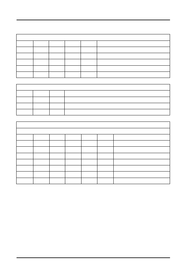
Audi, Seat, Skoda and Volkswagen
64
Table 38 - Group 2 Idle Speed Operating Conditions
Table 39 - Group 6 Brake Pedal Position Monitor
Table 40 - Group 6 Cruise Control System Monitor
Relevant when '1' is displayed in the 5-digit blocks
X
X
X
X
X
Display group 2 - Line 3
1
A/C compressor switch on
1
Not assigned
1
Idle switch closed
1
Kick down switch closed
1
System fault recognised
Relevant when '1' is displayed in the 3-digit block
X
X
X
Display group 6 - Line 2
1
Brake light switch closed
1
Brake pedal switch open
1
Clutch pedal switch open
Relevant when '1' and '0' are displayed in the 6-digit blocks
All except code ALE
X
X
X
X
X
X
Display group 6 - Line 3
0
0
0
0
0
0
CCS switched off
0
0
0
0
0
1
CCS and memory switched off
0
0
0
0
1
1
CCS switched on
0
0
1
0
1
1
Resume speed again
0
0
0
1
1
1
CCS button pressed
0
1
0
0
1
1
Brake pedal depressed
1
0
0
0
1
1
Clutch pedal depressed

Audi, Seat, Skoda and Volkswagen
65
Table 41 - Fuel Injection Pump Status
Table 42 - Fuel Quantity Diagnosis Operating Conditions
Table 43 - Group 20 Injection Conditions
Relevant when '1' is displayed in the 8-digit blocks
X
X
X
X
X
X
X
X
Display group 18 - Line 3
1
Constant voltage supply to metering solenoid
valve
1
Metering solenoid valve defective
1
Injection pump speed sensor defective
1
Timing adjustment defective
1
Commencement of injection not recognised
1
See WSM
1
Engine speed not recognised
1
Data wiring defective
Relevant when '1' is displayed in the 3-digit blocks
X
X
X
Display group 20 - Line 1
1
'Refuel' warning from instrument cluster
1
'Tank almost empty' signal from sender
1
'Tank empty' signal from sender
Relevant when '1' is displayed in the 5-digit blocks
X
X
X
X
X
Display group 20 - Line 2
1
'Switch off' being prepared
1
Not assigned
1
Engine start prevented due to low fuel
level
1
Engine stopped after starting due to low
fuel level
1
Engine stopped - no fuel

Audi, Seat, Skoda and Volkswagen
66
Engine Codes: AFF, AHU and AHH
Display Group
Description
1 Injected
Quantity
1. Engine speed.
2. Injection quantity.
3. Modulating piston movement sensor voltage.
4. Engine coolant temperature.
2 Idling Speed
1. Engine speed.
2. Accelerator pedal position.
3. Operating condition (for the relevance of this display line, see
Table 44).
4. Engine coolant temperature.
3 EGR System
1. Engine speed.
2. Specified intake air mass.
3. Actual intake air mass.
4. EGR valve duty cycle.
4 Injection
Commencement
1. Engine speed.
2. Specified injection commencement.
3. Actual injection commencement.
4. Commencement-of-injection valve duty cycle.
4 Injection
Commencement
at full throttle
(3rd gear)
1. Engine speed.
2. Specified injection commencement.
3. Actual injection commencement.
4. Commencement-of-injection valve duty cycle.
5 Starting
Conditions
1. Engine speed.
2. Starting injection quantity.
3. Actual commencement of injection.
4. Engine coolant temperature.
6 Switch
Positions
1. Vehicle speed.
2. Brake pedal monitor (for the relevance of this display line, see
Table 45).
3. Cruise control system (CCS) (for the relevance of this display
line, see Table 46).
4. Cruise control system (see note below).
NOTE: Vehicles with cruise control = 0/1, without cruise control = 255
7 Temperatures
1. Fuel temperature.
2.
3. Intake manifold pressure.
4. Engine coolant temperature.
8 Limitation of
Injection
Quantity at full
throttle (3rd
gear)
1. Engine speed.
2. Injected quantity (from accelerator pedal).
3. Injected quantity limitation (torque limitation).
4. Injected quantity limitation (smoke prevention).

Audi, Seat, Skoda and Volkswagen
67
9 Limitation of
Injection
Quantity
1. Engine speed.
2. Injection quantity (Cruise control system active).
3. Injection limitation from automatic gearbox during gear change.
4. Modulating piston movement sensor voltage.
10 Air Quantities
at full throttle
(3rd gear)
1. Intake air mass.
2. Atmospheric pressure.
3. Intake manifold pressure.
4. Accelerator pedal position.
11 Turbo Charge
Pressure Control
at full throttle
(3rd gear)
1. Engine speed.
2. Specified charge pressure.
3. Actual charge pressure.
4. Turbo charge pressure control valve duty cycle.
12 Glow Plugs
1.
2. Pre-glow period.
3. ECU supply voltage.
4. Engine coolant temperature.
13 Idle smooth
running control
(see note below)
1. Difference in injected quantity between cylinders 4 and 3.
2. Difference in injected quantity between cylinders 2 and 3.
3. Difference in injected quantity between cylinders 1 and 3
4. Difference between injection quantity between cylinders 1, 2, 4
and 3 (code AFF)
NOTE: The injection system is equipped with an idle speed smooth running control.
Any power differences between the cylinders is recognised and equalised via
selective injected quantities.
15 Fuel
Consumption
1. Engine speed.
2. Actual injection quantity.
3. Fuel consumption.
4. Injection quantity requirement (from accelerator pedal sensor).
16 Additional
Heater
1. Alternator loading.
2. Additional heater condition (for the relevance of this display
line, see Table 47).
3. Activation of heater elements (for the relevance of this display
line, see Table 48).
4. Voltage supply from control unit.
19 Quantity
adjuster (AHH,
AHU <08.97,
AFF)
1. Modulating piston movement sensor - stop position voltage.
2. Modulating piston movement sensor - start position voltage.
3. Not allocated
4. Not allocated
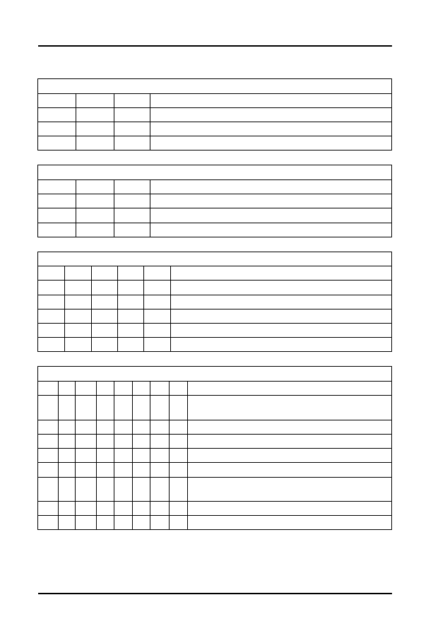
Audi, Seat, Skoda and Volkswagen
68
Table 44 - Idling Speed Operating Conditions
Table 45 - Group 6 Brake Pedal Monitoring
Table 46 - Group 6 Cruise Control System Monitoring
Table 47 - Group 16 Additional Heater Condition
Relevant when '1' is displayed in the 3-digit block
X
X
X
Display group 2 - Line 3
1
A/C compressor switched on
1
Idling switch closed
1
Idle speed increased due to A/C
Relevant when '1' is displayed in the 3-digit block
X
X
X
Display group 6 - Line 2
1
Brake light switch closed
1
Brake pedal switch open
1
Clutch pedal switch open
Relevant when '1' is displayed in the 5-digit blocks
X
X
X
X
X
Display group 6 - Line 3
1
CCS switched on
1
Speed accepted
1
Speed accepted again
1
Brake pedal depressed
1
Clutch pedal depressed
Relevant when '1' is displayed in the 8-digit blocks
X
X
X
X
X
X
X
X
Display group 16 - Line 2
1
Coolant temperature above 70 to 80°C, or intake
air temperature above 5°C
1
Alternator defective
1
Battery voltage below 9V
1
Engine speed below 760 rpm
1
Engine start within the last 10 secs
1
Coolant or Intake manifold temperature sensor
defective
1
Not assigned
1
Not assigned

Audi, Seat, Skoda and Volkswagen
69
Table 48 - Group 16 Activation of Heater Elements
Engine Codes: AJM, ATD and ATJ
Relevant when '1' is displayed in the 2-digit blocks
X
X
Display group 16 - Line 3
1
Low heat output relay on
1
High heat output relay on
Display
Groups
Description
1 Injected
Quantity
1. Engine speed.
2. Injected quantity.
3. Injection duration.
4. Engine coolant temperature.
2 Idle Speed
1. Engine speed.
2. Accelerator pedal position.
3. Operating condition (for the relevance of this display line, see Table
49).
4. Engine coolant temperature.
3 EGR
System
1. Engine speed.
2. Specified intake air mass.
3. Actual intake air mass.
4. EGR valve duty cycle.
4 Unit Injector
Valve
activation
1. Engine speed.
2. Specified commencement of injection.
3. Injection duration.
4. Synchronisation angle.
4 Unit Injector
Valve
activation at
full load (3rd
gear)
1. Engine speed.
2. Specified commencement of injection.
3. Injection duration.
4. Synchronisation angle.
5 Starting
Conditions
1. Engine speed.
2. Starting quantity
3. Commencement of injection.
4. Engine coolant temperature.
6 Switch
Position
1. Vehicle speed.
2. Brake/clutch pedal positions (for the relevance of this display line,
see Table 50).
3. Accelerator pedal position.
4. Cruise control system (CCS) (see note below).
NOTE: Vehicles with cruise control = 0/1, without cruise control = 255

Audi, Seat, Skoda and Volkswagen
70
7
Temperatures
1. Fuel temperature.
2. Fuel cooling status
3. Intake manifold temperature.
4. Engine coolant temperature.
8 Injected
Quantity
Limitation at
full load (3rd
gear)
1. Engine speed.
2. Injected quantity.
3. Injected quantity limitation (torque limitation).
4. Injected quantity limitation (smoke prevention).
9 Injected
Quantity
Limitation
1. Engine speed.
2. Injected quantity (CCS active).
3. Injected quantity limitation from AT gearbox during gear change.
4. Quantity limitation.
10 Air
Quantities at
full load (3rd
gear)
1. Intake air mass.
2. Atmospheric pressure.
3. Intake manifold pressure.
4. Accelerator pedal position.
11 Turbo
Charge
Pressure
Control at full
load (3rd
gear)
1. Engine speed.
2. Specified turbo charge pressure.
3. Actual turbo charge pressure.
4. Charge pressure control valve duty cycle.
12 Glow Plug
System
1. Glow status
2. Pre-glow period.
3. ECU supply voltage.
4. Engine coolant temperature.
13 Idle
Smooth
Running
Control (see
note below)
1. Smooth running control injected quantity - cylinder 1.
2. Smooth running control injected quantity - cylinder 2.
3. Smooth running control injected quantity - cylinder 3.
4. Smooth running control injected quantity - cylinder 4
NOTE: The injection system is equipped with an idle speed smooth running control. Any
power differences between the cylinders is recognised and equalised via selective
injected quantities.
15 Fuel
Consumption
1. Engine speed.
2. Actual injected quantity.
3. Fuel consumption.
4. Injection quantity requirement.
16 Additional
Heater
1. Alternator loading.
2. Additional heater (for the relevance of this display line, see Table
51).
3. Activation of heater elements (for the relevance of this display line,
see Table 52).
4. ECU supply voltage.
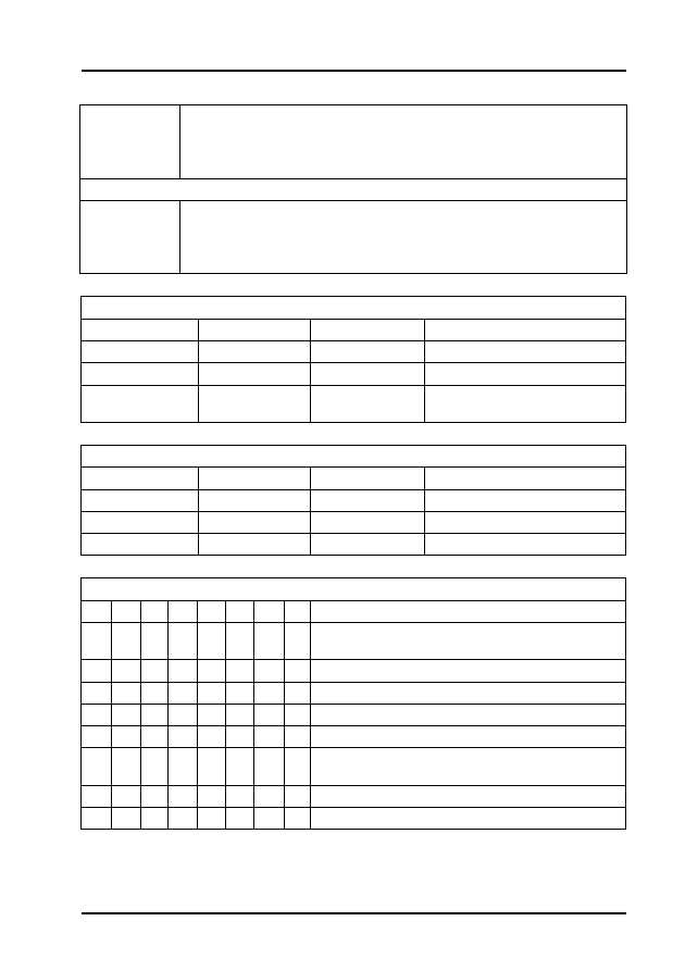
Audi, Seat, Skoda and Volkswagen
71
Table 49 - Group 2 Idle Speed Operating Condition
Table 50 - Group 6 Brake/Clutch Pedal Positions
Table 51 - Group 16 Additional Heater Condition
18 Unit
injector valve
status (see
note below)
1. Cylinder 1 injector status.
2. Cylinder 2 injector status.
3. Cylinder 3 injector status
4. Cylinder 4 injector status
NOTE: 0 = Unit injector OK 1 = Fault
125 Data Bus
Messages
1. Gearbox status.
2. ABS status.
3. Instrument cluster status.
4. Airbag status.
Relevant when '1' is displayed in the 3-digit block
X
X
X
Display group 2 - Line 3
1
A/C compressor switched on
1
Idling switch closed
1
Idle speed increased due to A/
C
Relevant when '1' is displayed in the 3-digit block
X
X
X
Display group 6 - Line 2
1
Brake light switch closed
1
Brake pedal switch open
1
Clutch pedal switch open
Relevant when '1' is displayed in the 8-digit blocks
X
X
X
X
X
X
X
X
Display group 16 - Line 2
1
Coolant temperature above 70 to 80°C, or intake
air temperature above 5°C
1
Alternator defective
1
Battery voltage below 9V
1
Engine speed below 760 rpm
1
Engine start within the last 10 secs
1
Coolant or Intake manifold temperature sensor
defective
1
Not assigned
1
Not assigned
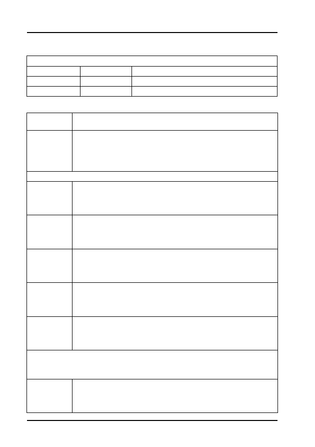
Audi, Seat, Skoda and Volkswagen
72
Table 52 - Group 16 Activation of Heater Elements
Engine Codes: ANA
Relevant when '1' is displayed in the 2-digit blocks
X
X
Display group 16 - Line 3
1
Low heat output relay on
1
High heat output relay on
Display
Code
Description
1 Lambda
Control
1. Engine speed.
2. Engine coolant temperature.
3. Lambda control (see note below)
4. Operating condition (for the relevance of this display line, see Table
53).
NOTE: Minus value indicates a weak mixture, positive value indicates a rich mixture
2 Injection
Duration
1. Engine speed.
2. Engine load.
3. Injection duration.
4. Intake air mass.
3 Ignition
Timing
1. Engine speed.
2. Intake air mass (engine load).
3. Throttle valve angle sensor 1.
4. Ignition timing.
4
Temperature
1. Engine speed.
2. ECU supply voltage.
3. Engine coolant temperature.
4. Intake air temperature.
5 Operating
Mode
1. Engine speed.
2. Engine load.
3. Vehicle speed.
4. Operating mode (idle, part load, etc.).
6 Altitude
Correction
1. Engine speed
2. Engine load.
3. Intake air temperature.
4. Altitude correction factor (see note below).
NOTE: At sea level value should be +5 to -10
1000m value should be -5 to -20
2000m value should be -10 to -30
10 Ignition
1. Engine speed.
2. Engine load.
3. Throttle valve angle.
4. Ignition timing.

Audi, Seat, Skoda and Volkswagen
73
12 Distributor
Settings
1. Engine speed.
2. Engine load.
3. No. of the teeth on the crank sender wheel when the Hall sensor
signal changes from - to + (see note below).
4. No. of teeth on the crank sender wheel when the Hall sensor signal
changes from + to - (see note below).
NOTE: The engine speed sensor on the crankshaft transmits both the engine speed
signal and a reference for crankshaft position. The reference signal is generated by a
gap in the sender wheel. The Hall sensor rotor ring on the camshaft has a 180° division
so that for half a camshaft revolution the window for the Hall sensor is covered, and for
the other half revolution the window is exposed. To synchronise the components when
starting, the ECU records the instant the Hall sensor rotor ring begins to cover the
window (signal changes from - to +) and the instant the window begins to be exposed
(signal changes from + to -). When the reference mark signal from the crank sensor is
detected, the ECU counts the number of teeth on the crankshaft mounted sender
wheel, As soon as it has counted between 26 an 30 teeth after the reference gap, the
signal from the Hall sensor should change from - to +. After between 86 an 90 teeth, the
Hall sensor signal should change from + to -.
14 Misfire
Recognition
1. Engine speed.
2. Engine load.
3. Misfire total (see note below).
4. Misfire recognition status.
NOTE: This specification is only valid for 5 mins after the engine has been started.
15 Misfire
Recognition
1. Cylinder 1 misfire.
2. Cylinder 2 misfire.
3. Cylinder 3 misfire.
4. Misfire recognition status.
16 Misfire
Recognition
1. Cylinder 4 misfire.
2. Not allocated
3. Not allocated
4. Misfire recognition status.
20 Knock
Control
1. Retardation of ignition timing by knock control - cylinder 1.
2. Retardation of ignition timing by knock control - cylinder 2.
3. Retardation of ignition timing by knock control - cylinder 3.
4. Retardation of ignition timing by knock control - cylinder 4
22 Knock
Control
1. Engine speed.
2. Engine load.
3. Retardation of ignition timing by knock control - cylinder 1.
4. Retardation of ignition timing by knock control - cylinder 2.
23 Knock
Control
1. Engine speed.
2. Engine load.
3. Retardation of ignition timing by knock control - cylinder 3.
4. Retardation of ignition timing by knock control - cylinder 4.

Audi, Seat, Skoda and Volkswagen
74
30 Lambda
Regulation
1. Lambda status pre-catalyst (for the relevance of this display line,
see Table 54).
2. Lambda status post-catalyst (for the relevance of this display line,
see Table 54).
3.
4.
31 Oxygen
Sensor
1. Oxygen sensor actual voltage.
2. Oxygen sensor specified voltage.
3. Not allocated
4. Not allocated
32Lambda
Learnt Values
1. Lambda learnt value at idling speed (additive) (see note below).
2. Lambda learnt value at part load (multiplicative) (see note below).
3. Not allocated
4. Not allocated
NOTE: A low value indicates that the engine is running too rich and therefore the ECU
is weakening the mixture.
A high value indicates that the engine is running too weak and therefore the ECU is
enriching the mixture.
Additive: The effects of a fault (e.g. Intake air leak), will reduce as the engine speed
increases, so the injection period will be modified by a fixed amount. This amount is not
dependent on the basic injection duration period.
Multiplicative: The effects of a fault (e.g. Injector fault) will increase as engine speed
increases, so a multiplicative learnt value is a proportional change to the injection
duration. The change is dependent on the basic injection duration period.
33 Lambda
Regulation
1. Pre-catalyst lambda regulation.
2. Pre-catalyst oxygen sensor voltage.
3. Not allocated
4. Not allocated
34 Lambda
Regulation
1. Engine speed.
2. Catalyst temperature (see Note 1 below).
3. Dynamic factor (see Note 2 below).
4. Result of pre-catalyst oxygen sensor age test (see Note 2 below)
NOTE 1: Calculated value from engine speed and load.
NOTE 2: The dynamic factor is an Oxygen sensor ageing measurement. The ECU
compares the adjustment frequency of the sensors' evaluation circuitry with a stored
specification. If the value is not reached, the text 'B1-P1 n/OK' is displayed in zone 4.
41 Lambda
Regulation
1. Pre-catalyst oxygen sensor internal resistance.
2. Pre-catalyst oxygen sensor heating status.
3. Post-catalyst oxygen sensor internal resistance.
4. Post-catalyst oxygen sensor heating status.
43
Post-catalyst
Oxygen
Sensor
1. Engine speed.
2. Catalyst temperature.
3. Oxygen sensor voltage.
4. Result of oxygen sensor test.

Audi, Seat, Skoda and Volkswagen
75
46 Catalyst
Diagnosis
1. Engine speed.
2. Catalyst temperature.
3. Catalyst conversion measured value.
4. Result of catalyst conversion test.
50 Idle Speed
Regulation
1. Actual engine speed.
2. Specified engine speed.
3. A/C operating condition.
4. A/C compressor operating condition.
54 Idling
Control
1. Engine speed.
2. Operating mode (idle, part load, etc.).
3. Accelerator pedal position sensor 1.
4. Throttle valve angle sensor 1.
55 Idling
Control
1. Engine speed.
2. Idle speed regulator.
3. Idle speed stabilisation learning value.
4. Operating condition (for the relevance of this display line, see Table
55).
56 Idling
Control
1. Actual engine speed.
2. Specified engine speed.
3. Idle speed regulator.
4. Operating mode (for the relevance of this display line, see Table
56).
60 Electronic
Throttle
System
1. Throttle valve angle (sensor 1).
2. Throttle valve angle (sensor 2).
3. Learning step counter (see WSM)
4. Adaptation condition.
62 Electronic
Throttle
System
1. Throttle valve angle (sensor 1).
2. Throttle valve angle (sensor 2).
3. Accelerator pedal position (sensor 1)
4. Accelerator pedal position (sensor 2).
63 Kick-down
Adaption
1. Hold down the accelerator pedal.
2. Not allocated
3. Not allocated
4. Not allocated
66 Cruise
Control
System
(CCS)
1. Actual vehicle speed.
2. Brake, clutch and CCS switch positions (for the relevance of this
display line, see Table 57).
3. Specified vehicle speed (last value stored by CCS).
4. CCS switch position (for the relevance of this display line, see Table
58).

Audi, Seat, Skoda and Volkswagen
76
70 EVAP
System
Diagnosis
1. EVAP canister solenoid valve duty cycle.
2. Lambda regulation during TVV diagnosis (see note below).
3. Idle speed deviation during TVV diagnosis.
4. Result of diagnosis (see note below).
NOTE: TVV = Fuel tank vent valve
Negative valve = Canister full.
Positive value = Canister empty.
77 Secondary
Air Injection
System
1. Engine speed.
2. Engine coolant temperature.
3. Not allocated
4. Result of test.
86 Readiness
Code
1. Readiness code (for the relevance of this display line, see Table
59).
2. Not allocated
3. Not allocated
4. Not allocated
95 Variable
Intake
Manifold
1. Engine speed.
2. Engine load.
3. Engine coolant temperature.
4. Variable manifold status (see note below).
NOTE: During rapid accelerator operation (up to 2000 rpm), the status must change
from OFF to ON.
99 Lambda
Regulation
1. Engine speed.
2. Engine coolant temperature.
3. Lambda regulator.
4. Lambda regulator operating condition.
120 Traction
Control
1. Engine speed.
2. Specified engine load.
3. Actual engine load.
4. Status.
122
Automatic
Transmission
1. Engine speed.
2. Specified engine load.
3. Actual engine load.
4. Status.

Audi, Seat, Skoda and Volkswagen
77
Table 53 - Group 1 Operating Condition
Table 54 - Group 30 Lambda Regulation
Table 55 - Group 55 Operating Conditions
Table 56 - Group 56 Idle Control Operating Mode
Relevant when '1' is displayed in the 8-digit blocks
X
X
X
X
X
X
X
X
Display group 1 - Line 4
1
Coolant temperature above 80°C
1
Speed below 2000 rpm
1
Throttle valve closed
1
Lambda regulation OK
1
Idle switch closed
1
A/C compressor switch off
1
Not assigned
1
No faults recognised
Relevant when '1' is displayed in the 3-digit blocks
X
X
X
Display group 30 - Lines 1 & 2
1
Lambda regulation active
1
Oxygen sensor operationally
ready
1
Oxygen sensor heating on
Relevant when '1' is displayed in the 5-digit blocks
X
X
X
X
X
Display group 55 - Line 4
1
A/C compressor switch on
1
Selected gear
1
A/C system switched on
X
Not relevant
1
PAS pressure switch on
Relevant when '1' is displayed in the 5-digit blocks
X
X
X
X
X
Display group 56 - Line 4
1
A/C compressor switch on
1
Selected gear
1
A/C system switched on
X
Not relevant
1
PAS pressure switch on
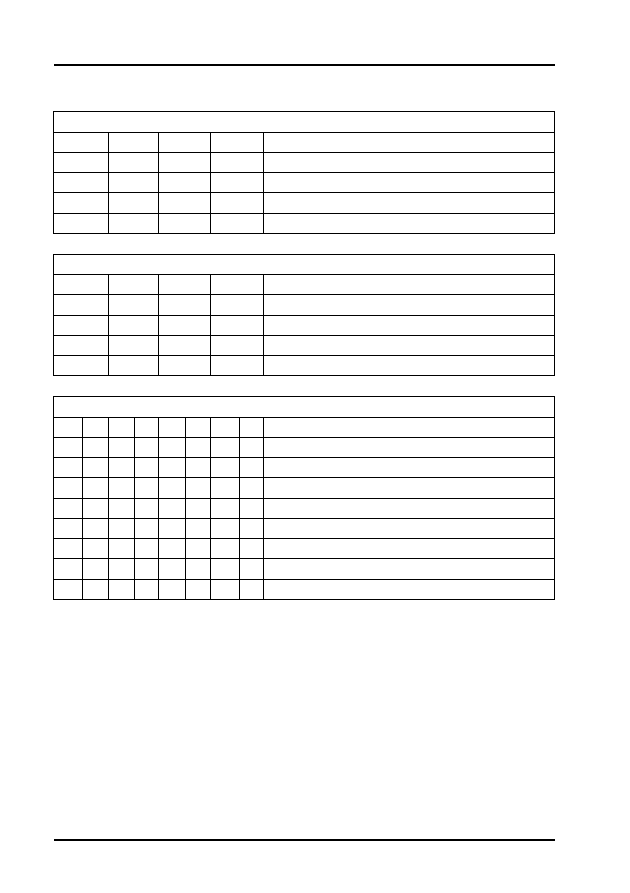
Audi, Seat, Skoda and Volkswagen
78
Table 57 - Group 66 Brake/Clutch Switch Monitor
Table 58 - Group 66 Cruise Control Switch Monitor
Table 59 - Group 86 Readiness Code
Relevant when '1' is displayed in the 4-digit blocks
X
X
X
X
Display group 66 - Line 2
1
Brake depressed (brake light switch)
1
Brake depressed (brake pedal switch)
1
Clutch depressed (AT: always 1)
1
Cruise control system operational (CCS)
Relevant when '1' is displayed in the 4-digit blocks
X
X
X
X
Display group 66 - Line 4
1
CCS sliding switch at off (switch locked)
1
CCS sliding switch at off (switch unlocked)
1
'SET' button depressed
1
CCS sliding switch at 'RES'
Relevant when '1' is displayed in the 8-digit blocks
X
X
X
X
X
X
X
X
Display group 86 - Line 1
0
Catalyst
0
Catalyst heating
0
EVAP system
0
Secondary air system
0
Air conditioner
0
Oxygen sensor
0
Oxygen sensor heating
0
EGR system

Audi, Seat, Skoda and Volkswagen
79
Engine Codes: ANB, APT, APU and ARG
Display
Group
Description
1
1. Engine speed.
2. Engine coolant temperature.
3. Lambda control (see note below).
4. Operating condition (for the relevance of this display line, see Table
60).
NOTE: Minus value indicates a weak mixture, positive value indicates a rich mixture.
2
1. Engine speed.
2. Engine load.
3. Injection duration.
4. Intake air mass.
3
1. Engine speed.
2. Intake air mass.
3. Throttle valve angle.
4. Ignition timing.
4
1. Engine speed.
2. ECU supply voltage.
3. Engine coolant temperature.
4. Intake air temperature.
5
1. Engine speed.
2. Engine load.
3. Vehicle speed.
4. Operating mode (idle, part load, etc.).
6
1. Engine speed
2. Engine load.
3. Intake air temperature.
4. Altitude correction factor.
10 Ignition
1. Engine speed.
2. Engine load.
3. Throttle valve angle.
4. Ignition timing.
14 Misfire
Recognition
(code: ANB)
1. Engine speed.
2. Engine load.
3. Misfire total.
4. Misfire recognition.
22 Knock
Control
1. Engine speed.
2. Engine load.
3. Retardation of ignition timing by knock control - cylinder 1.
4. Retardation of ignition timing by knock control - cylinder 2.

Audi, Seat, Skoda and Volkswagen
80
23 Knock
Control
1. Engine speed.
2. Engine load.
3. Retardation of ignition timing by knock control cylinder 3.
4. Retardation of ignition timing by knock control cylinder 4.
30 Lambda
Regulation
1. Pre-catalyst lambda regulation status (for the relevance of this
display line, see Table 61).
2. Post-catalyst lambda regulation status (for the relevance of this
display line, see Table 61).
3. Not allocated
4. Not allocated
32 Lambda
Regulation
1. Lambda learnt value at idling speed (additive) (see note below).
2. Lambda learnt value at part load (multiplicative) (see note below).
3. Not allocated
4. Not allocated
NOTE: A low value indicates that the engine is running too rich and therefore the ECU is
weakening the mixture.
A high value indicates that the engine is running too weak and therefore the ECU is
enriching the mixture
Additive: The effects of a fault (e.g. Intake air leak), will reduce as the engine speed
increases, so the injection period will be modified by a fixed amount. This amount is not
dependent on the basic injection duration period.
Multiplicative: The effects of a fault (e.g. Injector fault) will increase as engine speed
increases, so a multiplicative learnt value is a proportional change to the injection
duration. The change is dependent on the basic injection duration period.
33 Lambda
Regulation
1. Pre-catalyst lambda regulator.
2. Pre-catalyst oxygen sensor voltage.
3. Not allocated
4. Not allocated
34 Lambda
Regulation
(code: ANB)
1. Engine speed.
2. Catalyst temperature (see Note 1 below).
3. Pre-catalyst oxygen sensor cycle duration.
4. Result of pre-catalyst oxygen sensor age test (see Note 2 below).
NOTE 1: Calculated value from engine speed and load
NOTE 2: The ECU compares the adjustment frequency of the sensors' evaluation
circuitry with a stored specification. If the value is not reached, the text 'B1-P1 n/OK' is
displayed in line 4.
37 Lambda
Regulation
(code ANB)
1. Engine load.
2. Post-catalyst oxygen sensor voltage.
3. Pre-catalyst lambda regulation dwell period.
4. Test result.
41 Oxygen
sensor
heating
1. Pre-catalyst oxygen sensor heater resistance.
2. Pre-catalyst oxygen sensor heater status.
3. Post-catalyst oxygen sensor heater resistance.
4. Post-catalyst oxygen sensor heater status.

Audi, Seat, Skoda and Volkswagen
81
46 Catalyst
Diagnosis
(code ANB)
1. Engine speed.
2. Catalyst temperature.
3. Amplitude ratio.
4. Test result.
99 Lambda
Regulation
Operating
Conditions
1. Engine speed.
2. Engine coolant temperature.
3. Lambda regulator.
4. Operating mode.
50 Idle Speed
Regulation
1. Actual engine speed.
2. Specified engine speed.
3. A/C operating mode.
4. A/C compressor status.
54 Idling
Control
1. Engine speed.
2. Operating mode (idle, part load, etc.).
3. Accelerator pedal position (sensor 1).
4. Throttle valve angle (sensor 1).
55 Speed
Regulation
1. Engine speed.
2. Idling regulator.
3. Idling regulator learnt value.
4. Operating condition (for the relevance of this display line, see Table
62).
56 Speed
Regulation
1. Actual engine speed.
2. Specified engine speed.
3. Idling regulator.
4. Operating mode (for the relevance of this display line, see Table
63).
60 Electronic
Throttle
System
1. Throttle valve angle (sensor 1).
2. Throttle valve angle (sensor 2).
3. Learning step counter.
4. Adaptation condition.
62 Electronic
Throttle
System
1. Throttle valve angle (sensor 1).
2. Throttle valve angle (sensor 2).
3. Accelerator pedal position (sensor 1)
4. Accelerator pedal position (sensor 2).
62 Electronic
Throttle
System
kick-down
adaption
1. Throttle valve angle (sensor 1).
2. Throttle valve angle (sensor 2).
3. Accelerator pedal position.
4.

Audi, Seat, Skoda and Volkswagen
82
66 Cruise
Control
System
(CCS)
1. Actual vehicle speed.
2. Brake, clutch and CCS switch positions (for the relevance of this
display line, see Table 64).
3. Specified vehicle speed (last value stored by CCS).
4. Position of CCS controls switch (for the relevance of this display
line, see Table 65).
70 EVAP
System (code
ANB)
1. EVAP canister purge valve duty cycle.
2. Lambda regulation deviation during tank vent valve diagnosis.
3. Not allocated
4. Result of test.
77 Secondary
Air Injection
System (code
ANB)
1. Engine speed.
2. Engine coolant temperature.
3. Secondary air injection air mass
4. Result of test.
91 Camshaft
Adjustment
(non-turbo)
1. Engine speed.
2. Engine load.
3. Operating mode of camshaft adjustment.
4. Active camshaft adjustment angle.
95 Variable
Manifold
(non-turbo)
1. Engine speed.
2. Engine load.
3. Engine coolant temperature.
4. Status.
100
Readiness
Code (code
ANB)
1. Readiness code (for the relevance of this display line, see Table
66).
2. Engine coolant temperature.
3. Period since last engine start.
4. Diagnosis status.
114 Turbo
Charge
Pressure
Control
1. Specified engine load.
2. Specified engine load after correction (see note below).
3. Actual engine load.
4. Charge pressure control solenoid duty cycle.
NOTE: Reduced after knock control, altitude adaption and coolant temperature
regulation.
115 Turbo
Charge
Pressure
Control
1. Engine speed.
2. Engine load.
3. Specified turbo charge pressure.
4. Actual turbo charge pressure.
117 Turbo
Charge
Pressure
Control
1. Engine speed.
2. Accelerator pedal position (sensor 1).
3. Throttle valve angle (sensor 1).
4. Specified turbo charge pressure.
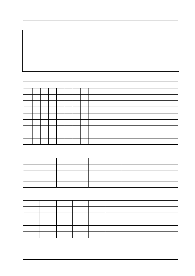
Audi, Seat, Skoda and Volkswagen
83
Table 60 - Group 1 Operating Condition
Table 61 - Group 30 Lambda Regulation Status
Table 62 - Group 55 Speed Regulation Operating Condition
118 Turbo
Charge
Pressure
Control
1. Engine speed.
2. Intake air temperature.
3. Turbo charge pressure control valve duty cycle.
4. Actual turbo charge pressure.
120 Traction
Control
1. Engine speed.
2. Specified engine load.
3. Actual engine load.
4. Status.
Relevant when '1' is displayed in the 8-digit blocks
X
X
X
X
X
X
X
X
Display group 1 - Line 4
1
Coolant temperature above 80°C
1
Speed below 2000 rpm
1
Throttle valve closed
1
Lambda regulation OK
1
Idle switch closed
1
A/C compressor switch off
1
Not assigned
1
No faults recognised
Relevant when '1' is displayed in the 3-digit blocks
X
X
X
Display group 30 - Lines 1 & 2
1
Lambda regulation active
1
Oxygen sensor operationally
ready
1
Oxygen sensor heating on
Relevant when '1' is displayed in the 5-digit blocks
X
X
X
X
X
Display group 55 - Line 4
1
A/C compressor switch on
1
Selected gear
1
A/C system switched on
X
Not relevant
1
Not relevant

Audi, Seat, Skoda and Volkswagen
84
Table 63 - Group 56 Speed Regulation Operating Mode
Table 64 - Group 66 Brake/Clutch Switch Monitor
Table 65 - Group 66 Cruise Control Switch Monitor
Relevant when '1' is displayed in the 5-digit blocks
X
X
X
X
X
Display group 56 - Line 4
1
A/C compressor switch on
1
Selected gear
1
A/C system switched on
X
Not relevant
1
Not relevant
Relevant when '1' is displayed in the 4-digit blocks
X
X
X
X
Display group 66 - Line 2
1
Brake depressed (brake light switch)
1
Brake depressed (brake pedal switch)
1
Clutch depressed (AT: always 1)
1
Cruise control system operational (CCS)
Relevant when '1' is displayed in the 4-digit blocks
X
X
X
X
Display group 66 - Line 4
1
CCS sliding switch at off (switch locked)
1
CCS sliding switch at off (switch unlocked)
1
'SET' button depressed
1
CCS sliding switch at 'RES'
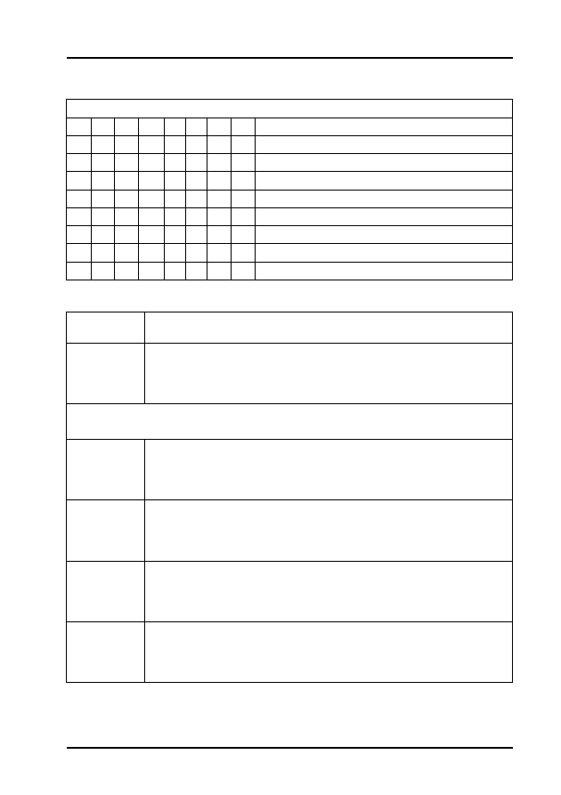
Audi, Seat, Skoda and Volkswagen
85
Table 66 - Group 100 Readiness Code
Engine Codes: APR and AQD
Relevant when '1' is displayed in the 8-digit blocks
X
X
X
X
X
X
X
X
Display group 100 - Line 1
0
Catalyst
0
Catalyst heating
0
EVAP system
0
Secondary air system
0
Air conditioner
0
Oxygen sensor
0
Oxygen sensor heating
0
EGR system
Display
Group
Description
1
1. Engine speed.
2. Engine coolant temperature.
3. Lambda regulator - Bank 1 (see note below).
4. Lambda regulator - Bank 2 (see note below).
NOTE: Bank 1 = cylinders 1, 2 and 3
Bank 2 = cylinders 4, 5 and 6
2
1. Engine speed.
2. Engine load.
3. Injection duration.
4. Intake air mass.
3
1. Engine speed.
2. Intake air mass.
3. Throttle valve angle (sensor 1).
4. Ignition timing.
4
1. Engine speed.
2. ECU supply voltage.
3. Engine coolant temperature.
4. Intake air temperature.
5
1. Engine speed.
2. Engine load.
3. Vehicle speed.
4. Operating mode (idle, part load).

Audi, Seat, Skoda and Volkswagen
86
6
1. Engine speed
2. Engine load.
3. Intake air temperature.
4. Altitude correction factor.
10 Ignition
1. Engine speed.
2. Engine load.
3. Throttle valve angle (sensor 1).
4. Ignition timing.
22 Knock
Control
1. Engine speed.
2. Engine load.
3. Retardation of ignition timing by knock control - cylinder 1.
4. Retardation of ignition timing by knock control - cylinder 2.
23 Knock
Control
1. Engine speed.
2. Engine load.
3. Retardation of ignition timing by knock control cylinder 3.
4. Retardation of ignition timing by knock control cylinder 4.
24 Knock
Control
1. Engine speed.
2. Engine load.
3. Retardation of ignition timing by knock control cylinder 5.
4. Retardation of ignition timing by knock control cylinder 6.
28 Knock
Control
1. Engine speed.
2. Engine load.
3. Engine coolant temperature.
4. Result of knock sensor test.
30 Lambda
Regulation
1. Oxygen sensor status - Bank 1 (for the relevance of this display line,
see Table 67).
2. Not allocated
3. Oxygen sensor status - Bank 2 (for the relevance of this display line,
see Table 67).
4. Not allocated
31 Oxygen
Sensor
Voltage
1. Oxygen sensor status - Bank 1.
2. Not allocated
3. Oxygen sensor status - Bank 2.
4. Not allocated.
32 Lambda
Learnt
Values
1. Idle speed lambda learnt values - Bank 1 (additive) (see note
below).
2. Part load lambda learnt values - Bank 1 (multiplicative) (see note
below).
3. Idle speed lambda learnt values - Bank 2 (additive) (see note
below).
4. Idle speed lambda learnt values - Bank 2 (multiplicative) (see note
below).

Audi, Seat, Skoda and Volkswagen
87
NOTE: A low value indicates that the engine is running too rich and therefore the ECU
is weakening the mixture.
A high value indicates that the engine is running too weak and therefore the ECU is
enriching the mixture.
Additive: The effects of a fault (e.g. Intake air leak), will reduce as the engine speed
increases, so the injection period will be modified by a fixed amount. This amount is not
dependent on the basic injection duration period.
Multiplicative: The effects of a fault (e.g. Injector fault) will increase as engine speed
increases, so a multiplicative learnt value is a proportional change to the injection
duration. The change is dependent on the basic injection duration period.
33 Lambda
Regulation
Values
1. Lambda regulation - Bank 1.
2. Oxygen sensor voltage - Bank 1.
3. Lambda regulation - Bank 2
4. Oxygen sensor voltage - Bank 2
99 Lambda
Regulation
1. Engine speed.
2. Engine coolant temperature.
3. Lambda regulator.
4. Lambda regulation operating mode.
50 Idle
Speed
Regulation
1. Engine speed.
2. Specified engine speed.
3. A/C system operating mode.
4. A/C compressor status.
54 Idle
Speed
Control
1. Engine speed.
2. Operating mode (idle, part load, etc.).
3. Accelerator pedal position - sensor 1.
4. Throttle valve angle - sensor 1.
55 Idle
Speed
Stabilisation
1. Engine speed.
2. Idling regulator.
3. Idle regulator learning value.
4. Operating mode (for the relevance of this display line, see Table
68).
56 Idle
Speed
Stabilisation
1. Engine speed.
2. Specified engine speed.
3. Idle regulator.
4. Operating mode (for the relevance of this display line, see Table
69).
60 Electronic
Throttle
System
1. Throttle valve angle - sensor 1.
2. Throttle valve angle - sensor 2.
3. Learning step counter.
4. Adaption condition.
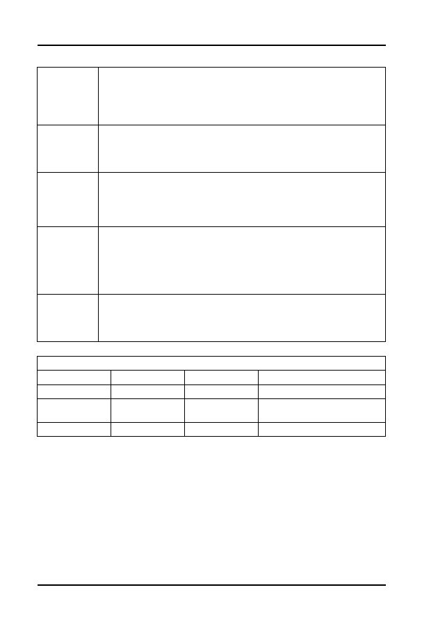
Audi, Seat, Skoda and Volkswagen
88
Table 67 - Group 30 Lambda Regulation
61 Electronic
Throttle
System
1. Engine speed.
2. ECU supply voltage.
3. Throttle valve angle - sensor 1.
4. Operating mode (for the relevance of this display line, see Table
70).
62 Electronic
Throttle
System
1. Throttle valve angle - sensor 1.
2. Throttle valve angle - sensor 2.
3. Accelerator pedal position - sensor 1.
4. Accelerator pedal position - sensor 2.
63 Electronic
Throttle
System - kick
down
adaption
1. Throttle valve angle - sensor 1.
2. Throttle valve angle - sensor 2.
3. Accelerator pedal position.
4. Operating mode.
66 Cruise
Control
System
(CCS)
1. Vehicle speed.
2. Brake, clutch and CCS switch positions (for the relevance of this
display line, see Table 71).
3. Specified road speed (last value stored by CCS).
4. Position of CCS control switch (for the relevance of this display line,
see Table 72).
120 Traction
Control
System
1. Engine speed.
2. Specified engine load.
3. Measured engine load
4. Status.
Relevant when '1' is displayed in the 3-digit blocks
X
X
X
Display group 30 - Lines 1 & 2
1
Lambda regulation active
1
Oxygen sensor operationally
ready
1
Oxygen sensor heating on
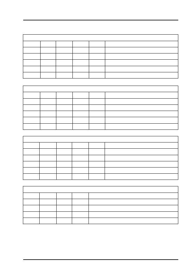
Audi, Seat, Skoda and Volkswagen
89
Table 68 - Group 55 Idle Speed Operating Mode
Table 69 - Group 56 Idle Speed Operating Mode
Table 70 - Group 61 Electronic Throttle Operating Mode
Table 71 - Group 66 Brake/Clutch Switch Monitor
Relevant when '1' is displayed in the 5-digit blocks
X
X
X
X
X
Display group 55 - Line 4
1
A/C compressor switch on
1
Selected gear
1
A/C system switched on
X
Not relevant
1
PAS pressure switch on
Relevant when '1' is displayed in the 5-digit blocks
X
X
X
X
X
Display group 55 - Line 4
1
A/C compressor switch on
1
Selected gear
1
A/C system switched on
X
Not relevant
1
PAS pressure switch on
Relevant when '1' is displayed in the 5-digit blocks
X
X
X
X
X
Display group 55 - Line 4
1
A/C compressor switch on
1
Selected gear
1
A/C system switched on
X
Not relevant
1
PAS pressure switch on
Relevant when '1' is displayed in the 4-digit blocks
X
X
X
X
Display group 66 - Line 2
1
Brake depressed (brake light switch)
1
Brake depressed (brake pedal switch)
1
Clutch depressed (AT: always 1)
1
Cruise control system operational (CCS)

Audi, Seat, Skoda and Volkswagen
90
Table 72 - Group 66 Cruise Control Switch Monitor
Engine Codes: AHL and ARM
Relevant when '1' is displayed in the 4-digit blocks
X
X
X
X
Display group 66 - Line 4
1
CCS sliding switch at off (switch locked)
1
CCS sliding switch at off (switch unlocked)
1
'SET' button depressed
1
CCS sliding switch at 'RES'
Display Group
Description
1
1. Engine speed.
2. Engine coolant temperature.
3. Oxygen sensor voltage.
4. Adjustment condition for matching throttle valve (for the
relevance of this display line, see Table 73).
2
1. Engine speed.
2. Intake air mass.
3. Vehicle speed.
4. Engine operating conditions (for the relevance of this display
line, see Table 74).
3
1. Engine speed.
2. Intake air mass.
3. Throttle valve angle.
4. Throttle valve positioner duty cycle.
4
1. Engine speed.
2. Intake air mass (engine load).
3. Injection duration.
4. Intake air mass.
5
1. Engine speed.
2. ECU supply voltage.
3. Engine coolant temperature.
4. Intake air temperature.
6 Altitude
Correction
1. Engine speed
2. Intake air mass.
3. Throttle valve angle.
4. Altitude correction factor.
7 Idling
Adjustment
1. Throttle valve angle.
2. Idling control learnt value (transmission in Neutral or Park).
3. Idling control learnt value (automatic transmission drive gear
selected).
4. Engine operating condition (for the relevance of this display
line, see Table 75).

Audi, Seat, Skoda and Volkswagen
91
8 Idling
Stabilisation
1. Actual engine speed.
2. Specified engine speed.
3. Idling control.
4. Intake air mass.
9 Idling Air
Requirements
1. Idling control.
2. Throttle valve control part operating status (for the relevance of
this display line, see Table 76).
3. Engine coolant temperature.
4. Engine speed.
10 Lambda
Regulation and
EVAP System
1. Lambda control.
2. Oxygen sensor voltage.
3. EVAP canister purge valve duty cycle.
4. Lambda correction factor whist tank venting is active.
11 Lambda
Learning Values
1. Injection duration.
2. Lambda learnt value at idle.
3. Lambda learnt value at part load.
4. Tank vent valve condition (for the relevance of this display line,
see Table 77).
12 Lambda
Control
1. Engine speed.
2. Intake air mass (engine load).
3. Lambda control.
4. Oxygen sensor voltage.
13 Fuel
Consumption
1. Engine speed.
2. Intake air mass (engine load).
3. Vehicle speed.
4. Fuel consumption.
14 Knock
Control
1. Retardation of ignition timing by knock control - cylinder 1.
2. Retardation of ignition timing by knock control - cylinder 2.
3. Retardation of ignition timing by knock control - cylinder 3.
4. Retardation of ignition timing by knock control - cylinder 4.
15 Knock
Control
1. Engine speed.
2. Intake air mass (engine load).
3. Retardation of ignition timing by knock control - cylinder 1.
4. Retardation of ignition timing by knock control - cylinder 2.
16 Knock
Control
1. Engine speed.
2. Intake air mass (engine load).
3. Retardation of ignition timing by knock control - cylinder 3.
4. Retardation of ignition timing by knock control - cylinder 4.
17 Knock
Control
1. Cylinder 1 knock sensor voltage.
2. Cylinder 2 knock sensor voltage.
3. Cylinder 3 knock sensor voltage.
4. Cylinder 4 knock sensor voltage.

Audi, Seat, Skoda and Volkswagen
92
18 Torque
Reduction
(automatic
transmission)
1. Engine speed.
2. Intake air mass (engine load).
3. Retardation of ignition timing for gearbox 'cut-in'.
4. Ignition timing.
19 Operating
Conditions
1. Engine speed.
2. Selector lever position (0=Neutral).
3. A/C system (0=off).
4. A/C compressor (0=off).
20 Lambda
Control
Operating
Conditions
1. Engine speed.
2. Intake air mass (engine load).
3. Engine coolant temperature.
4. Lambda control operating conditions (for the relevance of this
display line, see Table 78).
21 Throttle
Valve Control
part adaption
condition
1. Throttle valve control part operating condition (for the relevance
of this display line, see Table 79).
2. Throttle valve minimum position.
3. Throttle valve 'limp home' running position.
4. Throttle valve maximum position.
22 Position of
Camshaft in
relation to the
Crankshaft
1. Engine speed.
2. Intake air mass (engine load).
3. No. of teeth on the crank sender wheel when the Hall sensor
signal changes from - to + (see note below).
4. No. of teeth on the crank sender wheel when the Hall sensor
signal changes from + to - (see note below).
NOTE: The engine speed sensor on the crankshaft transmits both the engine speed
signal and a reference for crankshaft position. The reference signal is generated by a
gap in the sender wheel. The Hall sensor rotor ring on the camshaft has a 180°
division so that for half a camshaft revolution the window for the Hall sensor is
covered, and for the other half revolution the window is exposed. To synchronise the
components when starting, the ECU records the instant the Hall sensor rotor ring
begins to cover the window (signal changes from - to +) and the instant the window
begins to be exposed (signal changes from + to -). When the reference mark signal
from the crank sensor is detected, the ECU counts the number of teeth on the
crankshaft mounted sender wheel, as soon as it has counted between 26 an 30 teeth
after the reference gap, the signal from the Hall sensor should change from - to +.
After between 86 an 90 teeth, the Hall sensor signal should change from + to -.
98 Matching
Throttle Control
part
1. Throttle valve potentiometer voltage.
2. Throttle valve positioner potentiometer voltage.
3. Throttle control part operating condition (for the relevance of
this display line, see Table 80).
4. Throttle control part matching condition (for the relevance of this
display line, see Table 81).
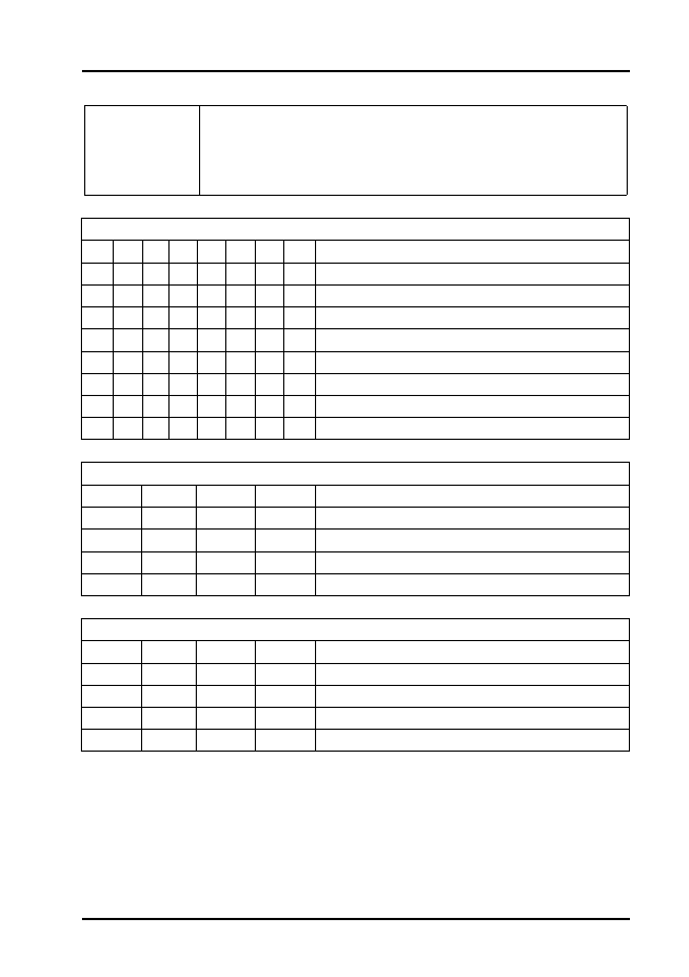
Audi, Seat, Skoda and Volkswagen
93
Table 73 - Group 1 Adjustment Condition
Table 74 - Group 2 Engine Operating Conditions
Table 75 - Group 7 Engine Operating Conditions
99 Lambda
Regulation
1. Engine speed.
2. Engine coolant temperature.
3. Lambda control.
4. Operating condition (for the relevance of this display line, see
Table 82).
Relevant when '1' is displayed in the 8-digit blocks
X
X
X
X
X
X
X
X
Display group 1 - Line 4
1
Coolant temperature below 80°C
1
Engine running
1
Throttle valve open
1
Fault in lambda control
1
Idle switch open
1
A/C compressor switch on
1
Signal from automatic gearbox
1
Fault recognised
Relevant when '1' is displayed in the 4-digit blocks
X
X
X
X
Display group 2 - Line 4
1
Full throttle
1
Part throttle
1
Idling
1
Overrun
Relevant when '1' is displayed in the 4-digit blocks
X
X
X
X
Display group 7 - Line 4
1
Full throttle
1
Part throttle
1
Idling
1
Overrun
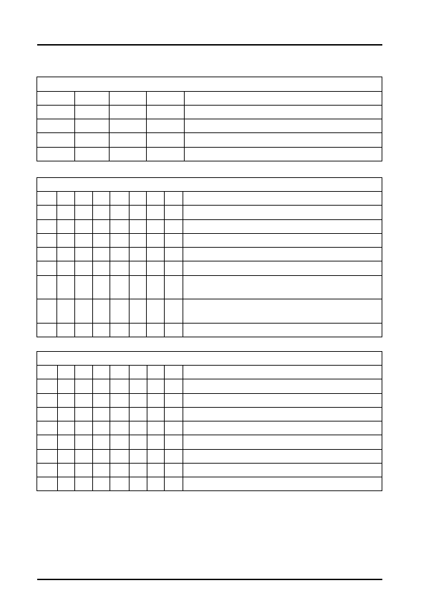
Audi, Seat, Skoda and Volkswagen
94
Table 76 - Group 9 Throttle Valve Operating Conditions
Table 77 - Group 11 Tank Vent Valve Condition
Table 78 - Group 20 Lambda Control Operating Conditions
Relevant when '1' is displayed in the 4-digit blocks
X
X
X
X
Display group 9 - Line 2
1
Idle switch open
1
Battery voltage below 8V
1
No current supply to throttle control part
1
Fault recognised
Relevant when '1' is displayed in the 8-digit blocks
X
X
X
X
X
X
X
X
Display group 11 - Line 4
1
Tank vent valve closed
1
Tank vent valve minimum operating level
1
Tank vent valve operating normally
1
Vapour content check via tank vent valve
1
Transition to tank vent valve closure
1
Transition to tank vent valve minimum operating
level
1
Transition to vapour content check via tank vent
valve
0
Not assigned
Relevant when '1' is displayed in the 8-digit blocks
X
X
X
X
X
X
X
X
Display group 20 - Line 4
1
Mixture status (1 = rich, 0 = lean)
1
Oxygen sensor functioning
1
Lambda control switched on
1
Lambda control at limit
1
Restricted operating mode
0
Not assigned
0
Not assigned
1
Fault recorded during diagnosis

Audi, Seat, Skoda and Volkswagen
95
Table 79 - Group 21 Throttle Valve Operating Condition
Table 80 - Group 98 Throttle Valve Operating Condition
Table 81 - Group 98 Throttle Valve Matching Condition
Table 82 - Group 99 Lambda Regulation Operating Conditions
Relevant when '1' is displayed in the 4-digit blocks
X
X
X
X
Display group 21 - Line 1
1
Idle switch open
1
Battery voltage below 8V
1
No current supply to throttle control part
1
Fault recognised
Relevant when '1' is displayed in the 4-digit blocks
X
X
X
X
Display group 21 - Line 1
1
Idle switch open
1
Battery voltage below 8V
1
No current supply to throttle control part
1
Fault recognised
Relevant when '1' is displayed in the 2-digit blocks
X
X
Display group 98 - Line 4
1
Throttle control part is being matched
1
Fault recognised
Relevant when '1' is displayed in the 8-digit blocks
X
X
X
X
X
X
X
X
Display group 20 - Line 4
1
Mixture status (1 = rich, 0 = lean)
1
Oxygen sensor functioning
1
Lambda control switched on
1
Lambda control at limit
1
Restricted operating mode
0
Not assigned
0
Not assigned
1
Fault recorded during diagnosis

Audi, Seat, Skoda and Volkswagen
96
Engine Codes: AGA, AJG, ALF and ALW
Display
Group
Description
1
1. Engine speed.
2. Engine coolant temperature.
3. Lambda control - bank 1.
4. Lambda control - bank 2.
2
1. Engine speed.
2. Engine load.
3. Average injection duration.
4. Intake air mass.
4 Intake Air
Temperature
at idle speed
1. Engine speed.
2. Battery voltage.
3. Engine coolant temperature.
4. Intake air temperature.
5 Vehicle
Speed
1. Engine speed.
2. Engine load.
3. Vehicle speed.
4. Engine operating status (part load, idle, etc.).
30 Oxygen
Sensor
1. Oxygen sensor status - bank 1.
2.
3. Oxygen sensor status - bank 2.
4. Not allocated.
32 Lambda
Learnt Values
1. Lambda learnt value at idle speed - bank 1 (additive) (see note
below).
2. Lambda learnt value at part throttle - bank 1 (multiplicative) (see
note below).
3. Lambda learnt value at idle speed - bank 2 (additive) (see note
below).
4. Lambda learnt value at part throttle - bank 2 (multiplicative) (see
note below).
NOTE: A low value indicates that the engine is running too rich and therefore the ECU
is weakening the mixture.
A high value indicates that the engine is running too weak and therefore the ECU is
enriching the mixture.
Additive: The effects of a fault (e.g. Intake air leak), will reduce as the engine speed
increases, so the injection period will be modified by a fixed amount. This amount is not
dependent on the basic injection duration period.
Multiplicative: The effects of a fault (e.g. Injector fault) will increase as engine speed
increases, so a multiplicative learnt value is a proportional change to the injection
duration. The change is dependent on the basic injection duration period.

Audi, Seat, Skoda and Volkswagen
97
33 Lambda
Regulation at
idle speed
1. Lambda control - bank 1.
2. Oxygen sensor voltage - bank 1.
3. Lambda control - bank 2.
4. Oxygen sensor voltage - bank 2.
50 Signals to
Engine ECM
1. Engine speed.
2. Specified engine speed.
3. A/C status.
4. A/C compressor status.
54 Idle Speed
Switch
1. Engine speed.
2. Engine operating condition (idle, part load, etc.).
3. Throttle valve angle.
4. Throttle valve positioner angle.
56
1. Engine speed.
2. Specified engine speed.
3. Intake air mass.
4. Operating conditions (for the relevance of this display line, see
Table 83).
90 Camshaft
Timing
Control
1. Engine speed.
2. Camshaft timing control status.
3. Feedback signal for adjustment - bank 1.
4. Feedback signal for adjustment - bank 2.
93 Hall
Senders
1. Engine speed.
2. Engine load.
3. Phase position - bank 1.
4. Phase position - bank 2.
95 Intake
Manifold
Change-over
1. Engine speed.
2. Engine load.
3. Engine coolant temperature.
4. Intake manifold change-over status (see note below).
NOTE: Intake manifold change-over should occur at approximately 4500 rpm.
98 Throttle
Control part
adaption
1. Throttle valve angle sensor voltage.
2. Idle speed positioner voltage.
3. Engine operating status (idle, part load, etc.).
4. Adaption status.
122 Torque
Reduction
during
Gearshift
1. Engine speed.
2. Specified gearbox torque.
3. Engine torque.
4. Ignition timing reduction status.

Audi, Seat, Skoda and Volkswagen
98
Table 83 - Group 56 Operating Conditions
Relevant when '1' is displayed in the 4-digit blocks
X
X
X
X
Display group 56 - Line 4
0
0 = A/C compressor off
1 = A/C compressor on
0
Gear selector position:
0 = P or N
1 = 2, 3, 4, R or D
0
Maximum hot/cold air output
0
Always 0
Wyszukiwarka
Podobne podstrony:
Opis Grup Silnika Silniki ABZ AEW AKG AKJ AHC AKH
Opis Grup Silnika Silniki AGA AJG ALF ALW
Opis grup silnika 2 8 ACK 2
Opis grup silnika 2 8 ACK 1
Adaptacja przepustnicy w silnikach VAG
BLOKI POMIAROWE SILNIKA Vag Com PL(1)
Opis wybranych bloków pomiarowych silnika VAG VCDS [ENG]
cat da 12t 2008 en Silniki
Silnik BAEL i LFS pomiar wartości Bloku VAG
Silnik AFB pomiar wartości Bloku VAG
EN VAG 1551 1 9 TDI diagnostics(1)
Opisy kanałów VAG
Silnik AKN pomiar wartości Bloku VAG
więcej podobnych podstron