
Renewable Energy 33 (2008) 77–87
Simulation, construction and testing of a two-cylinder solar Stirling
engine powered by a flat-plate solar collector without regenerator
Ali Reza Tavakolpour
a,
, Ali Zomorodian
a
, Ali Akbar Golneshan
b
a
Department of Mechanics of Farm Machinery Engineering, Shiraz University, Shiraz, Iran
b
Department of Mechanical Engineering, Shiraz University, Shiraz, Iran
Received 7 October 2006; accepted 3 March 2007
Available online 24 April 2007
Abstract
In this research, a gamma-type, low-temperature differential (LTD) solar Stirling engine with two cylinders was modeled, constructed
and primarily tested. A flat-plate solar collector was employed as an in-built heat source, thus the system design was based on a
temperature difference of 80 1C. The principles of thermodynamics as well as Schmidt theory were adapted to use for modeling the
engine. To simulate the system some computer programs were written to analyze the models and the optimized parameters of the engine
design were determined. The optimized compression ratio was computed to be 12.5 for solar application according to the mean collector
temperature of 100 1C and sink temperature of 20 1C. The corresponding theoretical efficiency of the engine for the mentioned designed
parameters was calculated to be 0.012 for zero regenerator efficiency. Proposed engine dimensions are as follows: power piston stroke
0.044 m, power piston diameter 0.13 m, displacer stroke 0.055 m and the displacer diameter 0.41 m. Finally, the engine was tested. The
results indicated that at mean collector temperature of 110 1C and sink temperature of 25 1C, the engine produced a maximum brake
power of 0.27 W at 14 rpm. The mean engine speed was about 30 rpm at solar radiation intensity of 900 W/m
2
and without load. The
indicated power was computed to be 1.2 W at 30 rpm.
r
2007 Elsevier Ltd. All rights reserved.
Keywords: Solar energy; Stirling engine; Flat-plate solar collector
1. Introduction
In view of energy management, solar energy is one of the
most important renewable and non-depletable energy
sources for generating power. There are several methods
for converting solar heat into mechanical energy. One of
these methods that theoretically associated with maximum
efficiency is Stirling engine (or hot air engine). Stirling
engine is a simple kind of external combustion engine. It is
an old concept first proposed by Robert Stirling in 1816
(UK, patent no. 4081). Engines based upon his invention
were built in many forms and sizes. These engines offer the
possibly of a high-efficiency engine with lower exhausted
emissions in comparison with the internal combustion
engine. Hot air engines are clean and efficient and ran
almost silently on any combustible material such as field
waste and biomass.
In 1970 and 1980s a huge amount of researches were
conducted on Stirling engine for automobiles by companies
such as General Motors and Ford . The main drawback is,
the Stirling engine tends to run at a constant power setting
that is not proper for automobiles. But this characteristic is
perfect for applications such as water pumping. Studies
about high-temperature Stirling engines have been exten-
sively reported.
In most models, the engines operate with a heater and
cooler temperature about 923 and 338 K, respectively
The thermal limit for the operation of high-temperature
Stirling engines depends on the material used for its
construction. Engine efficiency ranges from about 30–40%
resulting in a typical temperature range of 923–1073 K, and
normal operating speed range is from 2000 to 4000 rpm
On the other hand, the low-temperature differential (LTD)
Stirling engine is a type of Stirling engine that can operate
ARTICLE IN PRESS
www.elsevier.com/locate/renene
0960-1481/$ - see front matter r 2007 Elsevier Ltd. All rights reserved.
doi:
Corresponding author. Tel.: +989173147706.
E-mail address:

with relatively small temperature difference between hot
and cold ends of the displacer cylinder
. The efficiency of
a LTD Stirling engine is low in comparison with the high-
temperature Stirling engines but it can be acceptable
due to the availability of many low-temperature heat
sources including solar energy which is inexpensive
and safe. LTD engines may be of two designs. The first
one uses single-crank operation where only the power
piston is connected to the flywheel, called Ringbom engine.
A short, large-diameter displacer rod in a precise-machined
fitted guide has been used to replace the displacer
connecting rod
. The other design is called a kinematic
engine, where both the displacer and the power piston are
connected to the flywheel through the cranks of the
crankshaft
. Large amount of studies on LTD Stirling
engines have been done during the recent century. Some of
them are as follows:
Kolin
tested a number of LTD Stirling engines, over a
period of many years. In 1983, he presented a model that
worked on a temperature difference between the hot and
cold ends of the displacer cylinder as low as 15 1C.
Senft
made an in-depth study of the Ringbom engine
and its derivatives, including the LTD engine. His research
in LTD Stirling engines resulted in a most interesting
engine which had an ultra-low temperature difference of
0.5 1C. It seems difficult to create any advancement better
than this result. Senft’s work in 1991
, showing the
principle motivation for using Stirling and general heat
engines, developed an engine operating with a temperature
difference of 2 1C or lower.
In 1993, Senft
described the design and testing of a
small LTD Ringbom Stirling engine powered by a 601
conical reflector. He reported that the tested 601 conical
reflector, producing hot end temperature of 93 1C under
running conditions, worked very well.
In 1997, Iwomoto et al.
compared the performance of
a LTD Stirling engine with a high-temperature differential
Stirling engine. Finally, they concluded that the LTD
Stirling engine efficiency at its rated speed was approxi-
mately 50% of the Carnot efficiency.
In 2005, Kongtragool and Wongwises
investigated
theoretically the power output of the gamma-configuration
LTD Stirling engine. In this work, the power calculation
was studied and discussed.
In 2005, Kongtragool and Wongwises
presented the
optimum absorber temperature of a once reflecting full-
conical reflector for a LTD Stirling engine and a
mathematical model for the overall efficiency of a solar-
powered Stirling engine was developed.
In 2006, Kongtragool and Wongwises
designed and
constructed two single-acting, twin-power piston and four-
power piston gamma-configuration LTD Stirling engines
with heater temperature of about 589–771 K. The tested
engines were equipped with regenerator to increase the
thermal efficiency.
Solar energy is a proper heat source for LTD Stirling
engine. Solar collectors as a special kind of heat exchangers
are usually employed to convert the solar radiation
into thermal energy. If a hot air engine is equipped
with a concentrated solar collector as a heat source, the
working temperature would be high and heat efficiency
would be effectively improved. But this system always
has to trace the direction of sun in the sky. The tracer
is a complex system and can waste part of the energy.
Flat-plate solar collectors need no tracer system and
can absorb diffused solar energy radiation as well. As
ARTICLE IN PRESS
Nomenclature
h
convective heat transfer coefficient
P
instantaneous pressure
m
gas mass
k
constant
V
volume
T
temperature
Q
heat
r
gas constant
S
exchanger plate area
W
work
x
working piston position
y
displacer position
D
difference
g
gas heat capacity ratio
Z
efficiency
n
frequency
s
x
dead space volume ratio ¼ (V
xds
/V
d
)
x
compression ratio ¼ (V
d
/V
p
) ¼ (S
d
y
0
)/(S
p
x
0
)
t
internal temperature ratio ¼ (T
h
/T
c
)
j
phase angle
a
displacer crank angle
b
power piston crank angle ¼ (ja)
Subscripts and superscripts
C
cold outer space/plate
c
cold inner space
0
reference parameter
d
displacer
ds
dead space
H
hot outer space/plate
h
hot inner space
loss
heat loss
p
working piston
reg
regenerator
*
dimensionless
**
dimensionless
0
isothermal process
pt
point
A.R. Tavakolpour et al. / Renewable Energy 33 (2008) 77–87
78
described above there is no published paper on experi-
mental results of the kinematic LTD solar Stirling engine
powered by a flat-plate solar collector without regenerator.
In this research, the simulation, construction and testing of
a solar LTD Stirling engine with flat plate solar collector as
an in-built heat source and without application of the
regenerator were investigated.
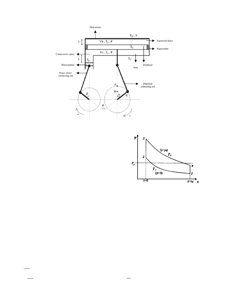
2. Mathematical model
A schematic sketch of a general LTD Stirling engine with
gamma configuration is shown in
. The Stirling cycle
is composed of two isothermal and two isochoric processes
(
). The procedures of finite dimension thermody-
namics were employed to calculate the optimized compres-
sion ratio according to the guidelines of Pierre Rochelle
. An optimization process, with work or efficiency as
the objective function, is investigated. In the following
description, the classical Schmidt assumption will be used
except for the finite heat transfer between the working gas
and the exchanger plates.
The gas mass content inside the engine is expressed by
the sum of gas mass contents in the expansion and
compression spaces together with the gas mass inside the
regenerator:
m ¼ m
c
þ
m
h
þ
m
reg
¼
P
rT
c
xS
p
þ ð
y
0
yÞS
d
þ
V
cds
þ
P
rT
h
yS
d
þ
V
hds
½
,
ð
1Þ
where y
0
is the complete stroke of the displacer piston, P is
the instantaneous pressure, m
reg
is the mass of the gas
inside the regenerator, V
hds
and V
cds
are the dead space
volumes on the hot and cold sides. Since this research has
been devoted to design a LTD solar Stirling engine without
regenerator, thus m
reg
was assumed to be zero in Eq. (1).
Moreover, in the LTD Stirling engine, if a regenerator had
been employed for improving the engine efficiency, the
value of m
reg
would have been negligible compared to
(m
c
+m
h
). This can be easily concluded form
according to the large volume of expansion and compres-
sion spaces in comparison with the small unavoidable dead
volume of the regenerator.
To reduce the number of variables involved in the problem,
dimensionless descriptions are defined as follows
:
P
¼
P
P
0
,
(2)
ARTICLE IN PRESS
Fig. 1. A general type of LTD Stirling engine with gamma-configuration.
Fig. 2. Ideal Stirling cycle.
A.R. Tavakolpour et al. / Renewable Energy 33 (2008) 77–87
79

x
¼
x
x
0
,
(3)
y
¼
y
y
0
,
(4)
where x
0
is the complete stroke of the power piston. The
reference mass m
0
and the dimensionless mass m
are defined
as follows:
m
0
¼
P
0
V
p
rT
c
,
(5)
m
¼
m
m
0
¼
P
x
þ ð
1 y
Þ
x þ xs
c
½
þ
1
t
y
x þ xs
h
½
.
(6)
Assuming the same dead space volumes s ¼ s
h
¼
s
c
and
letting A ¼ xð1 þ 2sÞ and B ¼ xðð1=tÞ 1Þ. Substituting A,
B and s in Eq. (6):
m
¼
P
x
þ
A þ Bðy
þ
sÞ
½
.
(7)
Other dimensionless descriptions are as follows:
P
n
ð
x
n
; y
n
Þ ¼
m
n
x
n
þ
A þ Bðy
n
þ
sÞ
,
(8)
m
n
h
ð
x
n
; y
n
Þ ¼
m
h
m
0
¼
m
n
xðy
n
þ
sÞ
t x
n
þ
A þ Bðy
n
þ
sÞ
½
,
(9)
m
n
h max
¼
m
n
h
ð
0; 1Þ ¼ m
n
xð1 þ sÞ
t A þ Bð1 þ sÞ
½
,
(10)
m
n
h min
¼
m
n
h
ð
1; 0Þ ¼ m
n
xs
t 1 þ A þ Bs
½
.
(11)
The dimensionless mass transfer Dm
n
between the volumes
is defined as
Dm
n
¼
m
n
h max
m
n
h min
¼
m
n
x
t
ð
1 þ A þ sÞ
A þ Bð1 þ sÞ
½
1 þ A þ Bs
½
.
ð
12Þ
To get the energy balance of the cycle, the dimensionless
work W
n
and transferred heats during the isothermal
processes are expressed as
W
n
¼
W
P
0
V
p
¼
1
P
0
S
P
x
0
I
PS
p
dx ¼
I
P
n
dx
n
,
(13)
Q
0
c
¼
1
P
0
V
p
I
P dV
c
¼
I
P
n
ð
dx
n
x dy
n
Þ
,
(14)
where V
c
¼
xS
p
þ ð
y
0
yÞS
d
þ
V
cds
.
Q
0
h
¼
1
P
0
V
p
I
P dV
h
¼
x
I
P
n
dy
n
,
(15)
where V
h
¼
yS
d
þ
V
hds
.
Solving Eqs. (13)–(15), we obtain
W
n
¼
I
P
n
dx
n
¼
Z
pt2
pt1
P
n
ð
x
n
; 0Þ dx
n
þ
Z
pt4
pt3
P
n
ð
x
n
; 1Þ dx
n
¼
m
n
Z
0
1
dx
n
x
n
þ
A þ Bs
þ
Z
1
0
dx
n
x
n
þ
A þ Bð1 þ sÞ
¼
m
n
lnðZÞ,
ð
16Þ
where
Z ¼ Zðx; s; tÞ ¼
1 þ ð1=A þ Bðs þ 1ÞÞ
1 þ ð1=A þ BsÞ
,
Q
0
h
¼
m
n
x
B
ln ðZÞ,
(17)
Q
0
c
¼
m
n
t
x
B
ln ðZÞ.
(18)
To calculate the total heat absorbed by the working
gas at the heat source, the heat lost in the regenerator is
added to the transferred heat during isothermal process
Q
reg
¼
Dm
r
g 1
ð
T
h
T
c
Þ
¼
P
0
V
p
Dm
m
0
1
g 1
ð
t 1Þ,
ð
19Þ
Q
loss
¼
Q
reg
ð
1 Z
reg
Þ
,
(20)
Q
n
loss
¼
Q
loss
P
0
V
P
¼
Dm
n
ð
t 1Þ
1 Z
reg
g 1
¼
m
n
Gk
reg
,
(21)
where
k
reg
¼
1 Z
reg
g 1
and
G ¼ Gðx; s; tÞ ¼
Bð1 þ A þ sÞ
½
A þ Bð1 þ sÞ½1 þ A þ Bs
.
The total heat absorbed by the working gas at the hot
source and the total heat rejected to the cold sink are as
follows:
Q
n
h
¼
Q
0
h
þ
Q
n
loss
¼
m
n
ðð
1=tÞ 1Þ
ln ðZÞ m
n
Gk
reg
¼
m
n
ln ðZÞ
ð
1=tÞ 1
Gk
reg
,
ð
22Þ
Q
n
c
¼
Q
0
c
Q
n
loss
¼
m
n
ln ðZÞ
tðð1=tÞ 1Þ
þ
m
n
Gk
reg
¼
m
n
ln ðZÞ
tðð1=tÞ 1Þ
þ
Gk
reg
.
ð
23Þ
ARTICLE IN PRESS
A.R. Tavakolpour et al. / Renewable Energy 33 (2008) 77–87
80

Finally, the efficiency of the engine can be calculated as
Z ¼
W
n
Q
n
h
¼
ln ðZÞ
ð
t lnðZÞ=ð1 tÞÞ þ k
reg
G
¼
t 1
t þ k
reg
ð
1 tÞðG= ln ðZÞÞ
.
ð
24Þ
The internal working gas temperature at expansion space
is less than the temperature of the solar absorber and the
air temperature inside the compression space is more than
the cold sink. To calculate the real temperature of the
working fluid inside the cylinder, heat transfer equations
are used as follows
Q
c
¼
hS
d
n
ð
T
C
T
c
Þ ¼
hS
d
n
T
C
1
T
c
T
C
,
(25)
Q
n
c
¼
Q
c
P
0
V
p
¼
hS
d
T
H
nP
0
V
p
T
C
T
H
1
T
c
T
C
¼
Nx
T
C
T
H
1
T
c
T
C
,
(26)
where
N ¼
hS
d
T
H
nP
0
S
d
y
0
¼
hT
H
nP
0
y
0
,
Q
h
¼
hS
d
n
ð
T
H
T
h
Þ ¼
hS
d
n
T
H
1
T
h
T
H
,
(27)
Q
n
h
¼
Q
h
P
0
V
p
¼
hS
d
nP
0
V
p
ð
T
H
T
h
Þ ¼
Nx 1
T
h
T
H
.
(28)
T
c
can be determined from Eqs. (23) and (26):
T
c
¼
T
C
m
n
T
H
Nx
ln ðZÞ
tðð1=tÞ 1Þ
þ
Gk
reg
¼
T
H
T
C
T
H
m
n
ln ðZÞ
NB
1
t
þ
1
t
1
k
reg
G
lnðZÞ
.
ð
29Þ
T
h
can be determined from Eqs. (22) and (28):
T
h
¼
T
H
m
n
T
H
Nx
ln ðZÞ
ð
1=tÞ 1
k
reg
G
¼
T
H
1 m
n
ln ðZÞ
NB
1 k
reg
1
t
1
G
lnðZÞ
.
ð
30Þ
From Eqs. (29) and (30), the internal temperature ratio t
can be obtained:
t ¼
T
h
T
c
¼
1 I 1 ðð1=tÞ 1ÞH
ð
T
C
=T
H
Þ
I ð1=tÞ þ ðð1=tÞ 1ÞH
,
(31)
where H ¼ Hðk
reg
; x; t; sÞ ¼ k
reg
ð
G= ln ðZÞÞ and I ¼ I ðm
n
;
N; x; s; tÞ ¼ m
n
ð
ln ðZÞ=NBÞ.
From Eq. (31):
1
t
t
2
T
C
T
H
þ
IH
t 2I þ 1
½
IH
¼
0.
(32)
If T
c
and T
h
assumed to be close together approximately,
then t
E1 and it results that m
n
ffi
1 þ A, Z ffi 1
ð
B=ðAð1 þ AÞÞÞ, ln ðZÞ ffi ðB=ðAð1 þ AÞÞÞ, G ffi ððBð1 þ
Aþ sÞÞ=ðAð1 þ AÞÞÞ, H ffi k
reg
ð
1 þ A þ sÞ, I ffi ðm
n
=NÞ
ð
1=ðAð1 þ AÞÞÞ and IHffim
*
(k
reg
/N)(((1+A+s))/(A(1+A)).
Thus H and I are independent of t
. The root of
Eq. (32) is
t ¼
ð
I þ
1
2
Þ
1 þ
ffiffiffiffiffiffiffiffiffiffiffiffiffiffiffiffiffiffiffiffiffiffiffiffiffiffiffiffiffiffiffiffiffiffiffiffiffiffiffiffiffiffiffiffiffiffiffiffiffiffiffiffiffiffiffiffiffiffiffiffiffiffiffiffiffiffiffiffiffi
1 þ ½IHððT
C
=T
H
Þ þ
IHÞ=ðI þ
1
2
Þ
2
q
ð
T
C
=T
H
Þ þ
IH
.
(33)
Reintroducing the real value of t from Eq. (33) into the
expression of W
n
and Z:
Z ¼
t 1
t þ k
reg
ð
1 tÞðG= ln ðZÞÞ
¼
t 1
t þ ð1 tÞH
ffi
t 1
t ð1 tÞk
reg
ð
1 þ A þ sÞ
,
ð
34Þ
W
n
¼ m
n
ln ðZÞ ffi m
n
B
Að1 þ AÞ
¼
1 ð1=tÞ
m
n
ð
1 þ 2sÞ 1 þ xð1 þ 2sÞ
½
.
ð
35Þ
The dimensionless work W
n
is reduced relative to the
working piston swept volume but for the users a preferred
reference volume is the overall volume, related to the
engine bulk. This is equal to the working volume plus the
displacer swept volume added to the dead space volumes.
Then a new dimensionless work will be defined as
W
nn
¼
W
j
j
P
0
ð
V
P
þ
V
d
þ
2V
ds
Þ
¼
W
n
1 þ xð1 þ 2sÞ
.
(36)
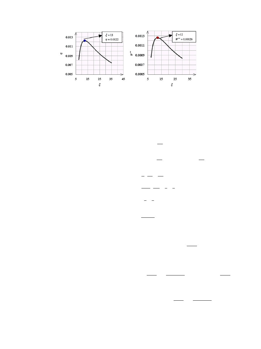
2.1. Optimized compression ratio
The first optimization goal concerning LTD Stirling
engines was to determine the optimum compression ratio x.
For given values of the parameters in
, the
compression ratio was incremented to find the optimum
value of x corresponding to maximum values of Z and W
nn
.
This was done by a computer program to determine the
optimized compression ratio (
).
In this research, an effort was devoted to design a solar
Stirling engine powered by a flat plate solar collector
ARTICLE IN PRESS
Table 1
Reference parameters
T
H
(K)
T
C
(K)
P
0
(pa)
s
n (rev s
1
)
h (W m
2
K
1
)
y
0
(mm)
g
Z
reg
373
293
100 000
0.1
0.5
10
55
1.4
0
A.R. Tavakolpour et al. / Renewable Energy 33 (2008) 77–87
81
without regenerator. The practical temperature of a
flat-plat solar collector is around 100 1C or more.
Therefore TH selected to be 100 1C and T
C
assumed to
be about the wet bulb temperature of the environment.
Since the regeneration process was ignored in this study,
Z
reg
¼
0. The convective heat transfer coefficient h,
assumed to be 10 W m
2
K
1
on both cold and hot
plates
.
It can be seen in
, there are optimum values of the
compression ratio. The optimized compression ratio
assumed to be 12.5 to maximize the secondary work and
efficiency.
2.2. Internal temperature of expansion space and
compression space
Substituting the optimized compression ratio and para-
meters of
and Eq. (33) into Eqs. (29) and (30), the
internal temperature of expansion and compression spaces
were computed. A computer program was written to solve
the equations. The corresponding values of T
h
and T
c
were
calculated as follows:
T
h
¼
337 K;
T
c
¼
328 K.
2.3. Schmidt theory
The Schmidt theory is one of the isothermal calculation
methods for Stirling engines. This theory provides for
harmonic motion of the reciprocating elements but retains
the major assumptions of isothermal compression and
expansion and of perfect regeneration. It, thus, retains
highly idealized, but is certainly more realistic than the
ideal Stirling cycle
. The assumption of simple-harmonic
volume variation permits pressure, P, to be expressed as a
function of crank angle, a, and leads to closed form
solutions for work per cycle
. The Schmidt formula may
be shown in various forms depending on the notations used
and can be arranged for gamma-configuration Stirling
engines
. Since the internal temperatures of expansion
and compression spaces, considering the proposed model,
were calculated in Section 2.2, the Schmidt theory with all
its related assumptions can be employed to determine
the theoretical output work and optimized phase angle
of the engine. According to the mechanical configura-
tion shown in
, the Schmidt formula can be arranged
as follows:
V
h
¼
V
hds
þ
V
d
2
ð
1 cos ðaÞÞ,
(37)
V
c
¼
V
cds
þ
V
p
2
ð
1 cos ða jÞÞ þ
V
d
2
ð
1 þ cos ðaÞÞ,
(38)
m ¼
P
r
V
c
T
c
þ
V
h
T
h
¼
PV
d
2rT
c
2s
h
t
þ
1
t
1
t
cos ðaÞ þ 2s
c
þ
1
x
1
x
cosða jÞ þ cos ðaÞ þ 1
,
ð
39Þ
P ¼
2mrT
c
V
d
F ðaÞ
,
(40)
where
F(a) ¼ (2s
h
/t)+(1/t)(1/t) cos(a)+2s
c
+(1/x)
(1/x) cos (aj)+ cos(a)+1.
W
h
¼
I
P dV
h
¼
mrT
c
Z
2p
0
sinðaÞ
F ðaÞ
da,
(41)
W
c
¼
I
P dV
c
¼
mrT
c
x
Z
2p
0
sinða jÞ
F ðaÞ
da
mrT
c
Z
2p
0
sinðaÞ
F ðaÞ
da
,
ð
42Þ
W
total
¼
W
h
þ
W
c
¼
mrT
c
x
Z
2p
0
sinða jÞ
F ðaÞ
da.
(43)
W
total
is the total work done per cycle. Using the results of
Section 2.2 and the information of
, the total work
done per cycle and the optimized phase angle can be
evaluated.
ARTICLE IN PRESS
Fig. 3. Efficiency and dimensionless secondary work versus compression ratio.
A.R. Tavakolpour et al. / Renewable Energy 33 (2008) 77–87
82
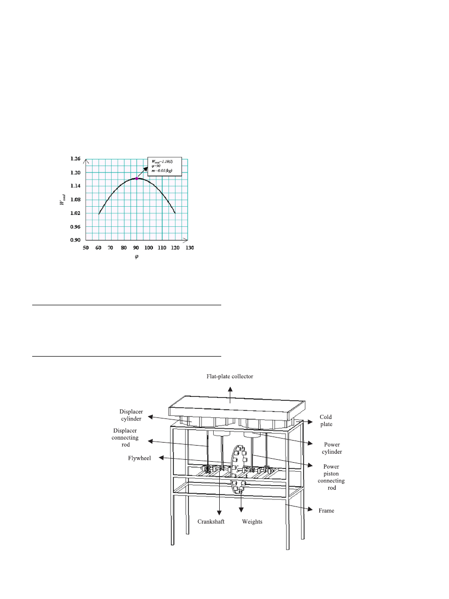
2.4. Total work done per cycle and optimized phase angle
A computer program was written to analyze the Eq. (43)
and plot the total work done per cycle as a function of
phase angle to calculate the optimum phase angle and total
work (
In this research, the engine was designed with two
cylinders,
so
the
total
work
done
per
cycle
is
2 1.18 ¼ 2.36 (J) theoretically without any regeneration
process.
3. Engine design and construction
Main engine design parameters are shown in
according to mathematical model. The schematic diagram
of the engine was shown in
. It is designed with two
separate cylinders and Gamma-configuration arrangement.
The power cylinders were made of a steel pipe and the
power pistons were made of an aluminum bar. The power
pistons were turned to match the power cylinder bores. The
clearance between the power piston and power cylinder
was 0.01 mm 15 mm thick Teflon pan was used to
construct the power piston connecting rod. The solar
absorber and the cold plate were made of 3 mm thick
aluminum plates. The crank shaft was made of 12 mm thick
steel shaft with eight Teflon cranks and crank pins. The
crank shaft was supported by six self-align ball bearings
that were located inside six wooden casing. The flywheel
was attached to the middle part of the crankshaft. The
flywheel was constructed form 15 mm thick Teflon pan
with several 0.14 kg steel dead weights attached around it
to decrease the speed fluctuations.
4. Measurement apparatus
The testing facilities are shown in
. Since the engine
speed was low, an accurate photo tachometer with
70.1 rpm accuracy was used to measure the engine speed.
Cooling water was used in the cold sink. To measure the
temperatures of the absorber and cold sink, some SMT-160
thermal sensors were attached to the aluminum plates of
heat exchangers. The accuracy of the temperature mea-
surement was
70.5 1C. To have a wide range of collector
temperature, a flat reflector was attached to the wooden
ARTICLE IN PRESS
Fig. 4. Total work done per cycle versus phase angle.
Table 2
Design parameters
Displacer
Bore stroke (m)
0.41 0.055
Power piston
Bore stroke (m)
0.13 0.044
Phase angle
901
Flat-plate collector dimensions (m)
1 0.5
Fig. 5. Solid model of the LTD solar Stirling engine without regenerator.
A.R. Tavakolpour et al. / Renewable Energy 33 (2008) 77–87
83
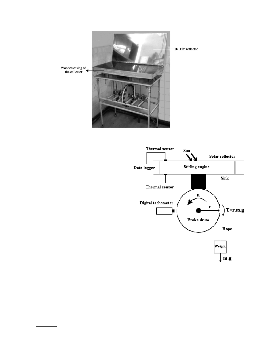
casing of the collector to enhance the solar energy intensity
on the absorber plate of the collector (
The solar intensity radiation was measured and recorded
by a Casella solarimeter every 5 min (0–2000 W m
2
,
71 mmv W m
2
).
Keeping in mind that generally the rope brake dynam-
ometer with a spring balance and loading weights is used to
measure the engine torque at different engine speed and the
engine torque can be determined from the difference of spring
balance reading and loading weight. Since the speed of the
LTD solar Stirling engine is clearly low compared to the speed
of internal combustion engines, an attempt has been made to
employ another dynamic method for evaluating the torque
and brake power of this low-speed LTD Stirling engine. Some
weights, a rope and a brake drum have been used to measure
the engine torque and the brake power (
). The weights
were hanged around the rotary brake drum attached to
crankshaft through the rope and then, rotating the brake
drum would cause the hanging weights to be elevated.
Therefore, the hanging weights would act as a braking force
against the rotary brake drum and the engine torque can be
computed by multiplying the downward force of the loading
weights by the brake drum radius once the constant engine
speed is displayed on the digital tachometer. The brake drum
diameter was 0.02 m and it was directly attached to the axis of
the engine crankshaft through a central hole inside it.
5. Results and discussion
5.1. Indicated power
The mean indicated power can be calculated approxi-
mately from
P
Indicated
¼
W
total
n
mean
60
,
(44)
where W
total
is the total work done per cycle computed in
Section 2.4. and n
mean
is the mean engine speed at mean
collector temperature of 110 1C and sink temperature of
25 1C. n
mean
was measured to be about 30 rpm. The
indicated power was calculated to be about 0.6 W for each
cylinder and thus the total indicated power for two
cylinders would be 1.2 W.
ARTICLE IN PRESS
Fig. 6. View of the LTD solar Stirling engine without regenerator.
Fig. 7. Schematic diagram of the solar Stirling engine rig and testing
facilities (r: brake drum radius, m: mass of the loading weights, T: engine
torque, n: engine speed, g: gravitational acceleration).
A.R. Tavakolpour et al. / Renewable Energy 33 (2008) 77–87
84
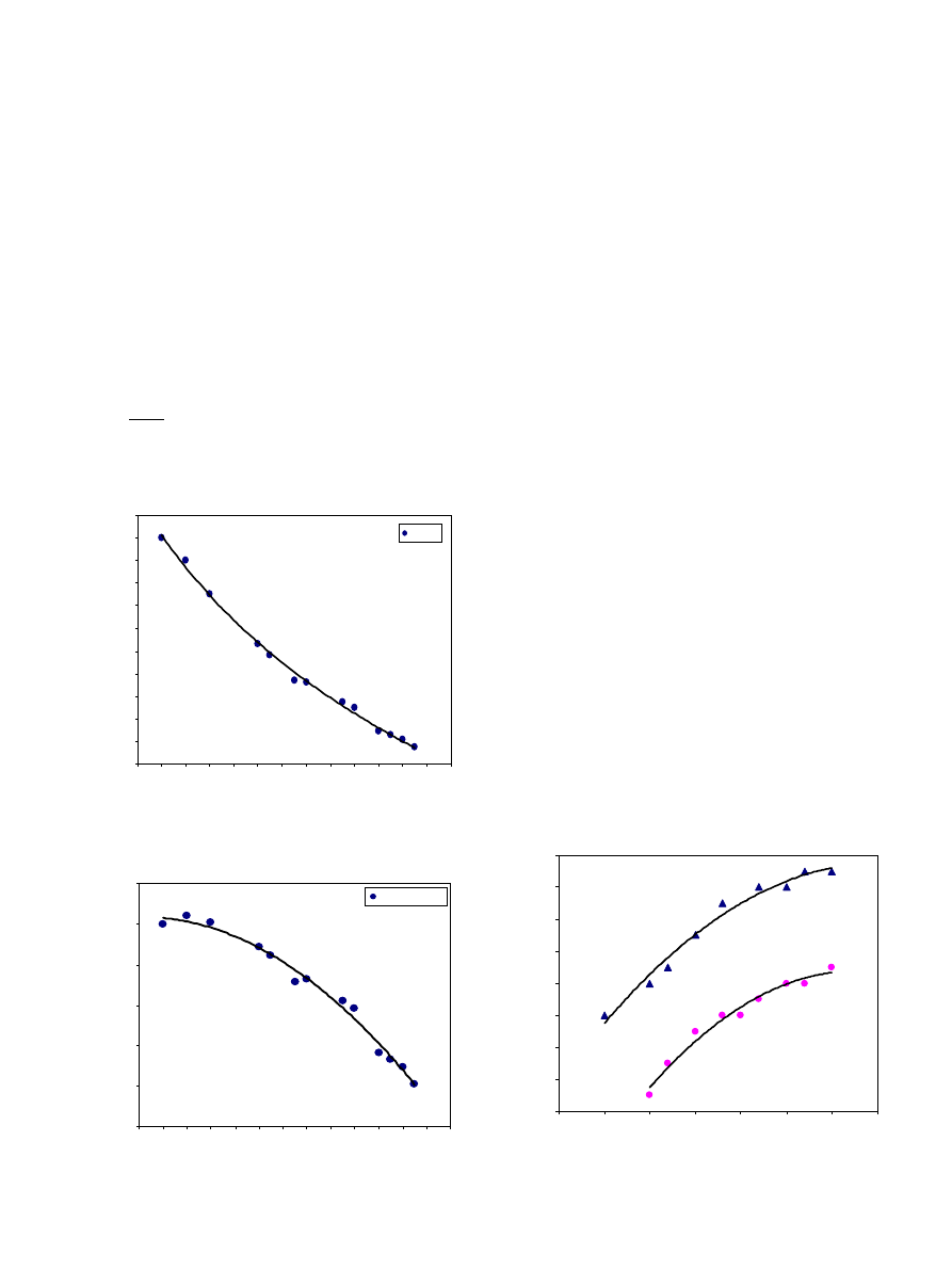
5.2. Engine performance
The engine was constructed and primarily tested at
Shiraz University from 1 to 6 August 2005.
shows
the engine torque variations versus the engine speed. In this
figure, the engine torque T is calculated by multiplying the
brake drum radius r by the downward braking force mg as
shown in
.
T ¼ rmg,
(45)
where m is the mass of the loading weights and g is the
gravitational acceleration.
shows the brake power
versus engine speed. The brake power can be calculated
from dynamics equations as
P
Brake
¼
2pTn
60
,
(46)
where n is engine speed in rpm and T is the engine torque
in Nm.
According to
, the load is gradually applied to the
brake drum, and then the engine speed would be gradually
reduced till a certain applied load would finally shut down
the engine. The experiments were conducted during the
time interval of 11.30–13:00o’clock, when the mean
collector temperature was measured about 110 1C with
minimum fluctuations. The characteristics of torque and
brake power variations represented in
, are
similar to the results of the research published by
Kongtragool and Wongwises
. In these figures, it can
be noted that the torque and the brake power decrease with
an increase in engine speed. This reduction may be
attributed to the lack of rather good heat transfer at
higher engine speed as well as increasing in friction.
5.3. Relationship of collector temperature and engine speed
at no-load condition
The no-load speed of the engine at various collector
temperatures for two different sink temperatures is shown
in
.
It can be illustrated that, the engine speed has been
increased with an increase in the collector temperature. It is
also observed that with decreasing the sink temperature,
the engine speed is effectively increased. These improve-
ments may be due to the high heat transfer potential at
high-temperature gradients.
5.4. The effect of regenerator application on the engine
thermal efficiency
In this research, the engine was designed without
regenerator. An important question would be raised about
the amount of efficiency reduction due to exclusion of the
regenerator. In order to figure out the effect of regenerator
application, a computer program was written to analyze
Eq. (34). The effect of regenerator efficiency variations
ARTICLE IN PRESS
y = -0.186Ln(x) + 0.6646
R
2
= 0.99
0
0.02
0.04
0.06
0.08
0.1
0.12
0.14
0.16
0.18
0.2
0.22
10 12 14 16 18 20 22 24 26 28 30 32 34 36
Engine Speed (rpm)
T
orque (Nm)
Torque
T
C
= 25
°C
T
H
= 110
°C
Fig. 8. Engine torque versus engine speed.
y = -0.0004x
2
+ 0.0083x + 0.2161
R
2
= 0.98
0
0.05
0.1
0.15
0.2
0.25
0.3
10 12 14 16 18 20 22 24 26 28 30 32 34 36
Engine Speed (rpm)
Brake Power (W)
Brake power
T
C
= 25
°C
T
H
= 110
°C
Fig. 9. Brake power versus engine speed.
y = -0.0111x
2
+ 2.8815x - 153.86
R
2
= 0.97
y = -0.0143x
2
+ 3.6365x - 205.22
R
2
= 0.97
18
20
22
24
26
28
30
32
34
95
100
105
110
115
120
125
130
Collector Temperature (degree C)
Engine Speed (rpm)
T
C
= 25
°C
T
C
= 35
°C
Fig. 10. No-load speed of the engine versus collector temperature at
T
C
¼
25 and 35 1C.
A.R. Tavakolpour et al. / Renewable Energy 33 (2008) 77–87
85
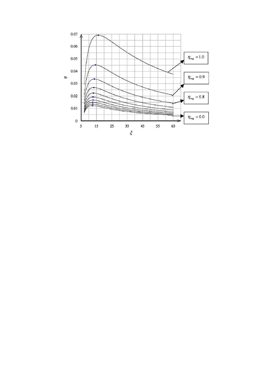
versus the theoretical thermal efficiency of the engine was
investigated. All reference parameters assumed to be
constant according to
except the regenerator
efficiency. The results were shown in
.
It can be argued that the engine thermal efficiency was
effectively improved for the regenerator efficiency of 1.0.
Moreover, the engine thermal efficiency showed a dimin-
ishing trend towards the regenerator efficiency of zero. It
was also observed that the optimized compression ratio
shifted to right due to an increase in the efficiency of
regenerators.
6. Conclusions
In this research, the possibility of generating power
from low temperature sources such as flat-plate solar
collectors was investigated. A very simple two-cylinder
LTD solar Stirling engine without regenerator was
designed and primarily tested. Although the regenerator
was omitted to determine the minimum possible output
power and to simplify the engine structure, but results were
incredible.
The mean engine speed was measured to be 30 rpm at
collector temperature about 107–113 1C and sink tempera-
ture of 25 1C which are approximately similar to the
desirable reference parameters in
. The procedure of
finite dimension thermodynamics is suggested to predict
the engine speed and the internal temperature of expansion
and compression spaces. Therefore, the internal tempera-
ture ratio can be calculated and used in Schmidt theory to
compute a more reliable indicated power. The indicated
power was calculated to be 1.2 W at 30 rpm and the brake
power was measured to be about 0.1 W at 30 rpm.
The application of an efficient regenerator is emphasized
to increase the thermal efficiency. According to
, for
the regenerator efficiency of 1.0 at ideal conditions the
engine thermal efficiency is 0.069 whereas for the regen-
erator efficiency of zero, the engine thermal efficiency is
about 0.0122. Therefore, by using an efficient regenerator,
it is possible to increase the thermal efficiency six times
more.
Upon optimization, the optimal compression ratio was
computed to be 12.5 with collector temperature of about
100 1C, sink temperature of 20 1C and without any
regeneration process. If an efficient regenerator was
employed, the optimal compression ratio would be
increased to 16 according to
.
The corresponding theoretical efficiency of the engine for
the mentioned designed parameters was calculated to be
0.012 for zero regenerator efficiency.
Although the classical Schmidt theory is considered as
one of the most widely used method in designing the
Stirling engines, but its predictions seem to have limit-
ations due to some unreal assumptions of this theory such
as finite heat transfer between the working gas and the
heat exchanger plates. In this study, an effort was
conducted to improve this drawback in Schmidt theory
by calculating the more accurate gas temperature inside
the exchangers. This was done by employing appropriate
heat transfer equations together with the proposed
thermodynamics method to calculate more realistic work-
ing gas temperatures. This finding results in a better
estimation of indicated power of the LTD solar Stirling
engine.
Acknowledgment
The authors wish to express their deep gratitude to Prof.
James Senft from University of Wisconsin-River Falls for
cooperating in this study.
ARTICLE IN PRESS
Fig. 11. Engine thermal efficiency versus compression ratio for different regenerator efficiencies.
A.R. Tavakolpour et al. / Renewable Energy 33 (2008) 77–87
86

References
[1] Walker G. Stirling engines. Oxford: Clarendon Press; 1980. p. 24, 25,
50, 52, 73.
[2] Kongtragool B, Wongwises S. Thermodynamic analysis of a Stirling
engine including dead volumes of hot space, cold space and
regenerator. Renew Energy 2006. p. 346.
[3] Kongtragool B, Wongwises S. A review of solar powered Stirling
engine and low-temperature differential stirling engines. Renew
Sustain Energy Rev 2003;7:131–54.
[4] Senft JR. Ringbom stirling engine. New York: Oxford University
Press; 1993.
[5] Van Arsdell BH. Stirling engines. In: Zumerchik J, editor. Macmillan
encyclopedia of energy. vol. 3. p. 1090–5.
[6] Senft JR. An ultra low-temperature differential Stirling engine. In:
Proceeding of the fifth international Stirling engine conference, paper
ISEC 91032, dubrovnik, May 1991.
[7] Iwamoto
I,
Toda
F,
Hirata
K.
Takeuchi
M,
Yamamoto
T. Comparison of low- and high-temperature differential Stirling
engines. Proceeding of eighth international Stirling engine conference,
1997. p. 29–38.
[8] Kongtragool B, Wongwises S. Investigation on power output of the
gamma configuration low-temperature differential Stirling engine.
Renew Energy 2005;30:465–76.
[9] Kongtragool B, Wongwises S. Optimum absorber temperature of a
once reflecting full conical concentrator of a low-temperature
differential Striling engine. Renew Energy 2005. p. 1671–87.
[10] Kongtragool B, Wongwises S. Performance of low-temperature
differential Stirling engines. Renew Energy 2006. p. 3, 4, 15.
[11] Rochelle P. LTD Stirling engine simulation and optimization
using finite dimension thermodynamic. In: Proceedings of the
12th international Stirling engine conference, Durham University,
2005.
[12] Organ AJ. The regenerator and the stirling engine. London: MEP;
1997.
[13] Meriam
JL,
Karige
LG.
Engineering
mechanics
dynamics.
New York: Wiley; 1997.
ARTICLE IN PRESS
A.R. Tavakolpour et al. / Renewable Energy 33 (2008) 77–87
87
Document Outline
- Simulation, construction and testing of a two-cylinder solar Stirling engine powered by a flat-plate solar collector without regenerator
Wyszukiwarka
Podobne podstrony:
Darrieus Wind Turbine Design, Construction And Testing
British Patent 19,426 Improvements in the Construction and Mode of Operating Alternating Current Mot
Energy performance and efficiency of two sugar crops for the biofuel
Two low temperature Stirling engines, WSZYSTKO O ENERGII I ENERGETYCE, SILNIK STIRLINGA, WIADMOŚCI
HANDOUT do Constr of tests and konds of testing items
Induction of two cytochrome P450 genes, Cyp6a2 and Cyp6a8 of Drosophila melanogaster by caffeine
Comparative testing and evaluation of hard surface disinfectants
A Tale of Two Cities Summary and Themes of the Book
William Pelfrey Billy, Alfred, and General Motors, The Story of Two Unique Men, a Legendary Company
Reviews and Practice of College Students Regarding Access to Scientific Knowledge A Case Study in Tw
The Story Of Two Friends And The Bear
A Woman And a Man Are Two Different Ways of Being a Human
Use of exponential, Page’s and diffusional models to simulate the drying kinetics of kiwi fruit
Comparative testing and evaluation of hard surface disinfectants
Testing and Fielding of the Panther Tank and Lessons for Force XXI
Baerg, W J & W B Peck 1969 A note on the longevity and molt cycle of two tropical theraphosids Bull
05 DFC 4 1 Sequence and Interation of Key QMS Processes Rev 3 1 03
więcej podobnych podstron