
Experimental investigation on micromilling of
oxygen-free, high-conductivity copper using
tungsten carbide, chemistry vapour deposition,
and single-crystal diamond micro tools
D Huo
1
* and K Cheng
2
1
Product Design and Engineering Department, Middlesex University, London, UK
2
Advanced Manufacturing and Enterprise Engineering Department, Brunel University, Uxbridge, UK
The manuscript was received on 17 September 2009 and was accepted after revision for publication on 9 October 2009.
DOI: 10.1243/09544054JEM1828SC
Abstract: Insufficient experimental data from various micro tools limit industrial application
of the micromilling process. This paper presents an experimental comparative investigation
into micromilling of oxygen-free, high-conductivity copper using tungsten carbide (WC),
chemistry vapour deposition (CVD) diamond, and single-crystal diamond micromilling tools at
a uniform 0.4 mm diameter. The experiments were carried out on an ultra-precision micro-
milling machine that features high dynamic accurate performance, so that the dynamic effect
of the machine tool itself on the cutting process can be reduced to a minimum. Micromachined
surface roughness and burr height were characterized using white light interferometry, a
scanning electron microscope (SEM), and a precision surface profiler. The influence of varia-
tion of cutting parameters, including cutting speeds, feedrate, and axial depth of cut, on surface
roughness and burr formation were analysed. The experimental results show that there exists
an optimum feedrate at which best surface roughness can be achieved. Optical quality surface
roughness can be achieved with CVD and natural diamond tools by carefully selecting
machining conditions, and surface roughness, R
a
, of the order of 10 nm can also be obtained
when using micromilling using WC tools on the precision micromilling machine.
Keywords: micromilling, micromachining, OFHC copper, single-crystal diamond tools,
tungsten carbide, CVD diamond, micromachinability
1 INTRODUCTION
High-accuracy miniature components with dimen-
sions ranging from a few hundred micrometres to a
few millimetres, or features ranging from a few to a
few hundred micrometres, are increasingly in demand
for industries such as electro-optics, automotive, bio-
technology, aerospace, medical, and information
and communications technology [1–3]. Some minia-
ture or microcomponents require complex, three-
dimensional (3D) geometries and need to be made
from a variety of engineering materials. The materials
are application-dependent, optical components made
from glass, polymer, or aluminium, medical compo-
nents from polymer or glass, mechanical compo-
nents from ferrous or non-ferrous metals, and dies/
moulds from copper alloys, aluminium, or high-
hardness steels [4–12]. In some particular applica-
tions, microcomponents and microstructures even
require submicrometre accuracy and nanometre sur-
face roughness [13]. It has long been recognized that
traditional MEMS manufacturing techniques, such as
chemical etching and LIGA, are not suitable for pro-
ducing true three-dimensional (3D) micro compo-
nents [8, 14]. Mechanical micromachining is, however,
an ideal method to produce high-accuracy micro-
components in various engineering materials. Among
several mechanical machining processes, micro-
milling is the most flexible and productive process and
*Corresponding author: Product Design and Engineering
Department, School of Engineering and Information Sciences,
Middlesex University, Bramley Road, London N14 4YZ, UK.
email: d.huo@mdx.ac.uk
JEM1828SC
Proc. IMechE Vol. 224 Part B: J. Engineering Manufacture
SHORT COMMUNICATION
995

thus is able to generate a wider variety of complex
microcomponents and microstructures at small and
medium lot size in particular. Some examples of high-
accuracy,
micromilled
components
and
micro-
structures [4–7] are illustrated in Fig. 1.
There are numerous cutting-tool materials being
used in conventional machining processes, and the
properties of these materials vary in terms of hard-
ness, toughness, wear resistance, etc. However, only a
few tool materials have been used for fabricating
micromilling tools. Tungsten carbide (WC) is a pop-
ular tool material widely used in micromachining
processes. There are some micromilling experimental
data on using WC tools available in the literature
[15–17], but data recommended by tool manu-
facturers cannot normally be applied to micromilling
directly. In addition, some micromilling models
based on WC tools have been proposed in the past
five years [16–19].
Coated micro tools, i.e. chemistry vapour deposi-
tion (CVD) diamond or CBN coatings, are used in
some applications to elongate tool life [20]. However,
the thickness of the coatings would significantly
increase the cutting edge radius by a few micro-
metres [21] and thus blunt the tool, although this
might not be an issue for macro-scale cutting tools.
In micromachining, however, the depth of cut is in
the range of a few micrometres, and typical features
of the microcomponent are in the range of tens to
hundreds of micrometres; the well-known size effects
will thus play a significant role and change the whole
machining process physics. Therefore, increasing
the cutting edge radius owing to coatings will nega-
tively affect the micromachining performance [21],
although they have a positive effect in terms of wear
resistance and low cutting friction. More experi-
mental results are expected to assess the coated
microtool performance.
Single-crystal diamond and CVD diamond micro-
milling tools have been introduced to micromachin-
ing in recent years. Single-crystal diamond or CVD
diamond micromilling tools have the potential of
achieving high-dimensional/form accuracy and an
optical surface roughness in various engineering
materials, because they not only offer exceptional
hardness but also have a submicrometre-level cutting
edge radius (typically 1–5
mm for WC and coated
microtools). Up to now, almost no micromilling data
related to single-crystal diamond and CVD diamond
microtools have been reported. Insufficient micro-
milling experimental data are limiting industrial
application of micromilling and the understanding of
surface and burr formation under various cutting
conditions.
Most of the micromilling experiments reported in
the literature were performed in miniature machine
tools (MMTs) [22–26] or conventional machining
centres with retrofitted high-speed spindles [11, 15,
21], which have limited stiffness or accuracy, and
results may not be industrially applicable. Therefore,
optimum cutting conditions from various micro-
milling tools, obtained directly from industrial-
precision micromilling machines rather than MMTs
and test beds, are desirable for micromachining, so as
to bridge the gap.
In this paper, an experimental comparative inves-
tigation into micromilling of oxygen-free, high-
conductivity (OFHC) copper using WC, CVD dia-
mond, and single-crystal diamond milling tools is
presented. The experiments were performed on an
ultra-precision micromilling machine to minimize
the effect of the machine tool itself on the micro-
machining performance. The influence of variation
of cutting parameters, including cutting speeds,
feedrate, and depth of cut, on surface roughness and
burr formation was analysed.
2 EXPERIMENTAL SET-UP AND PROCEDURES
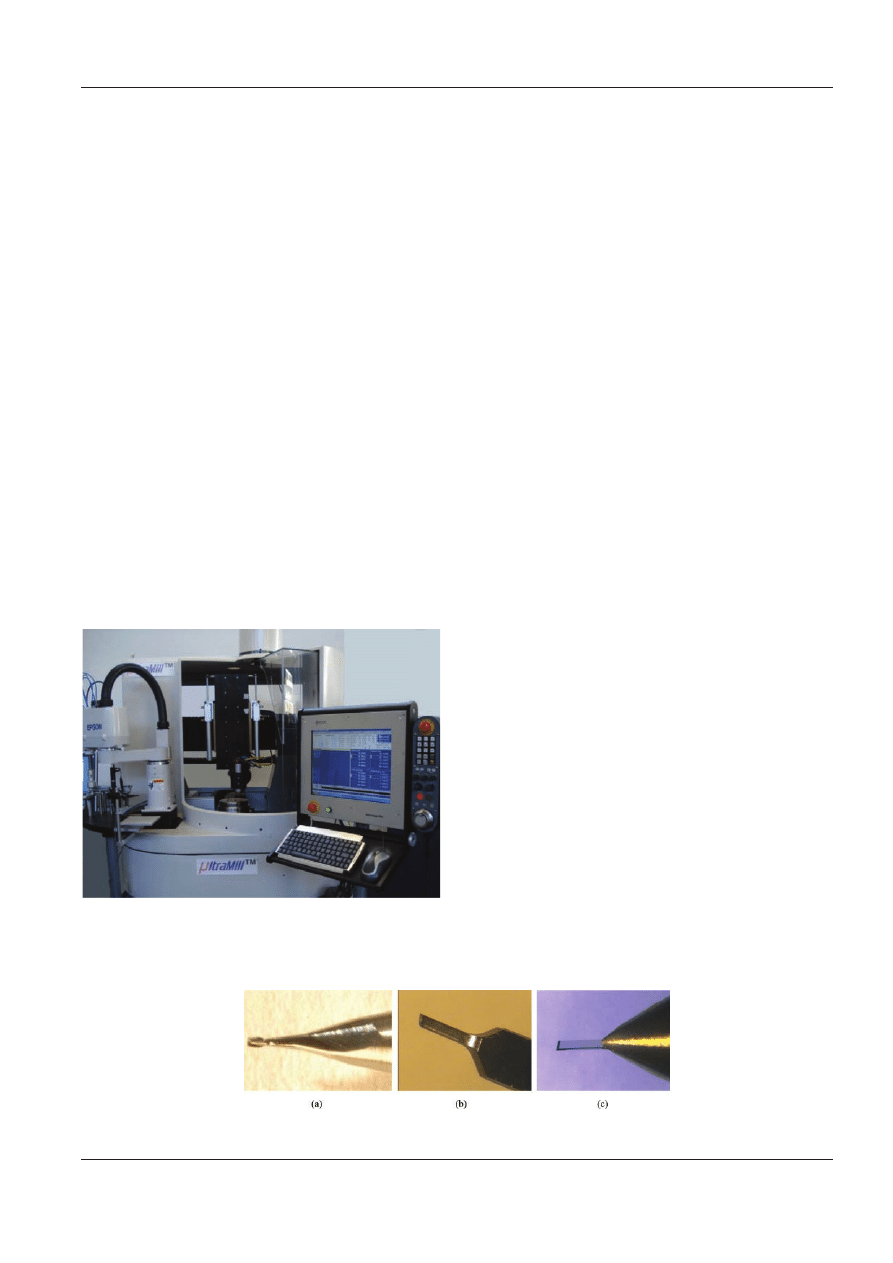
2.1 Ultra-precision micromilling machine:
UltraMill
Experiments for this work were carried out on a five-
axis ultra-precision bench-top micromachine, Ultra-
Mill, which was developed by the authors at Brunel
University (see Fig. 2). The UltraMill is a general-
purpose, ultra-precision micromachine with three
linear axes and two rotary axes. The five-axis config-
uration offers maximum flexibility in tool–workpiece
orientation and minimum need for re-set-up, which
Fig. 1 Examples of high-accuracy micromilled compo-
nents and microstructures: (a) micro trenches [4];
(b) micro mould [5]; (c) micro needles array [6];
(d) micro wall [7]
Proc. IMechE Vol. 224 Part B: J. Engineering Manufacture
JEM1828SC
996
D Huo and K Cheng
is important to achieve high accuracy on micro
parts. Although it is designed for micromachining
micro parts, a relatively large machining envelope of
150
· 150 · 80 mm
3
was specified to enable it to
machine large-size components with micro features.
The overall footprint is about 1 m
2
including the
periphery, which is only 10–20 per cent of that
required by conventional ultra-precision machines.
Aerostatic bearings are employed in the machine
tool throughout, which differs from most of the ultra-
precision machine tools on the market. Three linear
slides are driven by ironless, brushless linear motors,
and the rotary table is driven by a direct-drive torque
motor. In order to improve dynamic stiffness of the
aerostatic bearing, a novel squeezed oil film damper
is fitted to all slides, and the rotary table in the
machine tool developed. Therefore, sub micrometre
machining accuracy under dynamic cutting force
conditions is guaranteed by the above technologies.
The extremely smooth and accurate motion provided
by aerostatic bearings, along with diamond tooling,
also makes nanometre-range surface roughness on
microcomponents possible.
The machine is equipped with a high-speed air
bearing spindle that is driven by a DC brushless
motor. The spindle developed is 63 mm in diameter
and 115 mm in length and weighs 2.5 kg, with a 3 mm
precision four-jawed collet. It has a maximum speed
in excess of 200 000 r/min, a radial runout of less than
2
mm, and a radial stiffness of 3 N/m measured at the
collet end. Bearing friction losses are less than 50 W
at maximum speed, but even so, water cooling is
used to minimize thermal distortion [2].
2.2 Micromilling tools
The micromilling tools used in the experiments
include two-fluted WC end-mills, one-fluted CVD
diamond microtools, and one-fluted single-crystal
diamond microtools. CVD diamond micromilling
tools were fabricated using laser machining, and
single-crystal diamond milling tools were fabricated
using mechanical grinding and polishing. CVD dia-
mond tools can achieve similar machining quality to
that of single-crystal diamond tooling in terms of
accuracy and surface finish, and also have the
advantage of machining ferrous materials that can-
not be processed by single-crystal diamond tooling.
Unfortunately, there are almost no CVD and single-
crystal diamond micromilling data available in the
literature. All micromilling tools have a nominal dia-
meter of 0.4 mm and are capable of full immersion
slot milling. A uniform tool shank diameter of 3 mm
is used for all micro tools to fit the 3 mm precision
spindle collet. Figure 3 shows the three types of
micromilling tool used for the experiments.
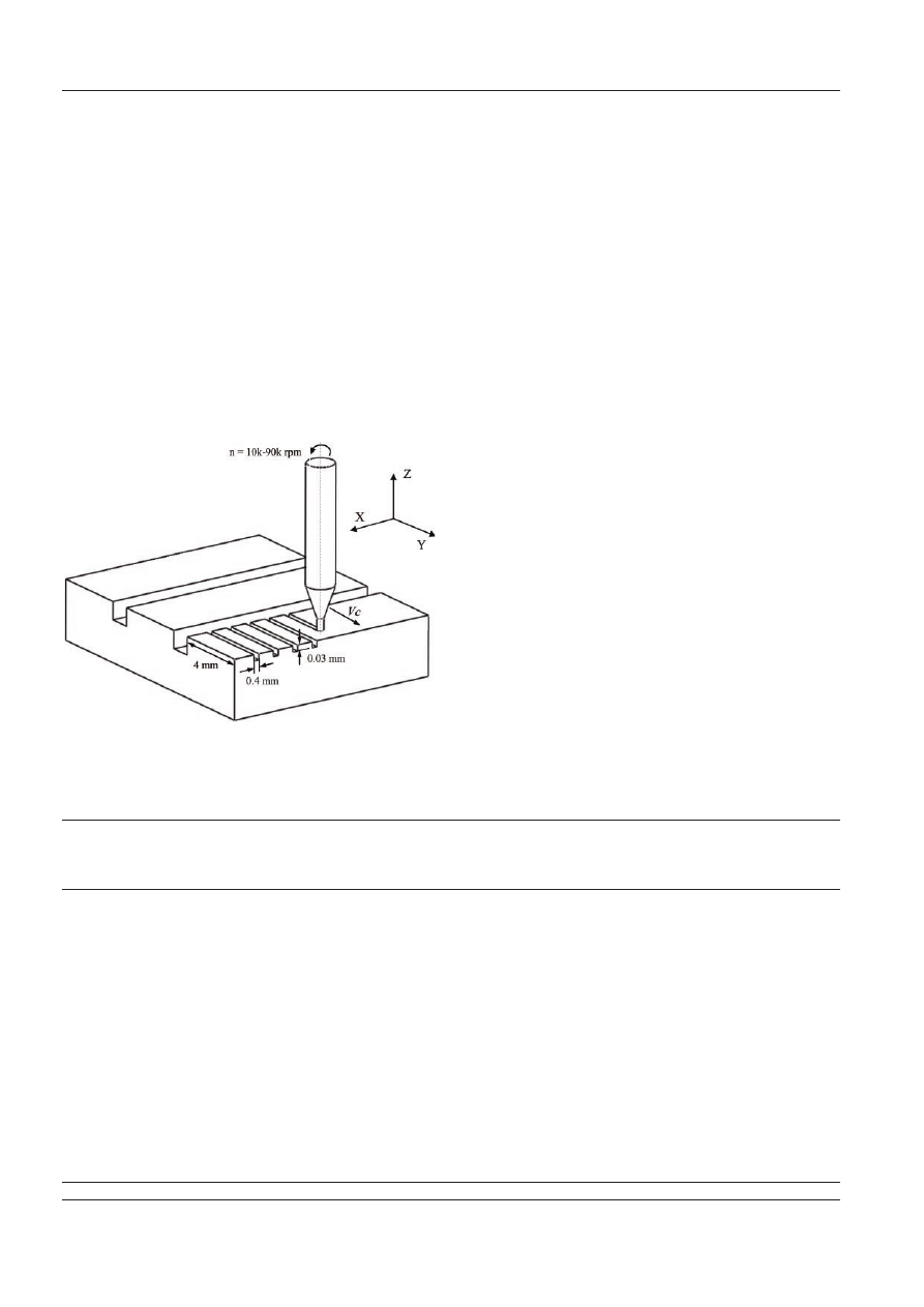
2.3 Procedure and cutting conditions
The experiments in this work include full immersion
slot milling, as illustrated in Fig. 4. For each test, a
micro slot 4 mm long and 0.4 mm wide was milled
along the y-direction. OFHC copper was chosen as
the workpiece material in this work because it has
excellent machinability for both WC and diamond
tools, and it is widely used in the optics and mould
industries. Before experiments, the top surface of the
workpiece was prepared using a 2 mm end-mill. A
small axial depth of cut of 5
mm at each pass was used
for the surface preparation to eliminate surface
damage. A machine vision system (InfiniStix
microscope) is integrated into the machine tool,
providing 3
mm resolution in the z-direction to assist
in positioning the cutter to the workpiece surface.
Fig. 2 The UltraMill – ultra-precision micromilling mach-
ine: (a) WC; (b) CVD diamond; (c) single-crystal
diamond
Fig. 3 Micromilling tools used in the experiments (courtesy of Contour Fine Tooling Limited)
JEM1828SC
Proc. IMechE Vol. 224 Part B: J. Engineering Manufacture
Experimental investigation on micromilling
997
The feed per tooth F
z
was varied at 0.1
mm, 0.2 mm,
0.5
mm, 1 mm, 2 mm, 3 mm, and 4mm, respectively, at a
constant axial depth of cut of 30
mm. The wide range
of feedrate was chosen to ensure that minimum chip
thickness for all three cutters and workpiece combi-
nations falls into this range, so that the size effect due
to the minimum chip thickness can be investigated.
The spindle speed n was varied at 10 000, 30 000,
60 000, and 90 000 r/min, respectively, during these
experiments. Effect of axial depth of cut d was also
studied by varying its value from 10
mm to 100 mm at
intervals of 10
mm, and fixing the spindle speed at
60 000 r/min. Oil-based coolant mist was sprayed
onto the cutting zone during all of the micromilling
experiments. The aforementioned experiments were
repeated on all three types of micro tool. The full ex-
perimental matrix is listed in Table 1.
In order to reduce the influence of tool wear on the
surface and burr formation, brand new micro tools
were used for each set of experiments. An extra slot
(experiment 39) was milled at the end of the experi-
ments using the same cutting conditions as for the
first slot (see Table 1). This validation slot was then
compared with the first slot (experiment 1). For the
three types of micro tool, it is observed that there is
no significant difference between experiments 1 and
39 in terms of surface roughness, slot width, and burr
height. Therefore, the tool wear effect is regarded as
negligible for the cutting distance used in this work.
2.4 Surface roughness and burr height
measurement
The surface roughness of the bottom surface of the
micromilled slots was measured using a white light
interferometer (Zygo NewView 5000) along the cen-
treline of the slots. To reduce the measurement
uncertainty and assess repeatability, five measure-
ments on different areas were conducted for each
slot, and an average value of surface roughness (R
a
)
was used for analysis. There is no standard method of
evaluating burr formation. In this research, an aver-
age burr height measured across the slot was used
quantitatively to assess burr formation. Five mea-
surements of burr height were recorded using a sur-
face profiler (Talysurf Serial-2), and an average value
was calculated for discussion.
Table 1
Experimental matrix for micromilling using WC, CVD, and single-crystal diamond milling tools
Experiment
no.
Depth
of cut, d
(mm)
Spindle
speed, n
(r/min)
Cutting
speed,
V
c
(m/min)
Feedrate,
F
z
(
mm/flute)
Experiment
no.
Depth
of cut,
d
(mm)
Spindle
speed, n
(r/min)
Cutting
speed,
V
c
(m/
min)
Feedrate,
F
z
(
mm/flute)
1
0.03
10 000
12.56
0.1
21
0.03
60 000
75.36
4
2
0.03
10 000
12.56
0.2
22
0.03
90 000
113.04
0.1
3
0.03
10 000
12.56
0.5
23
0.03
90 000
113.04
0.2
4
0.03
10 000
12.56
1
24
0.03
90 000
113.04
0.5
5
0.03
10 000
12.56
2
25
0.03
90 000
113.04
1
6
0.03
10 000
12.56
3
26
0.03
90 000
113.04
2
7
0.03
10 000
12.56
4
27
0.03
90 000
113.04
3
8
0.03
30 000
37.68
0.1
28
0.03
90 000
113.04
4
9
0.03
30 000
37.68
0.2
29
0.01
60 000
75.36
0.5
10
0.03
30 000
37.68
0.5
30
0.02
60 000
75.36
0.5
11
0.03
30 000
37.68
1
31
0.03
60 000
75.36
0.5
12
0.03
30 000
37.68
2
32
0.04
60 000
75.36
0.5
13
0.03
30 000
37.68
3
33
0.05
60 000
75.36
0.5
14
0.03
30 000
37.68
4
34
0.06
60 000
75.36
0.5
15
0.03
60 000
75.36
0.1
35
0.07
60 000
75.36
0.5
16
0.03
60 000
75.36
0.2
36
0.08
60 000
75.36
0.5
17
0.03
60 000
75.36
0.5
37
0.09
60 000
75.36
0.5
18
0.03
60 000
75.36
1
38
0.1
60 000
75.36
0.5
19
0.03
60 000
75.36
2
39
0.03
10 000
12.56
0.1
20
0.03
60 000
75.36
3
Fig. 4 Schematic diagram of the micromilling experiment
Proc. IMechE Vol. 224 Part B: J. Engineering Manufacture
JEM1828SC
998
D Huo and K Cheng
3 RESULTS AND DISCUSSIONS
This section presents the experimental results and
the associated discussions. First, surface roughness
results obtained from the three types of micro tool are
discussed, followed by the burr formation discussion.
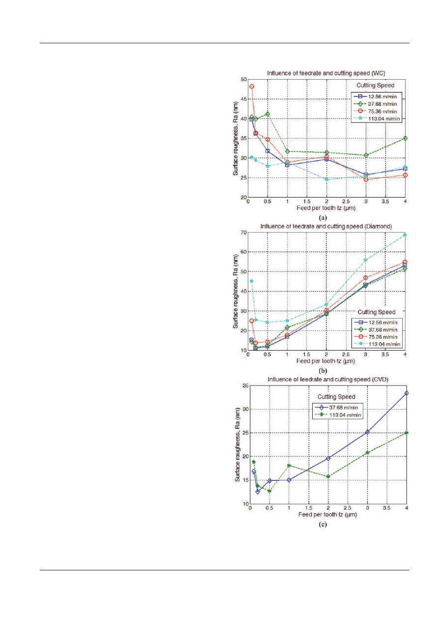
3.1 Surface roughness
Figure 5 shows average surface roughness R
a
as a
function of feedrate at various cutting speeds for the
three types of micromilling tool. It can be observed
from Figs 5(b) and (c) that, for CVD and single-crystal
diamond micro tools, the tendency is towards higher
roughness values with increases in feedrate when the
feedrate is greater than 0.5
mm/tooth. However, when
the feedrate is smaller than 0.5
mm/tooth, the rough-
ness value decreases with increases in feedrate. The
smallest surface roughness for single-crystal diamond
tools is observed around 11 nm, occurring at 0.2
mm/
tooth, and a cutting speed of 12.56 m/min; the smal-
lest surface roughness for CVD diamond tools is
observed around 13 nm, occurring at 0.2
mm/tooth,
and a cutting speed of 37.68 m/min. The good surface
roughness obtained from micromilling using CVD
and single-crystal diamond tools indicates that an
optical surface roughness can be achieved in micro-
milling by carefully selecting cutting conditions.
The tendency of surface roughness results for WC
tools is towards a lower roughness value with an
increase in feedrate, until the feedrate exceeds 3
mm/
tooth (see Fig. 5(a)), which is different from that of
CVD and single-crystal diamond tools. Under the
cutting conditions in this work, a surface roughness,
R
a
, between 24 and 50 nm was achieved. The smallest
R
a
value of 24 nm was observed at a feedrate of 3
mm/
tooth and a cutting speed of 75.36 m/min. It should
be noted that the surface roughness results and the
smallest R
a
value of 24 nm achieved in this work are
much better than some micromilling data obtained
from miniature micromachine tools in the literature.
This indicates that the micromilled surface rough-
ness depends, not only on the cutting tools and cut-
ting conditions, but also on the whole machining
system, including the motion errors of slideways and
spindle runout, etc.
Generally, for all three types of micro tool, spindle
speed has no significant effect on the surface rough-
ness. However, for CVD and single-diamond tools,
cutting speeds have a negative effect on the surface,
i.e. the higher the cutting speed, the higher the sur-
face roughness value, especially for higher cutting
speeds (see Figs 5(b) and (c)). By contrast, this trend
has not been found in WC micromilling experiments.
When the feed per tooth (i.e. depth of cut) is of the
same order as the tool edge radius, the effective rake
angle may become negative. Size effects resulting
Fig. 5 Average surface roughness R
a
as a function of feed-
rate and cutting speed: (a) WC tool; (b) single-
crystal diamond tool; (c) CVD diamond tool
JEM1828SC
Proc. IMechE Vol. 224 Part B: J. Engineering Manufacture
Experimental investigation on micromilling
999
from a small ratio of chip thickness to tool edge
radius will be a dominant factor for the material
removal mechanism and chip generation physics in
micromachining. Cutting, ploughing, or slipping
phenomena will occur, predominated by this ratio,
and will eventually influence machining processes
such as surface roughness and burr formation. In
previous ultra-precision machining studies, numer-
ous researchers have investigated this size effect, and
the critical minimum chip thickness was reported to
be around 10–40 per cent of cutting edge radius [5,
27–30]. WC micro tools used in this work have a
cutting edge radius in the range of 3–6
mm measured
by a scanning election microscope (SEM) for the
same batch of micro tools, whereas CVD diamond
and single-crystal diamond micro tools have a cut-
ting edge radius of 0.2
mm as quoted by the manu-
facturer. The minimum chip thickness can well be
used to explain that there exists an optimum feedrate
at which micromilling produces the best surface
roughness, as discussed above.
Compared with two-fluted WC micro tools, CVD
and single-crystal diamond tools with one sharp cut-
ting edge are prone to instability, because there is
always either only one single cutting edge in contact
with the workpiece or no contact with the workpiece,
which causes periodic variation of the cutting force
and poor surface roughness. For diamond micro-
milling, surface roughness increases sharply with
feedrate when the feedrate exceeds 0.5
mm/tooth (see
Fig. 5(b)), indicating that good surface roughness can
only be achieved in diamond micromilling over a
limited feedrate range (0.2–1.0
mm/tooth). By contrast,
good surface roughness was achieved from a wider
feedrate range in the WC micro tools experiments.
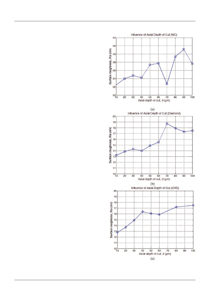
Figure 6 shows average surface roughness R
a
as a
function of axial depth of cut. Compared with the
effect of feedrate on the surface roughness, there
were no substantial differences for all three types of
micromilling tool – surface roughness R
a
increased
slightly with axial depth of cut. Under the same feed-
rate and cutting speed, the R
a
value for the deepest
cut (100
mm) was just slightly higher than that for the
shallowest cut (10
mm). Therefore, using a larger axial
depth of cut is an effective way of increasing the
machining efficiency, assuming that tool breakage
and wear are not issues.
3.2 Burr formation
Burrs in micromachining can be categorized in a
number of ways. According to their position, burrs can
be classified as entrance, exit, top, and bottom burrs.
Burrs in micromachining can be classified into four
types of burr according to their shape and amount:
primary burr, needle-like burr, feathery burr, and
minor burr [31]. Sizes of entrance and exit burrs were
Fig. 6 Average surface roughness R
a
as a function of axial
depth of cut: (a) WC tool; (b) single-crystal diamond
tool; (c) CVD diamond tool
Proc. IMechE Vol. 224 Part B: J. Engineering Manufacture
JEM1828SC
1000
D Huo and K Cheng
found to be small, and bottom burrs were ignorable in
this work. Top burrs were observed and measured in
this work. Because the top burrs in this work were
uniform minor burrs, average burr heights measured
across the slot were used quantitatively to investigate
the relationship between cutting conditions and burr
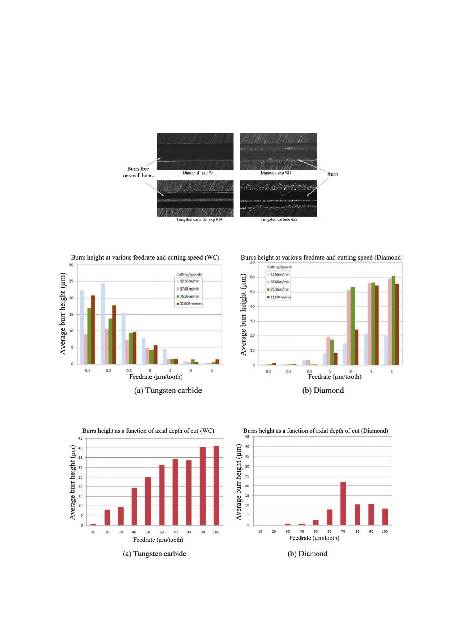
formation. Figure 7 shows some examples of burr
formation using diamond and WC cutters.
Burr height at various feedrates and cutting speeds
is plotted in Fig. 8, and its variation with axial depth
of cut is plotted in Fig. 9. In general, the relationship
between burr height and cutting conditions was
Fig. 8 Burr height at various feedrates and cutting speeds: (a) WC; (b) diamond
Fig. 7 Examples of burr formation for diamond and WC cutters
Fig. 9 Burr height as a function of axial depth of cut: (a) WC; (b) diamond
JEM1828SC
Proc. IMechE Vol. 224 Part B: J. Engineering Manufacture
Experimental investigation on micromilling
1001

observed to be similar to that between surface
roughness and cutting conditions. When the axial
depth of cut is 30
mm, burr-free or small-burr-height
(
< 5 mm) cutting was found at a feedrate range of less
than 0.5
mm/tooth for diamond tools and a feedrate
range of 1–4
mm/tooth for WC micro tools, respec-
tively (see Fig. 8). Good surface roughness normally
corresponds to small top burr height for both dia-
mond and WC micro tools, which makes cutting
parameter optimization less complex. With an
increase in the axial depth of cut, for the diamond
and WC tools, the burr height tends to increase (see
Fig. 9). Cutting speed was found to have no sig-
nificant effect on burr height. However, for WC tools
a medium cutting speed (37.68 m/min) produces
fewest burrs, and for diamond tools a high cutting
speed (113.04 m/min) helps to reduce burr form-
ation, although more experimental data are needed
further to verify this finding.
4 CONCLUSIONS AND FUTURE WORK
This paper presents an experimental investigation of
micromilling OFHC copper on an ultra-precision
micromilling machine. Tungsten carbide, CVD, and
single-crystal diamond micro end-mills with 0.4 mm
diameter were used to create full-width slots. Various
cutting conditions, including feedrate, spindle speed,
and axial depth of cut, were experimentally investi-
gated, particularly in their influence on surface
roughness and burr formation. The following major
conclusions can be drawn from this work.
1. In micromilling using those three types of cutter,
feedrate has a significant influence on surface
roughness and burr height, whereas spindle speed
has a slight influence on the surface roughness
and burr formation. Axial depth of cut has no
significant influence on the surface roughness;
therefore, using a larger axial depth of cut is an
effective way to increase machining efficiency.
2. The existence of the minimum chip thickness
dominates the chip and surface formation at a
certain feedrate range and determines the opti-
mum feedrate and achievable surface roughness.
3. The micromilling experiments demonstrate that,
if 0.4 mm diameter micro tools are used, the
achievable surface roughness R
a
can reach
approximately 10 nm for CVD and single-crystal
diamond micromilling tools and 24 nm for com-
mercial WC micro tools through careful selection
of machining conditions and the use of precision
micromilling machines. The experimental results
in this work provide practical and industrially
feasible micromilling data using CVD and single-
crystal diamond micromilling tools on precision
micromilling machines.
Future efforts will be directed towards using wider
cutting conditions and systematic modelling of the
micromilling process based on more comprehensive
cutting trial data.
ACKNOWLEDGEMENTS
The authors are grateful for the support of the EU
6th Framework NMP Program under contract num-
ber NMP2-CT-2–4-500095. Thanks are due to all
partners of MASMICRO project consortium and to
those within the RTD 5 subgroup in particular for the
stimulating meetings and discussions. Thanks are
also extended to Contour Fine Tooling Limited for
providing the micro end-mills, and Paul Yates, Khalid
Nor, and Tao Wu at Brunel University for their
assistance in the work.
Authors 2010
REFERENCES
1 Ehmann, K. F., Bourell, D., Culpepper, M. L.,
Hodgson, T. J., Kurfess, T. R., Madou, M., Rajurkar, K.,
and DeVor, R. E. International assessment of research
and development in micromanufacturing, World Tech-
nology Evaluation Center, Baltimore, Maryland, 2005.
2 Huo, D., Cheng, K., and Wardle, F. Design of a 5-axis
ultraprecision micromilling machine – UltraMill: part 1:
holistic design approach, design considerations, speci-
fications. Int. J. Advd Mfg Technol., 2009. DOI: 10.1007/
s00170-009-2128-2.
3 Huo, D., Cheng, K., and Wardle, F. Design of a 5-axis
ultraprecision micromilling machine – UltraMill: part 2:
integrated dynamic modelling, design optimization and
analysis. Int. J. Advd Mfg Technol., 2009. DOI: 10.1007/
s00170-009-2129-1.
4 Friedrich, C. R. and Vasile, M. J. Development of
micromilling process for high-aspect-ratio microstruc-
ture. J. Microelectromechanical Syst., 1996, 5, 33–38.
5 Weule, H., H
€untrup, V., and Tritschler, H. Micro-
cutting of steel to meet new requirements in miniatur-
ization. Ann. CIRP, 2001, 50(1), 61–64.
6 Takeuchi, Y., Suzukawa, H., Kawai, T., and Sakaida, Y.
Creation of ultraprecision microstructures with high
aspect ratio. Ann. CIRP, 2006, 56(1), 107–110.
7 Weck, M., Hennig, J., and Hilbing, R. Precision cutting
processes for manufacturing of optical components.
Proc. SPIE, 2001, 4440, 145–151.
8 Liu, X., DeVor, R. E., Kapoor, S. G., and Ehmann, K. F.
The mechanics of machining at the microscale: Assess-
ment of the current state of the science. Trans. ASME, J.
Mfg Sci. Engng, 2004, 126(4), 666–678.
9 Brinksmeier, E., Riemer, O., and Stern, R. Machining
of precision parts and microstructures. In Proceedings
of the 10th International Conference on Precision engi-
neering (ICPE), initiatives of precision engineering at the
beginning of a millennium, Yokohama, Japan, 18–20
July 2001, S. 3–11.
Proc. IMechE Vol. 224 Part B: J. Engineering Manufacture
JEM1828SC
1002
D Huo and K Cheng

10 Damazo, B. N., Davies, M. A., Dutterer, B. S., and
Kennedy, M. D. A summary of micromilling studies.
In proceedings of the First International Conference
and General Meeting of the European Society of
Precision Engineering and Nanotechnology, Bremen,
Germany, 31 May–4 June 1999, pp. 322–325.
11 Bissacco, G., Hansen, H. N., and Chiffre, L. D. Micro-
milling of harded tool steel for mould making applica-
tions. J. Mater. Proc. Technol., 2005, 167, 201–207.
12 Huo, D. and Cheng, K. A dynamics-driven approach to
precision machines design for micro-manufacturing
and its implementation perspectives. Proc. IMechE,
Part B: J. Engineering Manufacture, 2008, 222(B1), 1–8.
DOI: 10.1243/09544054JEM839.
13 Sweatt, W. C., Gill, D. D., Adams, D. P., Vasile, M. J.,
and Claudet, A. A. Diamond milling of micro-optics.
IEEE A&E Syst. Mag., 2008, Jan, 13–17.
14 Chae, J., Park, S. S., and Freiheit, T. Investigation of
micro-cutting operations. Int. J. Mach. Tools Mf., 2006,
46(3–4), 313–332.
15 Rahman, M., Kumar, A. S., and Prakash, J. R. S.
Micromilling of pure copper. J. Mater. Proc. Technol.,
2001, 116, 39–43.
16 Vogler, M. P., DeVor, R. E., and Kapoor, S. G. On the
modeling and analysis of machining performance in
micro-endmilling, Part I: surface generation. Trans.
ASME, J. Mfg Sci. Engng, 2004, 126, 685–694.
17 Vogler, M. P., DeVor, R. E., and Kapoor, S. G. On
the modeling and analysis of machining performance
in micro-endmilling, Part II: cutting force prediction.
Trans. ASME, J. Mfg Sci. Engng, 2004, 126, 695–705.
18 Kim, C. J., Mayor, J. R., and Ni, J. A static model of chip
formation in microscale milling. Trans. ASME, J. Mfg Sci.
Engng, 2004, 126, 710–718.
19 Lai, X., Li, H., Li, C., Lin, Z., and Ni, J. Modelling and
analysis of micro scale milling considering size effect,
micro cutter edge radius and minimum chip thickness.
Int. J. Mach. Tools Mf., 2008, 48, 1–14.
20 Rusnaldy, X., Ko, T. J., and Kim, H. S. Micro-end-
milling of single-crystal silicon. Int. J. Mach. Tools Mf.,
2007, 47(14), 2111–2119.
21 Torres, C. D., Heaney, P. J., Sumant, A. V.,
Hamilton, M. A., Carpick, R. W., and Pfefferkorn, F. E.
Analyzing the performance of diamond-coated micro
end mills. Int. J. Mach. Tools Mf., 2009, 49(7–8), 599–
612.
22 Kussul, E., Baidyk, T., Ruiz-Huerta, L., Caballero-Ruiz,
A., Velasco, G., and Kasatkina, L. Development of
micromachine tool prototypes for microfactories. J.
Micromech. Microengng, 2002, 12(6), 795–812.
23 Vogler, M. P., Liu, X., Kapoor, S. G., Devor, R. E., and
Ehmann, K. F. Development of meso-scale machine
tool (MMT) systems. Society of Manufacturing Engi-
neers, 2002, Paper MS02–181, 1–9.
24 Bang, Y. B., Lee, K. M., and Oh, S. 5-axis micromilling
machine for machining micro parts. Int. J. Advd Mfg
Technol., 2005, 25, 888–894.
25 Lee, S. W., Mayor, R., and Ni, J. Dynamic analysis of a
mesoscale machine tool. Trans. ASME: J. Mfg Sci. Engng,
2006, 128(1), 194–203.
26 Li, H., Lai, X., Li, C., Lin, Z., Miao, J., and Ni, J. Devel-
opment of meso-scale milling machine tool and its
performance analysis. Frontiers Mech. Engng China,
2008, 3(1), 59–65.
27 Filiz, S., Conley, C. M., Wasserman, M. B., and
Ozdoganlar, O. B. An experimental investigation of
micro-machinability of copper 101 using tungsten car-
bide micro-endmills. Int. J. Mach. Tools Mf, 2007,
47(7–8), 1088–1100.
28 Ikawa, N., Shimada, S., and Tanaka, H. Minimum
thickness of cut in micromachining. Nanotechnology,
1992, 3, 6–9.
29 Ikawa, N., Donaldson, R. R., Komanduri, R., K
€onig, W.,
Aachen, T. H., McKeown, P. A., Moriwaki, T., and
Stowers, I. F. Ultra-precision metal cutting – the past,
the present and the future. Ann. CIRP, 1991, 40(2), 587–
594.
30 Yuan, Z. J., Zhou, M., and Dong, S. Effect of diamond
tool sharpness on minimum cutting thickness and cut-
ting surface integrity in ultra-precision machining.
J. Mater. Proc. Technol., 1996, 62, 327–330.
31 Chern, G. L., Wu, Y. J. E., Cheng, J. C., and Yao, J. C.
Study on burr formation in micro-machining using
micro-tools fabricated by micro-EDM. Precis. Engng,
2007, 31, 122–129.
JEM1828SC
Proc. IMechE Vol. 224 Part B: J. Engineering Manufacture
Experimental investigation on micromilling
1003
Wyszukiwarka
Podobne podstrony:
07 Experimental study on characteristics of high strength blind bolted joints
Experimental study on drying of chilli in a combined Microwave vacuum rotary drum dryer (Weerachai K
Interruption of the blood supply of femoral head an experimental study on the pathogenesis of Legg C
34 453 476 Creep of HSS Part I Experimental Investigations
An experimental study on the development of a b type Stirling engine
95 1373 1389 A new Investigation on Mechanical Properties of Ferro Titanit
Interruption of the blood supply of femoral head an experimental study on the pathogenesis of Legg C
34 453 476 Creep of HSS Part I Experimental Investigations
An experimental study on the drying kinetics of quince
Torsion Experimental Investigation of New Long range Actions Nachalov & Sokolov p11
Experimental investigation of transverse vibration assisted orthogonal cutting of AL 2024
The?onomic Emergence of China, Japan and Vietnam
spicze ways of spending free time
The?onomic Underpinnings of the First British Industrial R
deRegnier Neurophysiologic evaluation on early cognitive development in high risk anfants and toddl
więcej podobnych podstron