
Full-Toroidal Variable Drive Transmission Systems in Mechanical
Hybrid Systems – From Formula 1 to Road Vehicles
Chris Brockbank BSc (Hons) & Chris Greenwood BSc (Hons)
Torotrak (Development) Ltd
1. Introduction
As reported at the 2008 CTI Transmission Symposium in Southfield, Formula 1 is introducing
hybrid drivetrain technologies for the 2009 race season.
In order to promote technical development into all potential hybrid solutions, the specification
of the hybrid system has purposefully been kept open and simple; all that has been specified
is that a defined amount of energy (400kJ) at a defined maximum rate (60kW) can be
recovered and reapplied each lap. The clear intent is to direct motorsport developments to
impact the key issue of fuel efficiency in mainstream on-road vehicles.
The outcome is a fresh investigation into hybrid architectures resulting in technical
developments to achieve highly efficient, lightweight, compact hybrid drivetrain systems
whilst providing the exhilaration a Formula 1 devotee craves via a “Push to Pass” boost
system.
Torotrak is participating in the development of a mechanical Kinetic Energy Recovery
System (KERS) which utilises the full-toroidal traction drive variator connected to a high
speed flywheel. Following the FIA’s (Federation Internationale L’Automobile – Formula 1’s
organising body) purpose of Formula 1 developing technology in racing for application in
mainstream vehicles, the system has been developed from the racing design to a hybrid
system suitable to volume production in mainstream automotive applications.
The paper describes the key elements of the Formula 1 KERS and discusses its extension to
passenger cars and bus applications.

2. Formula 1 Mechanical KERS
The Formula 1 KERS for the 2009 season is allowed to recover, store and reapply 400 kJ of
energy per lap to and from the vehicle at a maximum rate of 60 kW. Although a relatively low
power and energy recovery requirement given the quantity of energy dissipated by a Formula
1 car under braking, when one recognises that the existing ~550 kW engine remains
unchanged, the safety implications of limiting an additional power boost are clear.
In addition, 60 kW is a significant quantity of power for a hybrid system to deliver to a road
vehicle. Depending upon the automotive application, the energy storage quantity may be
maintained at the 400kJ or increased.
The 400 kJ / 60 kW specification will remain for at least the 2010 Formula 1 season with
discussions regarding downsizing the engine and running a higher specification KERS (e.g.
circa 200 kW) ongoing for future seasons.
A Formula 1 car has similar requirements for a hybrid system as a road car – both vehicles
require a rapid recovery of energy from the vehicle inertia, high efficiency in the transfer of
the energy to and from the storage medium, high efficiency of the storage medium itself and
delivered with high energy density in a small package with low weight.
As described at this conference last year, a mechanical storage medium of a flywheel
connected via a variable drive to the vehicle driveline has advantages in weight, package,
cost, performance degradation and overall efficiency to the incumbent battery / electric motor
systems currently applied to road vehicles
To deliver a functional system to the F1 community, a partnership of three companies was
generated comprising Flybrid Systems (an independent, innovative engineering company
comprising Engineers from F1 who are developing mechanical hybrid technology including
the flywheel), Xtrac (a specialist transmission supplier to the motorsport, aerospace and
automotive sectors) and Torotrak as the CVT technology supplier.
The mechanical KERS comprises the Flybrid Systems’ flywheel and the Xtrac sourced,
Torotrak variable drive unit is shown below :-
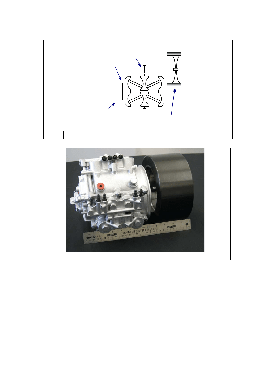
Input
Drive
Clutch
Flywheel
Step-up
Drive
Fig. 1
KERS Configuration
Reproduced courtesy of Flybrid Systems LLC
Fig. 2 F1 KERS – CVT and Flywheel
The Flybrid Systems’ Formula 1 flywheel comprises a carbon fibre filament wound rim
surrounding a steel hub. Weighing in at circa 5kg with a diameter of 200mm and a length of
100mm, the flywheel spins at high speeds with an operating range of 64,500 rpm to 32,250
rpm. Operating in air would result in friction between the flywheel rim and the air causing
both an efficiency losses and heating the carbon rim, potentially above its glass transition
temperature. Therefore, the flywheel therefore runs in a vacuum and is enclosed within a
housing that provides containment in the event of failure.
Total system weight for the flywheel, housing gear drives and CVT is less than 25kg.
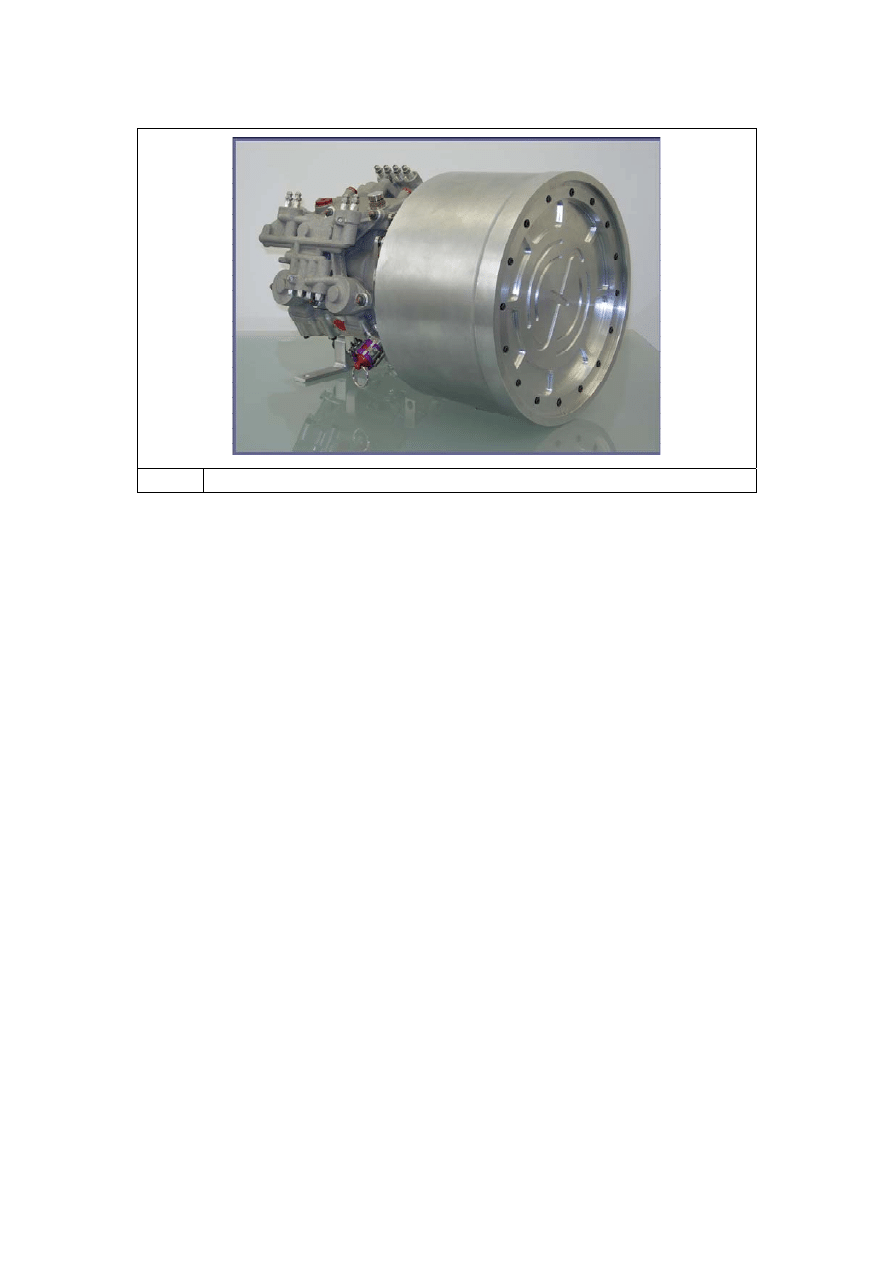
Reproduced courtesy of Flybrid Systems LLC
Fig. 3
: Formula 1 Mechanical KERS
3. KERS
Transmission
System
As the Torotrak variable drive system is torque controlled, the Variator transfers the energy
to and from the flywheel irrespective of the speeds of the driveline of the flywheel. The
familiar twin cavity “compact lever” roller control design of Torotrak’s full-toroidal Variator is
utilised producing a compact variable drive system.
The calculation process for defining the Torotrak Variator specification was described last
year with contact stresses, temperatures and efficiencies compared together with the
package requirements to determine the following specification :-
•
Ratio spread = 6
•
Twin cavity, 3 disc / 6 roller design
•
Roller diameter ~ 55mm
•
Disc diameter ~ 103mm
•
Compactness ratio = 1.18
•
Lever roller control design
•
Disc and roller weight ~2.7 kg
•
CVT weight ~5 kg
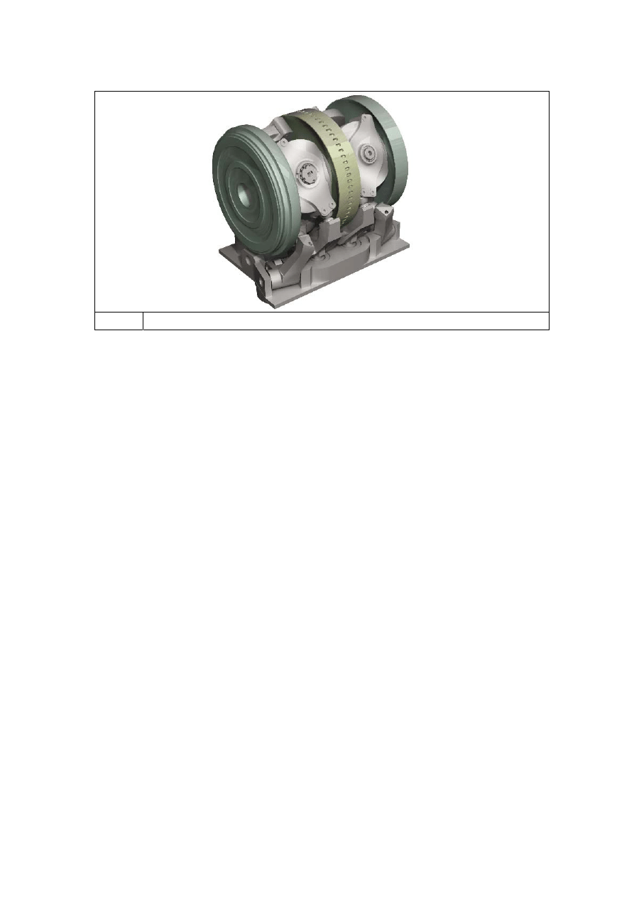
Fig. 4
Compact Lever Variator
4. Road
Car
Applications
Flywheel energy storage systems for passenger vehicles are not a new concept – a number
of systems have previously been developed with examples including a system by the
Technical University of Eindhoven and another by Torotrak with Leyland Trucks which
demonstrated a flywheel kinetic energy storage system in a bus in the 1980’s. It is also
possible to ride on a flywheel powered tram from Stourbridge Junction in England. Flywheel
based systems are not without their areas requiring focus – most notably the containment of
the rotating mass and the method of control and transmission of the energy to and from the
flywheel – which have inhibited development and mainstream application. The FIA initiative
has successfully ‘kick-started’ technical developments in these areas resulting in technical
solutions to the previously viewed issues.
System efficiency is a key area where the mechanical hybrid system excels over the electric
hybrid. Battery based electric hybrid systems require a number of energy conversions each
with corresponding efficiency losses (e.g. mechanical to electrical energy, AC to DC, DC
electrical energy to chemical energy in a battery). On reapplication of the energy to the
driveline, the energy conversions are repeated. The result is a circa 31% to 34% round trip
efficiency.
The mechanical hybrid system stores the recovered energy mechanically in a rotating
flywheel hence eliminating the various energy conversions and providing a far more efficient

system. Measured round trip efficiencies for the mechanical system exceed 70% – twice as
efficient as an electric system.
The first stage in developing a mechanical hybrid specification for mainstream automotive
applications is to predict the potential fuel consumption reduction for a target application. A
number of criteria (including the quantity of energy storage, the power transfer rate, ratio
range of the system, etc) can then be optimised to determine the maximum benefit to the
vehicle.
To simulate the benefit of the mechanical hybrid powertrain, a generic 2000 kg D / E class
base vehicle specification was created comprising a ~200 kW / 400 Nm engine with a 7
speed DCT. Simulation of this vehicle over the NEDC and FTP 75 drive cycles provided the
baseline for the comparison.
Regarding the flywheel operating speeds, either the F1 high speed / low mass and inertia
flywheel (operating from 32,250 to 64,500 rpm) or a lower speed / higher mass and inertia
flywheel can be utilised. The final specification of a flywheel for a mechanical hybrid system
will depend upon a number of factors including overall package space, energy storage
requirements, weight, vacuum requirements and containment system specification. However,
for the sake of this study, an operating speed range slower than the F1 system but higher
than previous flywheels has been assumed; namely 12,000 to 24,000 rpm. The 400 kJ of
useable energy has been maintained resulting, for this study, in a flywheel with an inertia of
0.169 kgm².
Regarding the variable drive system, the F1 KERS full-toroidal variator of a 55 mm roller
diameter with a ratio spread of 6:1 has been used. Although capable of higher powers over
the ratio range (e.g. circa 110 kW at 1:1), the F1 power limit of 60 kW has also been
assumed.
However, whereas the Variator in the F1 application can be used as a simple CVT with the
ratio spread of 2 on the flywheel and 3 on the vehicle speed, for mainstream automotive
applications the ratio spread requires extension. Assuming an operating range of the engine
of 6 (1000 to 6000 rpm) and a flywheel ratio of 2, a total ratio spread of 12 is required. This is
achieved by incorporating the variator into a mechanical shunt with a simple epicyclic gearset
of basic ratio of 4.7 with :-
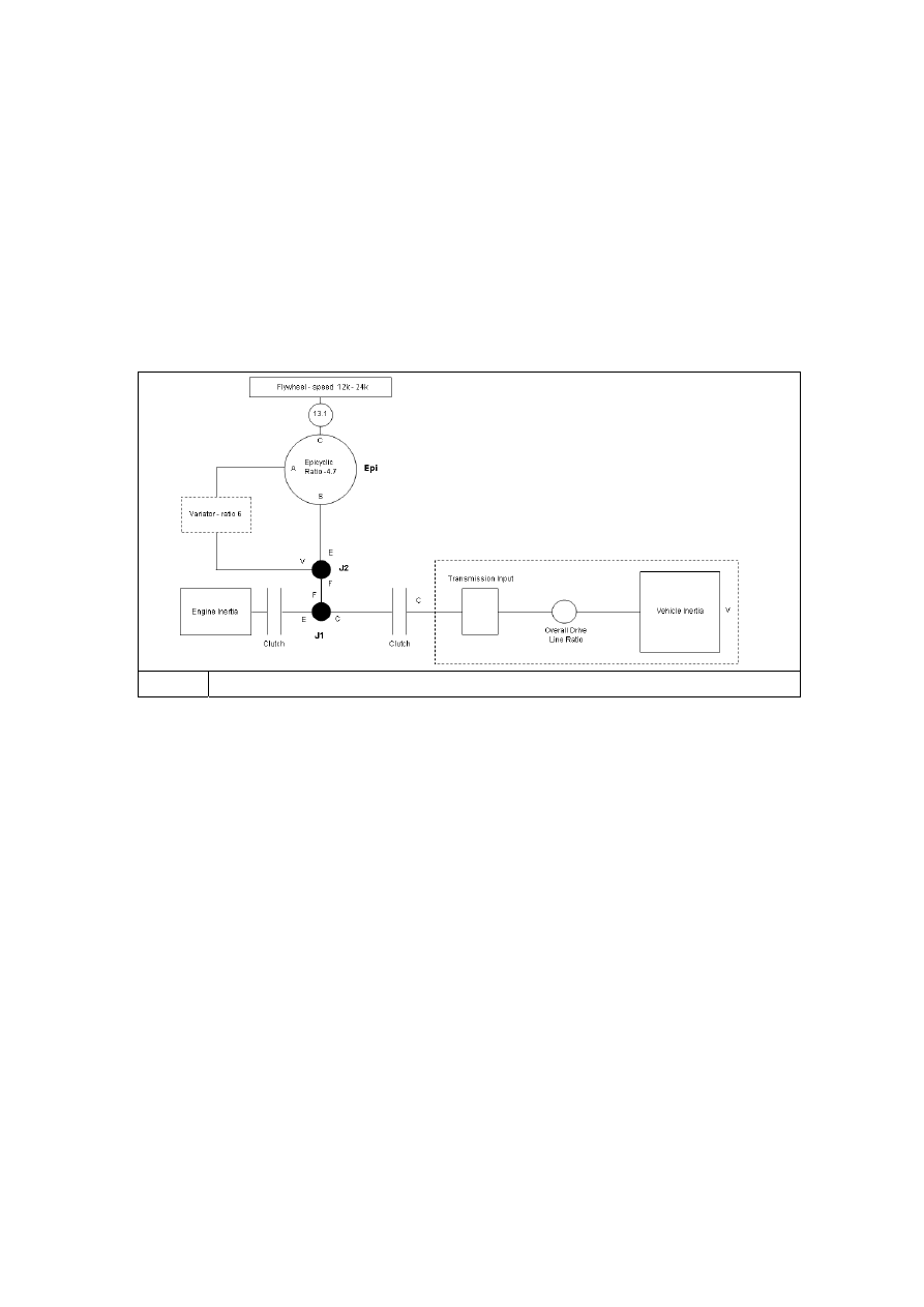
• The Sun gear is connected to the engine and variator input
• The Annulus is connected to the variator output
• The Planet Carrier is connected to the flywheel drive.
Driving the variator at engine speed (through a disconnect / start clutch) and matching the
operating range of the flywheel to the engine, a step up gearing arrangement of 13.1 has
been assumed comprising a two stage gear trains both with a ratio of 3.63:1.
Fig. 5
Assumed Driveline Layout
5.
Road Car Simulation Results
The first item to note regarding the NEDC cycle is that the relatively low vehicle speeds and
gentle accelerations and decelerations together with considerable time spent with the vehicle
stationary and the engine at idle speed. Even though the engine delivers little power during
these phases, it absorbs considerable energy overcoming its inherent motoring losses.
Figure 6 compares the energy dissipated by the engine overcoming its internal losses
(Motoring) with the energy dissipated by the vehicle completing the NEDC cycle (Vehicle
Drive). The first data pair (Engine Only) shows the energy balance for a conventional non-
hybrid driveline. The low performance requirement of the vehicle means that 60% (9 MJ) of
the total energy expended (15 MJ) is dissipated by the engines internal losses. The second
data pair show the energy saved by the addition of regenerative braking (0.64 MJ) derived
from the flywheel and the effect of switching the engine off when not required i.e. when the
flywheel is charging or discharging. Addition of the flywheel enables the marked reduction in
the energy dissipated by the engine (3.5 MJ) resulting in a saving of 20 %.
0
1
2
3
4
5
6
7
8
9
10
Engine Only
KERS
En
ergy
(
M
J)
Vehicle Drive
Motoring Loss
0
1
2
3
4
5
6
7
8
9
10
Engine Only
KERS
En
ergy
(
M
J)
Vehicle Drive
Motoring Loss
Fig. 6
NEDC – Energy Comparison With & Without The Flywheel Hybrid System
Figure 7 plots the vehicle and resulting flywheel speed profiles for the NEDC cycle.
Fig. 7
Flywheel Speed Over the NEDC Cycle
When converted from energy saving to fuel saving, a 30.2% fuel economy improvement
results.
When considering the USA FTP 75 cycle, a similar result is achieved but due to the higher
speed nature with more stop-start events, more energy and hence fuel is saved resulting in
over 40 % benefit compared to the based vehicle.

0
2
4
6
8
10
12
14
Engine Only
KERS
Ener
gy
(
M
J)
Vehicle Drive
Motoring Loss
0
2
4
6
8
10
12
14
Engine Only
KERS
Ener
gy
(
M
J)
Vehicle Drive
Motoring Loss
Fig. 8
FTP 75 – Energy Comparison With & Without The Flywheel Hybrid System
-200.00
-150.00
-100.00
-50.00
0.00
50.00
100.00
0.00
500.00
1000.00
1500.00
2000.00
Time (s)
S
p
eed
(rad
/s
)
Vehicle
Flywheel
Fig. 9
Flywheel Speed Over the FTP75 Cycle
As discussed, the fuel economy is realised by saving energy by ‘engine off’ operation. The
obvious downside of this is a situation common to all ‘engine off’ hybrid systems i.e. lack of
engine driven ancillaries such as air conditioning or power steering. A particularly interesting
point of the mechanical hybrid system is that the flywheel could be used to supply energy to
these systems during the ‘engine off’ period. The fuel economy benefit is, of course,
impacted but the ability to have fuel economy with full ancillary system functionality is a
significant advantage of the mechanical system over other designs.
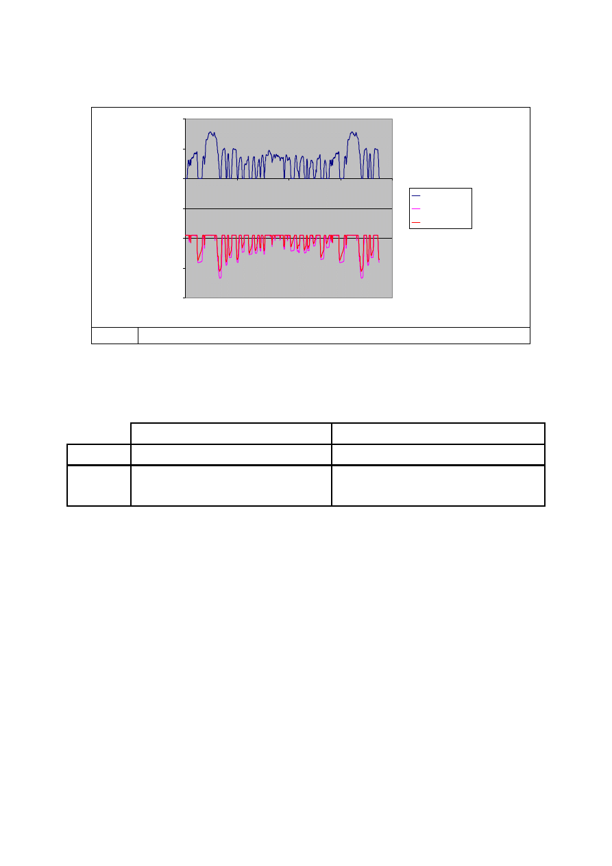
Figure 10 describes the impact on the flywheel speed of also running typical ancillary loads.
-200.00
-150.00
-100.00
-50.00
0.00
50.00
100.00
0.00
500.00
1000.00
1500.00
2000.00
Time (s)
Spe
e
d
(
ra
d
/s
)
Vehicle
Flywheel
Ancillaries
Fig. 10 Flywheel Speed Over the FTP75 Cycle With Ancillary Loading
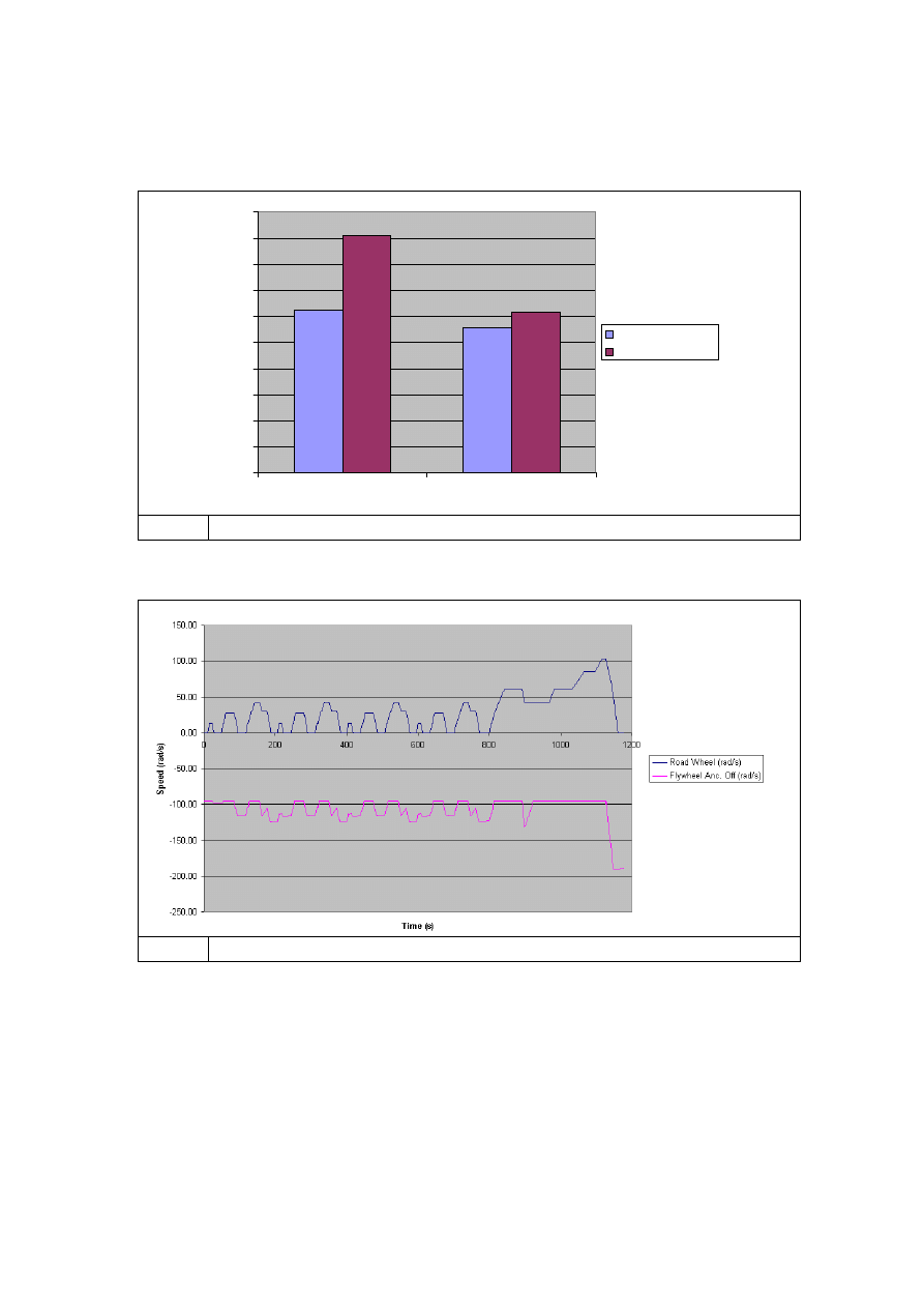
The table below summarises the simulation results for both cycles with and without the
ancillary loading.
ENERGY
FUEL
ECONOMY
Cycle
Flywheel & Engine
With Ancillaries
Flywheel & Engine
With Ancillaries
NEDC 20.3% 9.9% 30.2% 16.2%
FTP75 30.6% 18.2% 42.7%
27.4%
6. Bus
Application
In many ways the city bus represents the best possible application for the KERS principal.
High mass, relatively low rolling resistance and consistent stop start operation provide the
greatest regenerative braking potential.
The model used for the road car analysis has been applied to a ‘generic’ 8500 kg 30 seat city
bus driven by a 110 kW diesel engine through a five speed automatic transmission using a
torque convertor as the engine coupling. The flywheel speed range has been retained at
12,000 rpm to 24,000 rpm but the flywheel inertia has been increased to 0.323 kgm^2 to
enable storage of the kinetic energy of the bus when deceleration from 48 kph (30 mph).
Flywheel power capacity has been assumed to replicate the engine allowing full vehicle

performance when powered by the flywheel. In fact the simulation shows a maximum stored
energy equivalent to 75 % of this value implying only a 600 kJ capacity (50 % higher than the
F1 unit) to be adequate.
The reduced speed range of the diesel engine (500rpm to 2500rpm) provides the opportunity
to reduce the overall ratio spread of the Variator shunt to 9:1 with a consequent reduction in
the recirculating power to 1.07 of the transmitted power (hence improving system efficiency).
The system torques have been reduced by increasing the Variator speed with a 3:1 drive
ratio on the shunt input which allows the flywheel drive ratio to be reduced to 7:1. In this
configuration the operating torque reaction seen by the Variator lies between 300 Nm and
500 Nm requiring a 75 mm roller diameter Variator.
The most significant difference between the bus study and the road car study is the presence
of the torque convertor. Typical bus operation does not apply the lockup clutch until third
gear. The resulting degradation in driveline efficiency would effectively prevent flywheel
charge in the first two gears. However the flywheel acts as a constant power source at any
transmission input speed. Fluid coupling torque multiplication is not therefore required. The
transmission shift schedule is therefore modified to lock the convertor when possible and
when operating on the flywheel at all conditions other than launch in first gear.
Given the power capacity of the flywheel and the inherent torque control of the Variator, this
will neither reduce vehicle performance nor degrade driveline smoothness.
As for the road car application, it is essential to reduce parasitic fuel consumption by
moderating engine operation while the flywheel drives. However the ancillary load for a large
passenger vehicle is likely to be significant and must include a pneumatic load for brakes and
suspension as well as air conditioning or heating. Engine drive of the ancillary load has
therefore been assumed at all times. Flywheel operation will therefore disconnect the engine
from the driveline but keep it operating at or near idle speed.
8.
Bus Application Results
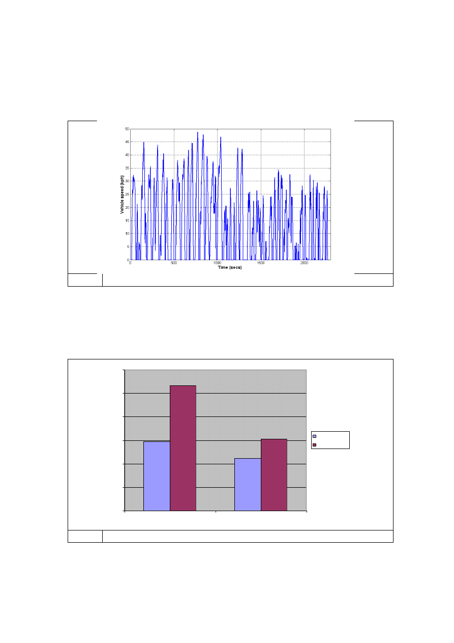
The simulation has used the official UK ‘MLTB ‘59’ bus drive cycle
Fig. 11 MTLB 159 Bus Cycle
The energy comparison plot shows that, unlike the road car application, the engine motoring
loss of 15 MJ is significantly less than the energy supplied to the vehicle (26.5 MJ). Hence
the energy saving due to energy recovery is significant at 36%.
0
5
10
15
20
25
30
Engine Only
Flywheel Enabled
En
e
rg
y
(
M
J
)
Motoring
Vehicle Drive
Fig. 12 MLTB 159 Energy Comparison With & Without The Flywheel Hybrid System
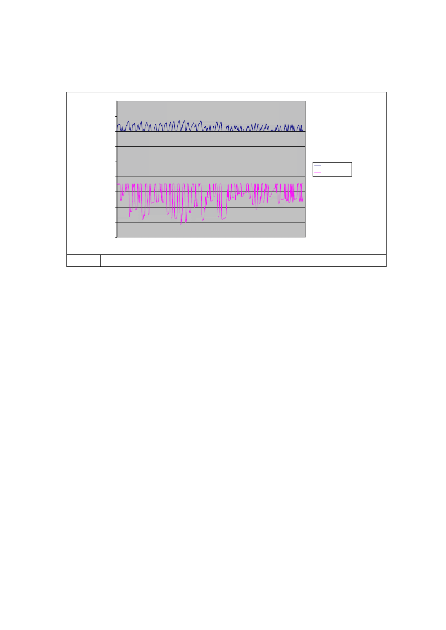
Overall the 36% energy saving delivered by the KERS unit equates to a 34% fuel saving in
the 8,500kg diesel engined bus application.
-350
-300
-250
-200
-150
-100
-50
0
50
100
0
500
1000
1500
2000
Time (s)
Speed
(rad
/s
)
Road Wheel
Flywheel
Fig. 13 Flywheel Speed Over the MLTB 159 Cycle
9. Summary
A mechanical hybrid has been realised providing 400 kJ at 60 kW for introduction in the 2009
Formula 1 race season. The system comprises a mechanical flywheel as the storage
medium and a Torotrak full-toroidal traction drive system as the transmission.
The transmission is based upon Torotrak’s standard automotive specification of materials
and traction fluids and utilises a 5 kg, 55 mm roller diameter variator.
Mechanical hybrid systems for road car and bus applications are being developed as the
energy, fuel economy and performance benefits, as well as the cost, weight and package
advantages, of the mechanical hybrid are clear.
Chris Brockbank
Torotrak (Development) Ltd
Wyszukiwarka
Podobne podstrony:
A Sarong in my Backpack Adventures from Munich to Pushkar
Techniki Transmisji i Systemy?zprzewodowe
~$chniki Transmisji i Systemy Bezprzewodowe doc
G 2 0 DOHC Automatic Transmission System doc
G 2 0 DOHC Manual Transmission System doc
Kwiek, Marek From System Expansion to System Contraction Access to Higher Education in Poland (2014
D Stuart Ritual and History in the Stucco Inscription from Temple XIX at Palenque
System informatyczny jest to zbior powiazanych zesoba elementow
finanse międzynarodowe Blichowska, test finanse międzynarodowe zaoczne, Pierwszy kraj, w którym wpro
Adaptive Filters in MATLAB From Novice to Expert
systemy, sciaga na systemy, Paliwo umowne to hipotetyczne paliwo mające wartość opałową ok
Notto R Thelle Buddhism and Christianity in Japan From Conflict to Dialogue, 1854 1899, 1987
Patterns of damage in genomic DNA sequences from a Neandertal
64. Team Attacking in the Attacking 1-3 – Attacking from cen, Materiały Szkoleniowe Łukasz, uefa b k
D Stuart Ritual and History in the Stucco Inscription from Temple XIX at Palenque
Vladigerov[1] In modo bulgaro No 2 from 6 Preludes exotiques Op 17
Far Infrared Energy Distributions of Active Galaxies in the Local Universe and Beyond From ISO to H
ebooksclub org Women and Race in Contemporary U S Writing From Faulkner to Morrison American Literat
więcej podobnych podstron