Optimum absorber temperature of a once-reflecting
full conical concentrator of a low temperature
differential Stirling engine
Bancha Kongtragool, Somchai Wongwises*
Fluid Mechanics, Thermal Engineering and Multiphase Flow Research Labarotary (FUTURE),
Department of Mechanical Engineering, King Mongkut’s University of Technology,
Thonburi, Bangmod, Bangkok 10140, Thailand
Received 13 August 2004; accepted 12 January 2005
Available online 25 February 2005
Abstract
This paper provides a theoretical investigation on the optimum absorber temperature of a once-
reflecting full conical concentrator for maximizing overall efficiency of a solar-powered low
temperature differential Stirling engine. A mathematical model for the overall efficiency of the solar-
powered Stirling engine is developed. The optimum absorber temperature for maximum overall
efficiency for both limiting conditions of maximum possible engine efficiency and maximum
possible engine power output is determined. The results indicated that the optimum absorber
temperatures calculated from these two limiting cases are not significantly different. For a given
concentrated solar intensity, the maximum overall efficiency characterized by the condition of
maximum possible engine power output is very close to that of the real engine of 55% Carnot
efficiency, approximately.
q
2005 Published by Elsevier Ltd.
Keywords: Stirling engine; Solar-powered heat engine; Conical concentrator
Renewable Energy 30 (2005) 1671–1687
www.elsevier.com/locate/renene
0960-1481/$ - see front matter q 2005 Published by Elsevier Ltd.
doi:10.1016/j.renene.2005.01.003
* Corresponding author. Tel.: C662 4709115; fax: C662 4709111.
E-mail address: somchai.won@kmutt.ac.th (S. Wongwises).

Nomenclature
A
O
cone opening area in m
2
A
H
absorber area or heater convection heat transfer area (m
2
)
C
concentration factor
C
1
, C
2
the factors representing the performance of the two ways of energy
collection of the conical concentrator, defined by Eqs. (5), (6), (12)
and (13)
E
overall efficiency
E
C
concentrator efficiency
E
E
engine efficiency
E
IT
indicated thermal efficiency
E
Carnot
complete reversible Carnot efficiency
E
Curzon–Ahlborn
Curzon–Ahlborn efficiency
E
Endo-reversible
endo-reversible Carnot-like engine efficiency
Ff
incidence angle reduced factor
h
H
heater convection heat transfer coefficient (W/m
2
K)
I
direct solar flux intensity (W/m
2
)
K
S
Stirling coefficientZE
IT
/E
Carnot
K
1
a constant, defined by Eq. (30)
K
2
a constant, defined by Eq. (31)
q
total energy received by the absorber plate (W)
q
CH
convection loss (W)
q
in
useful energy (W)
q
RH
radiation loss (W)
q
S
total solar energy input to the concentrator (W)
R
radius of the cone opening (m)
R
radius of the absorber plate (m)
T
A
ambient temperature (K)
T
C
engine cooler temperature (K)
T
H
absorber or engine heater temperature (K)
*T
H
optimum absorber temperature (K)
T
Sky
sky temperature (K)
T
1
the cold-side working fluid temperature (K)
T
3
hot-side working fluid temperature (K)
Greek letters
a
absorptivity of absorber plate
3
emissivity of the absorber plate
f
cone included angle in degrees, used in Eq. (7)
r
reflectivity of reflector
s
Stefan–Boltzmann constant, 5.667!10
K
8
W/(m
2
K
4
)
t
transmissivity of cover plate
B. Kongtragool, S. Wongwises / Renewable Energy 30 (2005) 1671–1687
1672
1. Introduction
Solar energy is an attractive renewable energy source that can be used as an input
energy source for heat engines. In fact, any heat energy source can be used in a Stirling
engine. The solar radiation can be focused onto the displacer hot-end of the Stirling
engine, thereby creating a solar-powered prime mover. The direct conversion of solar
power into mechanical power reduces both the cost and complexity of the prime mover.
When a solar collector is used as a heat input source of a heat engine for power
generation, one of the design objectives is to optimize the overall system performance. In
general, the collector works best at low temperatures and its efficiency decreases with
increasing temperature. However, the heat engine is most efficient with heat input at high
temperatures and its efficiency increases with increasing temperature.
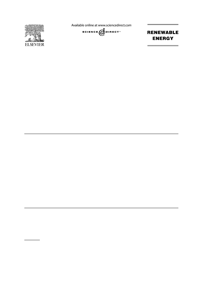
The overall efficiency of the direct solar-powered heat engine is the product of the solar
collector efficiency and the heat engine efficiency. The dependence of the collector,
engine, and system efficiency on temperature is shown in
. This contrary
temperature-efficiency relationship indicates that any solar-powered heat engine will have
an optimum absorber temperature. Therefore, in solar-powered heat engine design there is
a need to know the optimum absorber temperature in order to operate the system at its
maximum overall efficiency.
The optimum solar collector temperature has been studied by many researchers. Many
works on low temperature differential (LTD) Stirling engines and solar-powered Stirling
engines including technology and optimization have been investigated in the authors’
former works
. Among many researches, some closely related works are as follows:
In 1977, Howell and Bannerot
determined the optimum value of the outlet
temperature of the solar collector to maximize the work output of idealized Carnot,
Stirling, Ericsson, and Brayton engines powered by a solar collector. Their mathematical
model is formulated by using a ratio of useful energy provided by the collector to
Fig. 1. Typical temperature-efficiency relationship of solar-power heat engine.
B. Kongtragool, S. Wongwises / Renewable Energy 30 (2005) 1671–1687
1673

the absorbed solar energy and a ratio of the useful work to the absorbed solar energy. Heat
losses from collector were both the radiation and convection heat loss. For Stirling engine
efficiency, the formula for an imperfect regeneration Stirling cycle was used. However, in
their analysis the hot-side working fluid temperature was the heater temperature and the
cold-side working fluid temperature was the cooler temperature approximated as an
ambient temperature.
In 1988, Gordon
examined the accuracy of the energy optimization of solar-
driven heat engines. The results were obtained for the two limiting cases of maximum
efficiency and maximum power. The effect of radiation and convection heat loss was
studied separately; the Carnot and Curzon–Ahlborn efficiencies were used in the
analysis.
In 1993, Eldighidy
used the same concept as Howell and Bannerot
to
theoretically investigate the optimum outlet temperatures of the solar collector for
maximum work output for an ideal regeneration air-standard Otto cycle. The effect of
radiation and convection loss from the collector on the optimum outlet temperature was
shown. Idealized air-standard cycle efficiency was used in analysis. However, in his
analysis the temperature difference between the absorber and the hot-side working fluid of
5 K was assumed.
In 1996, Chen, Sun and Wu
presented the optimum collector temperature for solar-
powered heat engines. Four conditions of collector heat loss are modeled with Carnot and
Curzon–Ahlborn efficiencies. However, the application on their models was not shown in
the paper.
Although many researchers have studied the optimum solar collector temperature, there
still remains room for study on Stirling engines operating at low temperatures. LTD
Stirling engine powered by a once-reflecting full conical concentrator is one that has
received little attention in literature and should be studied in detail.
This article is a theoretical investigation on the optimum absorber temperature required
for a LTD Stirling engine to operate at its maximum overall efficiency. The aim of this
article is to provide the basis for the design of a real solar-powered LTD Stirling engine
operated with a low cost concentrator.
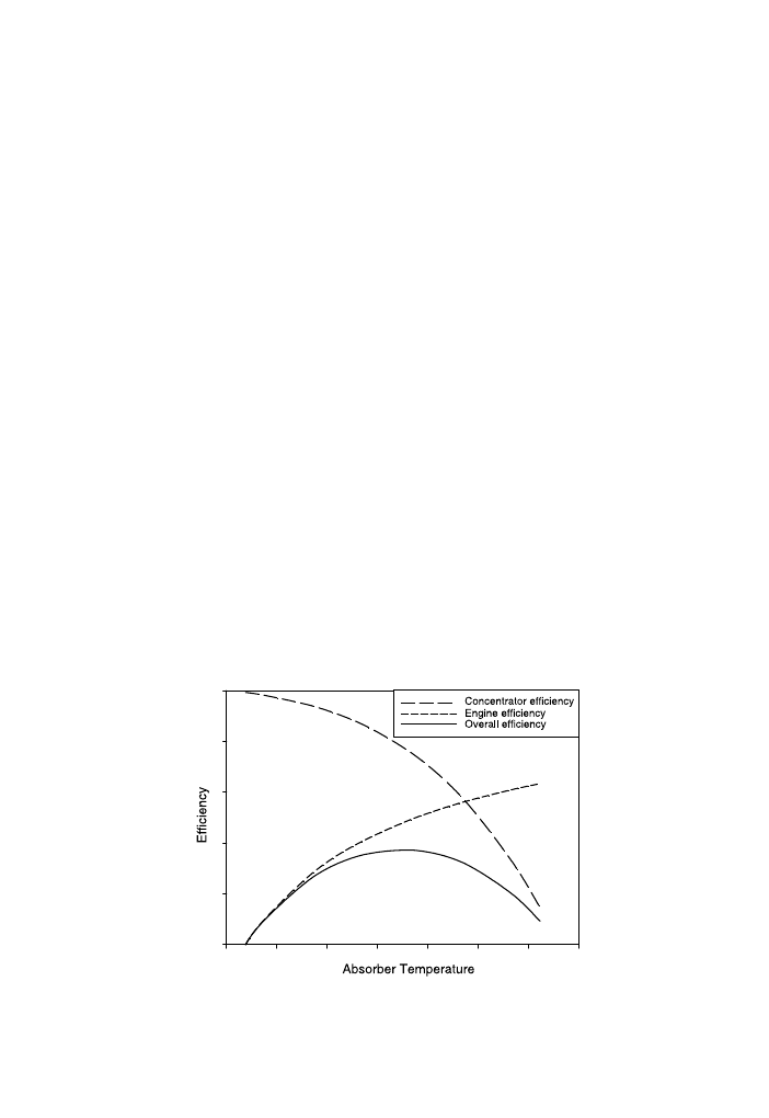
2. Mathematical model
A schematic diagram of a solar-powered Stirling engine is shown in
. The analysis
of the problem includes the mathematical models for the solar concentrator, Stirling
engine, and the combination of solar collector and Stirling engine. These models are
described as follows:
2.1. Solar collector
In principle, both the concentrating and non-concentrating solar collector can be used to
power the Stirling engine. Since the practical temperature limit of the flat-plate collector is
around 100 8C above the ambient temperature
, a more efficient Stirling needs a
concentrating collector
B. Kongtragool, S. Wongwises / Renewable Energy 30 (2005) 1671–1687
1674
The concentrator considered is limited to a reflector, called the once-reflecting
cone, which can be characterized in that every sunray entering parallel to the axis and
striking the cone is reflected directly on the absorber plate only. This configuration
reduces the cone length, minimizes reflection losses, and is most allowing for
focusing errors
. The following analysis is applied to the condition that the cone
axis is always parallel to the sunrays. Once-reflecting full conical reflector is a cone
where,
R Z rð1 C 2 cos fÞ
(1)
where R is radius of the cone opening in m, r is radius of the absorber plate in m,
and f is cone included angle in degrees.
The total solar energy input to the concentrator is given by
q
S
Z IA
O
(2)
where I is direct solar flux intensity in W/m
2
, and A
O
is cone opening area in m
2
.
For a sunray entering parallel to the cone axis, the solar power concentrated onto the
absorber plate with a transparent cover is given by
Concentrated solar power, qZDirect radiation onto absorberCReflected radiation by
cone onto absorber
q Z IA
H
C
1
C
IðA
O
K
A
H
ÞC
2
(3)
q Z C
1
Ipr
2
C
C
2
IpðR
2
K
r
2
Þ
(4)
where q is total power absorbed by the absorber plate in W, A
H
is absorber area in m
2
, C
1
is
the factor representing direct radiation onto absorber, and C
2
is the factor representing
reflected radiation by cone onto absorber.
Fig. 2. Schematic diagram of a solar-powered Stirling engine.
B. Kongtragool, S. Wongwises / Renewable Energy 30 (2005) 1671–1687
1675
The factor C
1
depends on the transmissivity of the cover and the absorptivity of the
absorber plate. The factor C
2
is product between the reflectivity of the reflector, incidence
angle reduced factor, and the combined transmissivity and absorptivity of the absorber.
C
1
Z at
(5)
C
2
Z atrðFfÞ
(6)
where a is absorptivity of absorber plate, t is transmissivity of absorber plate, r is
reflectivity of reflector and Ff is incidence angle reduced factor
:
Ff Z K1:06332 !10
K
9
f
3
C
0
:396!10
K
6
f
2
K
48
:86922!10
K
6
f C 0
:9217
(7)
Eq. (4) can be written as:
q Z Ipr
2
½C
1
C
4C
2
cos fð1 C cos fÞ
(8)
The concentrating factor, C, is defined as:
C Z q=Ipr
2
Z ½C
1
C
4C
2
cos fð1 C cos fÞ
(9)
Then
q Z Ipr
2
C Z IA
H
C
(10)
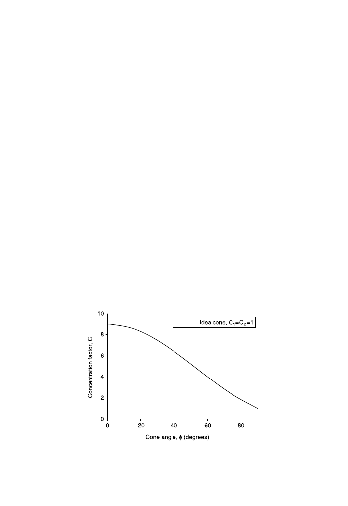
For ideal cone, C
1
ZC
2
Z1, Eq. (9) give the interesting fact that the concentration
factor has a limiting value of CZ9 as the cone vertex angle approaches zero, as
shown in
. As the concentration factor approaches 9, cone length increases
without bound. However, ideal concentration factors of up to about 7 can be obtained
with cones of practical length to diameter ratio
. For ideal cone the concentration
factor can be determined from:
C Z A
O
=A
H
Z ð1 C 2 cos fÞ
2
(11)
Fig. 3. Ideal concentrating factor of once-reflecting full conical reflector, calculated from Eq. (9).
B. Kongtragool, S. Wongwises / Renewable Energy 30 (2005) 1671–1687
1676

The following analysis is applied to an opaque absorber. For an opaque absorber,
the factor C
1
and C
2
can be determined from:
C
1
Z a
(12)
C
2
Z arðFfÞ
(13)
Then, the previous equations for an absorber with a transparent cover can be
applied to an opaque absorber by using the appropriate factor C
1
and C
2
.
In general, disregard the heat transmission through the cone wall, the energy balance of
an absorber plate is
:
Useful energy collected, q
in
ZConcentrated solar energy, qKRadiation loss, q
RH
K
convection loss, q
CH
Suppose that the absorber plate operates at a temperature of T
H
. Howell and Bannerot
and Brinkworth
proposed the radiation loss in a simple form:
q
RH
Z 3sA
H
T
4
H
(14)
where s is the Stefan–Boltzmann constant, 5.667!10
K
8
W/m
2
K
4
, 3 is the emissivity
of the absorber plate. Eldighidy
presented the radiation loss in a more complicated
form
q
RH
Z 3sA
H
T
4
H
K
T
4
Sky
(15)
where
T
Sky
Z 0:0552T
1
:5
A
(16)
where T
A
is the ambient temperature, therefore, Eq. (15) becomes:
q
RH
Z 3sA
H
T
4
H
K
9
:2845!10
K
6
T
6
A
(17)
It should be noted that, if T
A
Z35 8CZ308 K, T
Sky
Z298 KZ0.97T
A
. However, Kreith
and Kreider
and Chen et al.
proposed the radiation loss in a simpler form:
q
RH
Z 3sA
H
T
4
H
K
T
4
A
(18)
Several researchers
have proposed the convection loss in the form
q
CH
Z h
H
A
H
ðT
H
K
T
A
Þ
(19)
where h
H
is the heater convection heat transfer coefficient and A
H
is the heater convection
heat transfer area. Brinkworth
suggested the value of h
H
Z4 W/m
2
K for still air and
h
H
Z30 W/m
2
K for the wind velocity of 10 m/s.
If Eqs. (18) and (19) are used to represent the radiation and convection loss, then, the
useful energy collected in a general case of absorber heat loss is:
q
in
Z IA
H
C K 3sA
H
T
4
H
K
T
4
A
K
h
H
A
H
ðT
H
K
T
A
Þ
(20)
In the case of a collector with a high concentration factor, many researchers have made
analyses by considering the main part of energy losses to the environment heat sink to
occur only by radiation
B. Kongtragool, S. Wongwises / Renewable Energy 30 (2005) 1671–1687
1677
The concentrator efficiency is the ratio of the useful collected energy to the solar energy
input:
E
C
Z q
in
=q
S
(21)
Substitute Eqs. (2) and (20) in Eq. (21):
E
C
Z ½IA
H
C K 3sA
H
ðT
4
H
K
T
4
A
Þ K h
H
A
H
ðT
H
K
T
A
Þ
=IA
O
(22)
For ideal cone, A
O
ZA
H
C, then the concentrator efficiency can be determined from:
E
C
Z 1 K ½3s=ðICÞðT
4
H
K
T
4
A
Þ K ½h
H
=ðICÞðT
H
K
T
A
Þ
(23)
2.2. Stirling engine
The Stirling engine in general is well suited to the solar applications
. The most
critical aspect of a solar-powered engine is the design of the solar collector for the engine.
If the absorber (that acts as the displacer cylinder head) cannot effectively give the
required heat input then the desired engine power output and efficiency will not be
obtained.
Heat engines are usually designed to operate at a point between two limiting cases of
practical interest, the maximum possible efficiency and the maximum possible power
output. The first limiting case is the Carnot efficiency of the complete reversible heat
engine, which represents the maximum engine efficiency. The second limiting case is the
Curzon–Ahlborn efficiency of the endo-reversile heat engine that represents the efficiency
at the operation of the maximum power output.
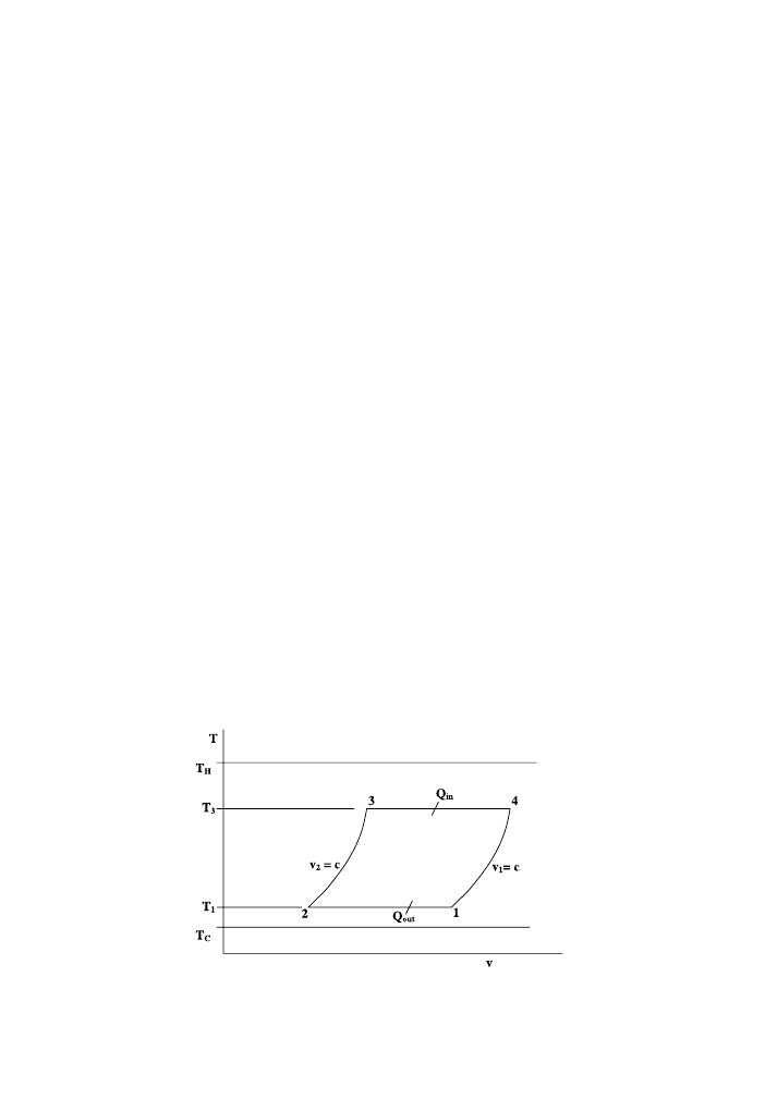
The complete reversible Carnot efficiency is given by
E
Carnot
Z 1 K T
C
=T
H
(24)
where T
C
is the engine cooler temperature in K (see
). To reach the complete
reversible Carnot efficiency, the isothermal heating and cooling processes must be
infinitely slow enough to ensure that the thermal equilibrium between working fluid and its
Fig. 4. T-s diagram for Stirling cycle.
B. Kongtragool, S. Wongwises / Renewable Energy 30 (2005) 1671–1687
1678

heat source or heat sink occurred. Since as infinite period of time is required to get a finite
amount of work, the engine power output then approaches zero.
In the endo-reversible heat engine, the two heat transfer processes from the heat
source and to the heat sink are considered to be the only irreversible processes in the
cycle
. In Carnot-like engines the heat exchange between the working fluid and
heat source and heat sink is isothermal or near-isothermal
. The Stirling engine is a
Carnot-like engine. The endo-reversible Carnot-like engine efficiency is lower than the
complete reversible Carnot engine efficiency, however it produces useful power
output. The endo-reversible Carnot-like engine efficiency is given by
E
Endoreversible
Z 1 K T
1
=T
3
(25)
where T
1
is the cold-side working fluid temperature in K, T
3
is the hot-side working
fluid temperature in K. Curzon and Ahlborn
were the first to derive the endo-
reversible Carnot-like engine efficiency under the condition of maximum power
output. The Curzon–Ahlborn efficiency is given by
E
Curzon – Ahlborn
Z 1 K ðT
C
=T
H
Þ
0
:5
(26)
Curzon–Ahlborn efficiency does not represent an upper limit on real heat engine
efficiency; however, it only represents an upper limit on real heat engine efficiency
under the condition of maximum power output
.
For a real Stirling engine, the engine efficiency expression can be found in a
simple form from the Malmo formula
E
IT
Z K
S
ð1 K T
C
=T
H
Þ
(27)
where K
S
is the Stirling coefficient, the ratio of indicated thermal efficiency to Carnot
efficiency. K
S
is the proportion of the ideal Stirling cycle efficiency that can be
obtained with the present technology
. The value of K
S
will be found in the range
of 0.55–0.88 (K
S
Z0.55–0.88)
. For well optimized hydrogen engines operated at
their maximum efficiency points, K
S
is 0.65–0.75, and under special conditions, K
S
Z
0.8
.
Other works related to K
S
are scarce. However, Brinkworth
analyzed the overall
efficiency of a solar-powered Stirling engine by using an engine efficiency of 50% of the
Carnot efficiency. Likewise, for Stirling engine design, Walker
suggested an engine
efficiency of 50% of the Carnot efficiency.
2.3. Solar-powered stirling engine
For a solar-powered Stirling engine system consisting of a once-reflecting full conical
concentrator and a Stirling engine, the overall efficiency is given by:
E Z E
C
E
E
(28)
Rearrange Eq. (23) as
E
C
Z 1 K K
1
ðT
4
H
K
T
4
A
Þ K K
2
ðT
H
K
T
A
Þ
(29)
B. Kongtragool, S. Wongwises / Renewable Energy 30 (2005) 1671–1687
1679

where
K
1
Z ½3s=ðICÞ
(30)
K
2
Z ½h
H
=ðICÞ
(31)
Then, Eq. (28) becomes:
E Z ½1 K K
1
T
4
H
K
T
4
A
K
K
2
ðT
H
K
T
A
ÞE
E
(32)
The limiting expressions for the two limits of maximum possible efficiency and
maximum possible power output can be formulated by substituting Eqs. (24) and (26) into
Eq. (32). Assuming that the engine design operating temperature falls between these two
limits, the optimal operating temperature should also lie between the optimal temperatures
determined from these two limiting cases.
It should be noted that the Carnot efficiency is significantly greater than the real engine
efficiency; therefore, the overall efficiency calculated with the Carnot efficiency is also
much greater than that of the real engine
2.3.1. The condition of maximum possible efficiency
Substitution of Eq. (29) into Eq. (32) gives
E Z E
C
E
Carnot
Z ½1 K K
1
ðT
4
H
K
T
4
A
Þ K K
2
ðT
H
K
T
A
Þ½1 K T
C
=T
H
(33)
To maximizing the overall efficiency, take the derivative of the overall efficiency with
respect to the absorber temperature and equate it to zero, dE/dT
H
Z0, the optimum
absorber temperature, *T
H
, for this condition can be obtained from:
T
5
H
K
0
:75T
C
T
4
H
C ½
0
:25ðK
2
=K
1
Þ T
2
H
K
0
:25½T
4
A
C ð
K
2
=K
1
ÞT
A
C
1
=K
1
T
C
Z 0
(34)
2.3.2. The condition of maximum possible power output
Substitution of Eq. (26) into Eq. (32) gives:
E Z E
C
E
CurzonAhlborn
Z ½1 K K
1
ðT
4
H
K
T
4
A
Þ K K
2
ðT
H
K
T
A
Þ½1 K ðT
C
=T
H
Þ
0
:5
(35)
In the same manner, the optimum absorber temperature for the second condition can be
found as:
T
9
=2
H
K
0
:875T
0
:5
C
T
4
H
C
0
:25ðK
2
=K
1
Þ T
3
=2
H
K
0
:125ðK
2
=K
1
ÞT
0
:5
C
(36)
T
H
K
0
:125½T
4
A
C ð
K
2
=K
1
ÞT
A
C
1
=K
1
T
0
:5
C
Z 0
2.3.3. Real Engine
Substitution of Eq. (27) into Eq. (32) gives:
E Z E
C
E
E
Z ½1 K K
1
ðT
4
H
K
T
4
A
Þ K K
2
ðT
H
K
T
A
Þ½K
S
ð1 K T
C
=T
H
Þ
(37)
B. Kongtragool, S. Wongwises / Renewable Energy 30 (2005) 1671–1687
1680

It can be seen that Eq. (37) is the same as Eq. (33), except for the constant K
S
. In this
case, therefore, the same optimum absorber temperature as the case of maximum possible
efficiency will be achieved.
2.4. Solution method
Some typical values for the emissivity 3
H
, the convection heat transfer coefficient h
H
,
the ideal concentration factor C, and the solar flux intensity I, are needed in the
calculations. The cooler temperature T
C
and the ambient temperature T
A
are also needed as
input data in this calculation. The steps in calculation are as follows:
Step 1 Calculate the optimum absorber temperatures: The optimum absorber tempera-
tures for maximizing overall efficiency at various concentrated solar intensity, IC,
can be determined from Eqs. (34) and (36).
Step 2 Calculate the concentrator efficiencies: The concentrator efficiencies at maximum
overall efficiency calculated from Eq. (23) by using the optimum absorber
temperatures obtained from step 1.
Step 3 Calculate the engine efficiencies: Engine efficiency at maximum possible power
output operation is calculated from Eq. (26) with the optimum absorber
temperature calculated from Eq. (36). The real engine efficiency is calculated
from Eq. (27) by using K
S
Z0.5 with the optimum absorber temperature calculated
from Eq. (34).
Step 4 Calculate the overall efficiencies: The overall efficiencies are the products of the
concentrator efficiencies obtained in step 2 and the engine efficiency obtained in
step 3.
3. Results and discussion
The results presented are based on some typical values for radiation and convection
parameters; 3Z0.39, sZ5.667!10
K
8
W/m
2
K
4
, and h
H
Z4 W/m
2
K. The ideal
concentration factor is fixed at the practical limit of CZ7. The solar flux intensities
in the range of 100–1000 W/m
2
, with increments in steps of 100 W/m
2
, are used in the
calculations. All calculations assumed an absorber area of 1 m
2
and an ambient
temperature of T
A
Z35 8C. The cooler temperatures of T
C
Z45, 55, and 65 8C are used
in this study.
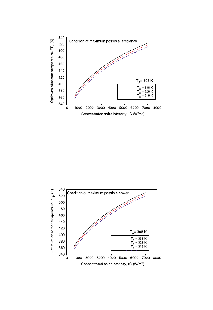
The optimum absorber temperatures for maximizing overall efficiency at various
concentrated solar intensity, IC, are shown in
, respectively. It can be seen that
the optimum absorber temperature for both limiting cases increases with increasing
concentrated solar intensity and cooler temperature.
As shown in
, the optimum absorber temperature in the condition of maximum
possible power output is slightly greater than the case of maximum possible efficiency.
The difference in optimum absorber temperature for these two limiting cases also
increases with an increasing concentrated solar intensity. However, this difference in
optimum absorber temperature is not significance since its value is only a few percentages.
B. Kongtragool, S. Wongwises / Renewable Energy 30 (2005) 1671–1687
1681
Therefore, either the condition of maximum possible efficiency or the condition of
maximum possible power output can serve as a basis for calculating the optimum absorber
temperature.
For a given cooler temperature, the optimum absorber temperature with the
concentrator, engine and overall efficiency can be plotted against the concentrated solar
intensity as shown in
. To clarify examine the effects of the cooler temperature on
these efficiencies; these efficiencies at various cooler temperatures are separately plotted
against the concentrated solar intensity.
Fig. 5. Optimum absorber temperature against concentrated solar intensity in case of maximum possible
efficiency (and also real engine).
Fig. 6. Optimum absorber temperature against concentrated solar intensity in case of maximum possible power
output.
B. Kongtragool, S. Wongwises / Renewable Energy 30 (2005) 1671–1687
1682
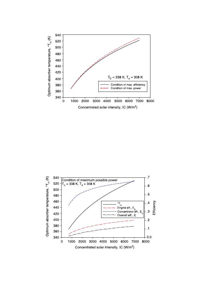
The concentrator efficiencies at maximum overall efficiency calculated from the
optimum absorber temperatures of both limiting conditions are shown in
. It can be
seen from this figure that the concentrator efficiency increases with increasing
concentrated solar intensity and with decreasing cooler temperature. Since the optimum
absorber temperature for maximizing overall efficiency in the case of maximum possible
power output is higher than that of the maximum possible efficiency, then, the concentrator
efficiency in the case of maximum possible power output is lower than in the case of
Fig. 7. Optimum absorber temperature against concentrated solar intensity, comparison between two limiting
cases.
Fig. 8. Optimum absorber temperature and efficiencies against concentrated solar intensity in case of maximum
possible power output.
B. Kongtragool, S. Wongwises / Renewable Energy 30 (2005) 1671–1687
1683
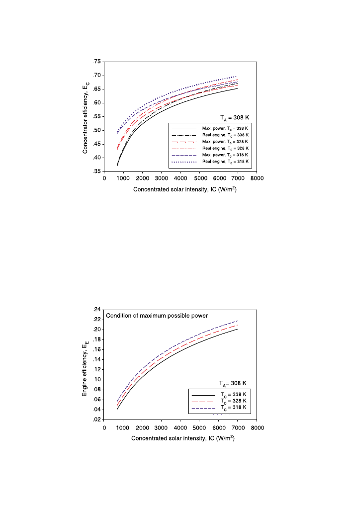
maximum possible efficiency. The concentrator efficiency in the case of maximum
possible efficiency is used to represent the collector efficiency of the real engine.
showed relationships between engine efficiency at maximum overall efficiency
and concentrated solar intensity in a condition of maximum possible power. It is evidenced
that, for all curves, the engine efficiency increases with increasing concentrated solar
intensity. The higher engine efficiency can be obtained by using lower cooler temperature.
To compare the condition of maximum possible power with a real engine, the
relationships between engine efficiency at maximum overall efficiency and concentrated
Fig. 9. Concentrator efficiency against concentrated solar intensity, comparison between a case of maximum
possible power output and real engine.
Fig. 10. Engine efficiency against concentrated solar intensity in case of maximum possible power output.
B. Kongtragool, S. Wongwises / Renewable Energy 30 (2005) 1671–1687
1684
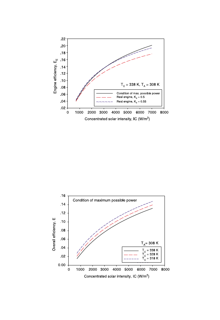
solar intensity in a condition of maximum possible power and real engines of K
S
Z0.5 and
0.55 are shown in
. It can be seen that the engine efficiency in the case of maximum
possible power output is very closed to that of the real engine of K
S
Z0.55.
The relationships between the maximum overall efficiency and concentrated solar
intensity are shown in
. For all curves, the maximum overall efficiency increases
with an increasing concentrated solar intensity. The overall efficiency also increases with
decreasing cooler temperature.
Fig. 11. Engine efficiency against concentrated solar intensity, comparison between a case of maximum possible
power output and real engines of K
S
Z0.5 and 0.55.
Fig. 12. Overall efficiency against concentrated solar intensity in case of maximum possible power output.
B. Kongtragool, S. Wongwises / Renewable Energy 30 (2005) 1671–1687
1685
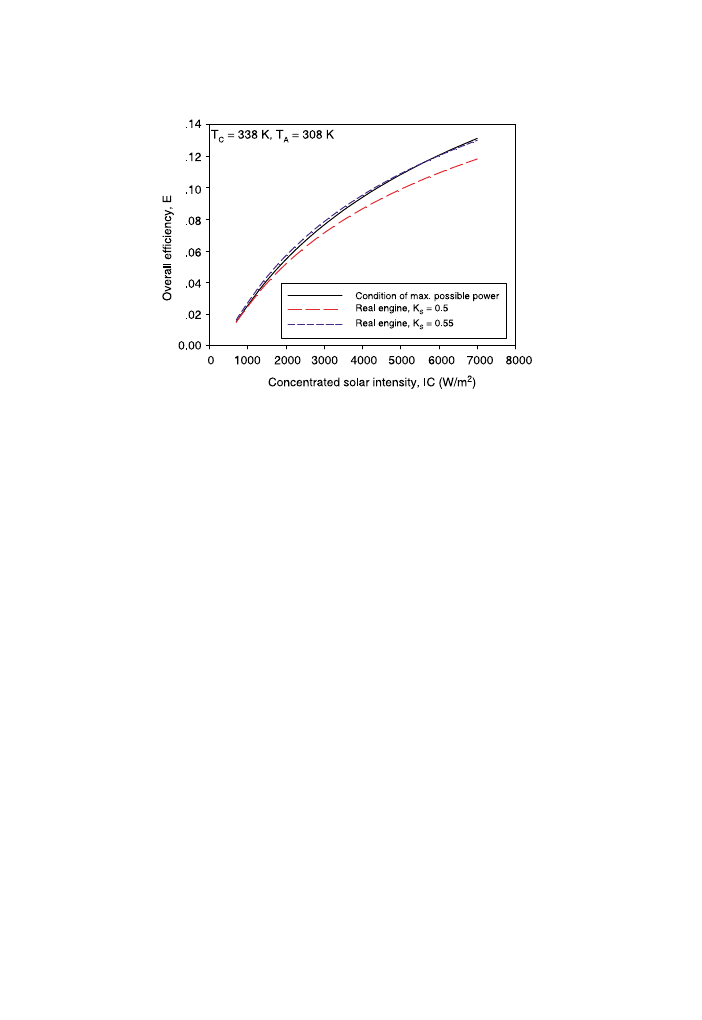
To compare the condition of maximum possible power with a real engine, the
maximum overall efficiency in the condition of maximum possible power and real engines
of K
S
Z0.5 and 0.55 are plotted against the concentrated solar intensity as shown in
. It can be noted that the curve of the condition of maximum power is much closer to
that of the real engine of K
S
Z0.55.
4. Conclusions
This work provides a theoretical investigation on the optimum absorber temperature of
a once-reflecting full conical solar concentrator for maximizing overall efficiency of a
solar-powered LTD Stirling engine. A mathematical model for the overall efficiency of a
Stirling engine powered by an ideal cone in the general case of absorber heat loss is
developed. Two limits of maximum possible engine efficiency and maximum possible
engine power output are studied. The optimum absorber temperature for maximum overall
efficiency for both limiting conditions is determined. The maximum overall efficiency in
the condition of maximum possible power output is compared to that of a real engine.
From this study, the following conclusions can be drawn:
1. The results indicate that the optimum absorber temperatures calculated from the
condition of maximum possible efficiency and the condition of maximum possible
power output are not significantly different.
2. The optimum absorber temperature will increase with increasing concentrated solar
intensity and will decrease with decreasing cooler temperature.
3. The maximum overall efficiency will increased with increasing concentrated solar
intensity and decreasing cooler temperature.
Fig. 13. Overall efficiency against concentrated solar intensity, comparison between a case of maximum possible
power output and real engines of K
S
Z0.5 and 0.55.
B. Kongtragool, S. Wongwises / Renewable Energy 30 (2005) 1671–1687
1686

4. For a given concentrated solar intensity, the maximum overall efficiency calculated
from the condition of maximum possible power output is very close to that of the real
engine of K
S
Z0.55.
Acknowledgements
The authors would like to express their appreciation to the Joint Graduate School of
Energy and Environment (JGSEE) and the Thailand Research Fund (TRF) for providing
financial support for this study.
References
[1] Kongtragool B, Wongwises S. A review of solar powered Stirling engines and low temperature differential
Stirling engines. Renew Sustain Energy Rev 2003;7:131–54.
[2] Kongtragool B, Wongwises S. Theoretical investigation on Beale number for low temperature differential
Stirling engines. Proceedings of the second international conference on heat transfer, fluid mechanics, and
thermodynamics 2003 [Paper no. KB2, Victoria Falls, Zambia].
[3] Kongtragool B, Wongwises S. Investigation on power output of the gamma-configuration low temperature
differential Stirling engines. Renew Energy 2005;30:465–76.
[4] Howell JR, Bannerot RB. Optimum solar collector operation for maximizing cycle work output. Solar
Energy 1977;19:149–53.
[5] Gordon JM. On optimized solar-driven heat engines. Solar Energy 1988;40:457–61.
[6] Eldighidy SM. Optimum outlet temperature of solar collector for maximum work output for an Otto air-
standard cycle with ideal regeneration. Solar Energy 1993;51:175–82.
[7] Chen L, Sun F, Wu C. Optimum collector temperature for solar heat engine. Int J Ambient Energy 1996;
17(2):73–8.
[8] Brinkworth BJ. Solar energy for man. Compton, Chamberlayne: The Compton Press; 1974 p. 75–6, see also
p. 131, 134, 136, 137.
[9] Senft JR. Ringbom Stirling engines. New York: Oxford University Press; 1993. p. 129–31.
[10] Kreith F, Kreider JF. Principles of solar engineering. New York: McGraw-Hill; 1978 p. 530, see also
p. 531 and 534.
[11] Meinel AB, Meinel MP. Applied solar energy: an introduction. Reading: Addison-Wesley; 1976 p. 232.
[12] Walpita SH. Development of the solar receiver for a small Stirling engine, Special study project report no.
ET-83-1. Bangkok: Asian Institute of Technology; 1983 p. 33, see also p. 35.
[13] Daniels F. Direct use of the sun’s energy. New Haven: Yale University Press; 1964. p. 260.
[14] Curzon FL, Ahlborn B. Efficiency of a Carnot engine at maximum power. Am J Phys 1975;43(1):22–4.
[15] Reader GT, Hooper C. Stirling engines. London: Cambridge University Press; 1983 p. 247, see also p. 248.
[16] Martini WR. Stirling engine design manual 1983 [NASA CR-135382] p. 101.
[17] Walker G. Stirling engines. Oxford: Clarendon Press; 1980. p. 76.
B. Kongtragool, S. Wongwises / Renewable Energy 30 (2005) 1671–1687
1687
Document Outline
Wyszukiwarka
Podobne podstrony:
więcej podobnych podstron