Hepworth Heating Ltd.,
Nottingham Road, Belper, Derbyshire. DE56 1JT
General/Sales enquiries:
Tel: (01773) 824141 Fax: (01773) 820569
One Contact Local Service
Customer Services:
Tel: (01773) 828100
Fax: (01773) 828070
221791B.11.00
All replacement parts
All labour charges
All call-out charges
Thank you for installing a new Glow-worm appliance in your home.
Glow-worm appliances' are manufactured to the very highest standard so we are pleased
to offer our customers' a Comprehensive First Year Guarantee.
Attached to the centre of these instructions is your Guarantee Registration Card, which we recommend you
complete and return as soon as possible.
If this card is missing you can obtain a copy or record your registration by telephoning the Heatcall Customer
Service number 01773 828100.
Our Guarantee gives you peace of mind plus valuable protection against breakdown by covering the cost of:
Guarantee Registration
Balanced Flue Boiler
This is a Cat I
2H
Appliance
BS 6332
BS 5258
Reference in these instructions to British Standards and Statutory
Regulations/Requirements apply only to the United Kingdom.
The instructions consist of three parts, User, Installation and Servicing Instructions, which includes the Guarantee Registration
Card. The instructions are an integral part of the appliance and must, to comply with the current issue of the Gas Safety
(Installation and Use) Regulations, be handed to the user on completion of the installation.
To b e l e f t w i t h t h e u s e r
❏
✔
❏
✔
❏
✔
Instructions for Use
Installation and Servicing
G.C. No. 41 319 54
REGISTER YOUR GLOW-WORM APPLIANCE
FOR 1ST YEAR GUARANTEE PROTECTION
CALL 0208 247 9857
60BF
3790

2
221791B
Important Information
Introduction
3
Lighting the Boiler
4
General Data
1
5
Flue & Ventilation
2
7
Water Systems
3
9
Flue and Appliance Preparation
4
11
Boiler Installation
5
13
Commissioning
6
17
Instructions to User
7
18
Servicing
8
19
Fault Finding
9
21
Replacement Parts
10
24
Spare Parts
11
27
CONTENTS
DESCRIPTION SECTION
PAGE No.
INSTRUCTIONS
FOR USE
INSTALLATION
INSTRUCTIONS
SERVICING
INSTRUCTIONS
Testing and Certification
This boiler is tested and certificated for safety and performance. It is therefore important that no alteration is made to the boiler, without
permission, in writing, from Hepworth Heating Ltd.
Any alteration not approved by Hepworth Heating Ltd., could invalidate the certification, boiler warranty and may also infringe the
current issue of the Statutory Requirements, see Section 1.4.
CE Mark
This boiler meets the requirements of Statutory Instrument No. 3083 The boiler (Efficiency) Regulations, and therefore is deemed
to meet the requirements of Directive 92/42/EEC on the efficiency requirements for new hot water boilers fired with liquid or gaseous
fuels.
Type test for purposes of Regulation 5 certified by: Notified body 0086.
Product/productioncertifiedby: Notified body 0086.
The CE mark on this appliance shows compliance with:
1. Directive 90/396/EEC on the approximation of the laws of the Member States relating to appliances burning gaseous fuels.
2. Directive 73/23/EEC on the harmonization of the Laws of the Member States relating to the electrical equipment designed
for use within certain voltage limits.
3. Directive 89/336/EEC on the approximation of the Laws of the Member States relating to electromagnetic compatibility.
INFORMATION FOR THE INSTALLER AND SERVICE ENGINEER.
Under Section 6 of The Health and Safety at Work Act 1974, we are required to provide information on substances hazardous to
health.
CERAMIC FIBRE/INSULATION PADS, GLASSYARN.
These can cause irritation to skin, eyes and the respiratory tract. If you have a history of skin complaint you may be susceptible to
irritation. High dust levels are usual only if the material is broken. Normal handling should not cause discomfort, but follow normal
good hygiene and wash your hands before eating, drinking or going to the lavatory. If you do suffer irritation of the eyes or severe
irritation to the skin seek medical attention.
CONTROL THERMOSTATS
These contain very small amounts of dichlorotrifluroethane in the sealed phial and capillary. If broken, under normal circumstances
the fluid does not cause a problem, but in case of skin contact, wash with cold water. If swallowed drink plenty of water and seek
medical attention.
3
221791B
Instructions for Use
Introduction
Please read these instructions and follow them carefully for the
safe and economical use of your boiler.
The Ultimate BF series are central heating boilers designed to
provide heating and indirect domestic hot water.
Important Notice
This boiler is for use only on G20 gas.
The Gas Safety (Installation and Use)
Regulations
In your interest and that of gas safety it is the Law that ALL gas
appliances are installed by a competent person in accordance
with the current issue of these amended regulations.
Gas Leak or Fault
If a gas leak or fault exists or is suspected, the BOILER MUST
BE TURNED OFF, including the electrical supply and MUST
NOT BE USED UNTIL THE FAULT HAS BEEN PUT RIGHT.
Advice/help should be obtained from your installation/servicing
company or the local gas undertaking.
Maintenance
To ensure the continued efficient and safe operation of the
boiler it is recommended that it is checked and serviced as
necessary at regular intervals. The frequency of servicing will
depend upon the particular installation conditions and usage,
but in general once a year should be enough.
If this appliance is installed in a rented property there is a duty
of care imposed on the owner of the property by the current
issue of the Gas Safety (Installation and Use) Regulations,
Section 35.
It is the Law that any servicing be carried out by a competent
person.
To obtain service, please call your installer or Heatcall (Glow-
worm’s own service organisation) using the telephone number
given on the controls tray.
Please be advised that the ‘Benchmark’ logbook should be
completed by the installation engineer on completion of
commissioning and servicing.
All CORGI Registered Installers carry a CORGI ID card, and
have a registration number. Both should be recorded in your
boiler Logbook. You can check your installer is CORGI
registered by calling CORGI direct on :- 01256 372300.
Cleaning
WARNING. This boiler contains metal parts (components) and
care should be taken when handling and cleaning, with particular
regard to edges.
Clean the casing occasionally by wiping it over with a damp
soapy cloth or dry polishing duster.
Do not use an abrasive cleaner.
Protection Against Freezing
If the boiler is to be out of use for any long period of time during
severe weather conditions we recommend that the whole of the
system, including the boiler, be drained off to avoid the risk of
freezing up. Make sure that, if fitted, the immersion heater in the
indirect cylinder is switched off.
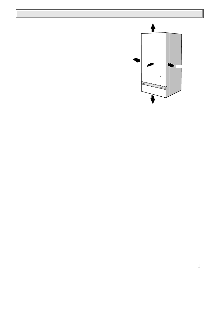
Diagram 1
3864
100mm
500mm
6mm
6mm
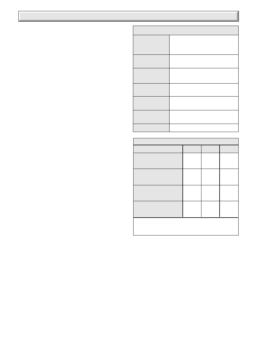
65mm
Data Label
The serial number and GC number of the boiler can be found on
the Data Label, see diagram 2.
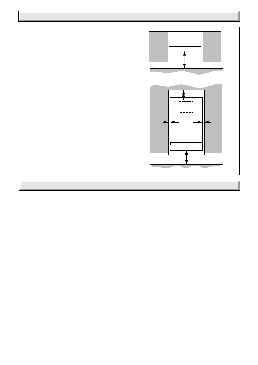
Boiler Clearances
If fixtures are positioned close to the boiler space must be left as
shown in diagram 1. Enough space must also be left in front of
the boiler to allow for servicing.
Boilers Installed in a Compartment or
Cupboard
If the boiler is installed in a compartment or cupboard do not
obstruct any ventilation openings.
Do not use the compartment or cupboard for storage.
Boiler Electrical Supply
WARNING. This boiler must be earthed.
The boiler must only be connected to a 230V~50Hz supply
protected by a 3A fuse.
All wiring must be in accordance with the current issue of
BS7671.
Wiring to the boiler must be PVC insulated type to the current
issue of BS6500 Table 16, not less than 0.75mm
2
(24/0.20mm).
The colours of 3 core flexible cable are:-
Brown - live, Blue - neutral, Green and yellow - earth.
As the markings on your plug may not correspond with these
colours, continue as follows:-
The wire coloured blue must be connected to the terminal
marked “N” or “Black”.
The wire coloured brown must be connected to the terminal
marked “L” or “Red”.
The wire coloured green and yellow must be connected to the
terminal marked “E”, “Earth”, “Green” or the earth symbol
.
4
221791B
Instructions for Use
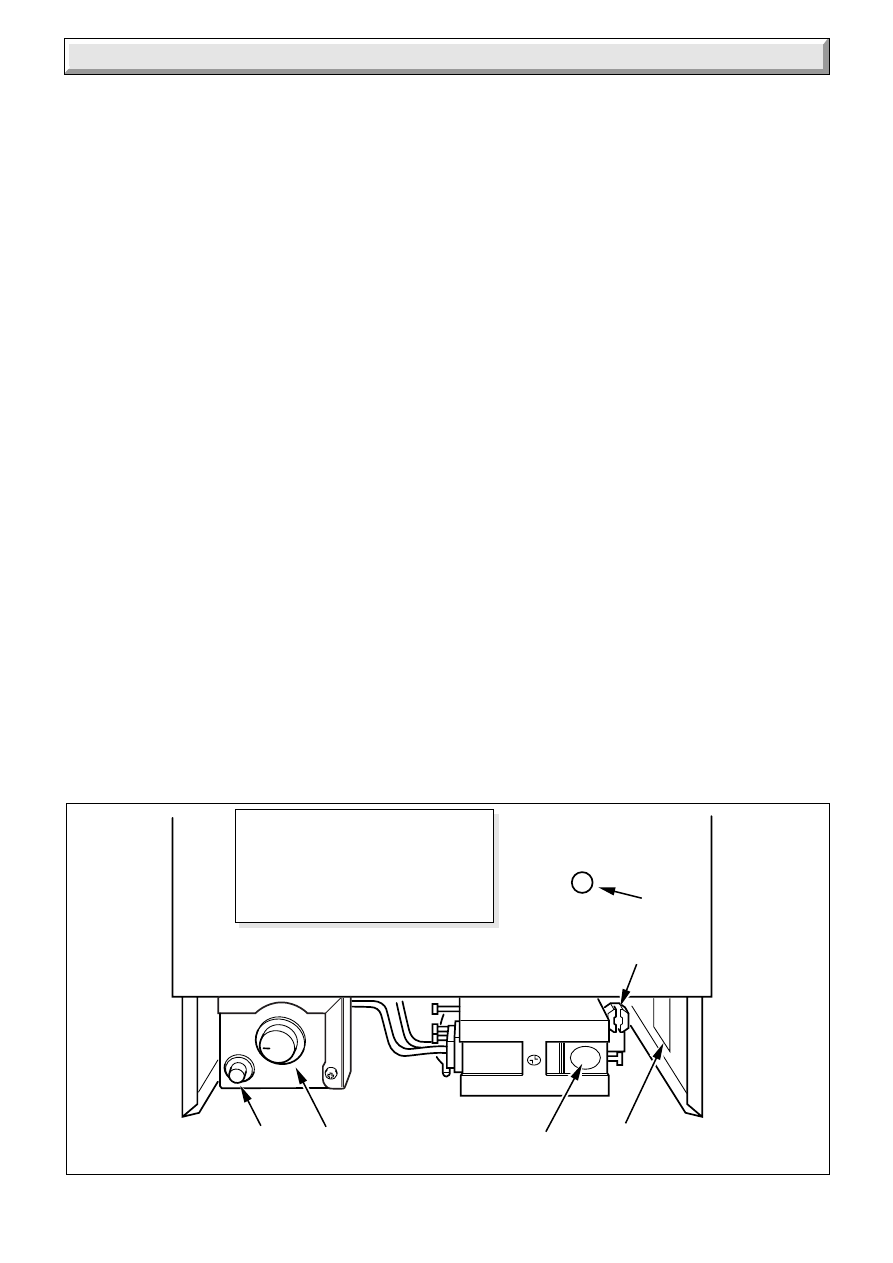
Diagram 2
A
PIEZO UNIT BUTTON
B
THERMOSTAT CONTROL KNOB
C
GAS SERVICE COCK
(shown in off position)
D
CONTROL BUTTON (GAS)
E
VIEWING WINDOW
3865
DATA LABEL
D
A
B
E
C
To Light The Boiler
WARNING. If the pilot flame goes out, either intentionally or by
accident, no attempt should be made to relight it for at least
three minutes.
Identify the controls by reference to diagram 2.
Switch off the electrical supply to the boiler.
Turn the control thermostat knob “B” fully anti-clockwise to the
“O”, Off position.
Push in control button “D”, keep pressed in and at the same time
operate the piezo button “A” until the pilot lights, look through
viewing window “E”. After the pilot lights keep the control button
“D” pushed in for 20 seconds. If the pilot fails to stay alight a
safety device prevents immediate relighting.
Do not attempt to relight until the safety device has reset, that
is, for at least three minutes.
Switch on the electrical supply and check that all external
controls are calling for heat.
Turn the control thermostat knob “B” clockwise to any position
between “MIN” and “MAX” and the burner will light.
The maximum setting is about 82
o
C (180
o
F).
The above sequence must be repeated every time that the
burner has to be relit.
To Turn the Boiler Off
For short periods, turn the control thermostat knob “B” fully anti-
clockwise to “O” Off. To relight, turn control thermostat knob
clockwise to any position between “MIN” and “MAX”.
For longer periods, turn the control thermostat knob “B” fully
anti-clockwise to “O” Off and slide multi-functional control
button “D” to the left, it will automatically reset. Switch off the
electrical supply to the boiler.
To relight, follow the full lighting sequence given above.
5
221791B
1 General Data
Important Notice
This boiler is for use only on G20 gas.
All dimensions are given in millimetres (except as noted).
This boiler can be used only on an open vented system, with
either gravity or pumped domestic hot water connections to the
indirect cylinder.
Wherever possible, all materials, appliances and components
used shall comply with the requirements of applicable British
Standards.
Where no British Standard exists, materials and equipment
should be fit for their purpose and of suitable quality and
workmanship.
Sheet Metal Parts
WARNING. When installing or servicing this boiler care should
be taken when handling sheet metal parts, to avoid any possibility
of personal injury.
1.1 Statutory Requirements
The installation of the boiler must be carried out by a competent
person in accordance with the relevant requirements of the
current issue of:-
Manufacturer’s instructions, supplied.
The Gas Safety (Installation and Use) Regulations, The
Building Regulations, The Building Standards (Scotland)
Regulations (applicable in Scotland), Local Water Company
Bye-laws, The Health and Safety at Work Act, Control of
Substances Hazardous to Health, The Electricity at Work
Regulations and any local regulations which may apply.
Detailed recommendations are contained in the current issue of
the following British Standards and Codes of Practice:-
BS6798, BS5440 Part 1 and 2, BS5546 Part 1, BS5449, BS6891,
BS6700, BS7593, BS7478, BS7671.
Manufacturer’s instructions must not be taken as overriding
statutory requirements.
1.2 Data
See Table 1
The Seasonal Efficiency Domestic Boilers UK (SEDBUK)
is 75.6%.
The value is used in the UK Government’s Standard Assessment
Procedure (SAP) for energy rating of dwellings. The test data
from which it has been calculated have been certified by B.S.I.
1.3 Range Rating
This boiler is range rated and may be adjusted to suit individual
system requirements.
Table 2 gives the ratings and settings.
1.4 B.S.I. Certification
This boiler is certificated to the current issue of British Standard
6332 Part 1, invoking the current issue of BS5258 Part 1 for
performance and safety. It is, therefore, important that no
alteration is made to this boiler without permission, in writing,
from Hepworth Heating Ltd.
Any alteration that is not approved by Hepworth Heating Ltd.,
could invalidate the B.S.I. Certification of the boiler, warranty
and could also infringe the current issue of the Statutory
Requirements.
MODELS
60BF
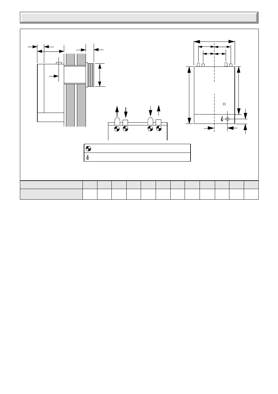
Diagram 1.1
OVERALL DIMENSIONS (given in millmetres)
22mm COPPER PIPE
GAS CONNECTION RC
1
/
2
(
1
/
2
in. BSPT.)
A
B
C
D
M
SIDE ELEVATION
FRONT ELEVATION
FLOW GRAVITY
RETURN PUMPED
GRAVITY RETURN
PUMPED FLOW
E
CL
L
P
R
F
S
S
N
N
75
297
156 398
700 360
574
35
94
131
60
146
A
B
C
D
E
F
L
M
N
P
R
S
6
221791B
1 General Data
1.5 Gas Supply
The gas installation shall be in accordance with the current
issue of BS6891.
The supply from the governed meter must be of adequate size
to provide a steady inlet working pressure of 20mbar (8in wg) at
the boiler.
On completion test the gas installation for soundness using the
pressure drop method and suitable leak detection fluid, purge
in accordance with the above standard.
1.6 Electrical Supply
WARNING. This boiler must be earthed.
All system components shall be of an approved type and shall
comply with and be connected in accordance with the current
issue of BS7671 and any applicable local regulations.
Connection of the boiler and system controls to the mains
supply must be through a common isolator and must be fused
3A, maximum. This method of connection must be by a fused
double pole isolating switch, with a minimum contact separation
of 3mm on both poles. The switch should be readily accessible
and preferably adjacent to the appliance. It should supply the
appliance only and be easily identifiable as so doing.
Alternatively, an unswitched shuttered socket outlet and 3A
fused 3 pin plug both to the current issue of BS1363 may be
used, provided that they are not used in a room containing a
bath or shower.
Wiring to the boiler must be PVC insulated type to the current
issue of BS6500 Table 16, not less than 0.75mm
2
(24/0.20mm).
1.7 Contents of Packaging
There are two packs, one contains the boiler, refer to Section 4.1
for contents.
The other pack contains the balanced flue terminal assembly,
wall duct and flue hood assembly.
Refer to Section 2.3 to check that the flue terminal assembly
supplied is suitable.
1.8 Water System
This boiler shall only be used on an unrestricted open vented
system with the water supply taken from a feed and expansion
cistern having a head of 27m (90ft) maximum.
This boiler must not be connected to a sealed water system.
1.9 Drain
System
A draining tap must be provided at the lowest points of the
system which will allow the entire system, boiler and hot water
cylinder to be drained.
Draining taps should be to the current issue of BS2879.
Boiler
A draining point is fitted at the bottom right hand side of the heat
exchanger. Cover controls to avoid water damage. If required
remove the combustion chamber front cover to improve access.
RANGE RATING
NOMINAL
kW
HEAT
INPUT(GROSS)
Btu/h
NOMINAL
kW
HEAT
OUTPUT
Btu/h
BURNER
m bar
SETTING
PRESSURE
in.w.g
APPROX
m
3
/h
GAS
RATE
ft
3
/h
TABLE 2.
18.55
20.27
21.98
63,300
69,150
75,000
14.65
16.12
17.58
50,000
55,000
60,000
8.6
10.3
12.6
3.5
4.1
5.1
1.78
1.95
2.12
63
69
75
min
medium
max
3.35Litre
(0.74gal)
50.7kg
(112lb)
38.2kg
(84lb)
DATA TABLE 1.
DATA LABEL
Bottom right hand side of case
ELECTRICITY
SUPPLY
WATER
CONNECTION
GAS
CONNECTION
WATER
CONTENT
LIFT WEIGHT
( I n c l u d i n g
Terminal)
TOTAL DRY
4 x 22mm copper pipes from
top of case
Rc
1
/
2
in.
230V~50Hz, fused 3A.
WEIGHT
BURNER INJECTOR MARKING: 205701
PILOT INJECTOR MARKING: 7215
1.10 Safety Valve
A safety valve need not be fitted to an open vented system.
1.11 Location
This boiler is not suitable for outdoor installation.
This boiler may be installed in any room, although particular
attention is drawn to the requirements of the current issue of
BS7671 with respect to the installation of a boiler in a room
containing a bath or shower. Any electrical switch or boiler
control utilising mains electricity should be placed so that it
cannot be touched by a person using the bath or shower.
The electrical provisions of the Building Standards (Scotland)
Regulations apply to such installations in Scotland.
The boiler must be mounted on a flat wall which is sufficiently
robust to take its total weight.
7
221791B
1 General Data
500mm
Additional clearance may be
required for installation
65mm
100mm
6mm
6mm
FRONT VIEW
TOP VIEW
3792
Diagram 1.2
Note: Detailed recommendations for flues are given in the
current issue of BS5440 Part 1.
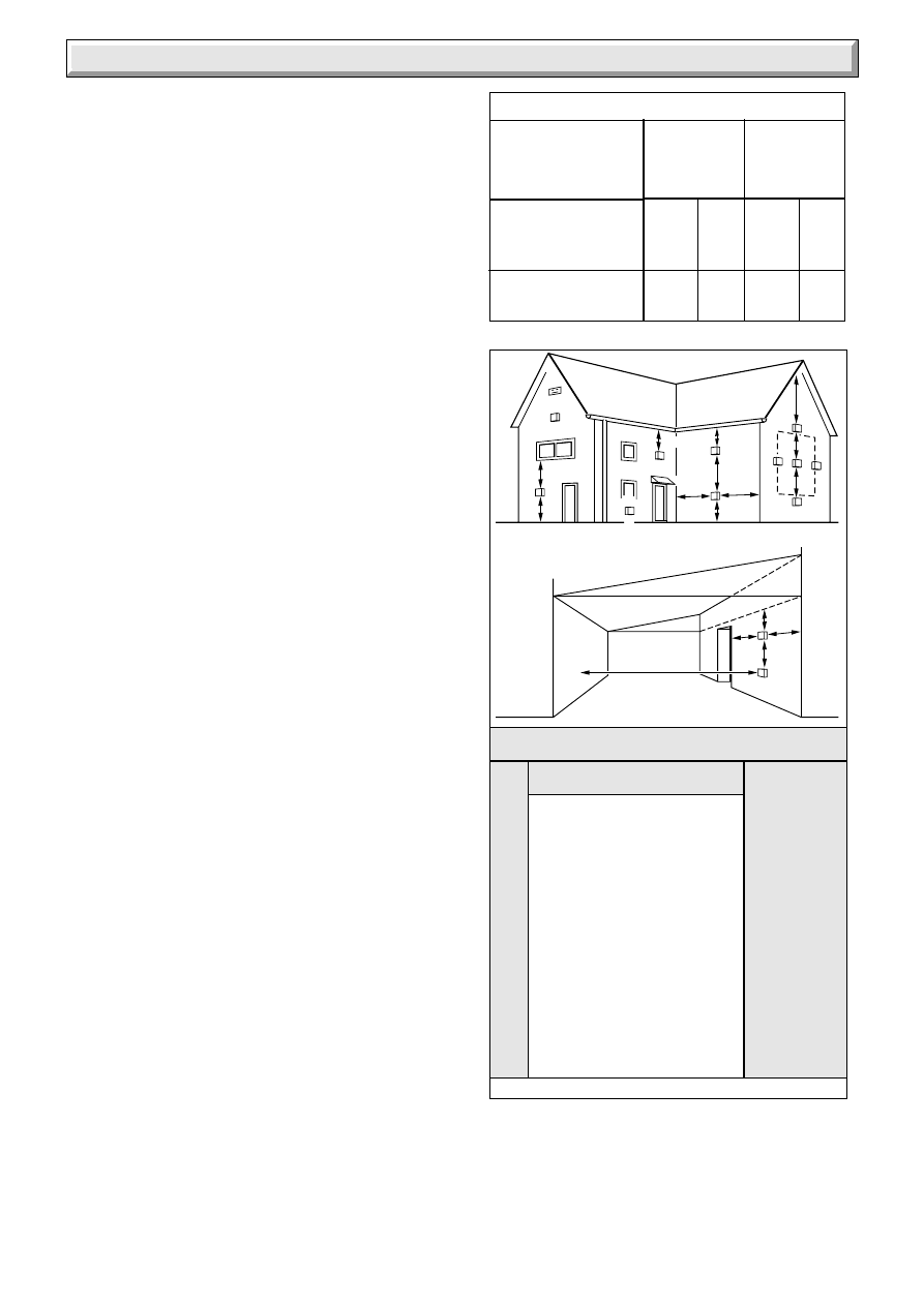
2.1 Terminal Position
The minimum acceptable siting dimensions for the terminal
from obstructions, other terminals and ventilation openings are
shown in diagram 2.1.
The terminal must be exposed to the external air, the position
allowing free passage of air across it at all times.
Car ports or similar extensions of a roof only, or a roof and one
wall, require special consideration with respect to any openings,
doors, vents or windows under the roof. Care is required to
protect the roof if it is made of plastic sheeting. If the car port
consists of a roof and two or more walls, seek advice from the
local gas company before installing the boiler.
If the terminal is fitted within 600mm below plastic guttering or
painted soffit an aluminium shield 1500mm long should be fitted
immediately beneath the guttering or eaves. If the terminal is
fitted within 450mm below painted eaves or a painted gutter, an
aluminium shield 750mm long should be fitted immediately
beneath the guttering or eaves.
2.2 Terminal Guard
A terminal guard is required if persons could come into contact
with the terminal or the terminal could be subject to damage.
If a terminal guard is required, it must be positioned to provide
a minimum of 50mm clearance from any part of the terminal and
be central over the terminal.
A suitable guard, reference Type “F”, can be bought from:-
Tower Flue Components Ltd
Morley Road
Tonbridge
Kent. TN9 1RA
2.3 Wall Thickness
Check the thickness of the wall.
Flues available are:-
Standard Pack:-
60BF Part No.446002 for 280 to 410mm (11in to 16in)
Extension Pack:- Part No.424680 plus
Standard Pack as above for 410 to 625mm (16 to 25in)
Note: If the wall thickness is less than 280mm the wall duct and
flue ducts can be cut down, to a minimum length of 100mm.
2.4 Room Ventilation
The boiler is room sealed and does not require the room or
space containing it to have permanent air vents.
2 Flue and Ventilation
1.12 Boiler Clearances
Refer to diagram 1.2.
This boiler must be positioned so that at least the minimum
operational and servicing clearances are provided.
Additional clearances may be required for installation.
If fixtures are positioned next to the boiler they should be made
removable for access to pipework.
Sufficient clearance must be left in front of the boiler for
servicing.
1.13 Heating System Controls
The heating system should have installed: a programmer and
room thermostat controlling the boiler.
Thermostatic radiator valves may be installed in addition to the
room thermostat.
Note: For further information, see The Building Regulations
1991 - Conservation of fuel and power, 1995 edition - Appendix
G, table 4b.
8
221791B
2 Flue and Ventilation
2.5 Boilers in a Compartment
Where the installation of the boiler will be in an unusual position,
special requirements are needed, the current issue of BS6798
gives detailed guidance on these requirements.
A compartment used to enclose the boiler must be designed
and constructed specifically for this purpose. An existing
cupboard or compartment modified for the purpose may be
used. Details of essential requirements for cupboard or
compartment design are given in the current issue of BS6798.
The doorway opening should be of sufficient size to allow for
easy removal of the boiler.
Where the boiler is fitted in a cupboard or compartment,
permanent high and low level ventilation must be provided. The
minimum ventilation areas required are given in Table 3.
2.6 Timber Frame Building
If the boiler is to be installed in a timber frame building it should
be fitted in accordance with the Institute of Gas Engineers
document IGE/UP/7/1998. If in doubt seek advice from the local
gas undertaking or Hepworth Heating Ltd.
Diagram 2.1
A
DIRECTLY BELOW AN OPENABLE
WINDOW, AIR VENT, OR ANY OTHER
VENTILATION OPENING
300
B
BELOW GUTTER, DRIAN/SOIL PIPE
300
C
BELOW EAVES
300
D
BELOW A BALCONY OR CAR PORT
600
E
FROM VERTICAL DRAIN PIPES AND
SOIL PIPES
75
F
FROM INTERNAL OR EXTERNAL
CORNERS
250
G
ABOVE ADJACENT GROUND OR
BALCONY LEVEL
300
H
FROM A SURFACE FACING THE
TERMINAL
600
I
FACING TERMINALS
600
J
FROM OPENING (DOOR/WINDOW) IN
CAR PORT INTO DWELLING
1200
K
VERTICAL FROM A TERMINAL
1500
L
HORIZONTALLY FROM A TERMINAL
300
MINIMUM
POSITION
SPACING (mm)
MINIMUM SITING DIMENSIONS FORBALANCED FLUE
TERMINALS
3815A
Under Car Port etc.
H,I
J
D
F
K
A
A
F
G
E
A
G
G
B,C
B,C
F
F
K
K
K
C
L
L
G
G
FROM
OUTSIDE
COMPARTMENT AIR VENT TABLE
COMPARTMENT
VENTILATION
REQUIREMENTS
99cm
2
15in
2
99cm
2
15in
2
VENTILATION
FROM ROOM
OR SPACE
198cm
2
30in
2
198cm
2
30in
2
HIGH LEVEL
LOW LEVEL
VENT AREA
VENT AREA
9
221791B
3 Water Systems
The installation of the boiler must comply with the requirements
of the current issue of BS6798.
3.1 Frost Protection
If the position of the boiler is such that it may be vulnerable to
freezing it should be protected as specified in the current issue
of BS5422. It is recommended that a frost protection thermostat
be fitted.
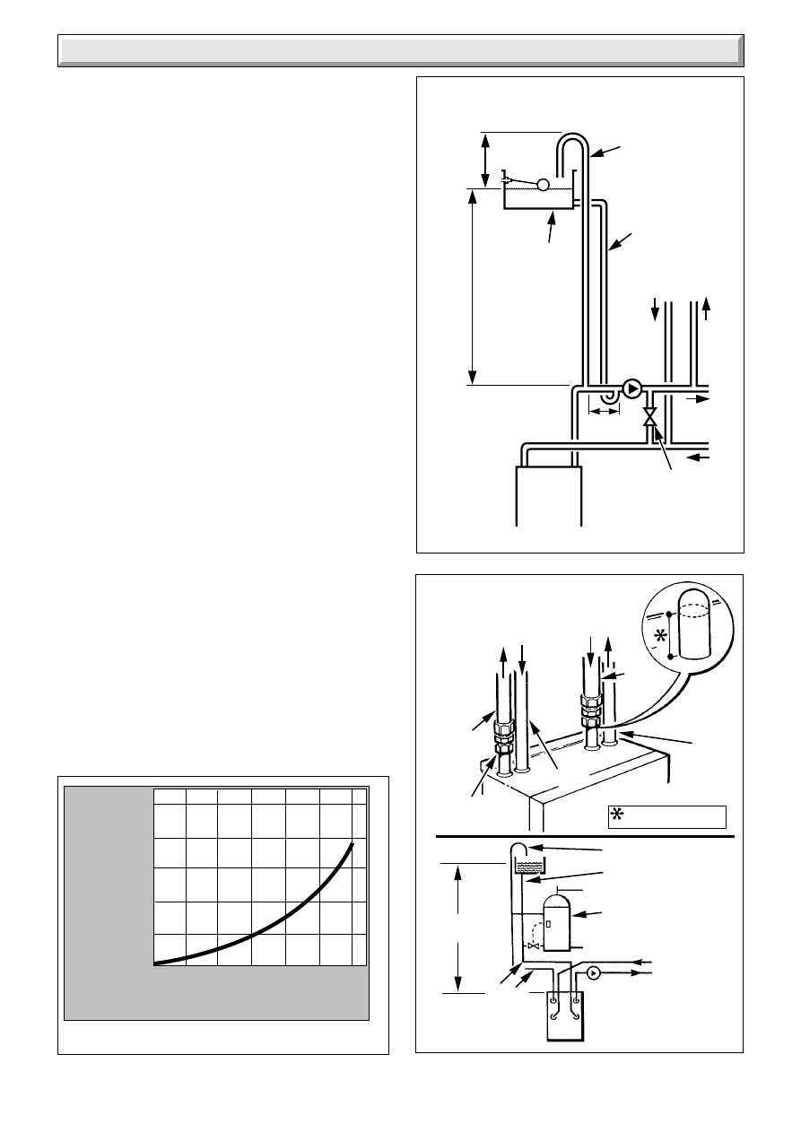
3.2 Pump
The pump, with integral valves, should be fitted in the heating
flow pipework from the boiler, it should be set to produce a
temperature difference of 11
o
C (20
o
F), between the flow and
return, with the control thermostat set at “MAX”, which is about
82
o
C (180
o
F).
The resistance through the boiler can be found from diagram 3.1.
High resistance microbore systems may require a higher duty
pump.
3.3 Bypass - Fully Pumped Water System
A bypass is usually unnecessary on systems using a 3 port
diverter valve since one port will remain in the open position at
all times. This allows satisfactory operation of the pump
overrun.
However if thermostatic radiator valves are fitted to all radiators
or two port valves are used a bypass is required.
The bypass connection must be at least 2 metres away from the
boiler.
The flow through the boiler must not be allowed to fall such that
there is a temperature difference greater than 20
o
C between the
flow and return.
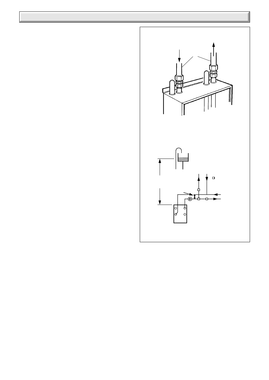
3.4 Water System
The cold feed must be 15mm minimum size.
It is important that the relative positions of the pump, cold feed
and open vent are as shown in diagram 3.2.
The unrestricted open vent from the boiler must rise continuously
to discharge over the feed and expansion cistern.
PRESSURE LOSS OF BOILER
4631
Diagram 3.1
Diagram 3.3
3794
Note:
When cutting leave
sufficient length for fittings
COMPRESSION
JOINT
22mm
PIPE
28mm
PIPE
FLOW (GRAVITY)
RETURN
FLOW
28mm
PIPE
22mm
PIPE
HEATING
SYSTEM
PUMP
VIEWED
FROM
FRONT
28mm
1m MIN.
27m MAX.
INDIRECT CYLINDER
(Shown with
recommended
thermostat and valve)
15mm COLD FEED
22mm VENT
REFER TO BS5546
RETURN (GRAVITY)
6455
FEED AND
EXPANSION
CISTERN
22mm VENT
(MIN.)
15mm (MINIMUM)
COLD FEED
OPEN VENTED FULLY PUMPED WATER SYSTEM
RECOMMENDED RELATIONSHIP BETWEEN
PUMP COLD FEED AND VENT
450mm
MIN.
HEIGHT
1150mm
MIN.
RETURN
FLOW
CYLINDER
PUMP
HEATING
150mm
MAX.
BOILER
IF REQUIRED
15mm (MINIMUM)
BY-PASS WITH
LOCKSHIELD VALVE
FLOW
RET.
There must always
be a cold water path
to the return
connection
of the boiler.
Diagram 3.2
Water pressure loss
(mm head of water)
Flow rate (litres/minute)
0
5
10
15
20
25
30
0
250
500
750
1000
10
221791B
3 Water Systems
3.5 Domestic Hot Water System
General. The domestic hot water service must be in accordance
with the current issue of BS5546, refer also to the current issue
of BS6700.
3.6 Indirect Cylinder
For all systems supplying domestic hot water the cylinder must
be indirect. It is recommended that the indirect cylinder be fitted
with some form of temperature control.
3.7 Gravity Domestic Hot Water with Pumped
Heating
Important: If domestic hot water is to be provided by a gravity
circulation to the indirect cylinder the blanked off connections
must be opened and used, using 22x28mm connections, see
diagram 3.3.
3.8 Fully Pumped Heating and Domestic Hot
Water
The connections for this type of system MUST be as shown in
diagram 3.2 and 3.4.
3.9 Inhibitor
Attention is drawn to the current issue of BS5449 and BS7593
on the use of inhibitors in central heating systems.
If an inhibitor is to be used, contact a manufacturer or
Hepworth Heating Ltd., for their recommendations as to the
best product to use.
When installing in an existing system take special care to drain
the entire system, including radiators, then thoroughly cleaning
out before installing the boiler whether or not adding an inhibitor.
1metre Min.
27 metres
Max.
22mm VENT & 15mm COLD FEED
TO BE FITTED IN ACCORDANCE
WITH BS 5449
INDIRECT
CYLINDER
ALTERNATIVE
SYSTEM
CONTROL
VALVES
HEATING
SYSTEM
PUMP
FULLY PUMPED CIRCULATION
SYSTEM (DIAGRAMMATIC)
IF REQUIRED
BYPASS 15mm
MIN WITH
LOCKSHIELD
VALVE
Diagram 3.4
22mm
PIPE
RETURN
FLOW
4107
6461

11
221791B
4 Flue and Appliance Preparation
4.1 Unpacking
Open the carton containing the boiler, remove the end fitting
which contains, wall mounting bracket, heat exchanger baffles
and loose items pack. Check the items supplied against the
contents list on the flap and diagram 4.1.
With the boiler still in the bottom tray, slide the controls cover
upward and remove it as shown in diagram 4.2. Remove the
case by undoing the wing nuts and lifting the case off, see
diagram 4.2.
Remove the packing piece from inside the case.
Place on one side until required.
Place the boiler on one side until required.
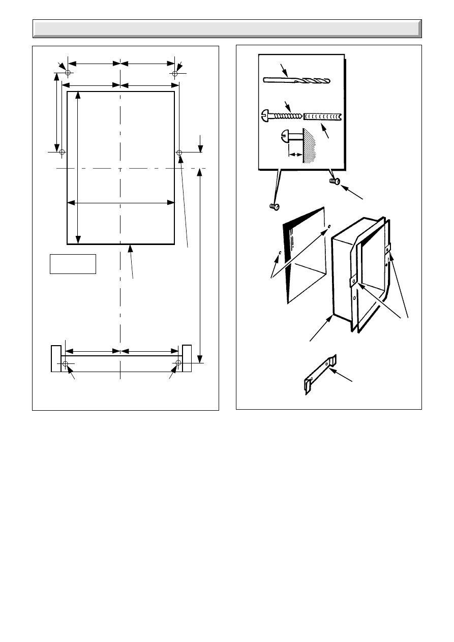
4.2 Positioning
Select the boiler position. Take due account of the position of
the flue terminal, see diagram 2.1.
Use the template, making sure it is square and mark out the
position of the flue opening, see diagram 4.3.
Cut a hole through the wall as neatly as possible.
Note. If the hole is oversize or of an irregular shape it must be
faced off to the hole dimensions shown.
Use template, again, making sure that it is positioned both
square and central to the flue hole, marking the fixing points at
the top, bottom and clearance holes for wall duct.
Remove the wall template after marking, then check marked
positions against diagram 4.3.
Drill holes to accept the plugs and screws supplied in the loose
items pack.
Secure the bottom bracket to the wall, using the plugs and
screws.
Make sure the bracket is level.
Drill a 7mm clearance hole to a depth of 10mm.
Fit plugs into top fixing holes and fit screws, leaving about 5mm
proud.
Take the balanced flue assembly and wall duct from its carton,
place the balanced flue assembly on one side until it is required.
Note. If fitting a short flue it will be necessary to cut wall duct,
see Table 4.
Position the wall duct, see diagram 4.4.
Diagram 4.1
3795
WALL TEMPLATE
BALANCED
FLUE TERMINAL
PACK
(Supplied separately)
WALL
MOUNTING
BRACKET
INSTALLATION
& SERVICING
LITERATURE
CONTENTS LIST
Printed on carton flap
BOILER
LOOSE ITEMS
PACK
HEAT
EXCHANGE
BAFFLES
CARTON
Diagram 4.2
3796
SECURING WING NUTS (2)
CARTON
CASE
CONTROLS COVER
12
221791B
4 Flue and Appliance Preparation
Diagram 4.3
Diagram 4.4
3797
*
*
CL
CL
168
122
122
112
112
FIXING
POINTS
FIXING
POINTS
FLUE
HOLE
CLEARANCE
HOLE (2)
420
35
119
119
*
*
*
220
325
3798
5mm
wall
plug
No. 12 X 2" long
woodscrew
7mm dia. drill
WALL
DUCT
CLEARANCE
HOLE
SECURING
SCREWS (2)
SECURING
CLIPS
MOUNTING
BRACKET
13
221791B
5 Boiler Installation
5.1 Mounting the Boiler
Remove the boiler from the carton tray.
If necessary, for a gravity domestic hot water system cut the
pipes as shown in diagram 3.3.
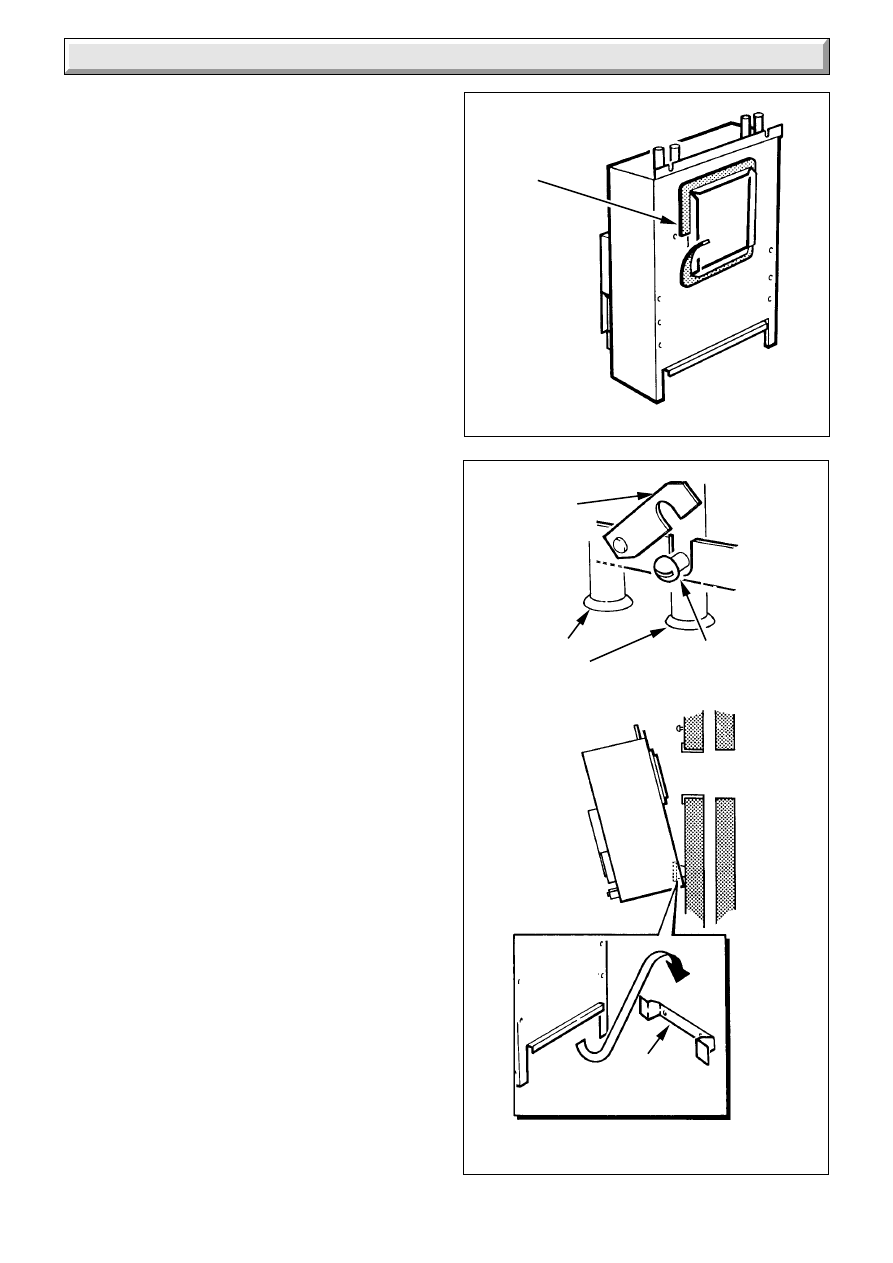
Stand boiler upright on the packaging, to protect the paintwork.
Stick the foam seal around the boiler flange, at the back, making
sure it is a tight fit, around the corners, see diagram 5.1.
Fit suitable fittings to the pipework.
Now make sure that the top, swing brackets are UPRIGHT, see
diagram 5.2.
Lift the boiler into position, hooking over the bottom wall bracket.
Swing the brackets over the two screws at the top and secure,
see diagram 5.2.
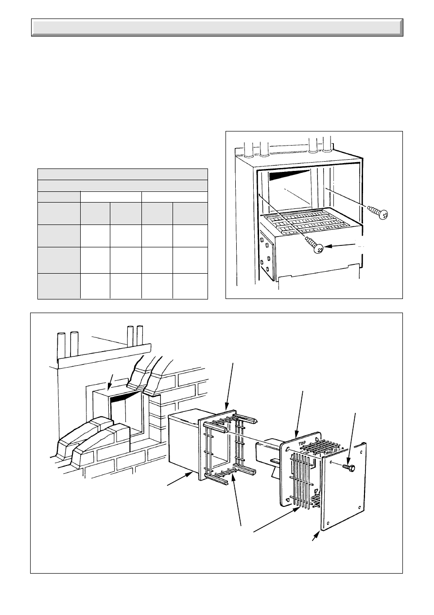
Secure the boiler to the flange on the wall duct, see diagram 5.3.
Note. For a short flue it will be necessary to cut the balanced flue
assembly, see Table 4.
Take the balanced flue assembly from its carton and remove the
four screws to release the outer baffle, wire guards and inner
baffle flue duct assembly, from the air duct assembly, see
diagram 5.4.
From the outside place the air duct assembly into the hole in the
wall, fit it around the wall duct, slide in until the wall plate touches
the wall surface. Make sure the air duct wire guards are in
position.
Seal the joint in the air ducts with the yellow tape provided. Tape
four pieces into the four inside corners, followed by four along
the joints overlapping the corner pieces, to make a good seal,
see diagram 5.4A. Allow a minimum of 20mm (
3
/
4
in) overlap of
the ductings.
Take the flue hood assembly, remove the access door, secure
the assembly to the boiler, with the screws provided in the loose
items pack, see diagram 5.5.
Place the inner baffle and flue duct assembly into the hole in the
wall outside, fit it around the flue duct on the boiler and slide it
in until it touches the air duct assembly wire guards.
Seal the flue duct joint on the inside with the heat resistant semi-
transparent tape provided, see diagram 5.4A.
Cement around the wall plate.
To complete the flue terminal assembly, refit wire guards, outer
baffle and secure with screws.
Fit the boiler flue baffles, see diagram 5.6.
Refit the flue access door.
Diagram 5.1
Diagram 5.2
3799
FOAM
SEAL
3800
SWING
BRACKET
PIPES
REMOVED
FOR CLARITY
SECURING
SCREW (2)
MOUNTING
BRACKET
MOUNTING THE BOILER
14
221791B
5 Boiler Installation
Diagram 5.4
TABLE 4.
SHORT FLUE 100-280 CUTTING LENGTHS
100-150
150-200
200-280
WALL
THICKNESS
AIR DUCT
FLUE DUCT
0
130
130
0
20
190
190
20
70
190
190
70
Diagram 5.3
Flue
Duct
Air
Duct
Wall
Duct
3801
3802
SECURING
SCREW (2)
WALL DUCT
WIRE
GUARDS
OUTER
BAFFLE
WALL
PLATE
SCREW (4)
INNER BAFFLE/
FLUE DUCT
ASSEMBLY
AIR DUCT
ASSEMBLY
Inner Baffle
Flue Duct
5.2 Water Circulation System
Complete the water connections to the boiler.
Fill, vent and cold flush the system as recommended in the
current issue of BS6798.
Check for any water leaks and put right.
5.3 Gas Connection
Make the gas connection to the Rc
1
/
2
in gas service cock.
Check for leaks using a suitable leak detection fluid.
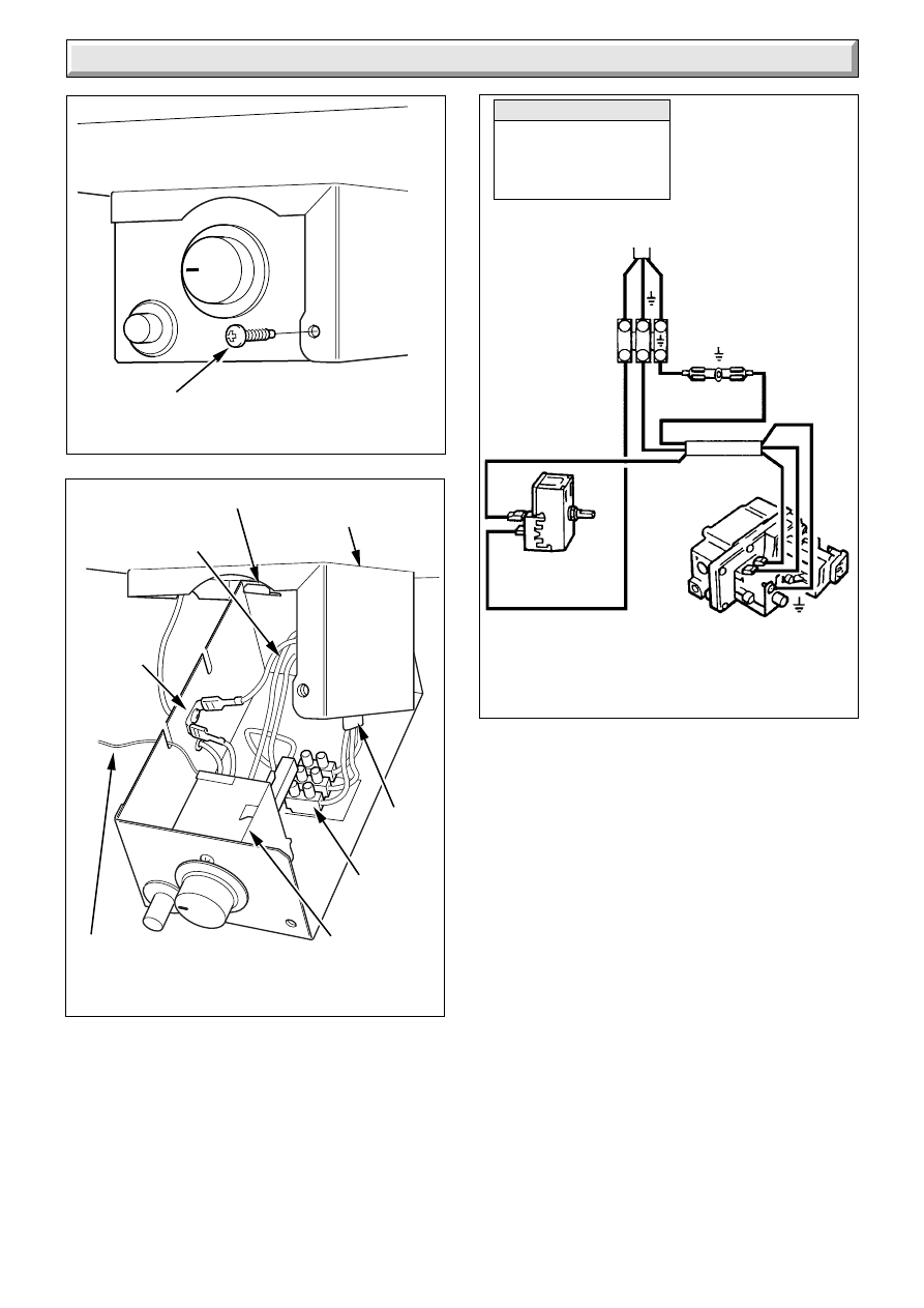
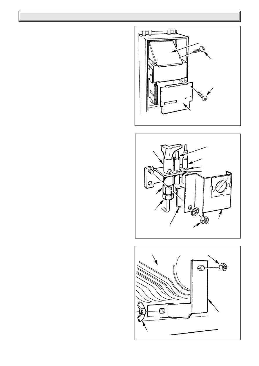
5.4 Control Box
Remove the electrical control box securing screw, see diagram
5.7. Pull the control box down at the front and support on the
hook at the rear of the control box cover, see diagram 5.8.
15
221791B
5 Boiler Installation
Diagram 5.4A
Diagram 5.5
3803
AIR
DUCTS
YELLOW
SEALING
TAPE
FLUE HOOD
ASSEMBLY
SEMI-TRANSPARENT
SEALING TAPE
3804
FLUE
DUCT
FLUE DUCT/
FLUE HOOD
5mm
SECURING
SCREWS (4)
SECURING
SCREW (2)
FLUEWAY
ACCESS
DOOR
5.5 Electrical Connection
Thread the mains cable through the cable clamp in the rear of
the box and connect to the terminal strip, see diagram 5.8 and
5.9.
Standard colours are, brown - live (L), blue - neutral (N) and
green and yellow - earth (E).
The mains cable outer insulation must not be cut back external
to the cable clamp.
Make sure the cable is suitably secured.
When making connections, make sure that the earth conductor
is made of a greater length than the current carrying conductors,
so that if the cable is strained the earth conductor would be the
last to become disconnected.
5.6 Testing
Checks to ensure electrical safety must be carried out by a
competent person.
After installation of the system, preliminary electrical system
checks as below should be carried out:
1. Test insulation resistance to earth.
2. Test earth continuity and short circuit of all cables.
3. Test the polarity of the mains.
Refit the control box.
The installer is requested to advise and give guidance to the
user of the controls scheme used with the boiler.
Diagram 5.6
3805
BAFFLE (4)
16
221791B
5 Boiler Installation
Diagram 5.7
8040
SECURING
SCREW
Diagram 5.8
Diagram 5.9
MULTI-
FUNCTIONAL
CONTROL CABLE
EARTH
TERMINAL
CONTROL
THERMOSTAT
THERMOSTAT
CAPILLARY
MAINS
CABLE
8051
8038
MULTI-FUNCTIONAL
CONTROL
CONTROL
THERMOSTAT
KEY
br
BROWN
g/y GREEN/YELLOW
bl
BLUE
bk
BLACK
230V~50Hz
MAINS SUPPLY
FUSED AT 3A
N
L
L
N
g/y
g/y
g/y
bk
br
bl
br
bk
bl
EARTH
HOOK
CONTROL
BOX COVER
17
221791B
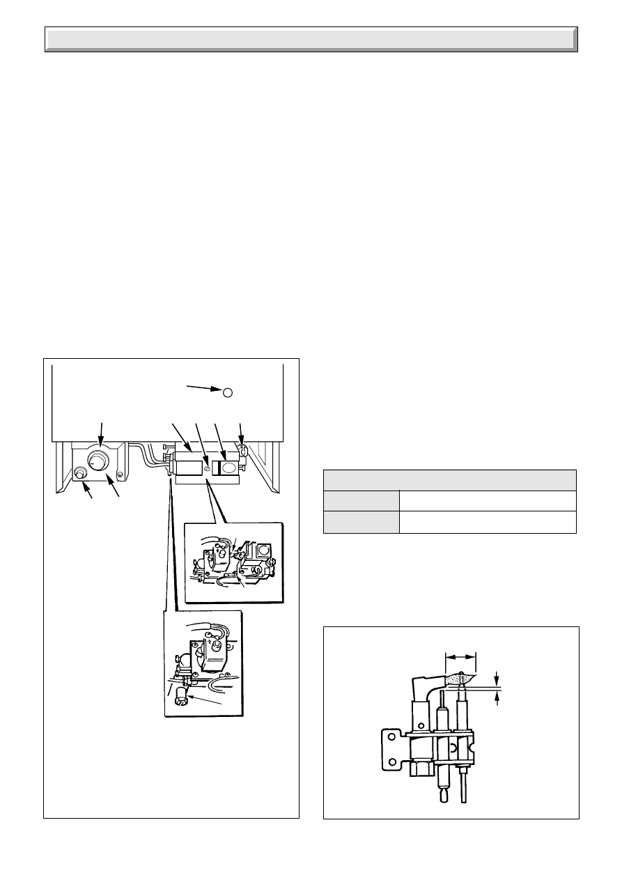
6 Commissioning
8042
2 to 4mm
12 to 14mm
F
A
ELECTRICAL
CONTROL BOX
B
THERMOSTAT
CONTROL KNOB
C
GAS SERVICE
COCK (SHOWN IN
OFF POSITION)
D
MULTI-FUNCTIONAL
CONTROL
E
PRESSURE TEST
NIPPLE
F
GAS BURNER
PRESSURE SCREW
G
PIEZO UNIT BUTTON
H
WINDOW PILOT
K
CONTROL BUTTON (GAS)
M
COVER SECURING SCREW
N
PILOT BURNER PRESSURE
SCREW
B
A
D
M
K
C
N
G
H
3810
Diagram 6.2
Please ensure the "Benchmark" logbook is completed and left
with the user.
6.1
Make sure that the system has been thoroughly flushed out with
cold water without the pump in place.
Refit the pump, fill the system with water, making sure that all
the air is properly vented from the system and pump.
Before operating the boiler check that all external controls are
calling for heat.
6.2 Initial Lighting and Testing
CAUTION. This work must be carried out by a competent
person, in accordance with the current issue of BS6798.
Make sure that all naked lights and cigarettes are out.
Identify the controls by reference to diagram 6.1.
Turn the control thermostat knob “B” to “O” the Off position.
Remove gas pressure test point screw “E” and fit a suitable
pressure gauge.
Turn the electrical supply on and check that all remote controls
are calling for heat. Check that the pump is circulating water
through the system.
Turn on the main gas supply and purge in accordance with the
current issue of BS6891.
Turn boiler gas service cock “C” “On”.
Push in control button “K”, keep pressed in and at the same time
operate the piezo unit button “G” until the pilot burner lights.
After the pilot burner lights keep the button “K” pushed in for 20
seconds. If the pilot fails to stay alight a safety device in the
multi-functional control prevents immediate relighting.
Do not attempt to relight until the safety device has reset, that
is, after a minimum of three minutes.
Make sure that the pilot is alight and stable, view through
window “H”.
Check the length of the pilot flame, it should envelop the
thermocouple tip as shown in diagram 6.2. The pilot rate can be
adjusted, if necessary, by turning the pilot burner adjustment
screw “N”, having first removed the multi-functional control
cover by releasing the screw, see diagram 6.1. Check the pilot
supply connection for gas soundness, using a suitable leak
detection fluid.
Fit the case by hooking it under at the top and securing with the
wing nuts previously removed, see diagram 6.3.
Set the control thermostat knob “B” between “MIN” and “MAX”
- “MAX” is about 82
o
C (180
o
F) and check that the burner lights
smoothly. Check all the gas connections for soundness with a
suitable leak detection fluid.
To set the burner pressure, operate the boiler for ten minutes,
adjust the gas rate screw “F”, see diagram 6.1 until the required
pressure is obtained, see relevant Table 2 for setting pressures.
Should any doubt exist about the gas rate, check it using the gas
meter test dial and a stop watch, at least ten minutes after the
burner has lit, make sure that all other gas burning appliances
and pilot lights are off.
These figures are offered as a guide only.
Stick the self adhesive arrow, from the loose items pack, in the
appropriate place of the “MIN” “MED” and “MAX” column of the
Data Label.
Remove the pressure gauge and refit the test point screw,
making sure a gas tight seal is made.
m
3
/h
2.04
ft
3
/h
72.0
Gas Rates After 10 Minutes
8046
Diagram 6.1
E
18
221791B
6 Commissioning
Diagram 6.3
3811
ENSURE
CASE ENGAGEMENT
CASE
CONTROLS
COVER
6.3 Testing
To check the operation of the flame failure device, turn the gas
cock “Off”.
The multi-functional control should shut down within 60 seconds,
indicated by a “click” from the multi-functional control.
Turn gas cock “On” and relight the burner.
Allow the system to reach maximum working temperature and
examine for water leaks.
There should be no undue noise in the system and no pumping
over of water or entry of air at the open vent above the feed and
expansion cistern.
The boiler should then be turned off and the system drained off
as rapidly as possible, whilst still hot.
6.4 Adjustment - Fully Pumped Water System
When commissioning the system the boiler should first be fired
with the bypass fully closed on full service, that is, central
heating and domestic hot water. The system should then be
balanced, adjusting the pump and lockshield valve as necessary.
Having achieved a satisfactory condition operate the boiler with
the bypass fully closed on minimum load, normally this will be
central heating only with one radiator in the main living area
operating. The bypass valve should be gradually opened to
achieve the design temperature difference between the flow
and return.
UNDER NO CIRCUMSTANCES SHOULD THIS VALVE BE
LEFT IN THE FULLY CLOSED POSITION.
Note. Operate the boiler on full service and check the balancing,
making further adjustments as necessary.
Do not attempt to adjust the control thermostat calibration.
6.5 Thermostatic Radiator Valves
If thermostatic radiator valves are fitted care must be taken to
make sure that an adequate flow rate through the boiler when
they close, refer to the current issue of BS7478 for guidance.
6.6 Completion
Fit the controls cover by hooking into the sliders and pushing it
back as far as it will go, see diagram 6.3.
6.7 Protection Against Freezing
If the boiler is to be out of use for a period of time during severe
weather conditions we recommend that the whole of the system
including the boiler, be drained off to avoid the risk of freezing
up.
7 Instructions to the User
Instruct and demonstrate the safe and efficient operation of the
boiler, heating system and domestic hot water system.
Advise the user, that to ensure the continued efficient and safe
operation of the boiler it is recommended that it is checked and
serviced at regular intervals. The frequency of servicing will
depend upon the particular installation and usage, but in general
once a year, preferably at the end of the heating season should
be enough.
Draw attention, if applicable, to the current issue of the Gas
Safety (Installation and Use) Regulations, Section 35, which
imposes a duty of care on all persons who let out any property
containing a gas appliance.
It is the Law that servicing is carried out by a competent person.
Advise the user of the precautions necessary to prevent damage
to the system and building in the event of the heating system
being out of use during frost and freezing conditions.
Reminder, leave these instructions and the ‘Benchmark’ logbook
with the user.
Instructions to the User
19
221791B
8 Servicing
Notes: To ensure the continued efficient and safe operation of
the boiler it is recommended that it is checked and serviced as
necessary at regular intervals. The frequency of servicing will
depend upon the particular installation conditions and usage,
but in general once a year, preferably at the end of the heating
season should be enough.
It is the Law that any servicing is carried out by a competent
person.
Before servicing turn off the gas and isolate the electrical supply
to the boiler.
After completing a service always test for gas soundness and
carry out functional check on controls.
Unless stated otherwise all parts are replaced in the reverse
order to removal.
8.1 Access
Refer to diagram 6.3 and slide the controls cover forwards and
off.
Undo the wing nuts and remove the case.
When refitting the case check the condition of the case seal, if
it needs replacing refer to Section 10.12.
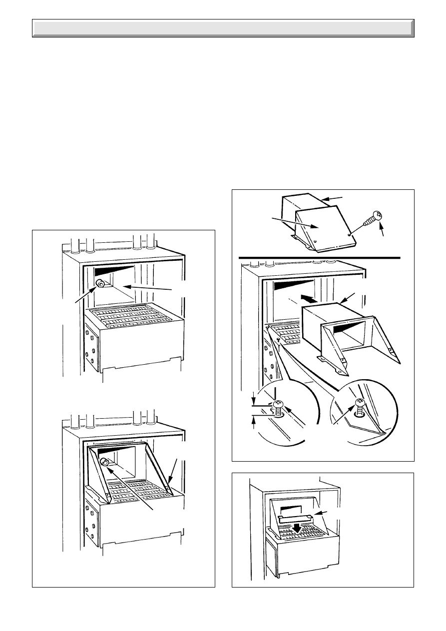
8.2 Main Burner
Remove the flueway access door by removing the screws, see
diagram 8.1.
Remove the combustion chamber front, see diagram 8.1.
Disconnect the pilot pipe union connector and ignition lead, see
diagram 8.2.
Separate the pilot assembly from the main burner, by removing
the pilot shield securing nut, shakeproof washer and move to
the right. Remove the burner securing nut and wing nut from the
burner support bracket, remove the burner support bracket, see
diagram 8.3.
To remove the main burner from the main injector at the rear,
raise the burner up and forwards, easing the pilot pipe to the
side, to clear, take care not to damage the combustion chamber
insulation or the pilot burner assembly.
Use a vacuum cleaner or suitable stiff brush to clean the burner
thoroughly, making sure that all the burner ports are clear and
unobstructed.
Do not use a brush with metallic bristles.
Diagram 8.1
3812
FLUEWAY
ACCESS
DOOR
SECURING
SCREW (2)
SECURING
SCREW (4)
COMBUSTION
CHAMBER
FRONT
Diagram 8.2
3813
SECURING
NUT
PILOT
INJECTOR
PILOT
UNION
CONNECTOR
PILOT
BURNER
SPARK
ELECTRODE
THERMOCOUPLE
SPRING
CLIP
PILOT
SHIELD
IGNITION
LEAD
3814
BURNER
SUPPORT
BRACKET
WING NUT
BURNER
SECURING
NUT
Diagram 8.3
20
221791B
8 Servicing
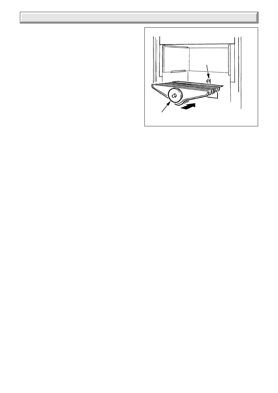
8.3 Cleaning Heat Exchanger
Place a sheet of paper in the base of the combustion chamber.
Remove the baffles from the heat exchanger, note, when
replacing the 60BF is marked “TOP”, see diagram 5.6.
Clean the heat exchanger, paying particular regard to the gaps
between the fins, with a suitable stiff brush.
Do not use a brush with metallic bristles.
Remove the paper together with any debris.
8.4 Main Injector
The main injector can be inspected and cleaned as necessary.
If removing for cleaning do not use a wire or sharp instrument
on the hole.
Use a little suitable sealant on the external thread when refitting
to make sure a gas tight seal is made.
8.5 Electrode, Pilot Burner and Pilot Injector
Release the thermocouple by removing the spring clip, pull the
thermocouple down from the pilot assembly, see diagram 8.2.
Inspect and clean pilot burner assembly.
Remove the pilot injector by unscrewing from the pilot burner
assembly, clean by blowing through it.
Note. On refitting and after cleaning the heat exchanger and
main burner make sure the main burner is fitted correctly, that
is, located on the main injector and horizontal, see diagram 8.4.
Diagram 8.4
3815
MAIN
INJECTOR
BURNER
21
221791B
NO
NO
NO
NO
NO
NO
NO
NO
NO
YES
YES
YES
YES
YES
YES
YES
YES
YES
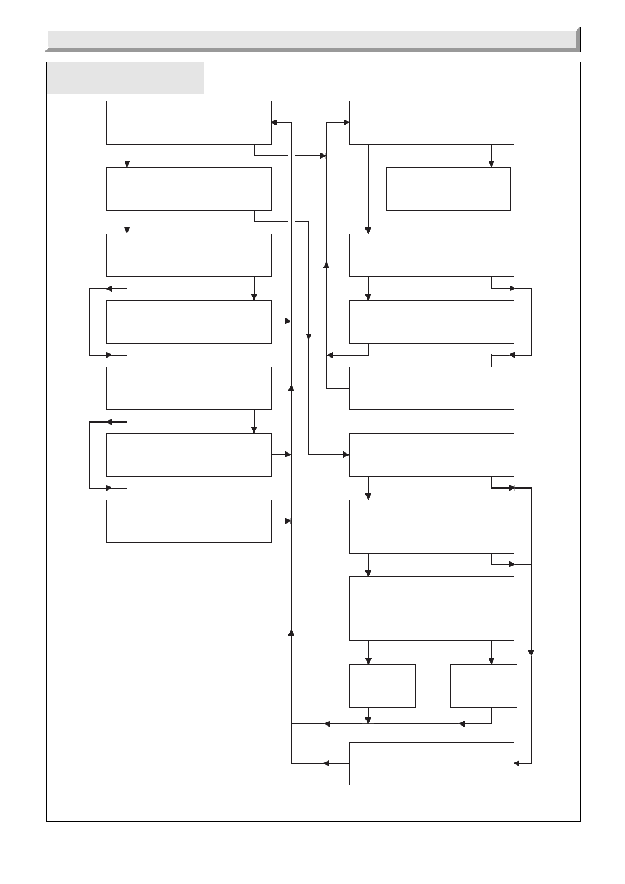
Check gas line - open all cocks,
rectify any blockages, purge out
any air. Does pilot light?
Apply match to pilot burner instead of
pressing piezo unit button.
Does pilot light?
Undo tubing nut at pilot burner.
Press multi-functional control knob.
Does gas flow freely?
Rectify blockage in pilot injector,
or renew pilot injector.
Undo tubing nut at pilot outlet
of gas valve. Press gas valve knob.
Does gas flow freely?
Change blocked pilot tube.
Change multi-functional control.
Does pilot stay alight when
multi-functional control knob is
released?
Does pilot flame
envelope thermocoupling?
Check aeration. If necessary -
Clean pilot, rectify blockage in pilot
injector, or replace.
Check thermocoupling circuit using
Thermocoupling Fault - Finding
diagram.
On pressing piezo unit button
is there a spark across
electrode gap?
Pull ignition lead off electrode.
Hold end of lead close to pilot
burner and operate piezo unit.
Is there a spark across gap?
Pull ignition lead off piezo unit.
Using blade of a screwdriver, touch
unit chassis and leave approx.
4mm gap from connection tag on
piezo unit. Operate piezo.
Is there a spark across gap?
Change
piezo unit.
Change
ignition unit.
Check electrode gap. Reposition, or
replace electrode as necessary.
PILOT SATISFACTORY
9 Fault Finding
PILOT WILL NOT LIGHT
START HERE
Diagram 9.1
0032M
22
221791B
9 Fault Finding
Diagram 9.2
Diagram 9.2A
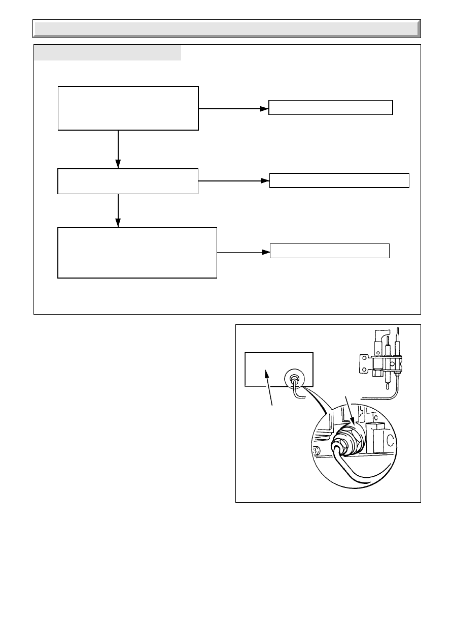
THERMOCOUPLE FAULT FINDING
4634
Is the connection between the
thermocouple and the multi-functional
control clean and tight ?
See diagram 9.2A, "Connection A"
Clean contacts and re-connect
Is the pilot flame correct length?
Approxomately 12mm.
Check pilot injector and regulate pilot
Check the thermocouple output
(8-15mV, closed) or replace thermocouple.
Reference should be made to procedure 7,
British Gas Multimeter Instruction Book.
Does the pilot now stay alight ?
Change multi-functional control
YES
NO
YES
NO
NO
3816
MULTI-FUNCTIONAL
CONTROL
CONNECTION 'A'
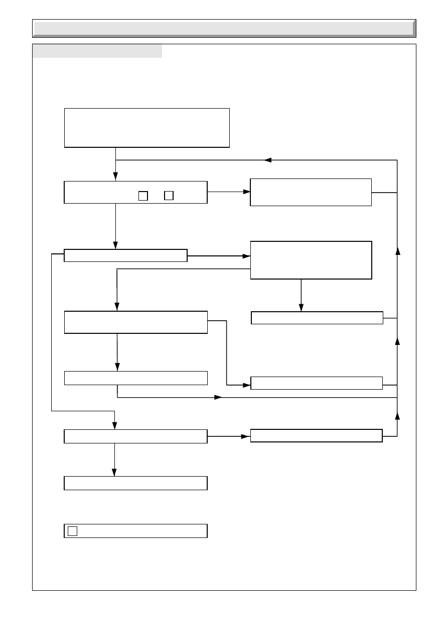
9.1 Pilot
Refer to Chart 9.1.
9.2 Thermocouple
To test the thermocouple a meter with a range of 6 to 30mV is
required together with a thermocouple interrupter test unit.
Refer to thermocouple fault finding chart, diagram 9.2 and
diagram 9.2A.
9.3 Electrical
Important. On completion of the service/fault finding task which
has required the breaking and remaking of the electrical
connections the earth continuity, polarity, short circuit and
resistance to earth checks must be repeated, using a suitable
multimeter.
Refer to Fault Finding, Wiring and Functional Flow diagram 9.3
and 9.4.
23
221791B
9 Fault Finding
ELECTRICAL FAULT FINDING
Diagram 9.3
9007
Isolate the supply. Gain access to the control
box, check all connections etc.
Restore supply. Using multimeter set at 230V. AC.
Check supply fuses. Renew if
necessary. If ok then fault lies withtin
remote controls. Inform customer.
With remote controls (if fitted) calling for heat
is there 230V between L &
N
Does main burner light.
Replace multi-functional control harness
YES
NO
YES
NO
Ensure that all services are available at the
appliance. ie. Gas, Electricity, Water.
Also turn control thermostat fully on and
check to see if pilot is lit.
Restore supply. Is there 230V between
"L" & "N" on multi-functional control?
Faulty multi-functional control. Renew.
Does pump run ?
CONTROLS IN ORDER
MAIN TERMINALS STRIP
Isolate supply. Remove gas valve
cover. Check continuity of multi-
functional control wire harness.
Continuity ok ?
Faulty control thermostat. Renew
Faulty pump, inform customer.
YES
YES
YES
YES
NO
NO
NO
24
221791B
9 Fault Finding
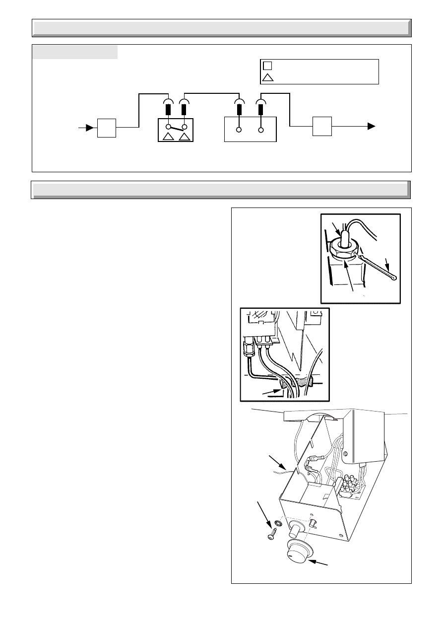
FUNCTIONAL FLOW
Diagram 9.4
Diagram 10.1
8050
3817
PHIAL POCKET
GLAND
SEAL
CONTROL KNOB
SECURING
SCREW (2)
CAPILLARY
SPLIT
PIN
CONTROL
THERMOSTAT
MULTI- FUNCTIONAL
CONTROL
PERMANENT
LIVE
230V ~ 50HZ
FUSED
AT 3A
L
N
br
bk
bl
N
MAIN TERMINAL STRIP
CONTROL THERMOSTAT
PHIAL
Replacement of parts must only be carried out by a competent
person.
Gain access as Section 8.1
Before replacing any parts isolate the boiler from the electrical
supply and turn the gas supply off at the gas service cock,
indicator slot to be vertical.
Unless stated otherwise, all parts are replaced in the reverse
order to removal.
After replacing any parts always test for gas soundness and if
necessary carryout functional check of controls.
10.1 Control Thermostat - diagram 10.1
Open and support the electrical control box, refer to Section 5.4.
Remove the control knob. Remove the electrical connections
from the control thermostat body.
Release the control thermostat body by unscrewing the two
screws and shakeproof washers in the front of the control box.
Remove the split pin and withdraw the control thermostat phial
from its pocket. Remove the control thermostat complete from
the boiler.
Re-assembly note. When fitting the control thermostat, make
sure that the control thermostat phial is covered with heat sink
compound and then fully inserted into the phial pocket and that
the capillary is within the gland seal. Remake the electrical
connections. There must be no kinks or sharp bends in the
capillary.
Make sure that the capillary is positioned so that it passes
through the cut out in the control box.
10.2 Pilot Burner and Pilot Injector
Proceed as relevant parts of Section 8.2 and 8.5.
10.3 Electrode - diagram 8.2
Proceed as relevant parts of Section 8.2, release the electrode
by removing the spring clip.
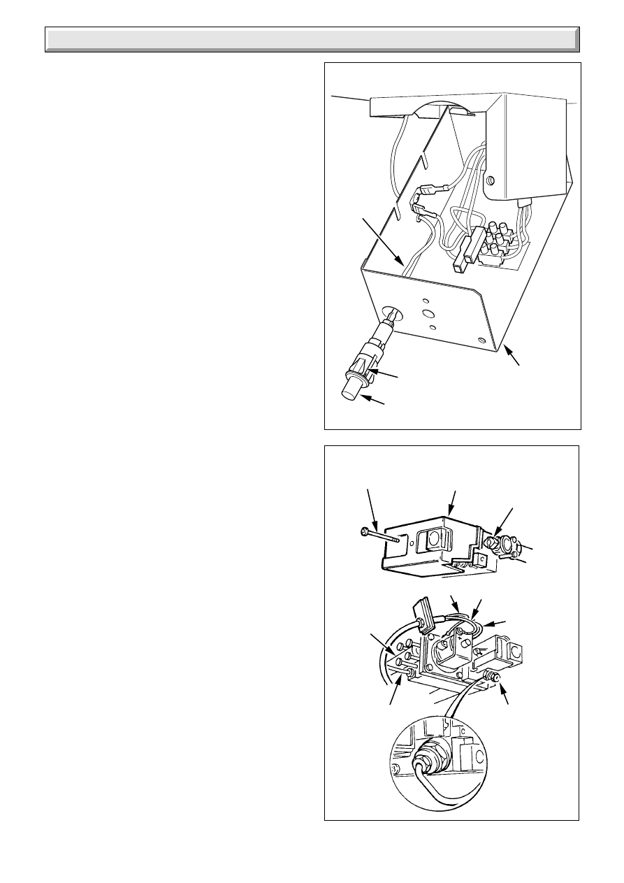
10.4 Piezo Unit - diagram 10.2
Open and support the electrical control box, refer to Section
5.4.
Disconnect the ignition lead at the piezo unit.
10 Replacement of Parts
8041
25
221791B
10 Replacement of Parts
Note: To ease the removal of the piezo unit it is advisable to
temporarily remove the boiler thermostat from the control box,
refer to Section 10.1.
Depress the retaining tabs and remove the Piezo unit.
10.5 Thermocouple - diagram 10.3
Proceed as relevant parts of Sections 8.2 and 8.5.
Unscrew thermocouple nut.
When refitting do not tighten the thermocouple nut more than a
quarter turn beyond finger tight.
10.6 Multi-functional Control - diagram 10.3
Remove the screw to release the multi-functional control cover.
Disconnect the electrical leads, thermocouple and pilot supply
pipe at the valve.
Undo the four screws each side of the multi-functional control to
release the gas service cock and the burner supply pipe, take
care not to damage the “O” ring seals.
Remake the connections.
Do not tighten the thermocouple nut more than a quarter turn
beyond finger tight.
It will be necessary to purge the pipework and the multi-
functional control before relighting, refer to “Commissioning”.
Refit multi-functional control cover.
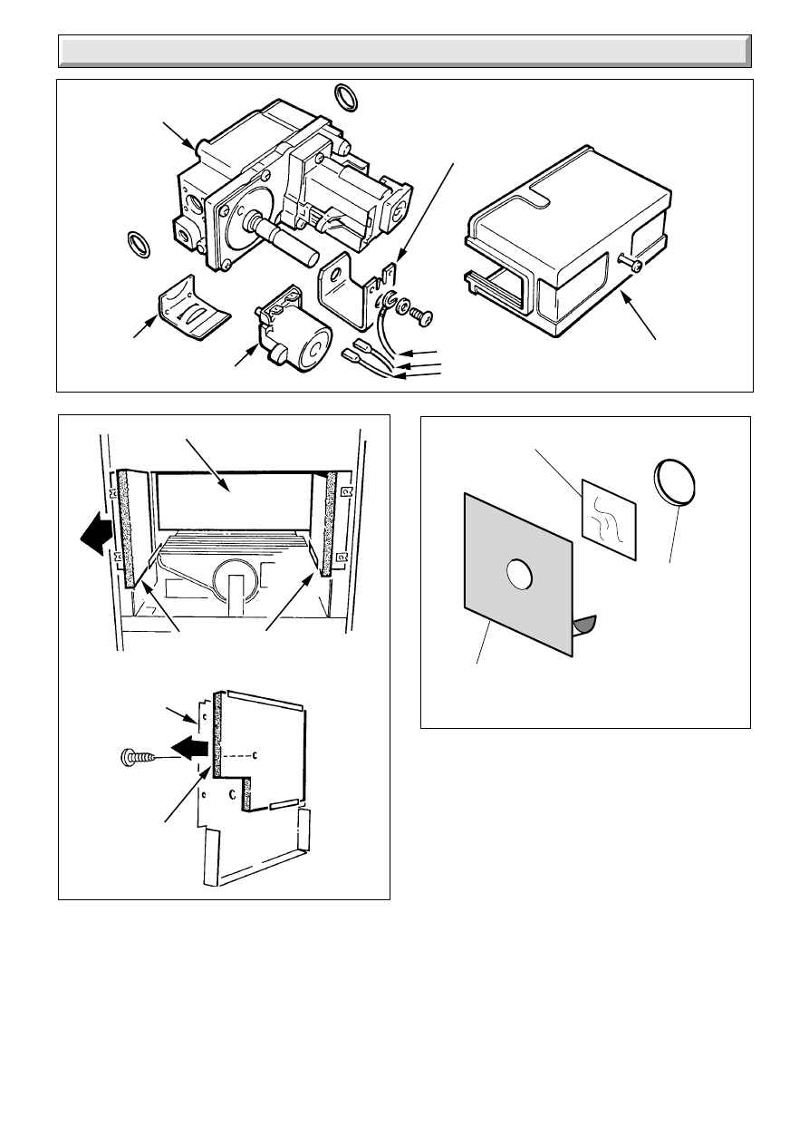
10.7 Solenoid - diagram 10.4
With the multi-functional control cover removed disconnect the
electrical leads, remove the retaining clip and solenoid.
10.8 Main Burner
Remove the main burner as Section 8.2.
10.9 Main Injector
Remove the main injector as Section 8.4.
10.10 Insulation - diagram 10.5
Combustion Chamber Front
Remove the combustion chamber front as Section 8.2. Remove
the retaining screw and slide the insulation out. .
Sides
Slide the insulation pads out.
Rear
With the side pads removed the rear pad can now be removed.
10.11 Viewing Window - diagram 10.6
Remove the old self adhesive aluminium foil gasket and the old
mica window. Replace with a new mica window. Peel off the
backing paper and secure with new self adhesive aluminium foil
gasket, see diagram 10.6. Ensure no air bubbles are trapped
underneath the foil.
Important
Make sure that the mica window fully covers the opening and
that the hole in the aluminium foil gasket is centred over
opening.
Diagram 10.2
Diagram 10.3
8039
3819
CONTROL
BOX
IGNITION
LEAD
RETAINING
TABS
PIEZO UNIT
COVER
BURNER
SUPPLY
PIPE
COVER
SECURING
SCREW
GAS
SERVICE
COCK
BLUE GREEN/YELLOW
BROWN
THERMOCOUPLE
NUT
PILOT SUPPLY
PIPE
26
221791B
10 Replacement of Parts
Diagram 10.4
Diagram 10.5
3821
SOLENOID
COVER
MULTI-FUNCTIONAL
CONTROL
SOLENOID
RETAINING
CLIP
SOLENOID
BRACKET
ELECTRICAL
CONNECTIONS
3820
SIDE INSULATION
PANELS
COMBUSTION
CHAMBER FRONT
COMBUSTION
CHAMBER FRONT
INSULATION
REAR INSULATION PANEL
Diagram 10.6
SELF ADHESIVE
ALUMINIUM FOIL
GASKET
MICA WINDOW
PEEL OFF
BACKING
PAPER
OPENING
(INSIDE FACE OF
THE BOILER
FRONT COVER)
7907
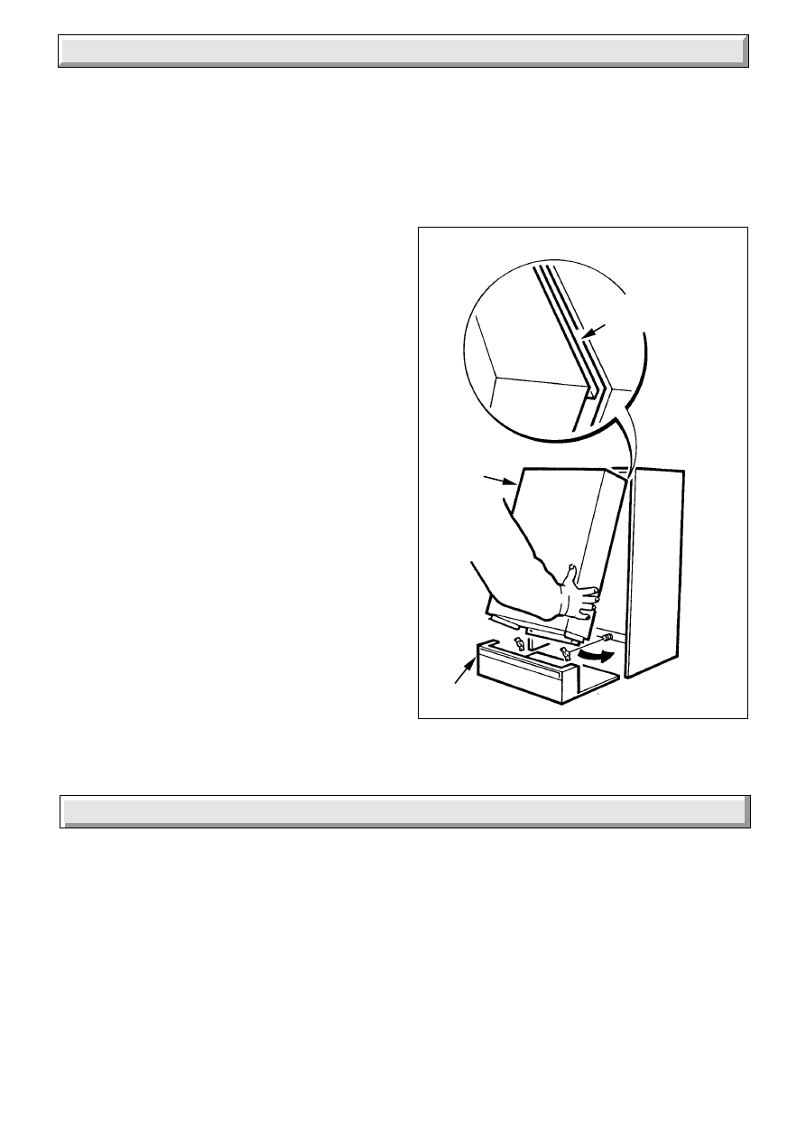
10.12 Case Seal
To remove the seal, carefully bend up the tabs.
Remove the seal, making sure that all the old adhesive is
removed.
When fitting the new seal, make sure that it fits into the corners
and has not buckled.
Carefully bend the tabs down.
27
221791B
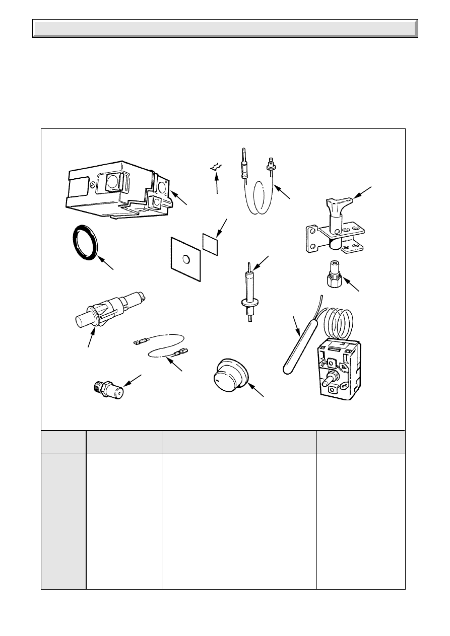
11 Spare Parts
Diagram 11.1
1
429549
Multi-functional control
312 926
2
208040
Joint ring
334 592
3
205701
Injector - 60BF
313 393
4
202432
Thermocouple
E00 999
5
K3580
Clip - thermocouple
390 983
6
203429
Pilot burner
379 021
7
202621
Spark electrode
379 020
8
WW4609
Ignition lead
136 464
9
800399
Thermostat - control
313 915
10
204687
Control knob
*********
11
202713
Piezo igniter
*********
12
801236
Mica window and gasket
7916
Key No
Part No
Description
GC Part No
11.1 Part Identification
The key number on the diagram and the list will help to identify
the part.
11.2 Ordering
When ordering any spare parts please quote the number and
description from the list together with the model name and serial
number.
If ordering from British Gas also quote the GC number of the
appliance and part.
1
5
8
6a
4
6
12
3
10
9
7
2
11

28
221791B
Because of our constant endeavour for improvement, details may vary slightly from those shown in these instructions.
Wyszukiwarka
Podobne podstrony:
Glow Worm installation and service manual Ultimate 50CF UIS
Glow Worm installation and service manual Ultimate 60CF UIS
Glow Worm installation and service manual Ultimate 40CF UIS
Glow Worm installation and service manual Ultimate 40BF UIS
Glow Worm installation and service manual Ultimate 50CF UIS
Glow Worm installation and service manual Ultimate 60CF UIS
Glow Worm installation and service manual Ultimate 40CF UIS
Glow Worm installation and service manual Ultimate 60CF UIS
Glow Worm installation and service manual Ultimate 50CF UIS
Glow Worm installation and service manual Hideaway 60BF UIS
Glow Worm installation and service manual Ultimate 30BF UIS
Glow Worm installation and service manual Hideaway 70CF UIS
Glow Worm installation and service manual Hideaway 80BF UIS
Glow Worm installation and service manual Hideaway 120BF UIS
więcej podobnych podstron