ISSN 1052-6188, Journal of Machinery Manufacture and Reliability, 2007, Vol. 36, No. 2, pp. 178–184. © Allerton Press, Inc., 2007.
Original Russian Text © A.D. Sergeev, 2007, published in Problemy Mashinostroeniya i Nadezhnosti Mashin, 2007, No. 2, pp. 86–94.
178
Nonlinear Interaction of the Pantograph of Electric Rolling
Stock and the Overhead Catenary Suspension System
A. D. Sergeev
Received June 21, 2006
Abstract
—
The description of the oscillatory dynamics of the discrete–continuous system over-
head catenary suspension–electric rolling stock pantograph is reduced to the Mathieu equation
with a periodic external influence. Analytical expressions for combinations of parameters of an
actual catenary suspension and an actual pantograph, whose variation changes the effective
properties of the pantograph, are obtained. The opportunity of theoretically selecting optimum
combinations of properties of an actual pantograph and an actual catenary suspension expands
the methods of purposeful suppression of undesirable self-oscillatory modes directly in the
course of electric rolling stock movement and allows pantograph dependability to be improved.
DOI:
10.3103/S1052618807020136
In connection with the necessity of increasing the working speeds of electric rolling stock movement on
main rail lines, one of the important problems of rail transport is reliability of current collection in a wide
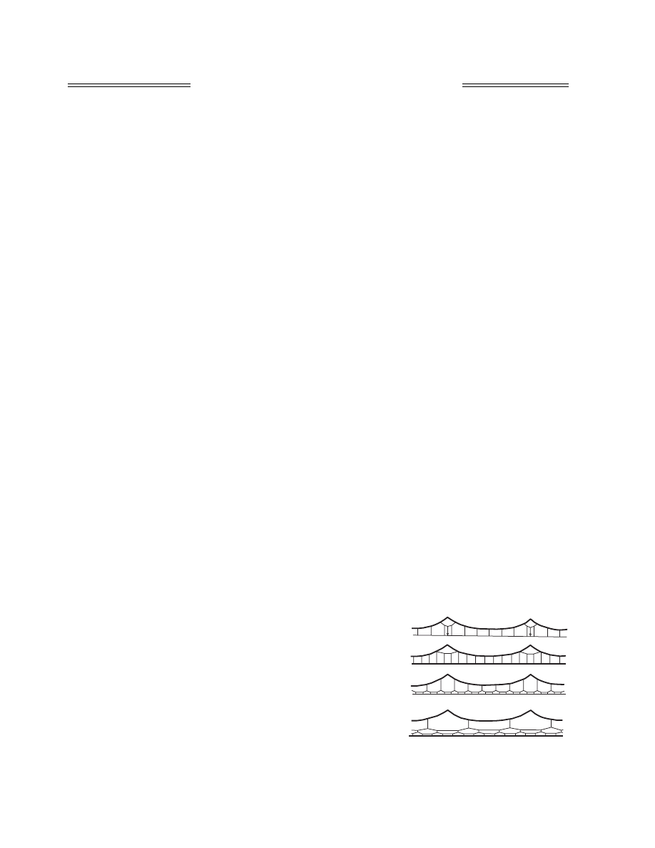
range of speeds [1–7]. Droppers (Fig. 1), holding a contact wire above the rails within the field of gravity,
are spatial one-way connections [4]. The designs of a trolley line suspension have periodically varying
effective pliability, which at certain speeds of carriage movement can become the cause of excitation of
parametric self-oscillations [8].
At present, the basis for analytical investigations of the dynamics of the overhead system–pantograph
system are semiempirical models in which a standard discrete cyclic circuit with several degrees of freedom
is taken as an example and the effective dynamic masses of the pantograph and the trolley line and the effec-
tive pliability of the catenary suspension are used as inertial and elastic parameters [5, 7]. The effective
dynamic masses and catenary suspension pliability, required for semiempirical design diagrams, are esti-
mated by processing experimental data, the pliability being estimated through static experiments.
Operating practice testifies that each of the catenary suspension arrangements (single-step with spring
filaments (Figs. 1a, 1b), double compensated (Fig. 1c), or the complicated three-step one used by the high-
speed railways of Japan (Fig. 1d) has advantages and disadvantages, which requires a search for a compro-
mise solution.
For example, the disadvantages of the three-step suspension arrangement (Fig. 1c), providing minimum
values of the coefficient of pantograph slide separation from the trolley line [4], are its cost and the deteri-
oration of its operating characteristics under conditions of icing or
snow sticking. The problem of the efficiency of making changes to
actual solutions becomes fundamentally important if the necessity of
correcting system parameters arises.
The most natural reasons for such correction are changes in
weather conditions, types of pantograph, and the speed modes of train
movement. With the designs already in operation, a description of sep-
arate important phenomena of the dynamics shown by the overhead
system–pantograph system that is well suited for practical needs can
be achieved by entering correction factors into semiempirical models.
However, this is achieved by the use for each phenomenon of a special
model that reliably predicts the results only within a fairly narrow
range of speeds. The problem of satisfactorily selecting the parameters
of a special computational model is rather acute inasmuch as the four
basic arrangements of a catenary suspension (Fig. 1) do not exhaust
EXPERIMENTAL MACHINE MECHANICS,
DIAGNOSTICS, AND TESTING
(a)
(b)
(c)
(d)
Fig. 1.
JOURNAL OF MACHINERY MANUFACTURE AND RELIABILITY
Vol. 36
No. 2
2007
NONLINEAR INTERACTION OF THE PANTOGRAPH
179
the versions of design solutions existing today, which num-
ber in the dozens.
The problem of choice is complicated by the circum-
stance that, in such systems as these, in addition to self-
oscillations arising at high train speeds in the vicinity of the
point at which the trolley line is contacted by the panto-
graph, localized resonant oscillations of the catenary sus-
pension may occur [9, 10]. Therefore, the identification of
the nature of experimentally observed resonance-like phe-
nomena is objectively complicated. Thus, it is extremely difficult to confidently identify on the basis of
experiments alone combinations of parameters of a multielement discrete–continuous system whose pur-
poseful variation would lead to an increase in the current collection reliability optimal for operation in a spe-
cific situation arising [11]. Let us consider a nonlinear computational model that substantially solves the
problem of correct and uniform mathematical description of the catenary suspension–pantograph system
within the whole speed range of modern rolling stock.
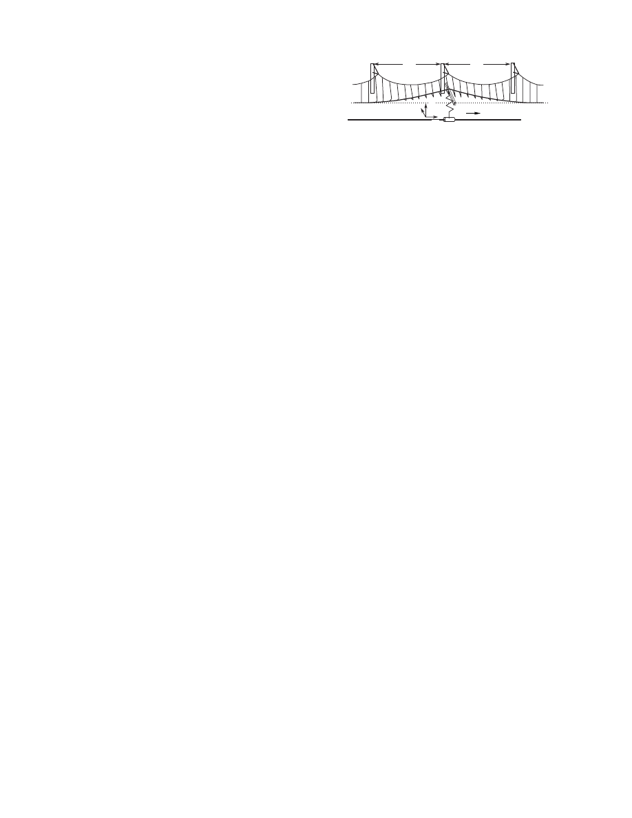
The dynamic phenomena accompanying the current collection process intended for high-speed rolling
stock may be analyzed by means of the multielement model (Fig. 2). It, to a large degree, allows one to fol-
low the complete spectrum of the influence resulting from varying this or that parameter of the catenary sus-
pension–pantograph system design by theoretical methods. The noninertial spring dropper is suspended
from nonextensible filaments situated along a rigid guide and is loaded with a transverse vertical loading
uniformly distributed lengthwise. The linear loading equals the weight per unit length of the trolley line.
With the 3D modeling of strains suffered by the trolley line, the suspended elastic line in the reference (not
strained) configuration is a zigzag broken line located in a horizontal plane. However, in this paper, displace-
ments of the trolley line along the direction of the unit vector
n
(pantograph) are not considered (Fig. 2);
therefore, the trolley line is modeled on a suspended straight line. This simplifies the description of dry fric-
tion forces at the point where the pantograph contacts the trolley line. The filaments holding the dropper
generally do not prevent displacements of its cross sections upwards, i.e., above the conventional zero mark;
however, the wires completely prevent deviations of its cross-sectional planes downwards. The distance
L
d
between supports is a suspension parameter accounting for the periodicity. Laid out in parallel with the
straight line is a guide rail along which the carriage moves, bearing a device contacting with the fixed drop-
per at one point. The role of the pantograph is played by a rectilinear inertial rod located horizontally and
pressed against the line by an elastic noninertial element (like a spring), the base of which is carried by the
carriage, moving strictly along the guide rail (Fig. 2). The axis of the rod is parallel with a horizontal plane
and orthogonal to the direction of the carriage’s speed, the pantograph being carried by the carriage. Relative
to the carriage, the rod can make only translational movements in the direction perpendicular to the plane
of the undeformed wire suspended from springs. The presence of dry friction is supposed at the point of
contact of the dropper and the rod.
Let us denote by
υ
the speed of displacement of the model element carrying the pantograph along the
guide rail, which we will consider constant.
Let the length of the rectilinear section of the dropper pretensioned and then secured in the dropper con-
tinuous suspension be denoted as
L
. Hereafter, we assume that
L
=
L
d
since the zigzag trolley wire [1] is
ignored. Let the Lagrangian coordinate of the point of contact of the pantograph and the dropper, reckoned
along the trolley line, be denoted as
s
p
. The position of the pantograph inertial element is set by the vector
function
R
p
(
t
):
R
p
=
R
0
p
+
υ
(
t
–
t
0
)
t
+
W
k
,
R
0
p
= const,
=
υ
t
+
,
=
.
Let us denote by
N
=
N
k
a vertical force (not associated with the presence of friction) acting from the
side of the stretched trolley wire on the pantograph inertial element, having weight
m
. In addition to gravity
mg
(where
g
stands for the acceleration of the field of gravity), the pantograph inertial element is acted upon
by some force directed along the unit vector
k
from the side of its elastic element. Let us use the defining
equation
F
e
= –
c
(
W
–
W
0
)
. The parameter
W
0
corresponds to the pantograph’s position above the plane of
the elastic–inertial line when its elastic element is not strained. In simulating dry friction at the point of con-
tact, we shall accept the friction force acting upon the pantograph as directed opposite the carriage move-
ment velocity. The concentrated friction force acting on the trolley line at the point of pantograph contact is
directed along the unit vector
t
. At the point of trolley wire–pantograph contact, breaking away is possible
R˙
p
W˙ k R
˙˙
p
W
˙˙k
k
t
n
L
d
L
d
v
Fig. 2.

180
JOURNAL OF MACHINERY MANUFACTURE AND RELIABILITY
Vol. 36
No. 2
2007
SERGEEV
owing to a unilateral constraint, and the condition
N
≤
0
is accepted as satisfied. Therefore, the defining
equation for the friction force magnitude
F
fr
≥
0
is taken as
F
fr
=
f
fr
|
N
|
, where
f
fr
is the coefficient of dry fric-
tion.
The equation of the vertical movement of the pantograph inertial element is taken as
=
N
–
c
(
W
–
W
0
) –
mg
.
At the point of contact with the pantograph, the dropper cross-section radius vector has the form
R
(
s
p
(
t
),
t
) =
[
s
p
(
t
) +
u
(
s
p
,
t
)]
t
+
w
(
s
p
,
t
)
k
, where the function
u
(
s
p
,
t
)
describes the dropper cross-section axial displacement
from the undeformed configuration at the contact point;
w
(
s
p
,
t
)
stands for the dropper transverse displace-
ment.
The following expression for dropper dynamic tensioning is taken as correct [12]:
ε
=
u
' +
w
'
2
/2,
A
ε
T
0
, ()' =
∂
/
∂
s, where A is the tensioning rigidity of the trolley line; the static strain
ε
0
, accounted for by its
pretensioning by the force T
0
(where T
0
= A
ε
0
), is supposed to be far larger than the additions caused by the
action of the pantograph.
We will write the dropper strain in the segment wherein no vertical transverse sagging is present due to
the effects of unilateral constraints as follows:
(1)
where
ρ
is the linear weight of the trolley line proper. In order to prevent infinite longitudinal displacements
in an unlimited system in response to longitudinal loading at the contact point, let us consider that the system
of distributed unilateral constraints–suspenders in the area that is not raised elastically resists longitudinal
displacements of the trolley line according to a linear law by analogy with a Winkler foundation. The cor-
responding elastic parameter of the model is designated by k
τ
.
The extensible dropper equation for the segment where the deflection is positive and there is no influence
of unilateral constraints because there is vertical compression is described by two equations [13]. In the
equations, we will take into account the weight effects of the unloaded droppers from which the trolley line
hangs. We consider that the total weight per unit length of the trolley wire and the unloaded system of sus-
pending droppers
ρ
w
g raised by the pantograph above the zero level surface is independent of the height to
which the trolley line is raised. Having included the impact of the weight of unloaded droppers on the trolley
line into the density of the external weight load per unit length on an elastic–inertial line, we will consider
[4, 5] that
ρ
w
=
ρ
w
(s) is a periodic function of angular position with the period L
d
:
ρ
w
(s) =
ρ
0
+
ρ
1
Φ
(s),
Φ
(s) =
Φ
(s + nL
d
), n = 1, 2, …,
= 0.
We assume that, for each catenary suspension design, the factors
ρ
0
and
ρ
1
and the function
Φ
(s) are
known. The accepted assumptions allow us to write the following set of equations for the segment of trolley
wire raised by the pantograph:
(2)
Having integrated the equations for an extensible dropper in the vicinity of the point of contact with the
pantograph, we obtain the interface conditions
(3)
(4)
At the point of conjugation of displacements of the elastic–inertial line and the pantograph, the vertical
component of displacement of the wire cross section is determined by the current height of the pantograph
above the trolley wire stringing plane and the vertical motion w
' is included in the equation of motion of the
pantograph inertial element.
Without taking into consideration gravity, a discussion of methods for stringing the trolley line is mean-
ingless, and in what follows we retain the presence of the gravity force in the model in description of trolley
mW
˙˙
ρ
u˙˙
Au''
k
τ
u,
w
–
0,
≡
=
Φ ξ
( ) ξ
d
s
s
L
d
+
∫
ρ
u˙˙
Au''
A 1
ε
0
–
(
)
w'w'',
ρ
w
˙˙
+
T
0
w''
ρ
w
s
( )
g.
–
=
=
A u'
1
ε
0
–
(
)
2
------------------w'
2
+
s
s
p
0
–
=
s = s
p
0
+
f
fr
N ,
N
–
T
0
w'
s
s
p
0
–
=
s = s
p
0
+
;
=
=
W
w s
p
t
,
(
)
,
mW
˙˙
cW
+
T
0
w'
s
s
p
0
–
=
s = s
p
0
+
cW
0
mg.
–
+
=
=
JOURNAL OF MACHINERY MANUFACTURE AND RELIABILITY
Vol. 36
No. 2
2007
NONLINEAR INTERACTION OF THE PANTOGRAPH
181
line strains. However, we will neglect the inertial components, supposing
that the left sides of Eqs. (1) and (2) are equal to zero. For the distribution
ρ
w
(s), a nondecreasing function of angular position may be found,
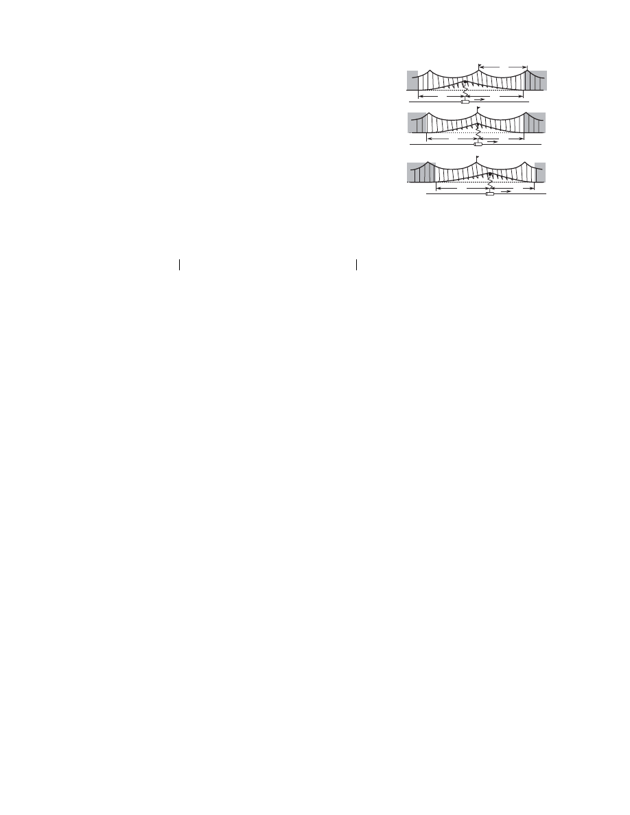
(5)
The integration in (5) gives the weight of the portion of the catenary
suspension somewhat to the left of the current coordinate s and raised by
the pantograph located at the point having the coordinate s
p
; s
p
– L
b
is the
Lagrangian coordinate at which the elastic line breaks away from the sur-
face behind the contact point (Figs. 3a–3c, t
1
, t
2
> t
1
, and t
3
> t
2
, respec-
tively). Let the Lagrangian coordinate of breaking away from the surface
before the contact point be denoted as s
p
+ L
f
. We obtain a description of
the dropper strain to the left of the pantograph contact,
Ψ
b
s
p
L
b
s
, ,
(
)
ρ
w
ξ
( ) ξ
.
d
s
p
L
b
–
s
∫
=
(6)
It can be seen that ignoring the inertial terms in (1) and (2) enables us to obtain an obvious expression
for longitudinal deformations of a trolley wire from (6) through w
' and the transverse loading. Thus, it
appears that the longitudinal strains of the raised segment of the trolley wire in the given model are com-
pletely determined by the segment’s transverse displacements. We shall not consider these displacements.
There are no concentrated loadings present at the point at which the trolley wire breaks away from the
zero level surface behind the contact point; therefore, the trolley line should have a zero transverse deflection
at this point and a zero derivative of angular position due to the lateral conductor. In view of this, by repeat-
edly integrating the transverse strains from Eq. (6), we obtain
(7)
Relationship (7) when s
= s
p
and w
(s
p
) = W gives the equation for finding the value of L
b
, which deter-
mines the position of the point at which the trolley line breaks away from the surface behind the contact
point (Fig. 3). Similarly, we estimate the value of L
f
, which determines the position of the point at which the
trolley line breaks away from the surface ahead of the contact point. Thus, we have two equations for deter-
mining the area within which the trolley line is raised above the zero level surface
(8)
After estimating L
b
and L
f
from relationship (6) and the analogous relationship for the area before the
pantograph, we estimate the values of w
' to the right and left of the contact point. The value of the abrupt
change w' at the point of the Lagrangian coordinate s
p
is assessed through the pantograph rise magnitude W
and enters differential equation (4).
The main features of the differential equation for movement of the pantograph not losing contact with
the trolley line can be seen by implementing
Φ
(s). Inasmuch as generalization to any periodic distribution
of the weight of the catenary suspension is rather obvious, we will confine ourselves to a very simple situ-
ation and for definiteness set
Φ
(s) = cos2
π
s
/L
d
. Performing the necessary integration, we insert the result
into (8) to determine L
b
. Then we rewrite the obtained equation through dimensionless unknown
η
b
= L
b
/L
d
as follows:
(9)
where
u' s
( )
u'
s
s
p
L
b
–
=
1
ε
0
–
(
)
2
------------------w'
2
s
( )
,
w' s
( )
–
w'
s
s
p
L
b
–
=
Ψ
b
s L
b
s
p
, ,
(
)
g
T
0
----------------------------------.
+
=
=
w s
( )
g
T
0
-----
Ψ
b
s
p
L
b
ξ
, ,
(
) ξ
,
s
d
s
p
L
b
–
s
∫
s
p
.
<
=
W
g
T
0
-----
Ψ
b
s
p
L
b
ξ
, ,
(
) ξ
,
W
d
s
p
L
b
–
s
p
∫
g
T
0
-----
Ψ
f
s
p
L
f
ξ
, ,
(
) ξ
.
d
s
p
s
p
L
f
+
∫
=
=
η
b
2
µ
2
π ζ
p
η
b
–
(
)
sin
π
----------------------------------------
η
b
–
µ
2
π
2
--------
2
π ζ
p
η
b
–
(
)
cos
2
πζ
p
cos
–
(
) η
0
2
–
+
0,
=
v
v
v
L
d
L
f
L
b
L
b
L
f
L
f
L
b
(a)
(b)
(c)
Fig. 3.
182
JOURNAL OF MACHINERY MANUFACTURE AND RELIABILITY
Vol. 36
No. 2
2007
SERGEEV
(10)
At
µ
= 0, the value of
η
b
0
=
η
0
is independent of
ζ
p
. Thus, we will seek the solution of (9) in the form of
a power expansion of the series expansion parameter
µ
:
(11)
Inserting (11) into Eq. (9), by comparing the coefficients at
µ
we obtain
(11a)
It is possible to continue obtaining coefficients A
nb
(
ζ
p
,
η
0
), but we will limit ourselves solely to
A
1b
(
ζ
p
,
η
0
). The position of the point at which the trolley line breaks away from the plane behind the panto-
graph gives the expression
(11b)
Similarly, the position of the point at which the trolley line breaks away from the plane ahead of the pan-
tograph is written
(11c)
Dimensional parameters L
b
and L
f
, corresponding to
η
b
and
η
f
, can be conveniently represented as
(12)
In the absence of pantograph bouncing (breaking away from the trolley line), the full differential equa-
tion for the movement of the pantograph interacting with the trolley line takes the form
(13)
By setting
ρ
1
= 0, we obtain from (13) the movement equation for a pantograph interacting with the ide-
ally homogeneous catenary suspension:
(14)
ζ
p
s
p
L
d
-----,
η
0
2
L
0
2
L
d
2
------,
L
0
2
2T
0
ρ
0
g
---------W ,
µ
ρ
1
ρ
0
-----
1.
=
=
=
=
η
b
η
0
A
1b
ζ
p
( )µ
A
2b
ζ
p
( )µ
2
…
.
+
+
+
=
A
1b
ζ
p
η
0
,
(
)
2
π ζ
p
η
0
–
(
)
sin
2
π
------------------------------------
1
4
π
2
η
0
--------------
2
π ζ
p
η
0
–
(
)
cos
2
πζ
p
cos
–
(
)
.
–
=
η
b
η
0
µ
2
π ζ
p
η
0
–
(
)
sin
2
π
------------------------------------
1
4
π
2
η
0
--------------
2
π ζ
p
η
0
–
(
)
cos
2
πζ
p
cos
–
(
)
–
.
+
=
η
f
η
0
µ
2
π ζ
p
η
0
–
(
)
sin
2
π
------------------------------------
1
4
π
2
η
0
--------------
2
π ζ
p
η
0
–
(
)
cos
2
πζ
p
cos
–
(
)
+
.
+
=
L
b
L
c
L
a
,
L
f
–
L
c
L
a
,
L
c
+
2T
0
ρ
0
g
------------- W
L
d
2
π
------
ρ
1
ρ
0
-----
2
π
L
d
------ s
p
L
0
–
(
)
,
sin
+
=
=
=
L
a
1
2
π
2
--------
ρ
1
ρ
0
-----
L
d
2
L
0
------
π
L
0
L
d
---------
2
π
L
d
------ s
p
L
0
2
-----
–
⎝
⎠
⎛
⎞
.
sin
sin
=
mW
˙˙
cW
+
cW
0
mg
–
8T
0
ρ
0
g W
–
ρ
1
L
d
g
π
--------------
2
π
L
d
------ s
p
2T
0
ρ
0
g
------------- W
–
⎝
⎠
⎜
⎟
⎛
⎞
⎩
⎭
⎨
⎬
⎧
⎫
sin
–
=
–
ρ
1
gL
d
π
--------------
2
π
L
d
------
2T
0
W
ρ
0
g
------------------
L
d
2
π
------
ρ
1
ρ
0
-----
2
π
L
d
------ s
p
2T
0
W
ρ
0
g
------------------
–
⎝
⎠
⎜
⎟
⎛
⎞
sin
+
⎩
⎭
⎨
⎬
⎧
⎫
sin
×
2
π
L
d
------ s
p
ρ
1
2
π
2
--------
L
d
2
W
---------
g
2T
0
ρ
0
-------------------
π
L
d
-----
2T
0
W
ρ
0
g
------------------
⎩
⎭
⎨
⎬
⎧
⎫
2
π
L
d
------ s
p
T
0
W
2
ρ
0
g
----------------
–
⎝
⎠
⎜
⎟
⎛
⎞
sin
sin
+
⎝
⎠
⎜
⎟
⎛
⎞
⎩
⎭
⎨
⎬
⎧
⎫
.
cos
W
˙˙
*
ω
p
2
W *
8T
0
ρ
0
g
m
---------------------- W *
+
+
ω
p
2
W
0
g,
ω
p
2
–
c
m
----.
=
=
JOURNAL OF MACHINERY MANUFACTURE AND RELIABILITY
Vol. 36
No. 2
2007
NONLINEAR INTERACTION OF THE PANTOGRAPH
183
The static compression of the homogeneous overhead catenary suspen-
sion W
d
is determined by the expression
(14a)
In the absence of pantograph contact with the trolley line, Eq. (14)
becomes a classical oscillator equation, integration of which is trivial. At
the stage of pantograph–elastic line contact under initial conditions
W
∗
(t
0
) = W(t
0
) and
(t
0
) =
(t
0
), Eq. (14) allows analytical integration
as follows:
W
d
W
0
mg
c
-------
–
4T
0
ρ
0
g
c
2
------------------
2
W
0
mg
c
-------
–
⎝
⎠
⎛
⎞
2T
0
ρ
0
g
c
2
------------------
4T
0
2
ρ
0
2
g
2
c
4
---------------------
+
.
–
+
=
W˙ *
W˙
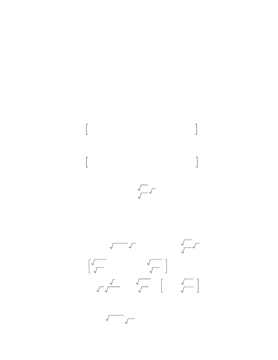
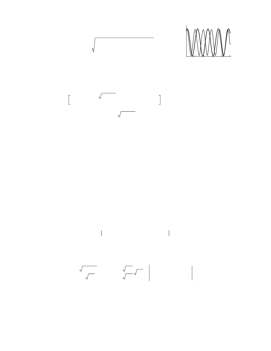
(15)
Inasmuch as solution (15) is inconvenient for analysis, Fig. 4 shows the results of numerical integration
of Eq. (14) at identical values of the elastic–inertial parameters of the oscillator and the overhead catenary
suspension and under the same initial conditions, but for a trolley line tension differing twofold. The initial
conditions are selected so that loss of contact between the pantograph inertial element and the dropper does
not occur. Such a line corresponds to a more tensioned elastic trolley line. The solutions obtained are not
sinusoids. By analogy with linear systems, it is possible to ascertain an increase in the effective rigidity of
the trolley line with growth of the trolley wire pretension. The number of extrema that fit within a fairly
extended interval of integration for the solution corresponding to a more tensioned dropper turns out to be
greater than for the solution corresponding to a less tensioned dropper.
The dependence of the static solution of Eq. (13) W
st
(s
p
) on the contact point coordinate s
p
is assessed by
the value of
ρ
1
. The parameters
,
, and
corresponding to the positive static solution W
st
(s
p
)
bounded from zero give, according to (10) and (12), the area of elevation of the trolley line (Fig. 3). We take
an equation of form (14), corresponding to a homogeneous overhead catenary suspension, as the first
approximation in describing the dynamics of the pantograph–nonhomogeneous overhead catenary suspen-
sion system. Using the ideology of the perturbation method [14], we will seek a solution in the form of the
sum of the static bias of Eq. (13) and a dynamic addition as follows:
.
(16)
By virtue of the boundedness of W
st
from zero, the solution of (16) admits the formal expansion in pow-
ers of H
(t) of summands of an equation of form (14). Preserving in the expansions only terms linear in H(t)
allows us to come to the following equation:
(17)
The equation with variable coefficients (17) describes the dynamic deviations of the pantograph from the
position that it would occupy if it moved along a nonhomogeneous bracket-arm contact suspension at an
infinitesimal speed. As the equation has been obtained, it is possible to predict the properties of its solutions
without going into the particulars of the formation of W
st
(s
p
). To this end, it will suffice to consider the pos-
itive function W
st
(s
p
) as varying periodically with s
p
changing linearly. Let an elementary periodic approxi-
mation of the type W
st
(s
p
)
≈
W
a
[1 +
µα
s
t
cos(2
π
s
p
/L
d
)],
α
st
~ O(1) stand for W
st
(s
p
).
β
0
ω
p
2
X
2
–
4 8T
0
ρ
0
g
3m
------------------------- X
3/2
–
2
ω
p
2
W
0
g
–
(
)
X
+
1/2
–
X
d
W t
0
( )
W
*
∫
t
t
0
,
–
=
β
0
W˙
2
t
0
( ) ω
p
2
W
2
t
0
( )
4 8T
0
ρ
0
g
3m
-------------------------W
3/2
t
0
( )
2
ω
p
2
W
0
g
–
(
)
W t
0
( )
.
–
+
+
=
L
0
st
L
c
st
L
a
st
W t
( )
W
st s
p
υ
t
=
H t
( )
W
0
,
H t
( )
W
0
W
st s
p
υ
t
=
+
=
H
˙˙
ω
p
2
ρ
1
ρ
0
-----
2
ρ
0
gT
0
m W
st
----------------------
2
π
L
d
------
υ
t
2T
0
ρ
0
g
------------- W
st
–
⎝
⎠
⎜
⎟
⎛
⎞
cos
–
⎩
⎭
⎨
⎬
⎧
⎫
s
p
υ
t
=
H
+
υ
2
W
0
-------
∂
2
W
st
∂
s
p
2
-------------
s
p
υ
t
=
.
–
=
W
*
0.5 1.0
2.0
1.5
2.5
t–t
0
Fig. 4.

184
JOURNAL OF MACHINERY MANUFACTURE AND RELIABILITY
Vol. 36
No. 2
2007
SERGEEV
Using the accepted approximation and leaving only the summands linear in
µ
in (18), we come to the
equation
(18)
Equation (18) is the Mathieu equation with a periodic external influence, well known in the literature
[15].
Having referred to the diagram of areas of stability of the Mathieu equation, known as the Ince-Strutt
diagram [15], it is arguable that (13) and (18) allow self-oscillatory solutions. The constructed nonlinear
analytical description of the overhead catenary suspension–pantograph system is obtained with weaker
restrictions imposed on the properties of unknown functions than is the case in the standard discrete com-
putational models. The nonlinear description theoretically predicts that the existence of self-oscillatory
modes of pantograph–trolley line system movement is quite real along with quasi-resonant ones. It is exact
in the sense that all parameters of Eqs. (13) and (18) can be unambiguously determined by the parameters
of real technical devices and do not require experimental correction.
Thence follows an important conclusion, from the viewpoint of applications, regarding the possibility of
controlling pantograph properties in an Ón-line mode with the aim of preventing undesirable dynamic
modes in the pantograph–overhead catenary suspension system. Having obvious representations for the
coefficients of the Mathieu equation, it is possible to check in what mode an actual overhead catenary sus-
pension–pantograph system is at the current value of rail carriage speed. This allows one to ensure, using
the control system, the theoretically greatest possible detuning of the system operating mode from the insta-
bility zone.
REFERENCES
1. Vlasov, I.I. and Markvard, R.T., Kontaktnaya set’ (Overhead System), Moscow: Transport, 1961.
2. Plaks, A.V., Mathematical Simulation of Catenary Suspension and Pantographs of Electrical Rolling-Stock, Izv.
Vyssh. Uchebn. Zaved. Elektromekh., 1966, no. 2, pp. 251–259.
3. Fraifel’d, A.V., Markov, A.S., and Tyurnin, G.A., Ustroistvo, montazh i ekspluatatsiya kontaktnoi seti (Construc-
tion, Wiring, and Operation of Overhead System), Moscow: Transport, 1967.
4. Belyaev, I.A., Vzaimodeistvie tokopriemnika i kontaktnoi seti pri vysokikh skorostyakh dvizheniya (Interaction of
Pantograph with Overhead System at High Speeds of Movement), Moscow: Transport, 1968.
5. Belyaev, I.A. and Vologin, V.A., Vzaimodeistvie tokopriemnika i kontaktnoi seti (Interaction of Pantograph and
Overhead System), Moscow: Transport, 1983.
6. Bauer, K.H., Seifert, R., und Kie
ßling, F., Weiterentwicklung der Oberleitungen für höhere Fahregeschwind-
igkeiten, Esenbahntchnischau, 1989, no. 1/2.
7. Gukow, A.I., Kie
ßling, F., et al., Fahrleitungen elektrischer Bahnen, Stuttgart: Teubner, 1997.
8. Andronov, A.A., Vitt, A.A., and Khikin, S.E., Teoriya kolebanii (Theory of Oscillations), Moscow: Nauka, 1981.
9. Indeitsev, D.A. and Sergeev, A.D., Localized Oscillations of the “Elastic Guide-Moving Inertial Connection” Sys-
tem, in Analysis and Synthesis of Non-linear Mechanical Oscillatory Systems, St. Petersburg: 1998, pp. 154–162.
10. Sergeev, A.D., Interaction of Unidimensional Continuum with an Inertial Facility Moving over It, J. Applied
Mechanics and Technical Physics (AMTP), 2005, vol. 46, no. 4, pp. 8–97.
11. Mikheev, V.P., Sidorov, O.A., and Salya, I.A., Study and Wear Forecasting of Contact Pairs of Current Collection
Devices, Izv. VUZov. Elektromekhanika, 2003, no. 5, pp. 74–79.
12. Svetlitskii, V.A., Mekhanika gibkikh sterzhnei i nitei (Mechanics of Flexible Bars and Strands), Moscow: Mashi-
nostroenie, 1978.
13. Zhilin, P.A., Teoreticheskaya mekhanika. Fundamental’nye zakony mekhaniki (Theoretical Mechanics. Funda-
mental Laws of Mechanics), St. Petersburg: Izd. SPbGPU, 2003.
14. Naife, A., Metody vozmushchenii (Perturbation Methods), Moscow: Mir, 1979.
15. Khayasi, T., Nelineinye kolebaniya v fizicheskikh sistemakh (Nonlinear Oscillations in Physical Systems), Mos-
cow: Mir, 1968.
H
˙˙
c
m
---- 1
ρ
1
ρ
0
-----
2
ρ
0
gT
0
c W
d
----------------------
ω
d
t
β
d
–
(
)
cos
–
⎩
⎭
⎨
⎬
⎧
⎫
H
+
α
st
ρ
1
W
d
ρ
0
W
0
--------------------
ω
d
2
ω
d
t,
β
d
cos
2
π
L
d
------
2T
0
W
d
ρ
0
g
---------------------.
=
=
Wyszukiwarka
Podobne podstrony:
Interaction of fraternal birth order and handedness in the
US Patent 577,671 Manufacture Of Electrical Condensors, Coils And Similar Devices
Interactions of fibroblasts with soldered and laser
71 1021 1029 Effect of Electron Beam Treatment on the Structure and the Properties of Hard
cicourel, a v the interaction of discourse, cognition and culture
British Patent 11,293 Improvements relating to the Utilization of Electromagnetic, Light, or other l
English Summary of The Invisible Rainbow A History of Electricity and Life 3
A Pragmatic Introduction to the Art of Electrical Engineering
British Patent 13,563 Improvements in, and relating to, the Transmission of Electrical Energy
British Patent 14,550 Improvements relating to the Insulation of Electric Conductors
British Patent 14,579 Improvements in and relating to the Transmission of Electrical Energy
British Patent 2,812 Improvements in Methods of and Apparatus for the Generation of Electric Current
Evans LINK BETWEEN THE SACHS AND O(3) THEORIES OF ELECTRODYNAMICS
The use of electron beam lithographic graft polymerization on thermoresponsive polymers for regulati
British Patent 6,502 Improvements relating to the Generation and Distribution of Electric Currents a
The effect of the interaction of various spawn grains with different culture medium on carpophore
Dyson, Rebecca M i inni Interactions of the Gasotransmitters Contribute to Microvascular Tone (Dys)
więcej podobnych podstron