
SECTION : 9T
REMOTE KEYLESS ENTRY AND
PERIMETER/ULTRASONIC ANTI–THEFT SYSTEM
CAUTION : Disconnect the negative battery cable before removing or installing any electrical unit or when a tool
or equipment could easily come in contact with exposed electrical terminals. Disconnecting this cable will help
prevent personal injury and damage to the vehicle. The ignition must also be in LOCK unless otherwise noted.
TABLE OF CONTENTS
SPECIFICATIONS
9T–1
. . . . . . . . . . . . . . . . . . . . . . . . . .
FASTENER TIGHTENING SPECIFICATIONS
9T–1
.
SCHEMATIC AND ROUTING DIAGRAMS
9T–2
. . . . .
REMOTE KEYLESS ENTRY AND ANTI–THEFT
SYSTEM (1 OF 2)
9T–2
. . . . . . . . . . . . . . . . . . . . . . .
REMOTE KEYLESS ENTRY AND ANTI–THEFT
SYSTEM (2 OF 2)
9T–3
. . . . . . . . . . . . . . . . . . . . . . .
CONTROL MODULE/RECEIVER CONNECTOR 9T–
4
WIRING HARNESS CONNECTORS
9T–4
. . . . . . . . .
MAINTENANCE AND REPAIR
9T–5
. . . . . . . . . . . . . . .
ON–VEHICLE SERVICE
9T–5
. . . . . . . . . . . . . . . . . . . . .
CONTROL MODULE/RECEIVER
9T–5
. . . . . . . . . . . .
SIREN
9T–5
. . . . . . . . . . . . . . . . . . . . . . . . . . . . . . . . . . .
FRONT DOOR TAMPER SWITCH
9T–7
. . . . . . . . . . .
REAR DECK LID TAMPER SWITCH
9T–7
. . . . . . . . .
HOOD OPEN SWITCH
9T–8
. . . . . . . . . . . . . . . . . . . . .
PASSWORD PROGRAMMING
9T–10
. . . . . . . . . . . . .
GENERAL DESCRIPTION AND SYSTEM
OPERATION
9T–11
. . . . . . . . . . . . . . . . . . . . . . . . . . . . . .
REMOTE KEYLESS ENTRY AND ANTI–THEFT
SYSTEM
9T–11
. . . . . . . . . . . . . . . . . . . . . . . . . . . . . . .
REMOTE LOCKING AND UNLOCKING
9T–11
. . . . . .
SECURITY INDICATOR
9T–11
. . . . . . . . . . . . . . . . . . . .
INTRUSION SENSING
9T–11
. . . . . . . . . . . . . . . . . . . . .
SIREN
9T–11
. . . . . . . . . . . . . . . . . . . . . . . . . . . . . . . . . . .
VEHICLE LOCATOR
9T–12
. . . . . . . . . . . . . . . . . . . . . .
AUTOLOCKING (SAFETY LOCK)
9T–12
. . . . . . . . . .
CONTROL MODULE/RECEIVER
9T–12
. . . . . . . . . . .
FAULT OR ALARM INDICATION
9T–12
. . . . . . . . . . .
PANIC BUTTON
9T–12
. . . . . . . . . . . . . . . . . . . . . . . . . .
SPECIFICATIONS
FASTENER TIGHTENING SPECIFICATIONS
Application
N
S
m
Lb–Ft
Lb–In
Hood Open Switch Mounting Screw
8
–
71
Siren Bracket Mounting Bolt
22
16
–
9T – 2
I
REMOTE KEYLESS ENTRY AND ANTI–THEFT SYSTEM
DAEWOO V–121 BL4
SCHEMATIC AND ROUTING DIAGRAMS
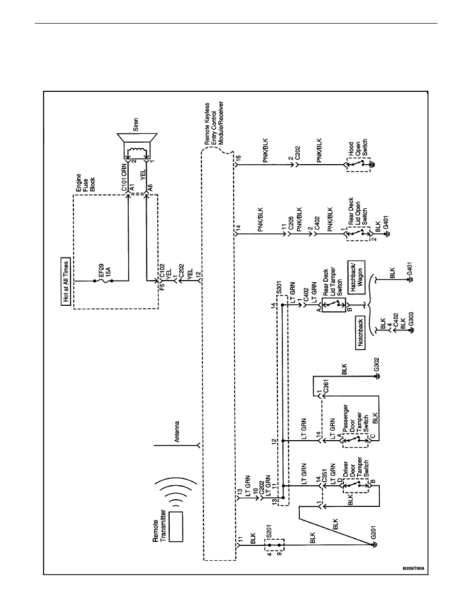
REMOTE KEYLESS ENTRY AND ANTI–THEFT SYSTEM (1
OF 2)
REMOTE KEYLESS ENTRY AND ANTI–THEFT SYSTEM 9T – 3
DAEWOO V–121 BL4
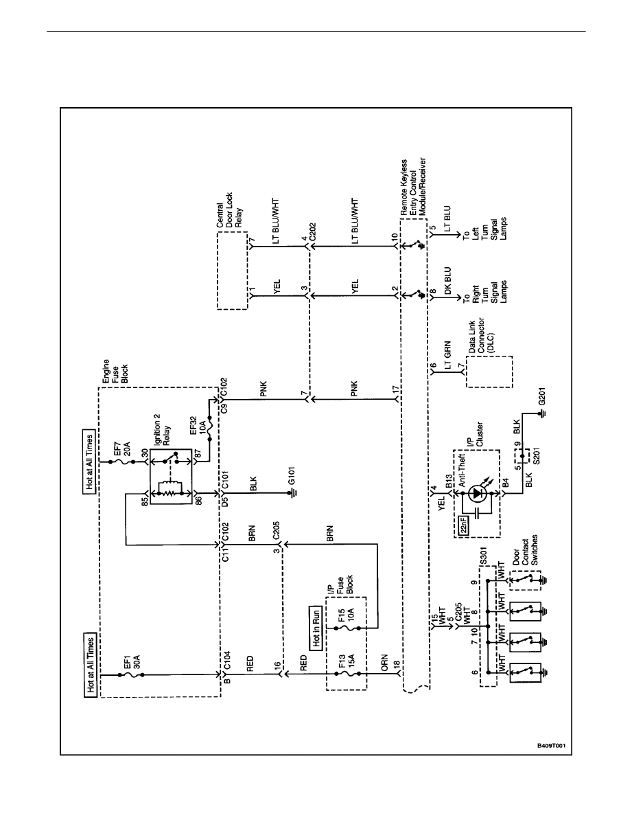
REMOTE KEYLESS ENTRY AND ANTI–THEFT SYSTEM (2
OF 2)
9T – 4
I
REMOTE KEYLESS ENTRY AND ANTI–THEFT SYSTEM
DAEWOO V–121 BL4
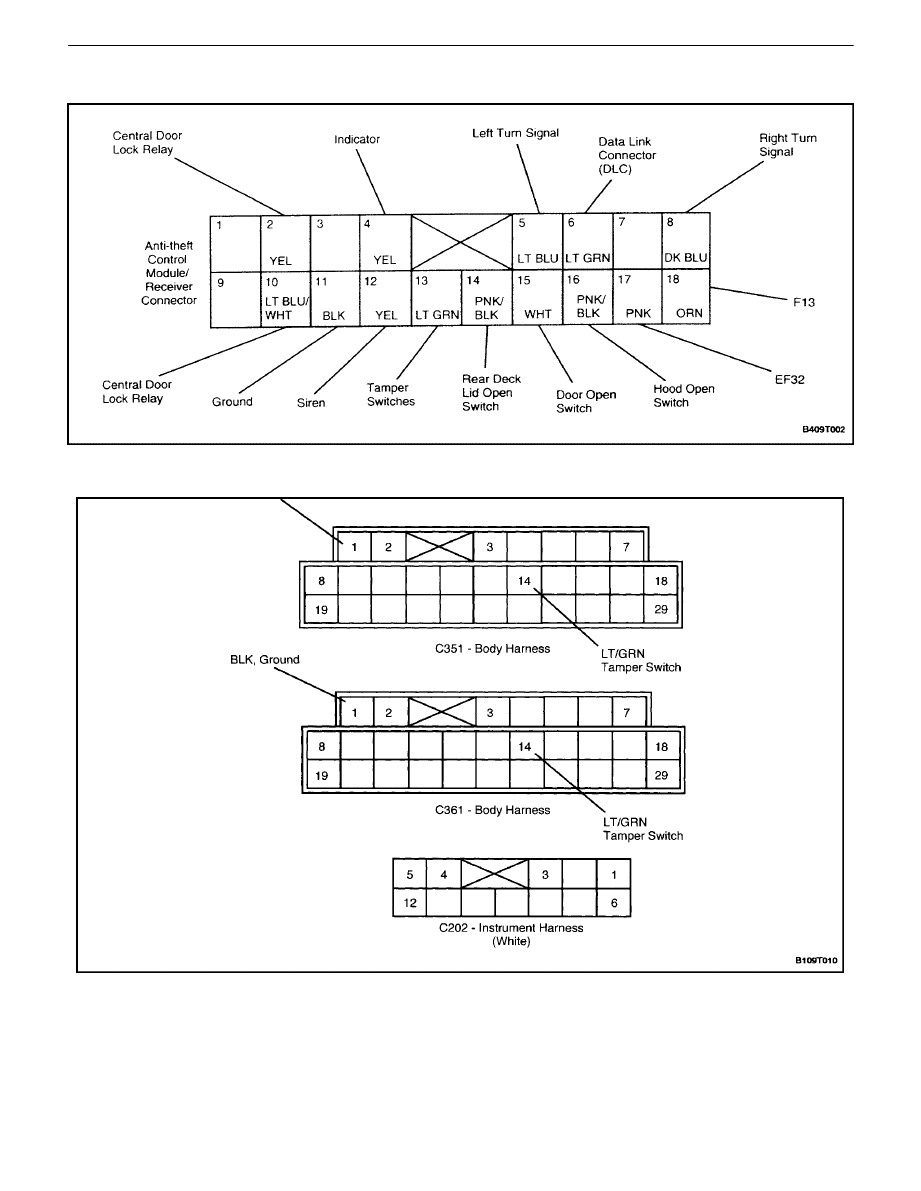
CONTROL MODULE/RECEIVER CONNECTOR
WIRING HARNESS CONNECTORS
REMOTE KEYLESS ENTRY AND ANTI–THEFT SYSTEM 9T – 5
DAEWOO V–121 BL4
MAINTENANCE AND REPAIR
ON–VEHICLE SERVICE
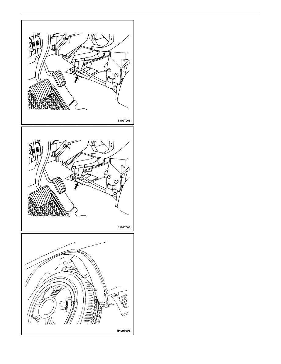
CONTROL MODULE/RECEIVER
Removal Procedure
1. Disconnect the negative battery cable.
2. Remove floor console left side forward trim panel.
Refer to Section 9G, Interior Trim.
3. Disconnect the control module/receiver electrical
connector.
4. Slide the control module/receiver toward the rear of
the vehicle and remove it.
Installation Procedure
1. Install the control module/receiver by sliding it onto
its bracket.
2. Connect the control module/receiver electrical con-
nector.
3. Install the floor console left side forward trim panel.
Refer to Section 9G, Interior Trim.
4. Connect the negative battery cable.
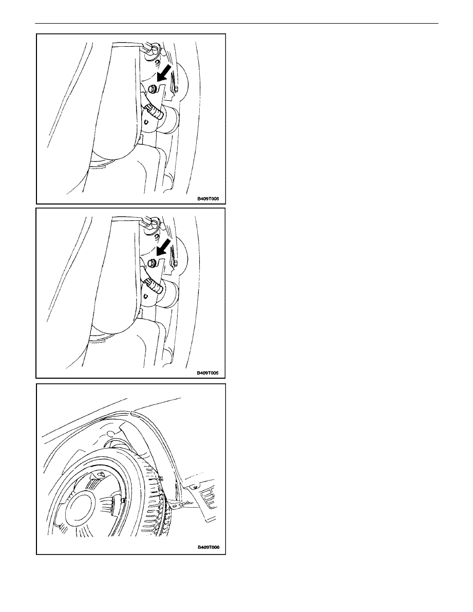
SIREN
Removal Procedure
1. Remove several screws to boosen the forward half
of the right front wheel well splash shield.
9T – 6
I
REMOTE KEYLESS ENTRY AND ANTI–THEFT SYSTEM
DAEWOO V–121 BL4
2. Remove the siren electrical connector.
3. Remove the siren bracket mounting bolt.
4. Remove the siren.
Installation Procedure
1. Install the siren on the siren bracket with the mount-
ing screws.
Tighten
Tighten the siren bracket mounting bolts to 22 N
S
m
(16 lb–in).
2. Connect the siren electrical connector.
REMOTE KEYLESS ENTRY AND ANTI–THEFT SYSTEM 9T – 7
DAEWOO V–121 BL4
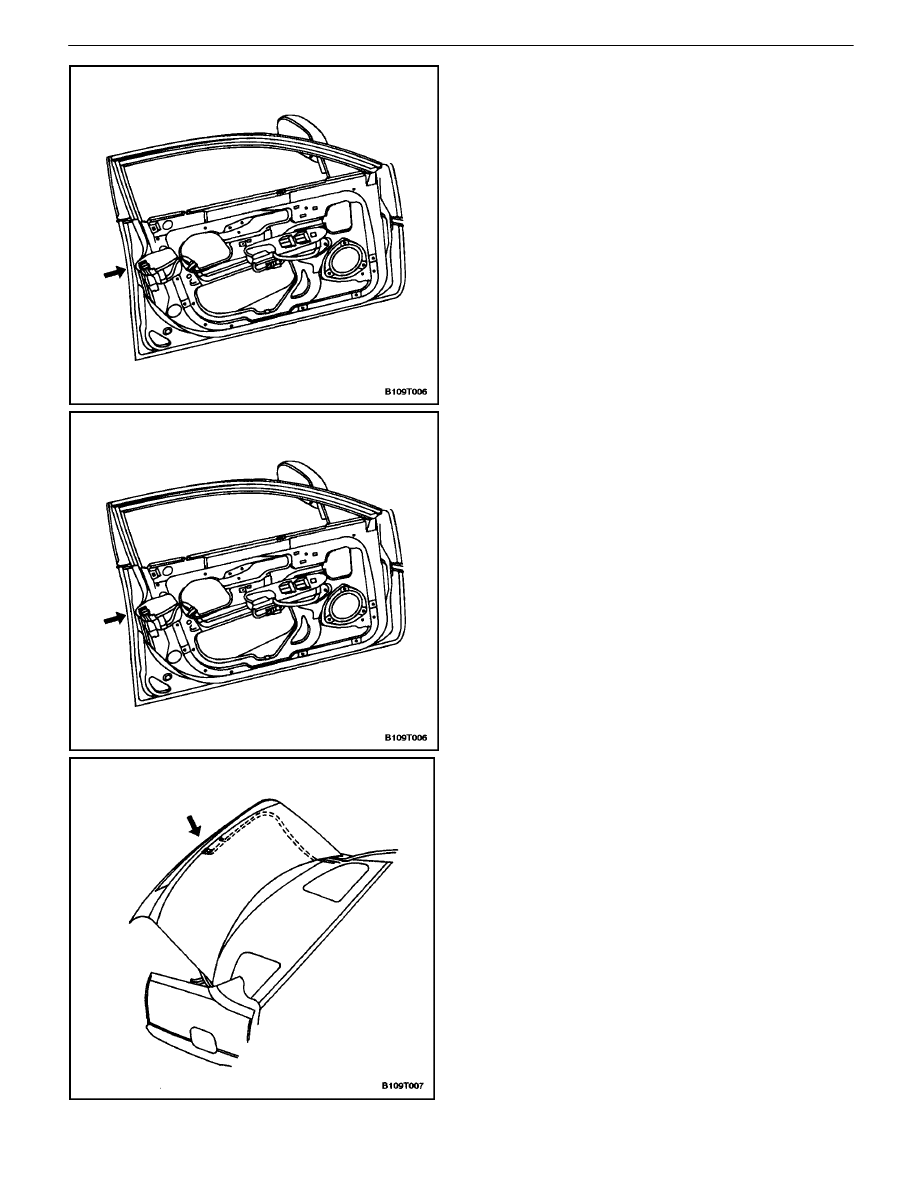
FRONT DOOR TAMPER SWITCH
Removal Procedure
1. Disconnect the negative battery cable.
2. Remove the front door trim panel. Refer to Section
9G, Interior Trim.
3. Disconnect the door tamper switch electrical con-
nector.
4. Remove the front door lock and the integral door
tamper switch. Refer toSection 9P, Doors.
Installation Procedure
1. Install the front door lock and the integral door tam-
per switch. Refer toSection 9P, Doors.
2. Install the door tamper switch electrical connector.
3. Install the front door trim panel. Refer to Section
9G, Interior Trim.
4. Connect the negative battery cable.
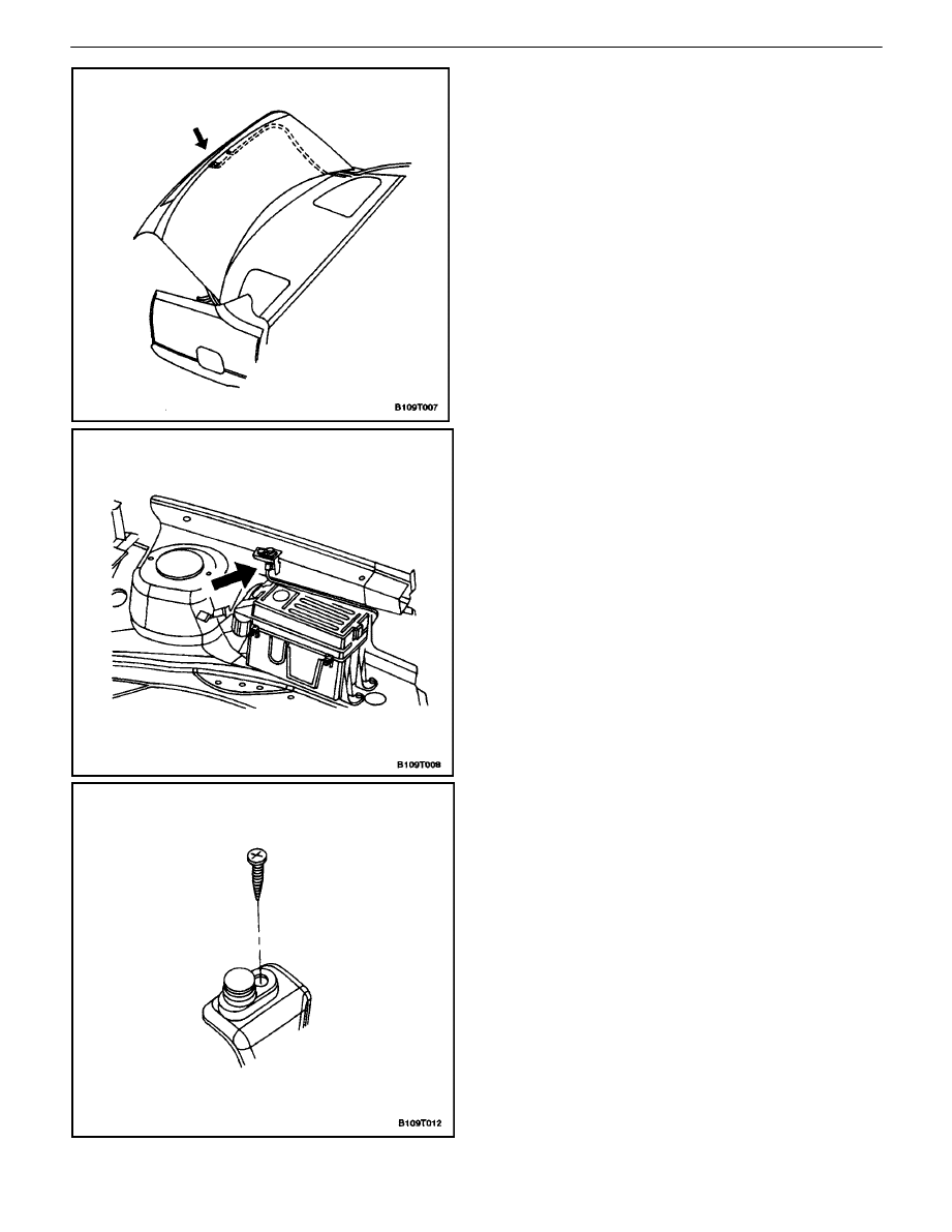
REAR DECK LID TAMPER SWITCH
Removal Procedure
1. Disconnect the negative battery cable.
2. Disconnect the rear deck lid tamper switch electri-
cal connector from the tamper switch.
3. Remove the rear deck lid tamper switch.
9T – 8
I
REMOTE KEYLESS ENTRY AND ANTI–THEFT SYSTEM
DAEWOO V–121 BL4
Installation Procedure
1. Install the rear deck lid tamper switch.
2. Connect the rear deck lid tamper switch electrical
connector to the tamper switch.
3. Connect the negative battery cable.
HOOD OPEN SWITCH
Removal Procedure
1. Disconnect the negative battery cable.
2. Disconnect the electrical connector from the hood
open switch.
3. Remove the mounting screw from the hood open
switch.
4. Remove the hood open switch.
REMOTE KEYLESS ENTRY AND ANTI–THEFT SYSTEM 9T – 9
DAEWOO V–121 BL4
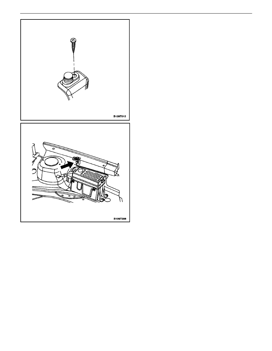
Installation Procedure
1. Install the hood open switch with the mounting
screw.
Tighten
Tighten the hood open switch mounting screw to 8
N
S
m (71 lb–in).
2. Connect the electrical connector to the hood open
switch.
3. Connect the negative battery cable.

9T – 10
I
REMOTE KEYLESS ENTRY AND ANTI–THEFT SYSTEM
DAEWOO V–121 BL4
PASSWORD PROGRAMMING
If a transmitter is lost or damaged, the control module/re-
ceiver must be re–programmed to communicate with a
new transmitter. The passwords recorded in the control
module/receiver should not be deleted when power is off
in the control module/receiver.
Each control module/receiver should be able to record five
passwords. The following method is used to record new
passwords in the control module/receiver:
1. Connect the scan tool to the assembly line diagnos-
tic link (ALDL) connector.
2. Turn the ignition ON.
3. Delete the current passwords.
4. Send the programming mode message to the con-
trol module/receiver.
5. Press any button of the transmitter to generate a
data code including a password which will be re-
corded by the control module/receiver. The control
module/receiver sends a response message to the
scan tool to indicate that the first password has
been recorded.
6. Press any button of the transmitter to generate a
data code including a password which will be re-
corded by the control module/receiver. The control
module/receiver sends a response message to the
scan tool to indicate that the second password has
been recorded.
7. Press any button of the transmitter three more
times until the control module/receiver has re-
sponded that the third, fourth, and fifth passwords
have been recorded.
8. Turn the ignition OFF.
9. Disconnect the scan tool.
The control module/receiver automatically leaves the pro-
gramming mode and switches to the normal operating
mode when either of the following conditions occurs:
S
The scan tool is disconnected from the ALDL.
S
Five passwords are recorded in the control module/
receiver.

REMOTE KEYLESS ENTRY AND ANTI–THEFT SYSTEM 9T – 11
DAEWOO V–121 BL4
GENERAL DESCRIPTION
AND SYSTEM OPERATION
REMOTE KEYLESS ENTRY AND
ANTI–THEFT SYSTEM
The remote keyless entry and anti–theft system can per-
form the following functions:
S
Remotely lock and unlock the vehicle doors with a
hand–held high–frequency transmitter.
S
Sense intrusion into the vehicle through the doors,
the trunk, or the hood.
S
Activate a warning to signal an intrusion.
S
Help the driver find the vehicle in a parking area.
S
Automatically
re–lock the doors if a door or the
trunk is not opened within 30 seconds after the ve-
hicle has been unlocked by the remote keyless
entry.
S
Communicate serial data to a scan tool to help
diagnose system faults.
The remote keyless entry and anti–theft system consists
of the following components:
S
Keyless entry and anti–theft control module/receiv-
er.
S
Security
indicator.
S
Rear deck lid open switch.
S
Rear deck lid tamper switch.
S
Front door tamper switches.
S
Door open switches.
S
Central locking unit.
S
Flashing turn signal lamps.
S
Siren.
S
Hood open switch.
REMOTE LOCKING AND UNLOCKING
The hand–held transmitter locks and unlocks the vehicle
doors by sending radio waves to the control module/re-
ceiver in the vehicle. The effective range of the transmitter
varies between 5 and 10 meters (approximately 16 to 32
feet), depending on whether or not objects such as other
vehicles are blocking the path of the radio waves.
The transmitter has a LOCK button and an UNLOCK but-
ton which only function when the ignition is OFF. Pressing
the UNLOCK button has the following effects:
S
The doors are unlocked.
S
The turn signal lamps flash twice.
S
The control module is disarmed.
Pressing the LOCK button has the following effects:
S
The doors are locked.
S
The turn signal lamps flash once.
S
The control module is armed.
The transmitter has a replaceable battery. The battery is
designed to last at least three years before replacement
is necessary.
SECURITY INDICATOR
There is a security indicator on the instrument panel. After
the LOCK button of the transmitter is pressed, the module
is placed in the armed mode, and the security indicator
flashes. The security indicator turns ON for 0.1 second
and OFF for 0.7 second. It then flashes at that frequency
until the control module/receiver is disarmed. If the vehicle
is equipped with an immobilizer, the security indicator is
connected to the immobilizer system instead of the key-
less entry/anti–– theft system.
INTRUSION SENSING
The anti–theft function is armed if the transmitter sends
the LOCK message to the control module/receiver when
the ignition is OFF.
When the hood, the door, or the rear deck lid is opened,
the hood open switch, the door open switch, or the trunk
open switch will change its input to ground. The alarm will
be activated if the hood open sensor, the door open sen-
sor, or the trunk open sensor changes its input to ground
before either of the following conditions occurs:
S
An UNLOCK message is received from the trans-
mitter.
S
The front door tamper switch or the rear deck lid
tamper switch indicates key operation by changing
its input to ground.
The alarm also will be activated if the ignition input is
changed to battery voltage before either of the following
conditions occurs:
S
An UNLOCK message is received from the trans-
mitter.
S
The front door tamper switch or the rear deck lid
tamper switch indicates key operation by changing
its input to ground.
SIREN
The remote keyless entry system is armed when the
LOCK message is received from the transmitter when the
ignition is OFF. When the system is armed, it will activate
the siren and flash the turn signals for 28 seconds if any
of the following conditions occurs:
S
A door is opened without using the key (front door
open switch input is changed to ground).
S
The rear deck lid is opened without using the key
trunk open switch input is changed to ground).
S
The hood is opened while the anti–theft system is
armed (hood open switch input is changed to
ground).
S
The ignition switch input is changed to battery volt-
age.
The siren is disarmed when any of the following conditions
occurs:

9T – 12
I
REMOTE KEYLESS ENTRY AND ANTI–THEFT SYSTEM
DAEWOO V–121 BL4
S
The door is opened with the key.
S
The rear deck lid is opened with the key.
S
The UNLOCK button or the LOCK button on the
remote transmitter is pressed within 2 seconds of
the beginning of the alarm. If the UNLOCK button
or the LOCK button is not pressed within 2 seconds
of the beginning of the alarm, the transmitter will
not stop the alarm.
VEHICLE LOCATOR
The remote keyless entry system assists the driver in lo-
cating the vehicle. When the vehicle is unlocked with the
remote control, the turn signals flash twice to indicate the
location of the vehicle. The duration of the flashes and the
length of time between flashes is used to indicate certain
vehicle conditions. Refer to ”Fault or Alarm Indication” in
this section.
AUTOLOCKING (SAFETY LOCK)
The remote keyless entry system features an autolocking
control. If the doors are unlocked with the remote transmit-
ter when the control module/receiver is in the armed
mode, the doors are automatically re–locked after 30 sec-
onds unless any of the following events occur:
S
The door is opened.
S
The ignition switch is turned ON.
S
The rear deck lid is opened.
S
The hood is opened.
CONTROL MODULE/RECEIVER
The remote keyless entry control module/receiver is con-
tained in the floor console. The module/receiver pro-
cesses signals from the remote transmitter and the intru-
sion sensors, and it activates the alarm if an intrusion is
detected. The control module/receiver also has a selfdiag-
nostic function which will display trouble codes. In order to
display trouble codes, a scan tool must be connected to
the assembly line diagnostic link (ALDL) connector.
The control module/receiver will not communicate with
transmitters from other vehicles because there are over
four billion possible electronic password combinations,
and passwords are not duplicated. The control module/ re-
ceiver has an attached antenna to detect signals from the
transmitter.
FAULT OR ALARM INDICATION
When the UNLOCK button on the remote transmitter is
pressed, the control module/receiver will flash the parking
lamps to indicate information about the remote keyless
entry and anti–theft system.
Normal Condition: If there has not been an intrusion, and
no fault has been detected, the control module/receiver
will signal a normal condition when the UNLOCK button is
pressed. The parking lamps will flash twice for 0.5 second,
with a 0.5 second pause between flashes.
Fault Indication: If there is a fault in the remote keyless
entry and anti–theft system, the control module/receiver
will signal the fault when the UNLOCK button is pressed.
The parking lamps will flash twice for 1 second, with a 0.5
second pause between flashes.
Alarm Indication: If there has been an intrusion since the
last time the LOCK button was pressed, the control mod-
ule/receiver will signal that there has been an intrusion
when the UNLOCK button is pressed. The parking lamps
will flash twice for 0.5 second, with a 1.5 second pause be-
tween flashes.
Alarm and fault information in the control module/receiver
will be erased the next time the controlmodule/receiver en-
ters the armed condition after receiving a LOCK message
from the transmitter.
PANIC BUTTON
In addition to the LOCK and UNLOCK buttons on the
transmitter, there is the panic button. This button is used
to activate the siren if a threatening situation occurs while
the driver is approaching the vehicle. If the panic button is
held down for 2 seconds, the siren will be activated for 30
seconds, and the parking lights will flash during that time.
Wyszukiwarka
Podobne podstrony:
M39t1 Remote Keyless Entry and Anti theft System
M39t2 Remote Keyless Entry and Anti theft System
M39t3 Imobiliser Anti theft System
05 6 F01 Anti theft System
20 E65 Anti Theft Alarm System
05c3 E70 Anti Theft Alarm System
system oświaty 12 13
03.Funkcje partii i systemy partyjne, 12.PRACA W SZKOLE, ZSG NR 4 2008-2009, PG NR 5
Systemy Zdrowotne 12
diagnostics Anti Theft
SYSTEM TRANSPORTOWY 12 STR, POLITECHNIKA POZNAŃSKA, LOGISTYKA, semestr IV, towaroznawstwo
73 Anti Theft and Door Locks
System wynagrodzeń (12 stron) LFBDZHBOSKEHONBTSPKKIGDUNEIXIVI6XW5K7RY
systemy motywacyjne (12 str), Zarządzanie(1)
system oświaty 12 13
więcej podobnych podstron