Q
R
2
0
Mr. T
23
30
12
18
17
16
15
14
37
39
38
3
7
6
5
20
26
21
22
40
13
4
2
25
24
8
1
28
27
11
31
19
10A
10D
10B
10C
10
29
10A
10F
10B
10E
10
9
32
36
33
34
35
Q
R
2
0
Mr. T
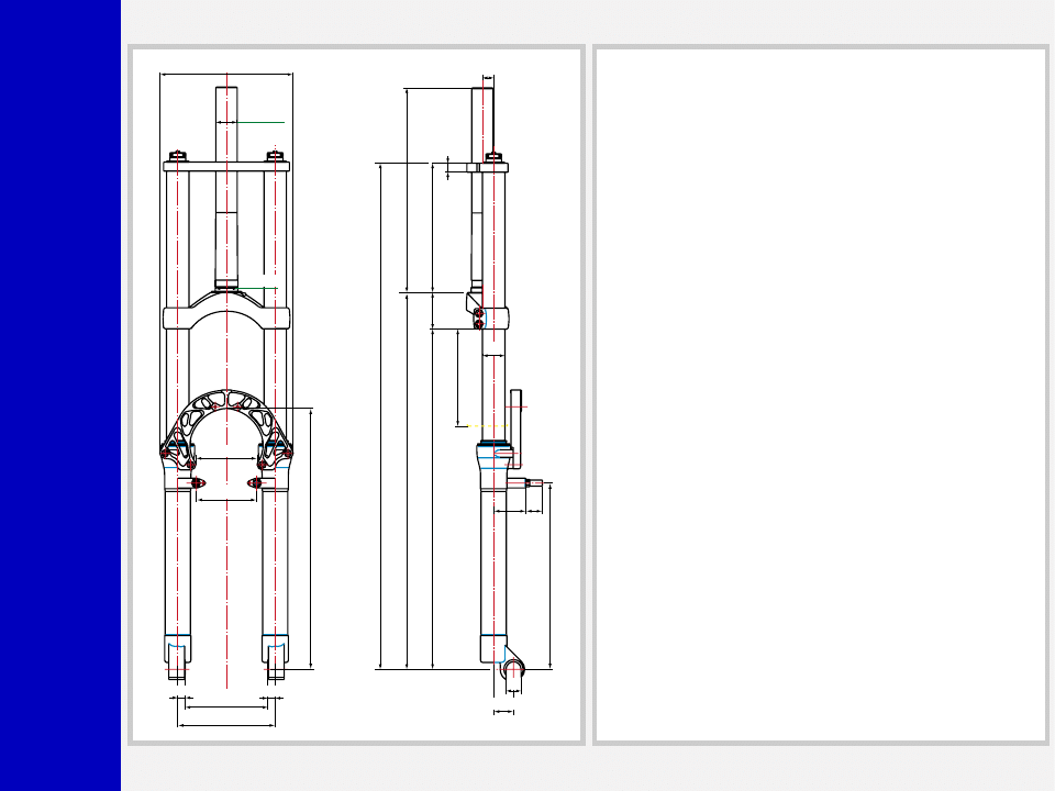
49
Ø28.6
±
0.1
Ø30
+0.05
0
273
172.4
TRA
VEL 130
Ø30
178
12
15
503
L.MAX=685.4
L.L.=675.4
L.MIN=545.4
454
±
2
±
2
82
80
22
43
248.5
26.5
20
10
130
10
110
Mr. T QR20 MY2000 cod.10211400
348
GENERAL
• The double clamp fork is specifically designed for Downhill use.
• The fork is damped by hydraulic cartridges for rebound and
compression damping.
• Rebound damping cartridge inside RH fork leg, compression
damping cartridge in LH fork leg.
• Spring pre-load and hydraulic damping adjustment controlled
via internal top mount adjusters.
• Stanchion tube secured to the crown and upper plate. The system
is equipped with full length 360º slider bushings giving this fork
an incredibly smooth stiction free stroke, in addition to un-
matched structural strength.
• Parts subjected to friction are cooled and lubricated by a
specially formulated oil.
• Brake caliper adapter kit available at request.
Steer tube: EASTON aluminum steer tubes available for 1 1/8”,
threadless.
Crown: Forged and CNC-machined BAM
❊
aluminum alloy.
Upper plate: CNC-machined T6-6082 alloy.
Arch: CNC-machined ERGAL alloy.
Stanchions: Anodized EASTON aluminum with variable butting.
Springs: Constant pitch springs.
Sliders: Cast and CNC-machined BAM
❊
aluminum alloy.
Slider bushing: Full length guide bushing composed of a copper
base and impregnated with a anti-friction coating.
Seals: Computer designed oil seals guarantee the highest quality
seals available.
Oil: Specially formulated oil which eliminates foaming and viscos-
ity breakdown while providing complete stiction-free performance.
Fork leg oil: 170 cc type EBH 16- SAE 7.5.
❊
BAM: Bomber Aerospace Material.
Special alloy extracted from aerospace material.

Q
R
2
0
Mr. T
GENERAL RULES FOR A
CORRECT OVERHAULING
AND MAINTENANCE
1. Where specified, assemble and disas-
semble the shock absorption system
using the MARZOCCHI special tools
only.
2. On reassembling the suspension sys-
tem, always use new seals.
3. If two screws are close one to the other,
always tighten using a 1-2-1 sequence.
In short, screw the first screw just up to
the point it is well tightened, then tighten
the second screw and then go back to
the first one and screw it tighter.
4. Clean all metal parts with a special,
preferably biodegradable solvent, such
as trichloroethane or trichloroethylene.
5. Before reassembling, lubricate all parts
in contact with each other using sili-
cone fat spray.
6. Always grease the conic seal rings
before reassembling.
7. Use wrenches with metric size only.
Wrenches with inch size might dam-
age the fastening devices even when
their size is similar to that of the wrenches
in metric size.
INSTRUCTIONS

Q
R
2
0
Mr. T
FAILURES, CAUSES AND REMEDIES
This paragraph reports some troubles that may occur when using the fork. It also indicates possible causes and suggests a remedy.
Always refer to this table before doing any repair work.
Oil leaking through the bottom of slider
O-ring seal on the cartridge nut is dam-
aged
Replace the O-ring seal
Excessive oil build up on stanchions
1. Oil seal is worn out
2. Stanchion tube is scored
3. Excessive dirt on slider oil seal
1. Replace oil seal
2. Replace oil seal and stanchion tube
3. Clean the oil seal seat and replace oil
seal
Fork has not been used for some time and
is locked out
Oil seals and dust seals tend to stick to
stanchion tube
Raise dust seal and lubricate stanchion
tube, oil seal and dust seal
Fork compresses and/or rebounds too fast
even though the adjuster is set to hardest
damping position
Cartridge is faulty
Replace hydraulic cartridge
Excessive play of stanchions into the sliders
Main slider bushings are worn
Replace main slider bushings
FAILURES
CAUSES
REMEDIES
Q
R
2
0
Mr. T
RECOMMENDATIONS FOR
MAINTENANCE
MARZOCCHI forks are based on ad-
vanced technology, supported by year-
long experience in the field of profes-
sional mountain biking. In order to achieve
best results, we recommend to check and
clean the area below the oil seal and the
stanchion tube after each use and lubri-
cate with silicone oil.
INSTALLATION
Installing the Mr. T fork on a bicycle is a
very delicate operation that should be
carried out with extreme care.
A threadless steer tube is pre-installed on
the fork from the factory. It will need to be
cut to the required length for a proper fit.
Always have the installation checked at
one of our Technical Service Centers.
WARNING: “A-Head Set” head-
set/Steering tube mounting and
adjustment must be carried out in compli-
ance with the headset manufacturer’s in-
structions. Improper installation may jeop-
ardize the safety of the rider.
Always have the steer tube replaced at an
authorized Technical Service Center.
WARNING: In case of improper
installation of the steer tube into the
crown, the rider could lose control of his/
her bicycle, thus jeopardizing his/her
safety.
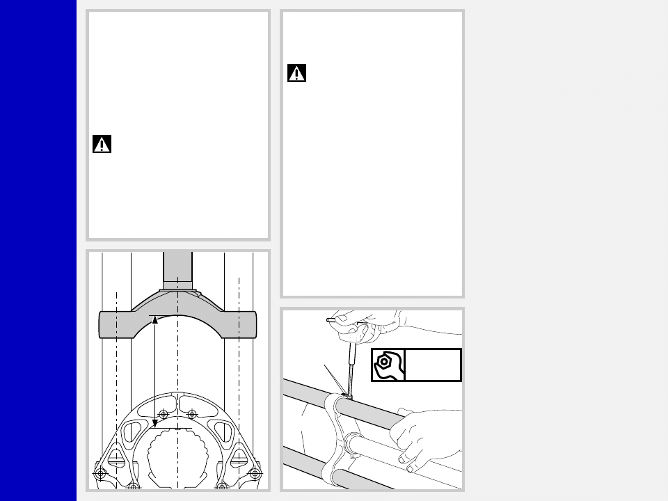
MOUNTING THE FORK ON THE
FRAME
FIG. A
Remove the upper plate (28) from steer
tube and fork legs by loosening the 3
fastening bolts (27).
28
27
Q
R
2
0
Mr. T
FIG. B
Assemble the fork to the frame complete
with headset. Fit the upper plate (28) into
the stanchions and the steer tube.
28
FIG. C
The stanchions edge (13) must be aligned
with or slightly lower than the upper plate
(28).
If fork legs overprotrude, fit some spacers
(C) to the plate close to the steer tube.
C
28
13
FIG. D
Fit the handlebar support and the A-Head
Set cap over the upper plate (28) and then
adjust the steering.
Now finally tighten the 3 bolts (27) on the
upper plate to 11 Nm.
IMPORTANT: Loosen the 3 screws
(27) on the upper plate before
adjusting the steering. Tighten the above
bolts to the specified torque when fin-
ished.
27
Nm
11
Q
R
2
0
Mr. T
FIG. F
Tighten the 4 stanchions fastening screws
(26) onto the crown to 11 Nm.
WARNING: do not overtighten
the screws holding the stanchions
to the crown as this may distort the stan-
chion tubes and weaken the whole struc-
ture.
After any installation always check for the
following:
– proper torque of bolts fastening stan-
chion tubes onto crown and upper
plate;
– proper torque of bolts fastening brake
arch onto slider (11 Nm).
26
13
Nm
11
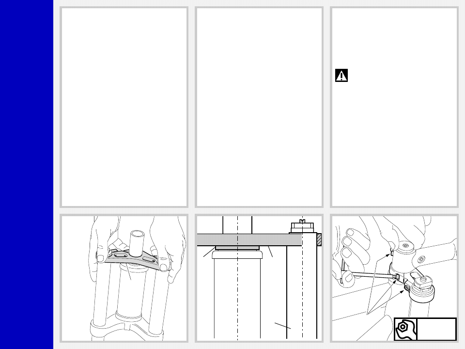
FIG. E
If the crown (33) position with respect to
the stanchion tubes (13) has been changed
for any reason, adjust the original dis-
tance.
– Distance “H” between crown and tyre
edge (when inflated) should not be
lower than total travel (140 mm) + 3
mm.
WARNING: if steering crown is
improperly matched with stan-
chions, it may touch the tyre and cause
severe injuries to the rider.
H
Q
R
2
0
Mr. T
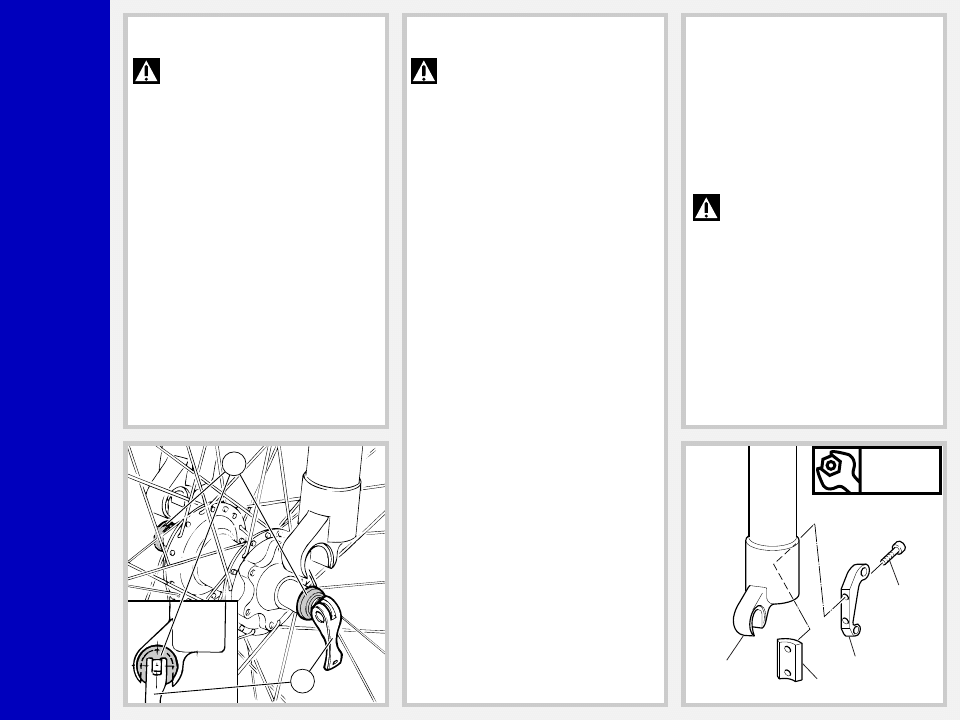
DISC BRAKE SYSTEM ASSEMBLY
(Fig. H)
Assembling the brake caliper onto the
slider is a very delicate operation that
should be carried out with extreme care.
Improper assembly might overstress the
caliper supports, which might break.
Screw the caliper support (34) to the slider
(20) using the screws (35) and plate (33).
IMPORTANT: Clean the mating
surfaces inside and outside slider,
otherwise dirt may affect caliper position
or cause the screws (35) to become loose.
Tighten the screws (35) to 9 Nm.
When installing the disc brake system, be
sure to properly follow the instructions
given by the manufacturer.
Nm
9
20
33
35
34
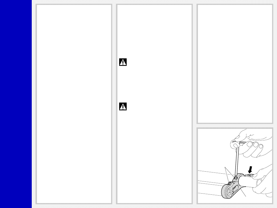
FRONT WHEEL ASSEMBLY (Fig. G)
IMPORTANT: fixing the front
wheel properly as specified in the
instructions given below is essential for the
proper operation of this fork and all re-
lated devices, and therefore for safe rid-
ing. You are advised to follow these
instructions closely.
Slacken the lock nut of the quick release
lever so the hub will fit between the fork
sliders.
Make sure the quick release bushings (E)
are centered to the recesses in the sliders.
Lock the quick release lever (F) and make
sure the bushings (E) are properly seated
in the sliders.
E
F
WARNING: These sliders are spe-
cifically designed to fit this type of
hub. Do not use any hub design other than
that specified here, as this would not
ensure proper fastening of the wheel and
may lead to breakdown of the assembly
components.
Q
R
2
0
Mr. T
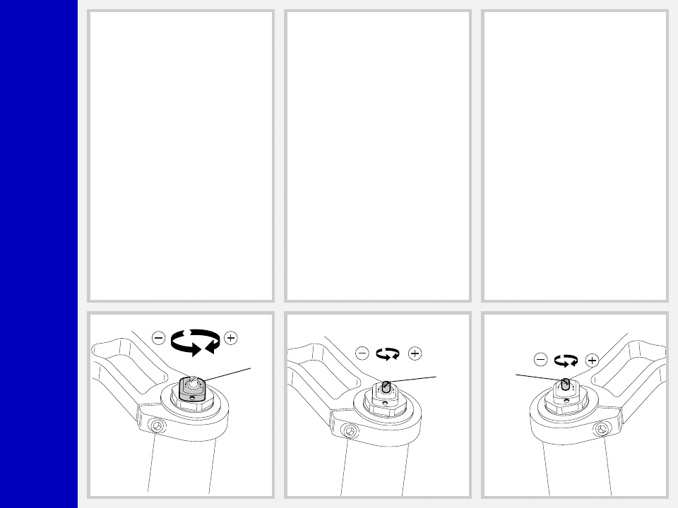
REBOUND DAMPING ADJUSTMENT
(Fig. M)
The r.h. fork leg features an adjuster (D)
for REBOUND damping adjustment. Ad-
justment and setting range are the same
as for the compression damping adjuster
(C) above.
D
ADJUSTMENTS
SPRING PRELOAD (Fig. I)
The spring preload for COMPRESSION
damping can be adjusted by turning the
knob (2) on top of fork legs. From the
factory the Mr. T is set with the minimum
preload, i.e. the adjustment knob is com-
pletely unscrewed counterclockwise. How-
ever, the springs are slightly preloaded to
help counteract static loads. By turning the
adjustment knob clockwise, the preload is
increased up to the maximum value equal
to 15 mm of spring preload. This adjust-
ment is essential in order to have the right
Mr. T response for the rider weight and
riding style.
COMPRESSION DAMPING
ADJUSTMENT (Fig. L)
The l.h. fork leg is equipped with an
adjuster (C, BLACK) for COMPRESSION
damping adjustment. Turning this adjuster
clockwise into the cartridge rod, changes
the hydraulic setting of the inner valves. In
short, the amount of adjustment applied
on the piston in the fluid determines the
rate of compression damping.
To adjust, always start from the minimum
damping setting, i.e. unscrew completely
counterclockwise. About 8 turns - abt. 4
mm of the adjustment - are possible.
2
C

Q
R
2
0
Mr. T
▲
▲
▲
▲
▲
▲
▲
▲
▲
▲
▲
▲
▲
▲
▲
▲
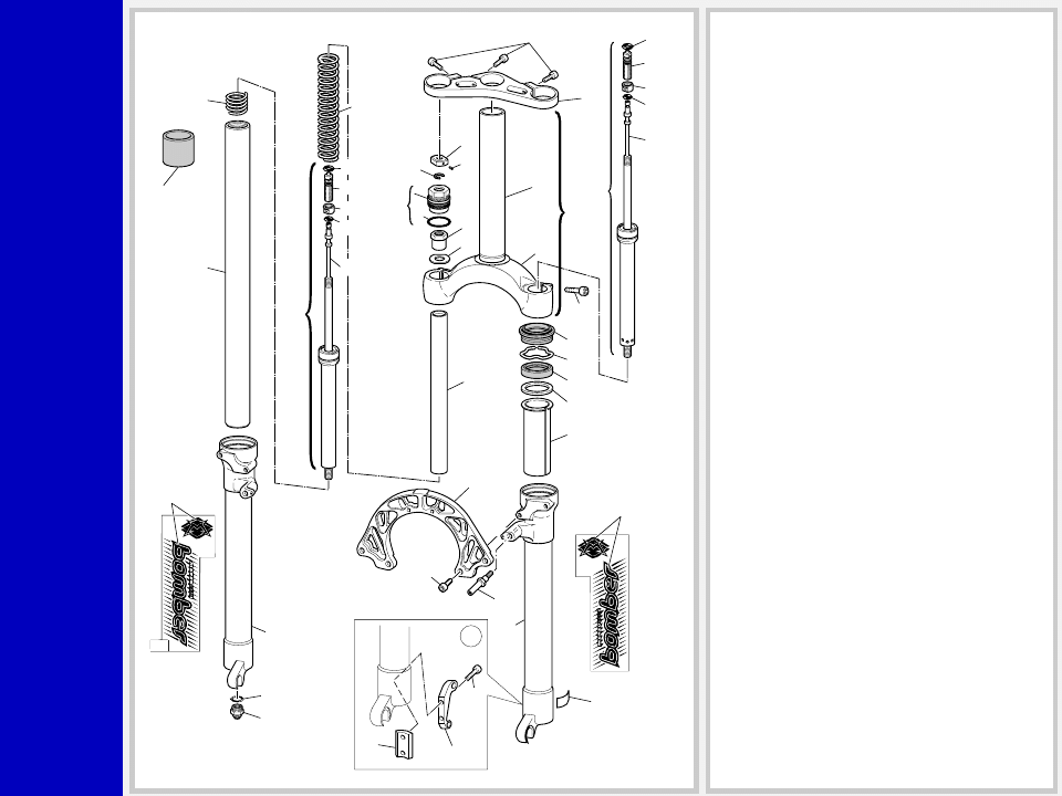
DISASSEMBLY
GENERAL
– The reference numbers given in this section relate to the components shown in the fork exploded view.
– Operations refer to the fork legs already removed from the upper plate and from the crown and disassembled from the brake arch.
– Before starting any operation. please read the diagram below. It shows the quickest procedure and the exact disassembling
sequence. Start from the part to be disassembled and then follow the arrows to remove the other parts.
DISASSEMBLY DIAGRAM
STOP RING FIG. 2
STANCHION TUBE FIG. 7
DUST SEAL FIG. 8
SPRING FIG. 4
PRELOAD KNOB FIG. 1
HYDRAULIC CARTRIDGE
CHANGE
FOOT NUT FIG. 5
HYDRAULIC CARTRIDGE FIG. 6
GUIDE BUSHING AND SEAL
ASSEMBLY CHANGE
OIL SEAL FIG. 10
UPPER WASHER FIG. 11
GUIDE BUSHING FIG. 12
STANCHION TUBE CAP FIG. 3
SPRING CHANGE
STOP RING FIG. 9
FORK OIL CHANGE
REBOUND SPRING FIG. 6
Q
R
2
0
Mr. T
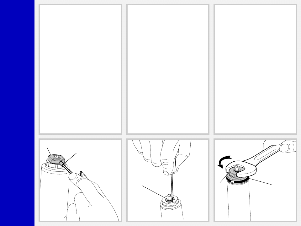
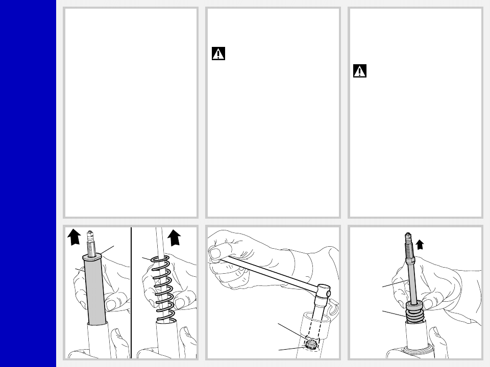
SPRING CHANGE
FIG. 1
Set the knob (2) to the minimum preload
position.
Loosen the grub screw (3) fastening the
preload knob (2) by means of a 1.5 mm
Allen wrench. Remove grub screw from
cap assembly.
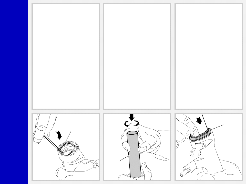
FIG. 2
Remove the stop ring (4) from the top of the
preload knob support with a small screw-
driver.
FIG. 3
Place the stanchion tube in a vice making
sure not to damage or dent it in the
process and unscrew the cap (5) with a 26
mm open end wrench.
Remove the cap complete with O-ring (6)
from the stanchion tube.
2
3
4
5
6
Q
R
2
0
Mr. T
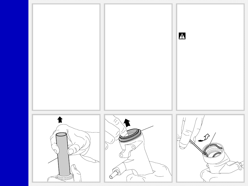
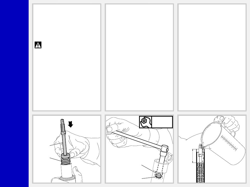
FIG. 4
Push the stanchion tube into the slider and
remove the lower washer (8), the preload
sleeve (1) and the spring (9).
Let all the oil drain into the fork leg. By
following this procedure, there is no need
to check the oil level. Make all necessary
changes.
9
1
8
22
21
11-29
12
HYDRAULIC CARTRIDGE CHANGE
FIG. 5
Let all the oil drain out.
WARNING: Remember to always
recycle any used oil.
To change the fork leg oil follow the
procedure as described in section
“REASSEMBLY” from FIG. 21 to FIG. 26.
Turn the fork leg upside-down and un-
screw the foot nut (22) complete with O-
ring (21) by the use of a 15 mm socket
wrench.
FIG. 6
Pull the hydraulic cartridge (11 or 29)
complete with rebound spring (12) out of
the stanchion tube.
Replace the whole hydraulic cartridge.
IMPORTANT: The hydraulic car-
tridge accommodated in the l.h.
fork leg controls COMPRESSION damp-
ing. You can tell it from the rebound
cartridge by the BLACK inner rod and the
holes in cartridge casing.
Q
R
2
0
Mr. T
GUIDE BUSHING AND SEAL
ASSEMBLY CHANGE
FIG. 7
Pull the stanchion tube (13) completely out
of the slider.
13
14
15
FIG. 8
Use a small screwdriver and remove the
dust seal (14) from slider top.
FIG. 9
Remove the stop ring (15) from the slider
by placing the screwdriver bit in one of the
three openings on the stop ring and care-
fully lifting the ring out of place.
IMPORTANT: when removing the
stop ring, make sure not to damage
its seat.
Q
R
2
0
Mr. T
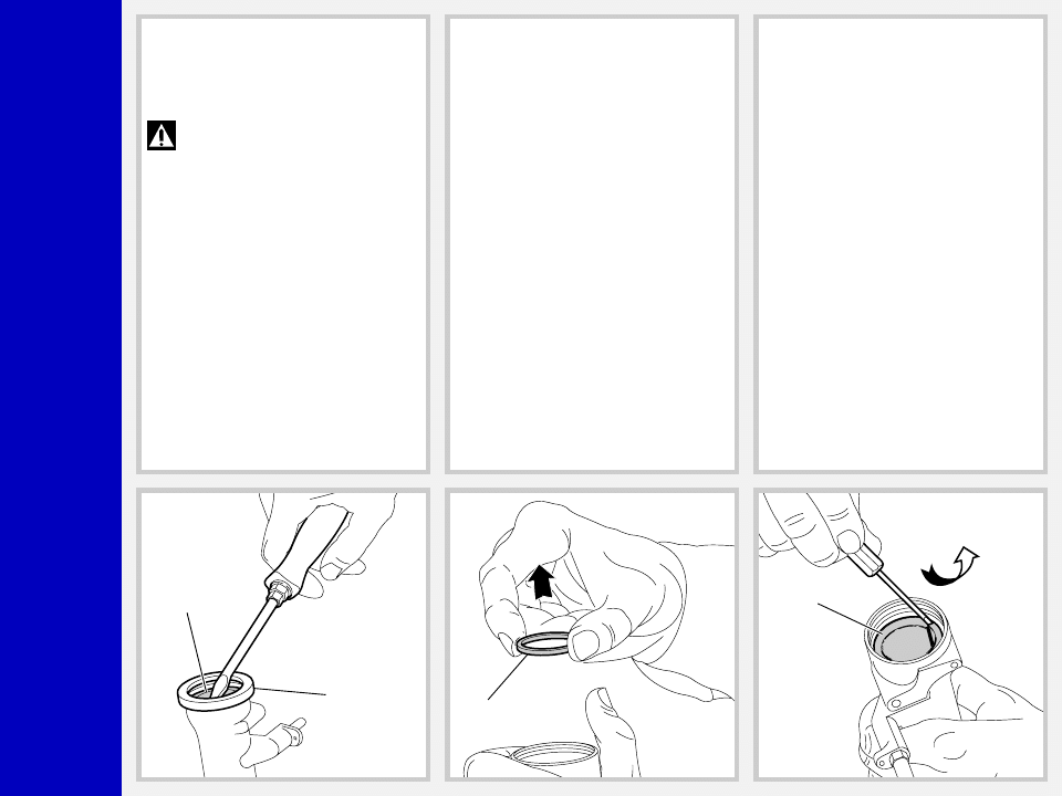
FIG. 10
Fit the slider protector (A) onto the slider
and remove the oil seal (16) with the help
of a large slot screwdriver.
IMPORTANT: when removing the
oil seal, make sure not to damage
its seat. Once removed the oil seals should
not be used again.
16
A
17
FIG. 11
Remove the upper washer (17) from the
slider.
FIG. 12
Fit the bit of a small screwdriver into the
upper edge slot of the guide bushing (18)
and lift gently. Pull the bushing out of the
slider and make all necessary changes.
18
Q
R
2
0
Mr. T
REASSEMBLY
CAUTION: before reassembling,
all metal components should be
washed carefully with inflammable and
biodegradable solvent and dried with
compressed air.
GUIDE BUSHING AND SEAL
ASSEMBLY
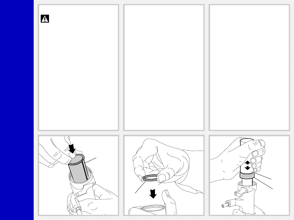
FIG. 13
Check that no dirt or debris is between
slider and bushing. Insert the guide bush-
ing (18) into place so that it adheres to the
slider.
18
17
16
B
FIG. 14
Fit the upper washer (17) into the slider so
that it touches the guide bushing.
FIG. 15
Lubricate the oil seal (16) and place it onto
the seal press (B) with the hollow side
toward the slider.
Press the oil seal into place until it touches
the lower washer by using the above seal
press.
Q
R
2
0
Mr. T
FIG. 16
Insert the stop ring (15) making sure it is
properly seated into place in the slider.
15
13
14
STANCHION TUBE
FIG. 17
Fit the stanchion tube (13) gently into the
dust seal (16), from the non threaded end.
Rotate the stanchion tube while inserting it
into the seal to facilitate installation and
reduce the chance of damaging the seals.
Check to see that the stanchion tube slides
unrestricted by cycling the fork up and
down several times. The tube should slide
freely inside the seal assembly without
any side play. In the event it is too hard or
too soft, repeat the previous steps de-
scribed above and check components to
ensure they are not damaged.
FIG. 18
Lubricate the dust seal (14) and fit it into its
seat in the stanchion.
Q
R
2
0
Mr. T
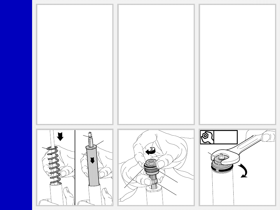
HYDRAULIC CARTRIDGE
FIG. 19
Fit the rebound spring (12) into the hy-
draulic cartridge. Insert the complete hy-
draulic cartridge (11 or 29) with the
stanchion pressed fully down into the
slider.
IMPORTANT: The cartridge with
the BLACK inner rod goes into the
l.h. fork leg.
11-29
12
22
21
Nm
12
95
FIG. 20
Grease the O-ring (21) on the foot nut (22)
and screw the nut on the hydraulic car-
tridge threaded end.
Tighten to 12 Nm.
Pump stanchion up and down several
times to make sure it slides properly through
the stroke.
HOW TO FILL WITH OIL
FIG. 21
Pour the oil little by little when the stan-
chion tube is fully down and then pump
with the cartridge (11 or 29) rod so as to
have a better filling. Cartridge is full when
no air is detected when pumping, in the
fully compressed position. Check that the
oil level is 95 mm/3.74 in. from the top of
the stanchion tube in each leg.
Q
R
2
0
Mr. T
SPRING AND CAP
FIG. 22
Fit the spring (9), the preload sleeve (1)
and the top washer (8) into the stanchion
tube.
Lubricate the O-ring (10) on the top of the
preload knob support and the O-ring (6)
on the cap (5).
9
1
8
10
5
6
11-29
5
Nm
12
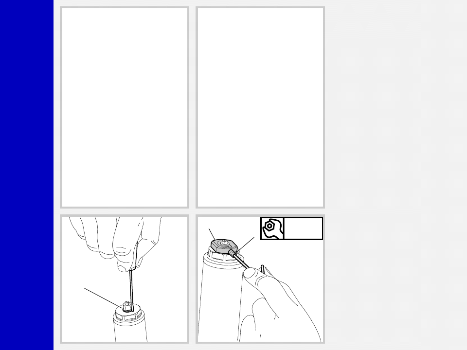
FIG. 23
Move the plunger (7), in the cap, to the
minimum preload position.
Screw the complete cap (5) onto the
cartridge (11 or 29) rod. Screw cap all the
way in.
FIG. 24
Take the stanchion tube and fit the cap (5)
by hand. Place the stanchion tube in a vice
making sure it is not damaged or dented
in the process and tighten the cap to 12
Nm.
Q
R
2
0
Mr. T
FIG. 25
Fit the stop ring (4) of the preload knob
support and make sure it is properly
seated into place.
4
FIG. 26
Fit the preload knob (2) and secure it on
the support by tightening the grub screw
(3) to 1.5 Nm.
Fit the brake arch to the fork leg, and then
install fork legs into crown and upper
plate as specified in section “INSTALLA-
TION”.
Nm
1,5
2
3
Q
R
2
0
Mr. T
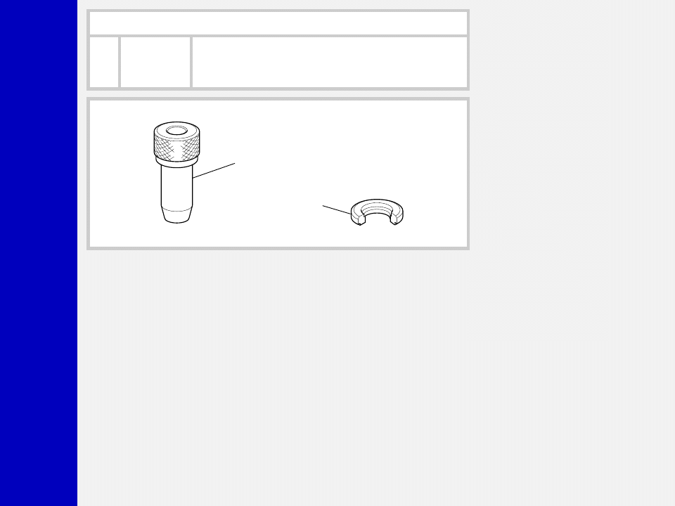
SPECIFIC TOOLS
Ref.
Item.
Description and use
A
536003 AB
Slider protector: to remove the oil seal from the slider
B
R 5068
Oil seal press: to press oil seal into the slider
A
B
Wyszukiwarka
Podobne podstrony:
2000 z2 x fly qr20 service manual
Beomaster 2000 int Service Manual
Inter MR 150 300 500 pwr Service Manual
Service Manual NEC Versa 2000 Series Laptop
2000 monster t service manual
Jvc VSDT 2000 Service Manual
Beomaster 2000 int Service Manual
hplj 5p 6p service manual vhnlwmi5rxab6ao6bivsrdhllvztpnnomgxi2ma vhnlwmi5rxab6ao6bivsrdhllvztpnnomg
Oberheim Prommer Service Manual
Korg SQ 10 Service Manual
MAC1500 service manual
Kyocera Universal Feeder UF 1 Service Manual
Proview RA783 LCD Service Manual
indesit witp82euy Service Manual
Glow Worm installation and service manual Hideaway 70CF UIS
Proview PZ456 LCD Service Manual
Glow Worm installation and service manual Ultimate 50CF UIS
więcej podobnych podstron