
Subject
Page
E85 Heating / Air Conditioning System............................................... 3
IHKS Components.................................................................................3
IHKS Principle of Operation................................................................... 8
IHKA Components............................................................................... 11
IHKA Principle of Operation..................................................................21
Workshop Hints....................................................................................27
Review Questions.................................................................................31
Table of Contents
E85 Heating / Air Conditioning System

2
E85 Heating/Air Conditioning System
E85 Heating / Air Conditioning System
Model: E85
Production: Start of Production MY 2003
Objectives:
After completion of this module you will be able to:
• List the “visual” differences that identify IHKA from IHKS.
• Explain how are 3 sets of distribution flaps controlled by one stepper motor on the IHKS
system.
• Access the microfilter for service.
• Diagnose a faulted interior temperature sensor blower (IHKA).
• Describe what occurs with the A/C compressor when MAX AC is switched off (IHKA).
• Understand how to deactivate Transportation Mode before vehicle delivery.

3
E85 Heating/Air Conditioning System
E85 Heating / Air Conditioning System
Purpose of the System
This module describes the heating and air conditioning systems of the Z4. A differentiation
is made between (depending on how the vehicle is equipped):
• Integrated heating and air conditioning control - IHKS
• Integrated automatic heating and climate control - IHKA
Compared to the predecessor (Z3), the optional IHKA including automatic recirculating air
control AUC is a unique feature in the roadster.
In both variants, the control panel consists of three control zones each with a rotary knob.
These are elevated from the instrument panel like "islands" to underscore the sporty char-
acteristics and enhance the high grade appearance of the roadster. The rotary knobs fea-
ture precision adjustment and rotary function lighting.
Various function buttons that differ depending on IHKS/IHKA are integrated in the center
"island."
Advantages at a glance:
• Sporty and high grade control panel appearance.
• The island design provides clearly arranged and easy to use controls.
• Precision adjustment for air distribution, blower speed and temperature setting.
• Common parts concept implemented to a large extent.
• No water shut-off valve and auxiliary water pump due to airbased control.
IHKS System Components
The IHKS system consists of following components:
• IHKS control panel/control module
• IHKS heater/air conditioner unit
• Refrigerant pressure sensor
• Evaporator temperature sensor
• A/C compressor
• Rear window defogger relay
4
E85 Heating/Air Conditioning System
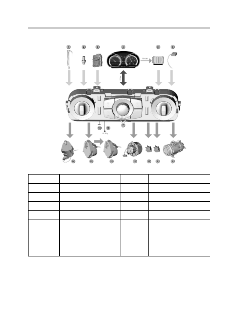
System Overview of IHKS Input/Output Signals
The variations of the IHKS system as compared to the IHKA are described in the following
pages. IHKA is detailed later in this module.
Index
Explanation
Index
Explanation
1
Evaporator temperature sensor
9
Relay 1, rear window defogger
2
Refrigerant pressure sensor
10
Relay 2, rear window defogger
3
Fuse holder with terminal 30, R and 15
11
Blower output final stage and blower
4
Instrument Cluster
12
Stepper Motor, Mixed Air Flap
5
ECM (DME) Input signal
13
Stepper Motor, Air Distribution
6
Microswitch, cam disc
14
Actuator, Fresh air/recirculation air flap
7
IHKS Control Panel / Control Module
15
Ground (terminal 31)
8
Magnetic clutch for A/C compressor
16
Terminal 58g instrument lighting
5
E85 Heating/Air Conditioning System
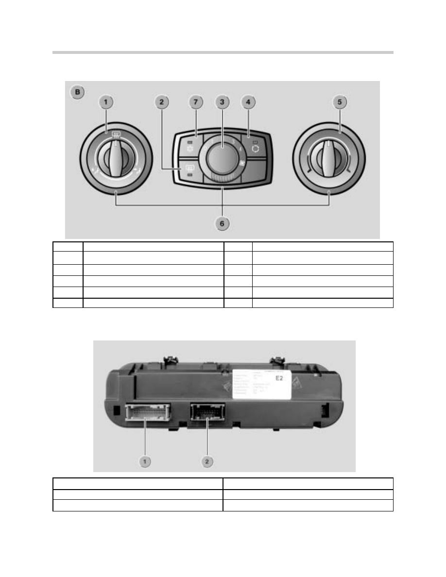
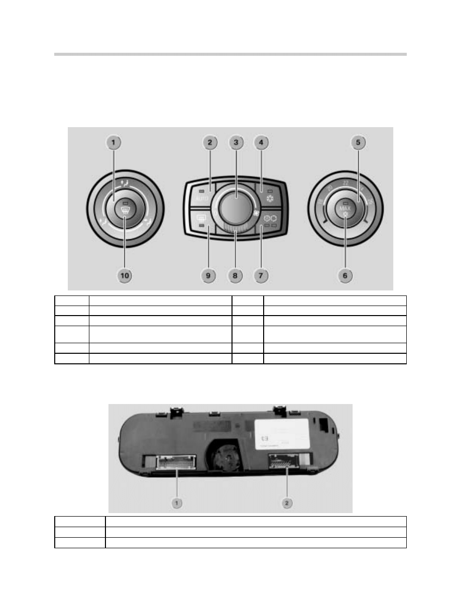
IHKS Control Panel/Control Module
Index
Explanation
Index
Explanation
1
Rotary knob, air distribution
6
Trim rings (fitted from front)
2
Button, rear window defogger
7
A/C button
3
Rotary knob, blower setting
4
Recirculating air button
5
Rotary knob, temperature setting
B
IHKS Control Panel/Control Module
Plug connection, rear of IHKS Control Panel/Control Module
Index
Explanation
1
24-pin plug connection, vehicle electrical system
2
18-pin plug connection, heater/air conditioner
6
E85 Heating/Air Conditioning System
The rotary knob for air distribution (adjustment range of 360º rotation) features 3 rough set-
tings and 9 fine settings.
The rotary knob for blower control (adjustment range of 104º rotation) provides the follow-
ing setting options:
• 1 rough setting for zero position
• 8 fine settings for the 4 blower stages each with one intermediate stage
The rotary knob for temperature control (adjustment range of 244º rotation) provides the fol-
lowing setting options:
• 23 fine settings over the complete adjustment range from cold to warm.
Note: The rotary function light and the vehicle interior temperature sensor are features of
the IHKA only.
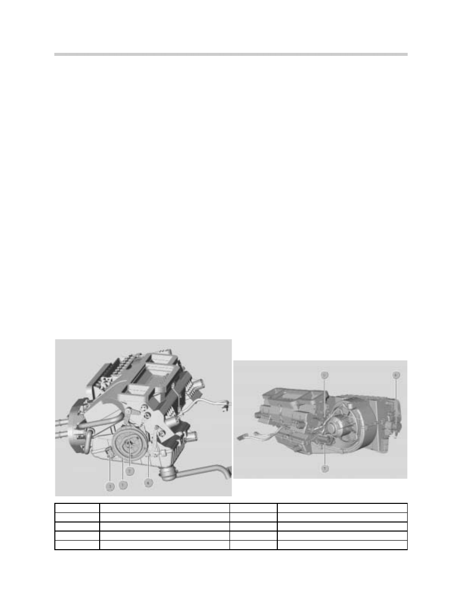
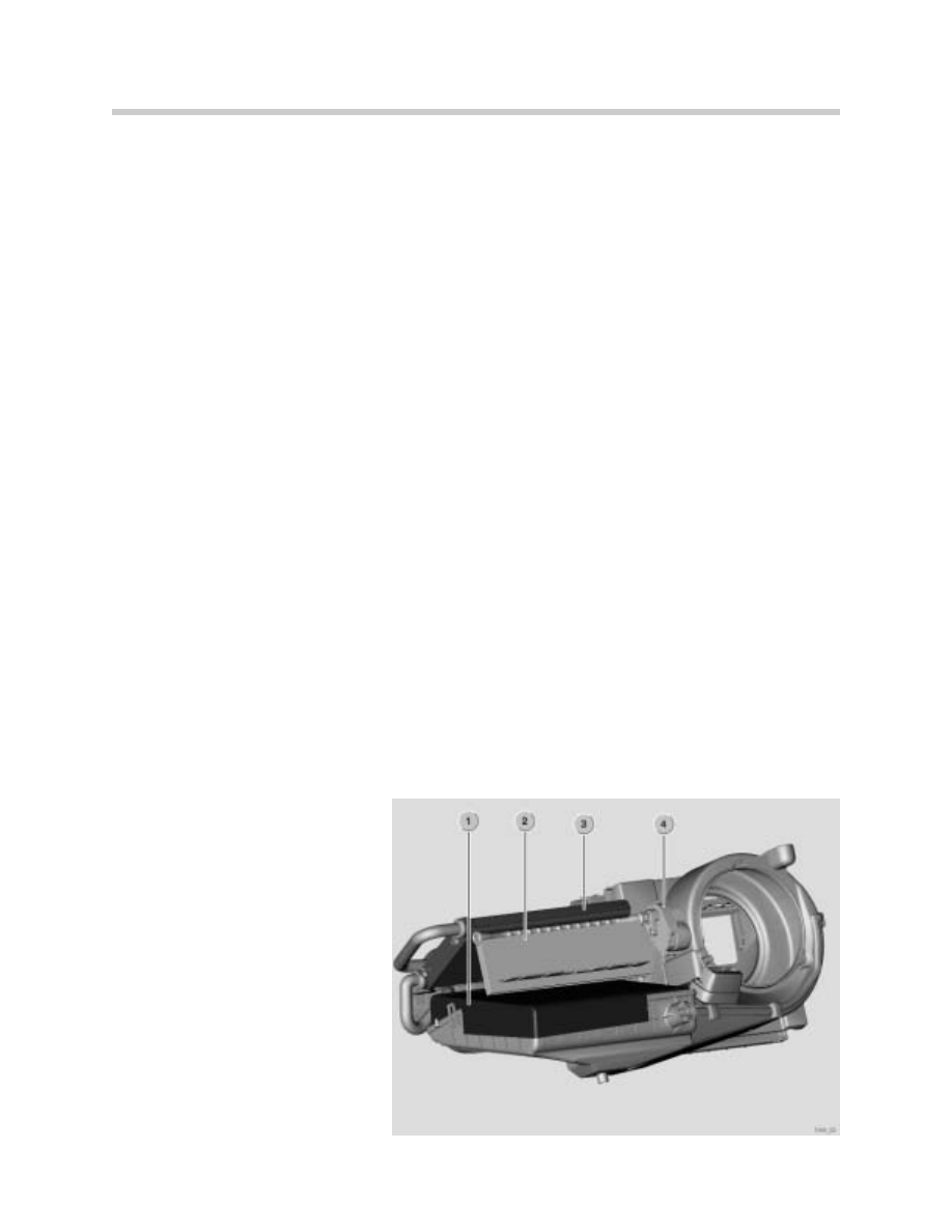
IHKS Heater/Air Conditioner
The following components are integrated in the IHKS heater/air conditioner unit:
• Actuator, fresh air/recirculating air flap
• Stepper motor, mixed air flap
• Stepper motor, air distribution
• Cam disc with microswitch
• Blower output final stage and blower motor
• Evaporator temperature sensor
Index
Explanation
Index
Explanation
1
Cam disc
5
Stepper, motor, mixed air flap
2
Stepper motor, air distribution
6
Actuator, fresh air/Recirculation air flap
3
Microswitch
7
Blower output final stage
4
Evaporator temperature sensor
7
E85 Heating/Air Conditioning System
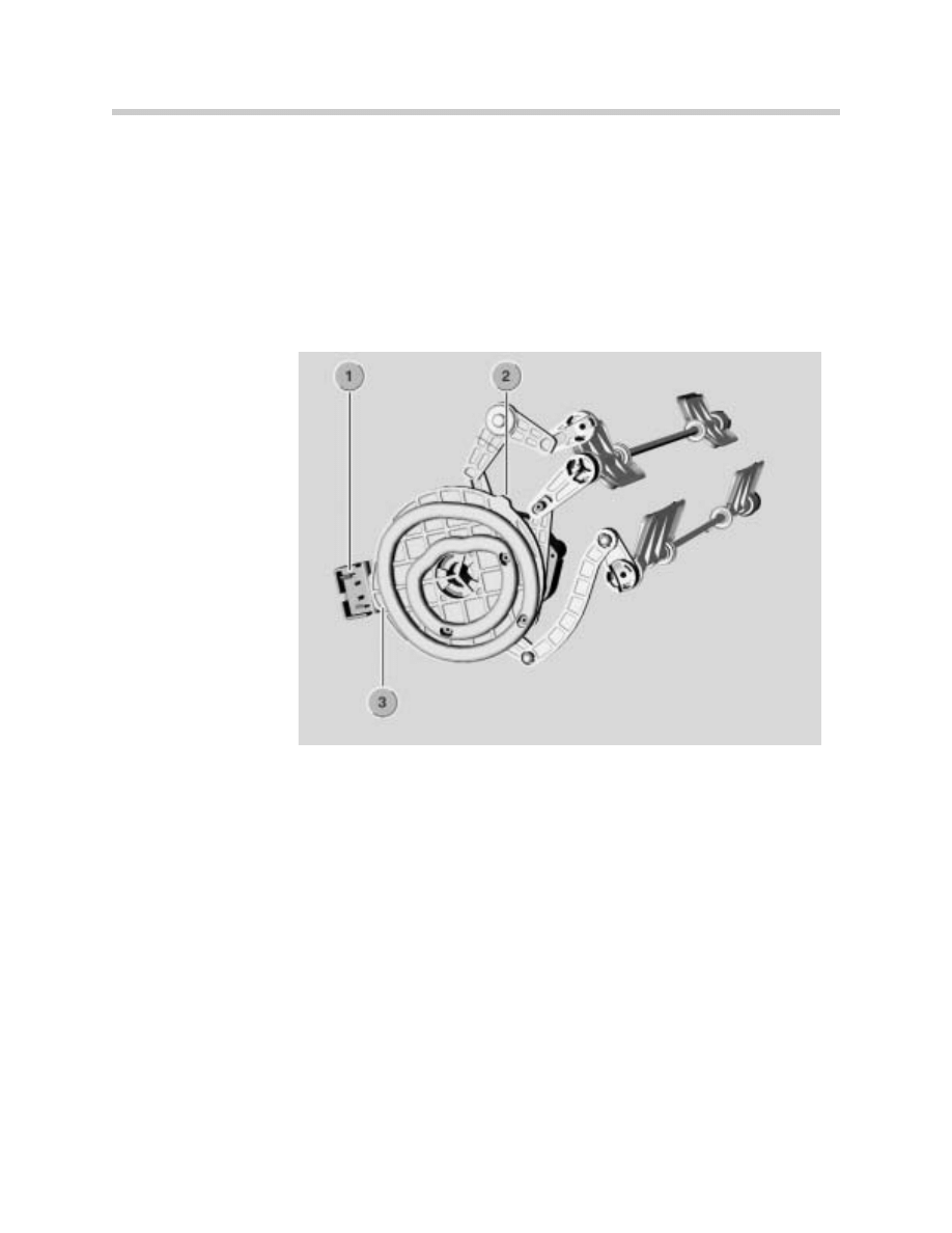
The stepper motor for the air distribution and for adjusting the 3 air distribution flaps is
mounted directly behind the cam disc. The Control module activates the stepper motor
(corresponding to the required position) when the rotary control for air distribution is oper-
ated.
The cam disc moves the air distribution flaps by “central kinematics”. The actual position of
the cam disc and stepper motor is detected by 2 small cams of different width that activate
a microswitch. This microswitch provides feedback to the IHKS Control Module which cor-
responds to the air distribution flaps and their positions.
1. Microswitch
2. Narrow cam
3. Wide cam
After KL15 is switched “OFF” and a sleep mode of 10 minutes, the flaps are moved to the
following end positions:
• Defrost flap dependent on outside temperature
> 10 ºC CLOSED (50 ºF),
< 10 ºC OPEN (50 ºF)
• Ventilation flap CLOSED
• Footwell flap CLOSED
A calibration run is carried out in the event of a system fault (e.g. implausible position of cam
disc) to redetermine the position of the cam disc. The cam disc is moved until a cam trips
the microswitch. Based on this position, a set position is specified and set in the control
module.
8
E85 Heating/Air Conditioning System
A cam measurement (reference run) takes place the first time the control panel/control
module is operated after:
• Replacing the control panel/control module
• Replacing the cam disc
• Interruption in power supply
During this reference run, the length and distances of both cams with respect to each other
are measured and stored in the control module. A fault code is stored if cam referencing
cannot be concluded successfully after 3 attempts. In this case, adjustment of the central
kinematics for air distribution is possible only within restricted limits.
IHKS Principle of Operation
Blower
When KL15 is switched “ON”, the blower is activated in linear progression from 0 to 8 Volts
(depending on the selected blower speed). When the blower is switched “OFF” (zero posi-
tion) the IHKS is deactivated in addition to the following:
• Blower switched off
• Fresh air/recirculating air flap closed
• Mixed air flap closed (to ensure the heat exchanger does not unnecessarily heat up the
heater/air conditioner)
• Compressor switched off
Note: Rear window defogger can still be activated
Temperature Control
1. Evaporator
2. Mixed air flap
3. Heat exchanger
4. Stepper motor, mixed air flap
9
E85 Heating/Air Conditioning System
Warm and cold air are mixed for temperature control. The requested temperature is set by
the rotary knob on the control panel/control unit. The outlet temperature is set by a step-
per motor coupled to the mixed air flap.
The temperature is controlled by mixing:
• Outside air that flows through the evaporator = cold air
• Outside air that initially flows through the evaporator and then through the heat exchang-
er (reheat) = warm air
Note: Changes in engine rpm do not trigger any temperature adjustments.
Air Distribution
The individual setting for the air distribution is requested with the rotary knob on the con-
trol panel. The main flap settings are:
"Defrost"
"Ventilation"
"Footwell"
The central kinematics stepper motor adjusts the cam disc for air distribution.
Notes:

10
E85 Heating/Air Conditioning System
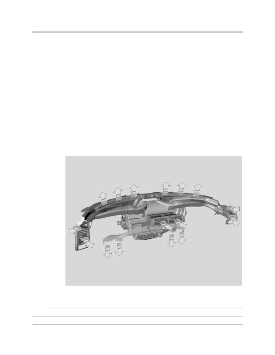
Air Volume Control
The air volume is controlled based on the position of the fresh air/recirculating air flap and
blower speed. There is 1 flap at the fresh air inlet and 2 flaps for recirculating air control.
The actuator for the fresh air/recirculating air flap adjusts these 3 individual flaps by a cou-
pling linkage.
The system assumes recirculating air mode after pressing the recirculating air button. The
fresh air inlet is closed and the recirculating air channel opened. The actuator for the fresh
air/recirculating air flap is not a stepper motor. Its position is determined based on the acti-
vation of 4 phases.
Notes:
11
E85 Heating/Air Conditioning System
IHKA
Compared to the IHKS, the integrated automatic heating and climate control (IHKA) offers
the advantage of automatic adaptation for:
• Air volume control
• Temperature control
• Air distribution control
These control functions are calculated by the IHKA control module from the inputs, char-
acteristic curves and monitored via temperature sensors. The IHKA in the E85 differs from
the previous BMW systems (digital displays) in that it features an analogue control panel.
Special functions such as Defrost, Fresh air/AUC/recirculating air etc. are also controlled by
the IHKA control module. The IHKA control panel and control module form one component.
IHKA System Components
The IHKA consists of following components:
• Control panel/control module
• Heater/air conditioner unit
• AUC sensor
• A/C compressor
• Refrigerant pressure sensor
• Rear window defogger relay
Note: The solar sensor is not available on the E85 IHKA system.
12
E85 Heating/Air Conditioning System
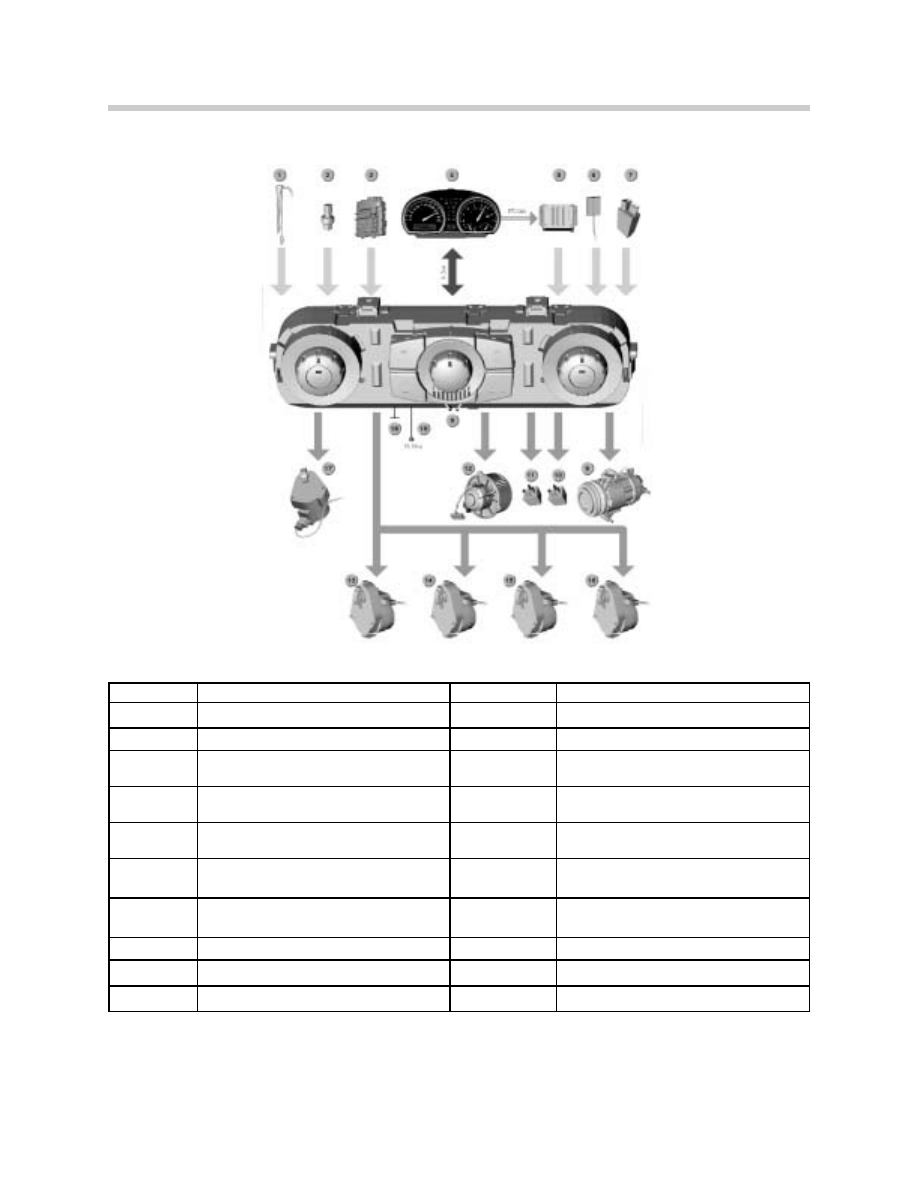
System Overview of IHKA Input/Output Signals
Index
Explanation
Index
Explanation
1
Evaporator temperature Sensor
11
Relay 2, Rear Window Defogger
2
Refrigerant pressure sensor
12
Blower Output Final Stage and Blower
3
Power Distribution Box with Terminal 30,
R and 15
13
Stepper Motor, Mixed Air Flap
4
Instrument Cluster
14
Stepper Motor, Air Distribution, top
(defrost)
5
Digital Motor Electronics (ECM)
15
Stepper Motor, Air Distribution Center
(ventilation)
6
Temperature Sensor, Mixed Air
16
Stepper Motor, Air Distribution, bottom
(footwell)
7
AUC Sensor (Automatic Recirculation
Air Control)
17
Actuator, fresh air/recirculation air flap
8
IHKA Control Panel/Control Module
18
Ground
9
Magnetic Clutch, A/C Compressor
19
Terminal 58g Instrument Lighting
10
Relay 1, Rear Window Defogger
13
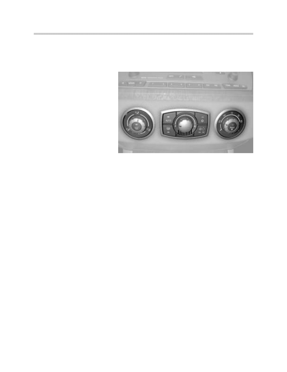
E85 Heating/Air Conditioning System
IHKA Control Panel/Control Module
The IHKA control panel/control module is one component and is located in the center of
the instrument panel under the radio/navigation control panel (above the center console
switch center).
Index
Explanation
Index
Explanation
1
Rotary Knob, Air Distribution
6
MAX AC Button
2
AUTO Button
7
AUC/Recirculation Air Button
3
Rotary Knob, Blower Setting
8
Opening For Ventilated Interior Temperature
Sensor
4
A/C Button
9
Rear Window Defogger Button
5
Rotary Knob, Temperature Setting
10
Defrost Button
Index
Explanation
1.
24-Pin Plug Connection to Vehicle Electrical System
2.
18-Pin Plug Connection to Heater/Air Conditioning
Plug connection, rear of IHKA Control Panel/Control Module

14
E85 Heating/Air Conditioning System
The 3 control elements of the control panel/control unit are enclosed by trim rings. These
trim rings are clipped into the instrument panel from the front and can be replaced sepa-
rately.
The rotary knob for air distribution (adjustment range of 360º rotation) features 3 main set-
tings and 10 precision settings in between.
The rotary knob for blower speed (adjustment range of 180º rotation) features 1 main notch
for the zero setting. There are 14 precision settings from the zero position up to the maxi-
mum setting.
The rotary knob for temperature setting (adjustment range of 240º rotation) has 2 main set-
tings (maximum cold/maximum warm) with 23 precision settings in between. Temperature
setting range:
• Maximum cold (corresponds to 60 ºF)
• Individual temperature setting range (in steps of 1 ºF)
• Maximum warm (corresponds to 84 ºF)
The following buttons feature a green function light (LED): AUTO, A/C, MAX AC. The but-
ton for AUC/recirculating air has 2 green function lights (LEDs).
The rear window defogger and defrost buttons feature an orange colored function light
(LED). When the vehicle lights are switched on, the indicator lights are activated via termi-
nal 58g. The signal comes from the light switch center (LSZ).
The locator lights and function lights are dimmed corresponding to the dimmer control
wheel position on the light switch center and/or depending on the ambient light conditions
(photocell in light switch center).
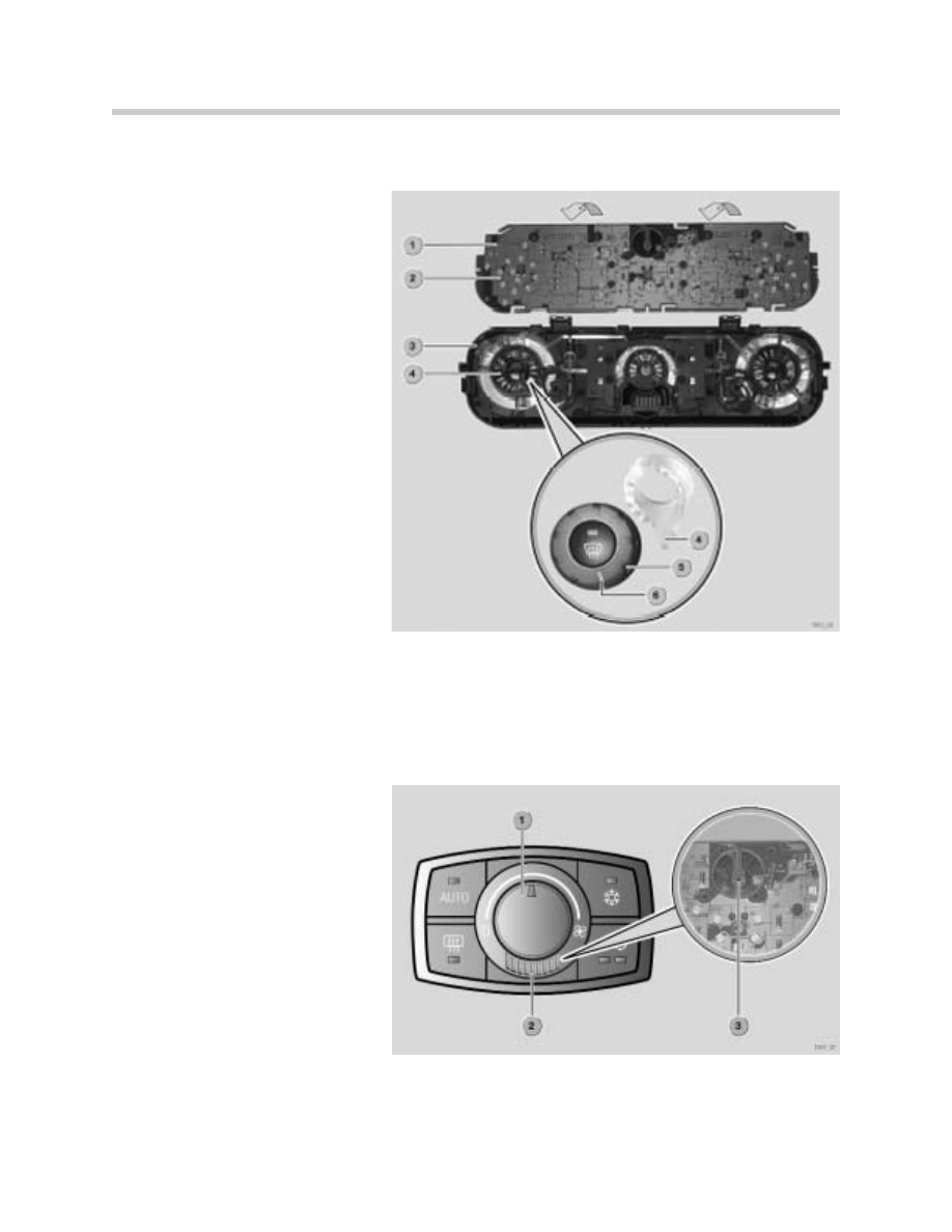
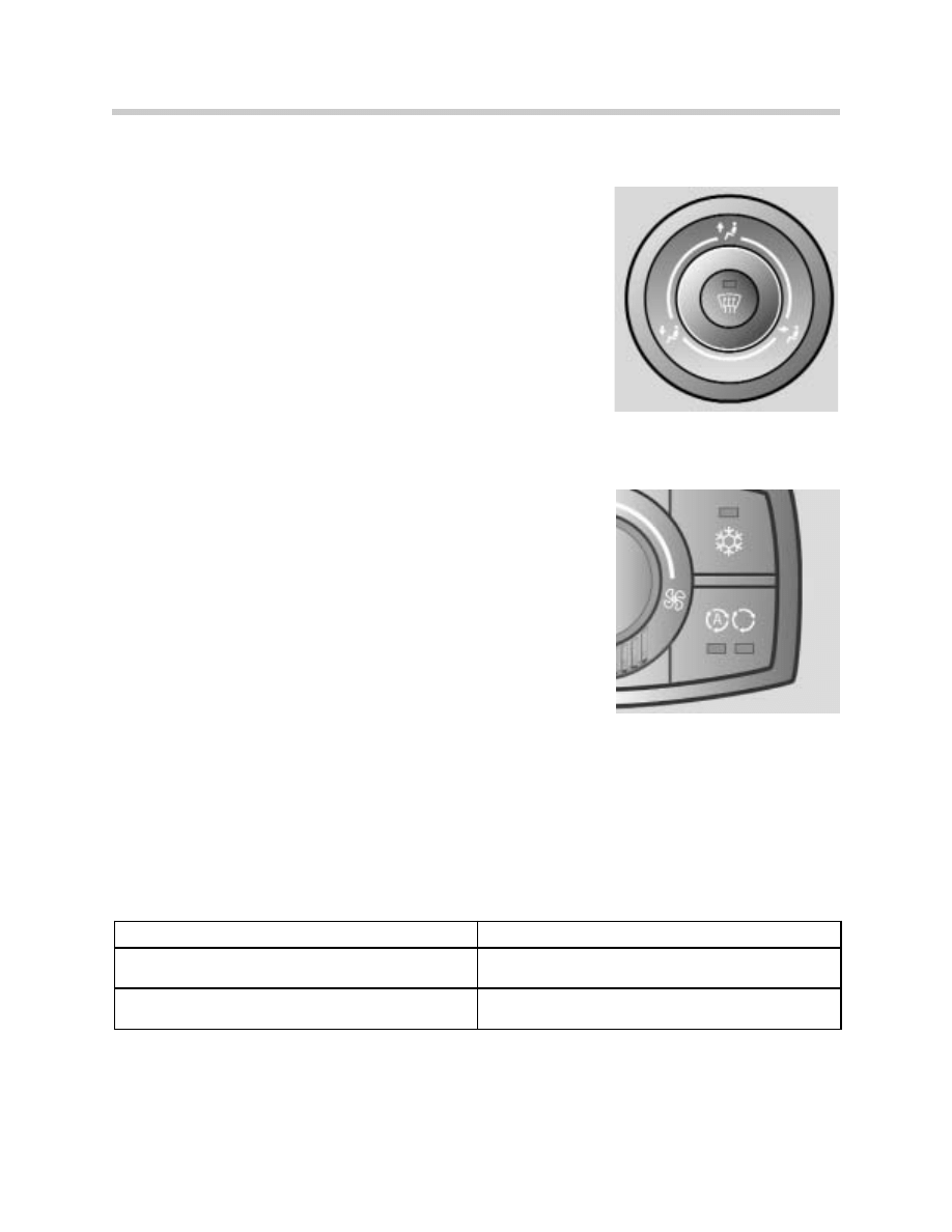
Rotating function light
A special feature of the IHKA is the rotary function light in all three knobs. For example; the
rotary knob for air distribution has an adjustment range of 360º rotation. 8 LEDs are locat-
ed on the pc-board (under the knob) at its circumference to ensure it can be seen clearly
from different viewing directions.
A light element is located in the rotary knob (connected mechanically) and turns together
with it.
15
E85 Heating/Air Conditioning System
The light element functions as a light guide. It bundles the light of the LEDs and, due to its
geometrical shape, guides it to the light outlet window of the rotary knob.
This ensures the full light intensity
is always emitted at the light out-
let window.
1. PC-board
2. 8 circumference LEDs
3. IHKA control housing
4. Light element
5. Rotary knob, air distribution
6. Light outlet window
Interior Temperature Sensor
A ventilated interior temperature sensor is located in the IHKA control panel. The integrat-
ed sensor blower is activated when KL15 is switched “ON”. The sensor blower continues
to run for 10 minutes after KL15 is switched “OFF”.
1. Rotary knob, blower setting
2. Interior temperature sensor grill opening
3. Interior temperature sensor (pc-board
mounted NTC)
The afterrunning period is neces-
sary to keep the interior tempera-
ture reading “fresh”.
Otherwise, when the vehicle is parked for a short period of time (e.g. refuelling), due to inte-
rior heat build up, the sensor would supply an incorrect value for the interior temperature.
16
E85 Heating/Air Conditioning System
The vehicle interior temperature sensor has a value range from -49 ºF to 176 ºF. The eval-
uation range of the vehicle interior temperature sensor is between 41 ºF and 122 ºF. Values
below -49 ºF are stored as a short to B+ or a break. Values above 176 ºF are stored as a
short to B-. The substitute value is 68 ºF.
The sensor blower is not monitored. In the event of a fault, this will influence the tempera-
ture control (regulation). An implausible temperature value may be supplied when the vehi-
cle interior heats up.
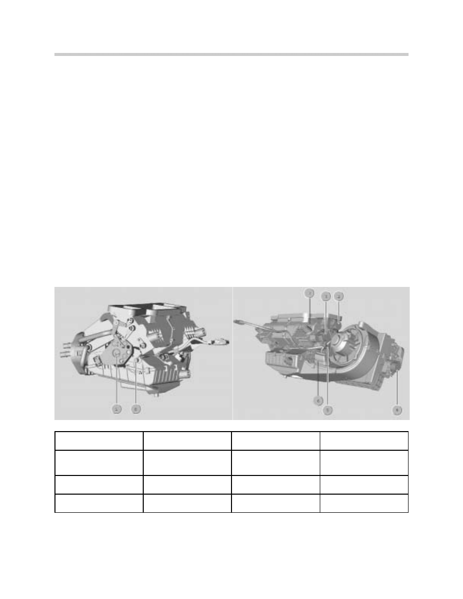
IHKA Heater/Air Conditioner
The following components are integrated in the IHKA heater/air conditioner:
• Actuator, fresh air/recirculating air flap
• Stepper motor, air distribution, bottom
• Stepper motor, air distribution, center
• Stepper motor, air distribution, top
• Stepper motor, mixed air flap
• Temperature sensor, mixed air
• Blower output final stage and blower motor
• Evaporator temperature sensor
1
Stepper Motor Air
Distribution, (defrost)
5
Stepper Motor, Mixed Air
Flap
2
Stepper Motor, Air
Distribution, Center
(Ventilation)
6
Blower Output Final Stage
3
Stepper Motor, Air
Distribution, (footwell)
7
Temperature Sensor, Mixed
Air
4
Actuator, fresh air/
Recirculating Air Flap
8
Evaporator Temperature
Sensor

17
E85 Heating/Air Conditioning System
Stepper Motors
The number of steps of the individual stepper motors depends on the adjustment range of
the driven flap as follows:
• Defrost, maximum number of steps 900, fail safe direction flap open
• Center ventilation, maximum number of steps 1390, fail safe direction flap closed
• Footwell, maximum number of steps 1600, fail safe direction flap closed
• Mixed air flap, maximum number of steps 1770, fail safe direction maximum warm
The flaps are moved to their limit stops after KL15 is switched “OFF”. The stepper motors
are not able to detect their actual position. The stepper motors always move relative to a
reference point. A flap end position (0% or 100%) serves as this reference point.
Evaporator Temperature Sensor
The evaporator temperature sensor is installed on the heater/air conditioner to measure the
temperature of the air flowing out at the evaporator.
The evaporator temperature sensor has a maximum value range from -49 ºF to 214 ºF. The
evaluation range of the evaporator temperature sensor is between 23 ºF and 77 ºF. Values
below -49 ºF are stored as a short to B+ or a break. Values above 214 ºF are stored as a
short to B-. The substitute value is 32 ºF.
Mixed Air Temperature Sensor
A mixed air temperature sensor is installed on the heater/air conditioner after the mixed air
flap to measure the mixed air temperature.
The mixed air temperature sensor has a value
range from -40 ºF to 221 ºF.
Values below -40 ºF are stored as a short to B+
or a break.
Values above 221 ºF are stored as a short to
B-. The substitute value is 131 ºF.
1. Temperature sensor, mixed air
2. Blower output final stage
18
E85 Heating/Air Conditioning System
Blower
The radial blower in the Z4 is mounted transversely in the heater/air conditioner. The blow-
er is activated when KL15 is switched “ON”, corresponding to the function previously
selected (DEFROST, MAX AC, automatic blower function, individual blower setting).
Blower activation takes place in linearly from 0 to 8 Volts. The IHKA is deactivated when the
blower is switched “OFF” (zero position). The blower activation is infinitely variable in AUTO
mode. The following 5 settings are possible for blower activation:
• Blower “OFF” (zero position)
• Individual blower setting
• Automatic blower (AUTO mode)
• DEFROST/MAX AC function with automatic blower setting
• DEFROST/MAX AC function with individual blower setting
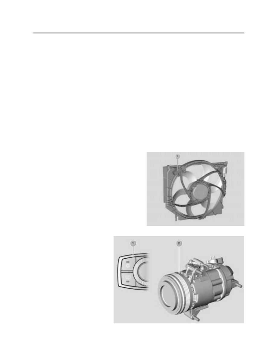
AUC Sensor
In automatic recirculating air control (AUC
mode), pollutant gasses are detected by the
AUC sensor. Based on this input, the IHKA
decides whether the system is to assume fresh
air mode or recirculating air mode.
The AUC sensor requires a warm up phase of
90 seconds. The AUC sensor is located on the
intake shroud of the electric cooling fan (1).
A/C Compressor
The magnetic clutch for the A/C
compressor is activated directly
by the IHKA control module.
1. A/C button on the IHKA control panel/
control module
2. A/C compressor

19
E85 Heating/Air Conditioning System
Air conditioning mode is activated by pressing the A/C button. The ECM is signalled to
increase the idle speed to compensate for the compressor load. On receiving the "A/C
compressor ON" request from the IHKA control module, the ECM responds with an enable
signal on a separate control wire providing no full load cutout request is active.
Consequently, the IHKA control module activates the A/C compressor magnetic clutch.
Switching conditions for the A/C compressor magnetic clutch:
A/C Compressor “ON”
• A/C button pressed and
• Evaporator temperature > 2 ºC (depending on outside temperature) and
• Outside temperature > - 10 ºC and
• System voltage > 9.7 V and
• Permissible refrigerant pressure range
A/C Compressor “OFF”
• Evaporator temperature < -0.5 ºC (depending on outside temperature) or
• Blower “OFF” (zero position) or
• Outside temperature < -10 ºC or
• KL15 switched “OFF” or
• System voltage < 9 V or
• Refrigerant pressure out of range (too low/high)
The current "Air conditioning ON" function is stored in the IHKA when KL15 is switched
“OFF”. Derived from the key memory (personalization), the function last selected is activat-
ed when KL15 is switched “ON”.
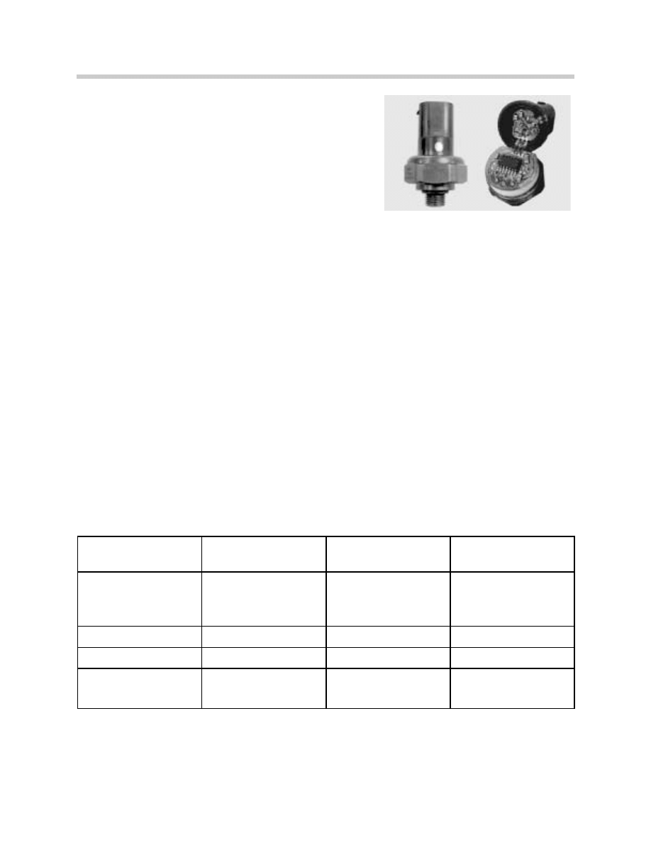
Pressure Monitoring
The pressure in the refrigerant circuit is monitored by a pressure sensor. The anticipated
A/C compressor load when switching on during operation is derived from the pressure sen-
sor signal.
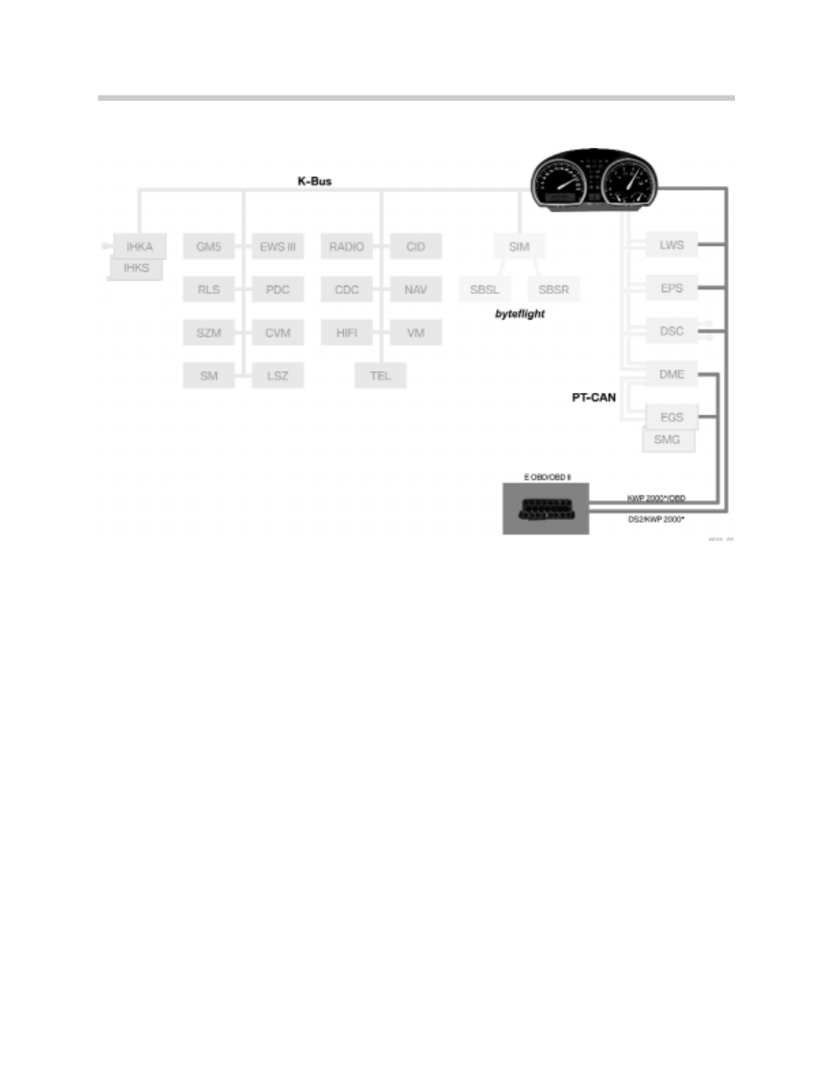
The load torque in transferred via the K-bus and PT-CAN bus to the ECM. The ECM
responds by adapting air and fuel volume. An upper and lower switching threshold is
defined for pressure monitoring:
Low Pressure
High Pressure
OFF <1.5 bar
OFF >32.0 bar
ON > 2.0 bar
ON < 24.0 bar
20
E85 Heating/Air Conditioning System
The pressure sensor is fitted in the pressure line near
the receiver/dryer. The supply voltage is 5 V and the
current is < 20 mA.
Depending on the system pressure, it supplies the
IHKA control module with an analog signal between
0.4 V and 4.6 V.
Rear Window Defogger
The rear window defogger has 3 operating statuses. Relay 1 for the rear window defogger
is always activated as if a hardtop were installed (no hardtop detection).
Defrost Phase is started only after the first time the rear window defogger button is pressed
after KL15 is switched “ON” (see following table for duration). Relay 2 for the rear window
defogger is activated at a rate of 100%. The system then assumes cyclic switching mode.
Cyclic Switching takes place with one third of the total power output of the rear window
defogger (pulse/pause ratio = 40 seconds ON/80 seconds OFF). Cyclic switching is deac-
tivated when KL15 is switched “OFF”.
Restart is possible if the rear window does not remain clear during or after cyclic switching.
The full power output can be resumed by pressing the rear window defogger button again.
The reheating phase is again followed by cyclic switching.
Operating Status
Defrost Phase
Cyclic Switching
Restart
Duration
10 minutes (outside tempera-
ture >15ºC)
17 minutes (outside tempera-
ture < -15ºC)
30 minutes
5 minutes
Function Light (LED)
ON
OFF
ON
Under Voltage Monitoring
Inactive
Active
Active
KL15 switched Off and On
again during afterrunning
period (sleep mode)
As before KL15 switched off OFF
As before KL15 switched Off

21
E85 Heating/Air Conditioning System
Rear Window Defogger Undervoltage/Overvoltage Monitoring
To prevent discharge when the vehicle electrical system is subject to high load at low engine
speeds (< 1500 rpm), the rear window defogger relays are switched off when the voltage
level drops or in the event of overvoltage (> 16 Volt for 5 seconds).
If the system voltage at the IHKA drops below 11.4 Volts, the rear window defogger is
switched off and only switched on again when the system voltage exceeds 12.2 Volts. The
threshold values must be applied for longer than 10 seconds.
Switching off the relays when undervoltage/overvoltage is detected has no influence on the
duration of the operating statuses (defrost phase, cyclic switching, restart) and the function
light (LED) remains on while the relays are switched off.
The rear window defogger is also switched off during engine start up (K-bus message,
KL50).
IHKA Principle of Operation
AUTO Mode
The following examples will be observed when operating the air distribution and the blow-
er controls:
• A high blower speed is set manually by the blower knob.
• When AUTO mode is selected, as the result of the previous manual setting, the rotary
knob is still set to high.
• Due to AUTO mode, the blower runs at medium speed.
• If the blower output is now to be increased slightly by turning the knob to the right, a very
large change occurs with the blower output.
Automatic Temperature Control
The temperature is controlled by mixing:
• Outside air that flows through the evaporator = cold air
• Outside air that initially flows through the evaporator and then through the heat exchang-
er (reheat) = warm air
22
E85 Heating/Air Conditioning System
While mixing the air, the IHKA temperature control determines a set position for the mixed
air flap to maintain the requested interior temperature. This set position is determined from
the inputs of:
• Vehicle interior temperature sensor
• Temperature sensor, mixed air
• Evaporator temperature sensor
The outside temperature and the coolant temperature are also used (transferred via K-bus
from the instrument cluster).
Automatic Air Distribution Control
There are 2 setting options for the air distribution:
• Individual setting of the air distribution
• Automatic air distribution (AUTO button)
The function light in the rotary knob for air distribution goes out when the AUTO button is
pressed. The IHKA control module sets the optimum air distribution corresponding to var-
ious inputs. Automatic blower mode remains active if the air distribution rotary knob is
turned manually during automatic air distribution. The function light in the AUTO button
goes out.

23
E85 Heating/Air Conditioning System
Automatic Air Volume Control
The air volume is controlled based on the position of the fresh air/recirculating air flap and
the blower speeds. The fresh air/recirculating air flap (a total of 3 individual flaps) is pow-
ered by an actuator.
The recirculating air mode is activated by pressing the AUC/recirculating air button. The
fresh air inlet is closed and the recirculating air channel opened. Air volume control features
a dynamic pressure compensation function.
The automatic blower and flap function as well as the function LED "AUTO" is activated by
pressing the AUTO button. The IHKA control unit sets the optimum blower speed and posi-
tion of the fresh air/recirculating air flap depending on various inputs.
Special Functions
MAX AC
The MAX AC function allows the user to request maximum cooling capacity with the sim-
ple push of a button. The prerequisite is that the outside temperature is > 50 ºF. The MAX
AC function is deactivated by pressing another button or turning a rotary knob.
In the MAX AC function, the blower speed can be adjusted
manually without exiting the MAX AC function. When ending
the MAX AC function, the settings that were active before MAX
AC are resumed.
The A/C compressor remains switched on after ending the
MAX AC function. Exception: The A/C compressor is switched
off when the MAX AC function is switched off via the A/C but-
ton.
DEFROST
Under certain circumstances the windows can fog up while driving (high humidity levels in
the vehicle interior). The DEFROST function can quickly remedy this situation by preventing
misting of the front field of vision. The DEFROST function assumes a higher ranking role in
air distribution control.
24
E85 Heating/Air Conditioning System
The DEFROST function can be activated as required even when IHKA is switched off (blow-
er zero position). The blower runs at full power. The blower output can be adjusted manu-
ally in DEFROST mode.
If KL15 is switched “OFF” with the DEFROST function active,
the DEFROST function is activated again KL15 is switched
“ON” within the afterrunning period (10 minutes).
The defrost function is deactivated by pressing another button
or turning a rotary knob. When ending the DEFROST function,
the settings that were active before DEFROST are resumed.
AUC/Recirculating Air
Automatic recirculating air control (AUC) is a standard feature
on E85 vehicles with IHKA. Initially, the AUC function is acti-
vated when the AUC/recirculating air button is pressed in fresh
air mode.
Pressing the button again activates the recirculating air mode.
Pressing the button once again returns to fresh air mode.
Recirculating air mode and AUC mode are indicated by green
function lights (LEDs) on the control panel.
As was the case with previous heating/air conditioning systems, the AUC/recirculating air
function also features "forced ventilation with fresh air," the activation and duration of which
depends on whether the system is in A/C mode (compressor active). The fresh air is already
dehumidified if the A/C compressor is ON, therefore, the duration of recirculating air mode
is longer.
"Forced ventilation" cycles:
A/C Button
Cycle
Off
3 minutes recirculating air
1 minute fresh air
ON
12 Minutes recirculating air
1 minute fresh air

25
E85 Heating/Air Conditioning System
Cold Start Interlock
The cold start interlock function intervenes in activation of the air distribution flaps and
blower control. The cold start interlock is active at low outside temperatures and low
coolant temperatures (engine cold) to prevent cold air distribution until warm air is available.
In the E85, the cold start interlock is not deactivated by a terminal change from KL15 “ON”
to “OFF”. When the switch on conditions are fulfilled, the defrost air distribution flap is fully
opened and the ventilation and footwell air distribution flaps are completely closed. As a
result, no cold air is blown directly at the driver/passenger.
The automatic blower function must be selected for intervention in blower control.
Cooling Mode
Cooling mode serves the purpose of cooling a heated vehicle by forced air recirculation at
high outside temperatures. Cooling mode is active during engine start and applies both in
AUTO mode and manual mode. The A/C compressor must also be activated.
Cooling mode supersedes the AUC function. If the signal from the AUC sensor specifies
fresh air mode, recirculating air mode is retained or set to a fresh air share of 20% when
cooling mode is active.
An E85 feature is that cooling mode is extended from 12 to 15 minutes in tropics coding
(hot country). When the control variable (y-factor) is below -90%, the fresh air/recirculating
air flap is set to recirculating air for maximum 12 minutes. As a result, warm air is not blown
directly at the driver/passenger.
After this period of 12 minutes has elapsed, if the control variable is below -90%, the fresh
air/recirculating air flap is set to 20% fresh air.
Avoiding Fogging During Start
This function is activated once with KL15 “ON” in automatic mode. The prerequisite is that
the outside temperature is above 32 ºF. The defrost air distribution flap is closed for 12 sec-
onds. Consequently, windshield fogging caused by moist air from the evaporator is avoid-
ed.
This function is superseded by the cold start interlock. In this case, all air distribution flaps
are closed.
26
E85 Heating/Air Conditioning System
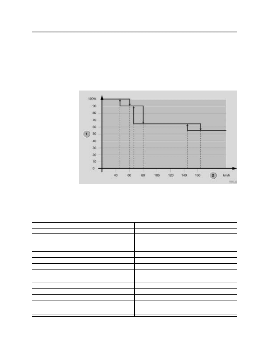
Dynamic Pressure Compensation
To prevent uneven air volume as driving speeds vary, dynamic pressure is compensated by
the fresh air flap reducing the fresh air inlet opening as the vehicle speed increases. The
vehicle speed is made available via the K-bus from the instrument cluster. The fresh air flap
reduces the opening angle within a certain speed range according to a characteristic curve.
The calculation of the flap position is dampened to avoid continual flap activation as a result
of variations in vehicle speed.
1. Fresh air flap opening
angle
2. Vehicle speed
Electric Cooling Fan
The electric cooling fan is activated by the ECM that outputs the control voltage for the final
stage of the fan. Activation for the correct fan speed (15 speeds) is derived by the IHKA
control module from the refrigerant pressure sensor signal and sent to the ECM.
Refrigerant pressure in bar
Fan Speed
8
0
9
2
10
3
12
5
14
6
15
7
16
8
17
9
18
10
19
11
20
12
21
13
22
14
23 - 35
15
Workshop Hints
Transport Mode
To preserve the vehicle battery during vehicle transport, IHKA is deactivated. Transport
mode is set during vehicle production and must be disabled prior to vehicle delivery.
Transport mode is deactivated with the DISplus/GT1 under Service Function "Disable trans-
port mode."
AUC Test Mode
Differing from the E46, there is no button combination provided on the control panel that
enables a test mode for AUC.
Compressor Run-In Protection
Compressor run-in protection is started automatically after installing a new control panel/
control module (important for initial assembly at the factory). The switch on conditions for
the compressor, e.g. the outside temperature, are disregarded.
Note: This function has a duration of 90 seconds (with engine running at idle speed). The
function light in the A/C button flashes during this period.
kt-9939
27
E85 Heating/Air Conditioning System

28
E85 Heating/Air Conditioning System
Vehicle & Key Memory (VKM)
The following table shows the vehicle & key memory functions for E85 IHKA.
Coding
Tropics coding IHKA - The recirculating air function is retained after a new start. In addition,
a previously selected recirculating air function is reactivated when the defrost function is
switched off. In both cases, the tropics coding prevents moist warm air from the outside
flowing into the vehicle interior.
Hot country coding IHKA - In the hot country coding, the increased cooling capacity is
achieved by increasing the blower output.
Control panel/control unit coding - The function light on the button for the rear window
defogger flashes if the control panel/control unit is not encoded. For instance, right-hand
drive or left-hand drive must be coded for activation of the stepper motors to ensure the
correct bus addresses are used.
Vehicle memory
Setting
Explanation
Key Memory
Active/not Active
Key memory can be activated/deactivated. When
active, various functions are stored key specific.
Memory Recirculation air
Active/not Active
The recirculation air function is retained after a new
start.
Cooling Capacity
Normal/hot country
Cooling capacity EU or hot country (increased cool-
ing capacity by correspondingly increasing the blow-
er output
Key Memory
Setting
Explanation
Blower output
Increase/normal/decrease
The blower output in automatic mode can be
increased or decreased
Correction set temperature
+3º/+2º/+1º/normal /-1º/-2º/-3º The temperature set at the control panel can be
corrected accordingly.
Air Conditioning mode “ON”
Active/not active
The air conditioning is switched on by switching on
the ignition or by pressing the button on the control
panel.
The following table shows the vehicle & key memory functions for E85 IHKS.
Vehicle Memory
Setting
Explanation
Key Memory
Active/not active
Key memory can be active/deactived. When active,
various functions are stored key-specific
Memory recirculating air
Active/not active
The recirculation air function is retained after a new
start.
Key Memory
Setting
Explanation
A/C mode “ON”
Active/not active
The air conditioning is switched on by switching on
the ignition or by pressing the button on the control
panel.
29
E85 Heating/Air Conditioning System
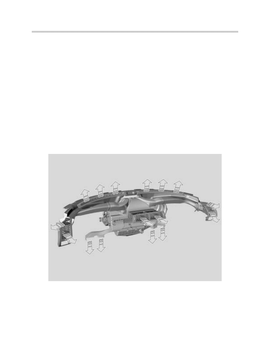
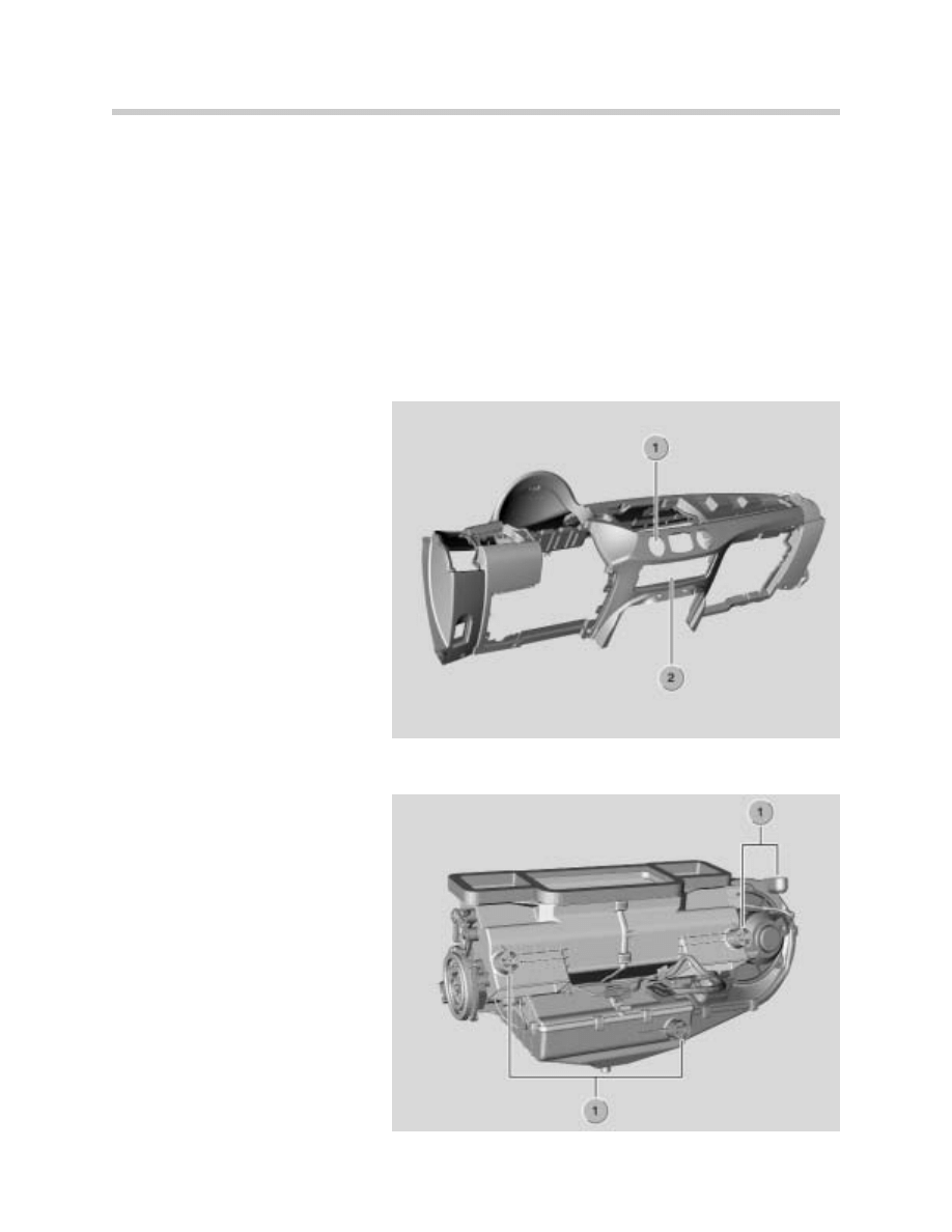
Control Panel/Control Module Mounting
The “island” design requires a different mounting concept. The control panel/control mod-
ule is mounted from the rear in the instrument panel. 3 trim rings can be individually
replaced from the front. The control panel/control module is secured by 2 side clips and 2
screws at the top.
The IHKS control panel/control module can only be replaced as a complete unit. Individual
parts such as rotary knobs cannot be replaced. To remove this, it is first necessary to
remove the center fresh air grille outlet and the radio. The control panel/control module can
then be removed by pulling down through the service opening in the instrument panel.
Note: Particular care must be
taken when removing the control
panel/control module to avoid
scratches on the front of the unit.
1. Mounting opening for the control
panel/control module.
2. Service opening for the control
panel/control module.
Heater/Air Conditioner Mounting
The heater/air conditioner is
mounted by 4 mounting domes
on the support tube between the
A pillars.
The heater/air conditioner is
secured by 4 plastic screws. The
plastic screws can be reused sev-
eral times. Repair kits for the
mounting domes are available.
1. Mounting domes
30
E85 Heating/Air Conditioning System
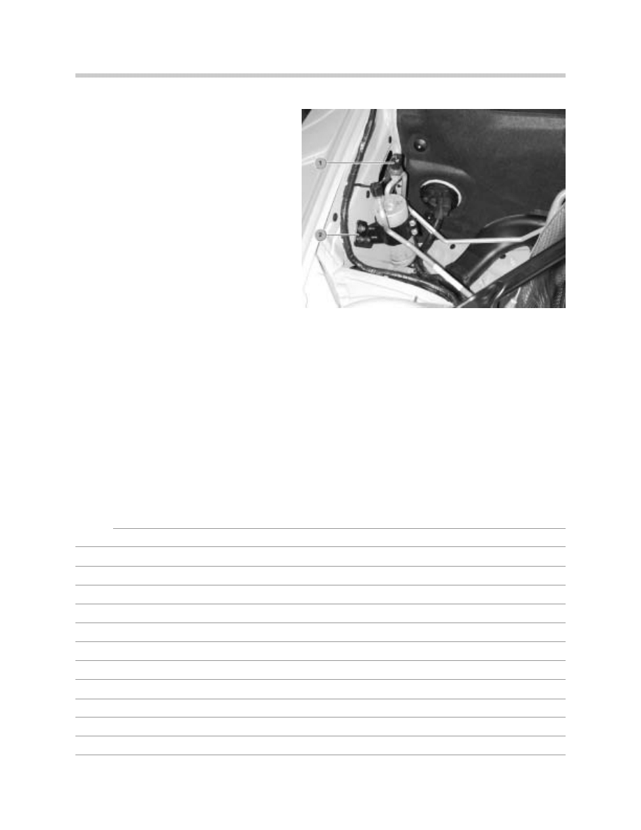
Receiver/Dryer Mounting
The receiver/dryer is mounted with a
plastic bracket to the right wheel arch
behind the strut tower.
The refrigerant pressure sensor is
installed on the refrigerant line leading to
the receiver/dryer.
1. Refrigerant pressure sensor
2. Plastic receiver/dryer bracket
Microfilter
The microfilter is located in the heater/air conditioner unit and is accessed via the footwell
on the passenger's side below the glove box.
Notes:

31
E85 Heating/Air Conditioning System
Review Questions
1. What are the “visual” differences that identify IHKA from IHKS?
2. How are 3 sets of distribution flaps controlled by one stepper motor on the IHKS sys-
tem?
3. Where is the microfilter accessed for service?
4. If the interior temperature sensor blower failed, what would be the customer complaint
(IHKA)?
5. What occurs with the A/C compressor when MAX AC is switched off (IHKA)?
6. What is Transportation Mode?
Document Outline
- Main Menu
- Climate Control P1
- Climate Control P2
- Climate Control P3
- IHKS
- IHKS E52
- Understanding Climate Control
- Understanding Solar Sensors
- IHKA E38
- IHKA E39
- IHKR E39
- IHKR & IHKA E53
- IHKA E46
- IHKR E46
- IHKA E36
- Inputs
- Outputs
- E85 Heating / Air Conditioning Sys.
- E65 IHKA
- Rear Air Conditioning Sys.
- Updates
Wyszukiwarka
Podobne podstrony:
ti 1102 Transporter 2004 Heating and Air Conditioning
0502 Refrigerant circuit Model 126 with air conditioning system
Filtration and Air Cleaning Systems
E38 Air Conditioning System
Dehydration of Carrots by a Combination of Freeze Drying, Microwave Heating and Air or Vacuum Drying
Audel Hvac Fundamentals, Air Conditioning, Heat Pumps And Distribution Systems (Malestrom)
M37a1 Heating and Ventilation System 1 17
Audel Hvac Fundamentals, Air Conditioning, Heat Pumps And Distribution Systems (Malestrom)
M37a2 Heating and Ventilation System 18 32
SAF HOLLAND Air suspension systems and axles with drum brakes pl DE
SAF HOLLAND Air suspension systems and axles with dru(1)
07 E85 Heating & Air Cond
04d E85 Info and Communication Systems
SR 8 Adaptive Air Conditioning ULA[1]
Popular Mechanics Finding And Fixing Water And Air Leaks
Farina Reproduction of auditorium spatial impression with binaural and stereophonic sound systems
więcej podobnych podstron