Publications No.
Issue Date
INSTALLATION
INSTRUCTIONS
Accessory
Application
© 2008 American Honda Motor Co., Inc. – All Rights Reserved
AII 40412 (0808)
1 of 8
08V03-SWA-1000-91
AII 40412
AUTOMATIC DAY/NIGHT
MIRROR
2009 CR-V
AUG 2008
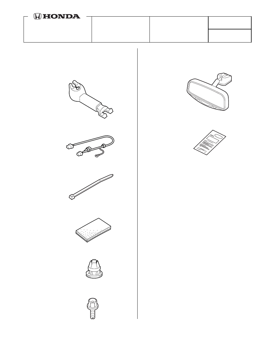
PARTS LIST
Automatic Day/Night Mirror Attachment Kit
P/N 08V03-SWA-100
Harness cover set
Automatic Day/Night mirror harness
9
Wire ties
4
EPT sealers
Clip
Ground bolt
Automatic Day/Night Mirror Kit
P/N 08V03-S9A-100B
Day/Night mirror
Operating Instructions
TOOLS AND SUPPLIES REQUIRED
Phillips screwdriver
Flat-tip screwdriver
Ratchet
10 mm Socket
Isopropyl alcohol
Shop towel
Diagonal cutters
T-20 and T-25 TORX bits
Needle nose pliers
Steel wire
2 of 8
AII 40412 (0808)
© 2008 American Honda Motor Co., Inc. – All Rights Reserved
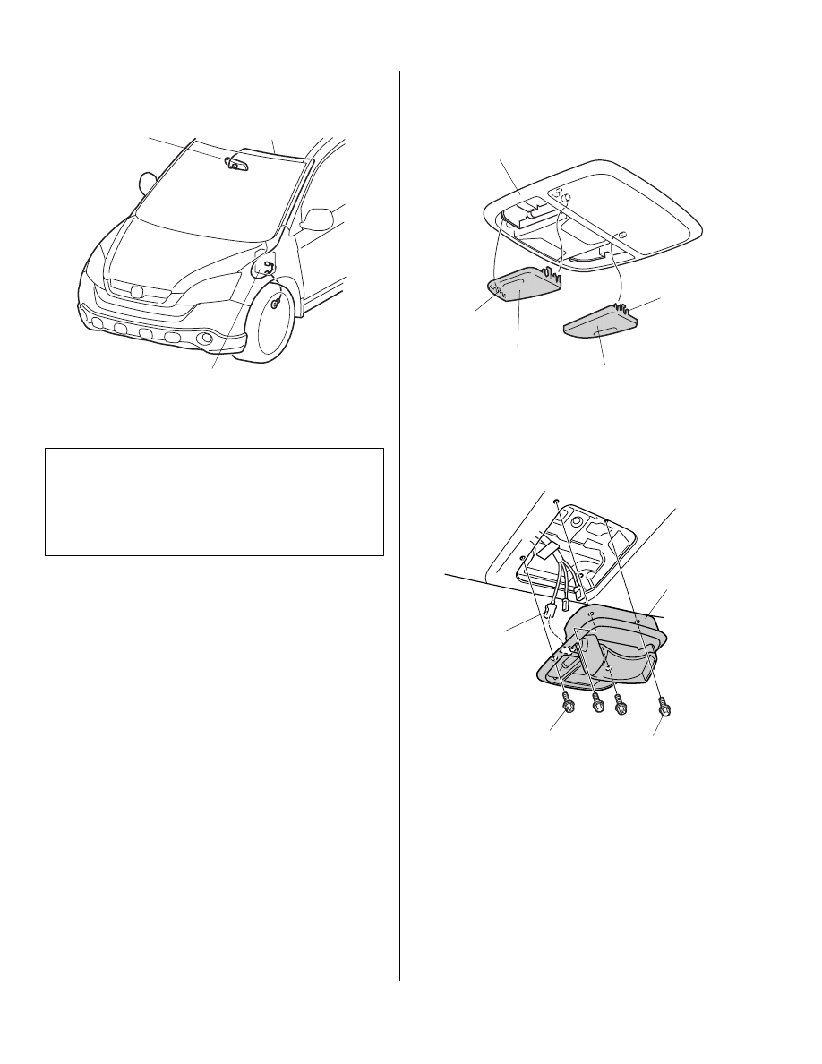
Illustration of the Day/Night MIirror
Installed on the Vehicle
INSTALLATION
1.
Make sure you have the anti-theft code for the radio,
then write down radio station presets.
2.
Disconnect the negative cable from the battery.
Customer Information: The information in this
installation instruction is intended for use only by skilled
technicians who have the proper tools, equipment, and
training to correctly and safely add equipment to your
vehicle. These procedures should not be attempted by
“do-it-yourselfers.”
6312070B
MIRROR
HARNESS
FUSE BOX
DAY/NIGHT
MIRROR
3.
Carefully remove the right and left map light lens
from the roof console (four tabs for each lens).
4.
Remove the roof console (four bolts and unplug the
vehicle connectors).
6308150Y
RIGHT MAP
LIGHT LENS
4 RETAINING
TABS
LEFT MAP
LIGHT LENS
4 RETAINING
TABS
ROOF
CONSOLE
6313021Y
VEHICLE
CONNECTOR
SILVER
BOLTS
ROOF
CONSOLE
BLACK
BOLTS
© 2008 American Honda Motor Co., Inc. – All Rights Reserved
AII 40412 (0808)
3 of 8
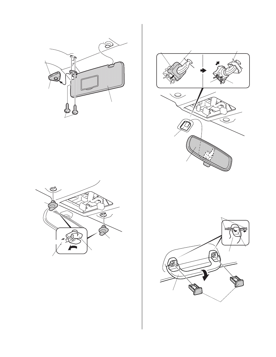
5.
Remove the cover from the left sunvisor (four
retaining tabs).
6.
Remove the two T-25 TORX screws, pull out the left
sun visor, and remove the sunvisor.
7.
Remove the right and left sunvisor holders. Using a
flat-tip screwdriver, push in on the tab and rotate the
holder.
6311
LEFT SUNVISOR
TORX
SCREWS
COVER
4 RETAINING
TABS
6308170Y
Push.
RIGHT
SUNVISOR
HOLDER
FLAT-TIP
SCREWDRIVER
Turn.
2 SUNVISOR
HOLDERS
LEFT
SUNVISOR
HOLDER
8.
Remove the cover from the mirror (two retaining
tabs). Lift up the mirror while pulling the base,
and remove the mirror.
9.
Using a flat-tip screwdriver, remove the two caps
from the left front grab rail.
6823040B
MIRROR
BASE
MIRROR
MIRROR
Pull.
2 RETAINING
TABS
BASE
COVER
Lift up.
6311161B
LEFT FRONT
GRAB RAIL
CAPS
2 CAPS
FLAT-TIP
SCREWDRIVER
LEFT FRONT
GRAB RAIL
4 of 8
AII 40412 (0808)
© 2008 American Honda Motor Co., Inc. – All Rights Reserved
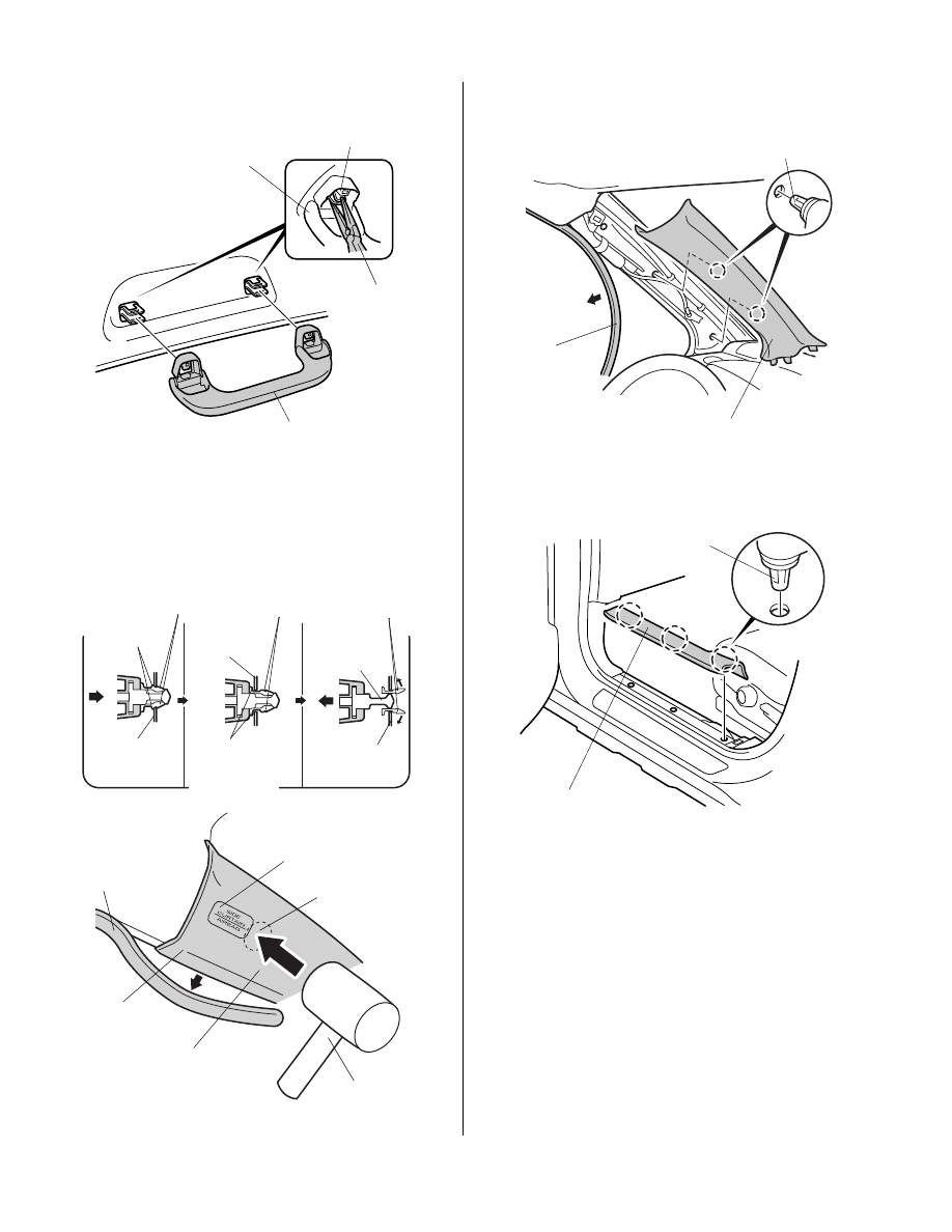
10. Using needle nose pliers, remove the left front grab
rail (two clips).
11.
Remove the front door opening seal around the
A-pillar trim. Using a rubber mallet, strike the top of
the A-pillar trim, in the area marked “SIDE CURTAIN
AIRBAG”, to release the clip. Remove the clip.
6311170B
LEFT FRONT
GRAB RAIL
LEFT FRONT
GRAB RAIL
NEEDLE
NOSE
PLIERS
2 CLIPS
VEHICLE
CLIP
VEHICLE
CLIP
Pushed deep
behind the
vehicle panel.
RETAINING
TAB
Collapsed.
PIN
Comes off
from the clip.
RETAINING
TAB
Tap.
VEHICLE CLIP
Remains on the
vehicle panel.
VEHICLE
BODY
VEHICLE
BODY
PART MARKED AS
“SIDE CURTAIN AIRBAG”
Tap at right angles
to the vehicle.
LEFT FRONT
A-PILLAR TRIM
VEHICLE
BODY
Pull.
VEHICLE
CLIP
DOOR
OPENING
SEAL
Tap with a rubber
mallet.
12. Remove the left A-pillar trim (two clips).
13. Remove the left front door sill trim (three clips).
6311181B
DOOR
OPENING
SEAL
2 CLIPS
LEFT A-PILLAR
TRIM
6303090B
3 CLIPS
LEFT FRONT DOOR
SILL TRIM
© 2008 American Honda Motor Co., Inc. – All Rights Reserved
AII 40412 (0808)
5 of 8
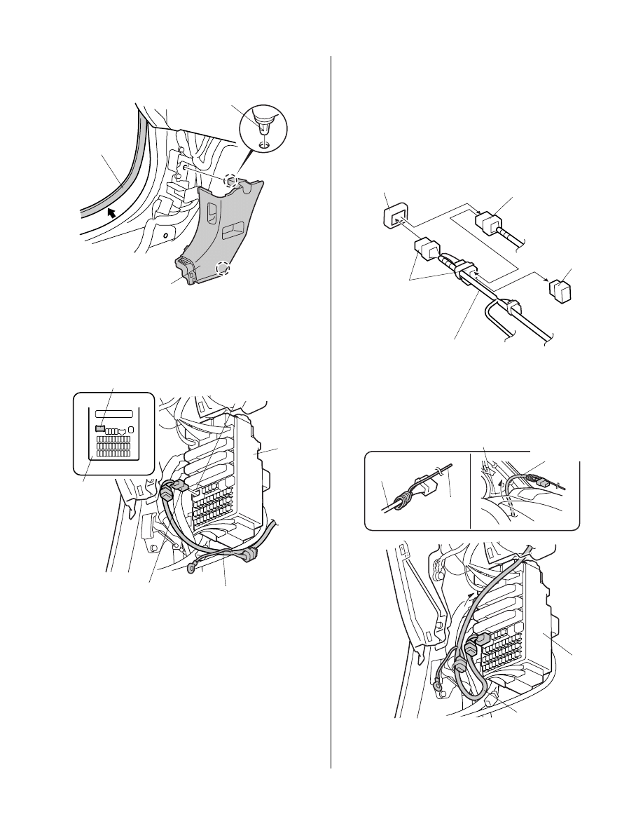
14. Remove the front door opening seal from around the
left kick panel. Remove the left kick panel (two clips).
15. Plug the automatic day/night mirror harness 6-pin
connector into the empty 6-pin connector opening of
the fuse box.
6303100B
2 CLIPS
DOOR OPENING
SEAL
LEFT KICK
PANEL
6312022B
AUTOMATIC DAY/
NIGHT MIRROR
HARNESS
AUTOMATIC DAY/
NIGHT MIRROR
HARNESS 6-PIN
CONNECTOR
FUSE
BOX
FUSE BOX
FUSE BOX OPEN
6-PIN CONNECTOR
FUSE BOX OPEN
6-PIN CONNECTOR
NOTE: If another accessory is already plugged into the 6-
pin connector opening of the fuse box, remove the dummy
connector from the 6-pin connector taped to the automatic
day/night mirror harness. Plug the 6-pin connector from
the other accessory harness into the 6-pin connector from
the automatic day/night mirror harness you just
unplugged and plug the automatic day/night mirror
harness into the 6-pin connector opening of the fuse box.
16. Attach a piece of steel wire to the automatic day/
night mirror harness, and route it through the left
front pillar trim opening.
AUTOMATIC DAY/
NIGHT MIRROR
HARNESS
AUTOMATIC DAY/
NIGHT MIRROR
HARNESS 6-PIN
CONNECTOR
6-PIN CONNECTOR
OPENING of the
FUSE BOX
OTHER ACCESSORY
6-PIN CONNECTOR
DUMMY
CONNECTOR
6627080B
AUTOMATIC
DAY/NIGHT
MIRROR
FUSE
BOX
STEEL
WIRE
LEFT FRONT PILLAR
TRIM OPENING
AUTOMATIC DAY/
NIGHT MIRROR
HARNESS
AUTOMATIC DAY/NIGHT
MIRROR HARNESS
6 of 8
AII 40412 (0808)
© 2008 American Honda Motor Co., Inc. – All Rights Reserved
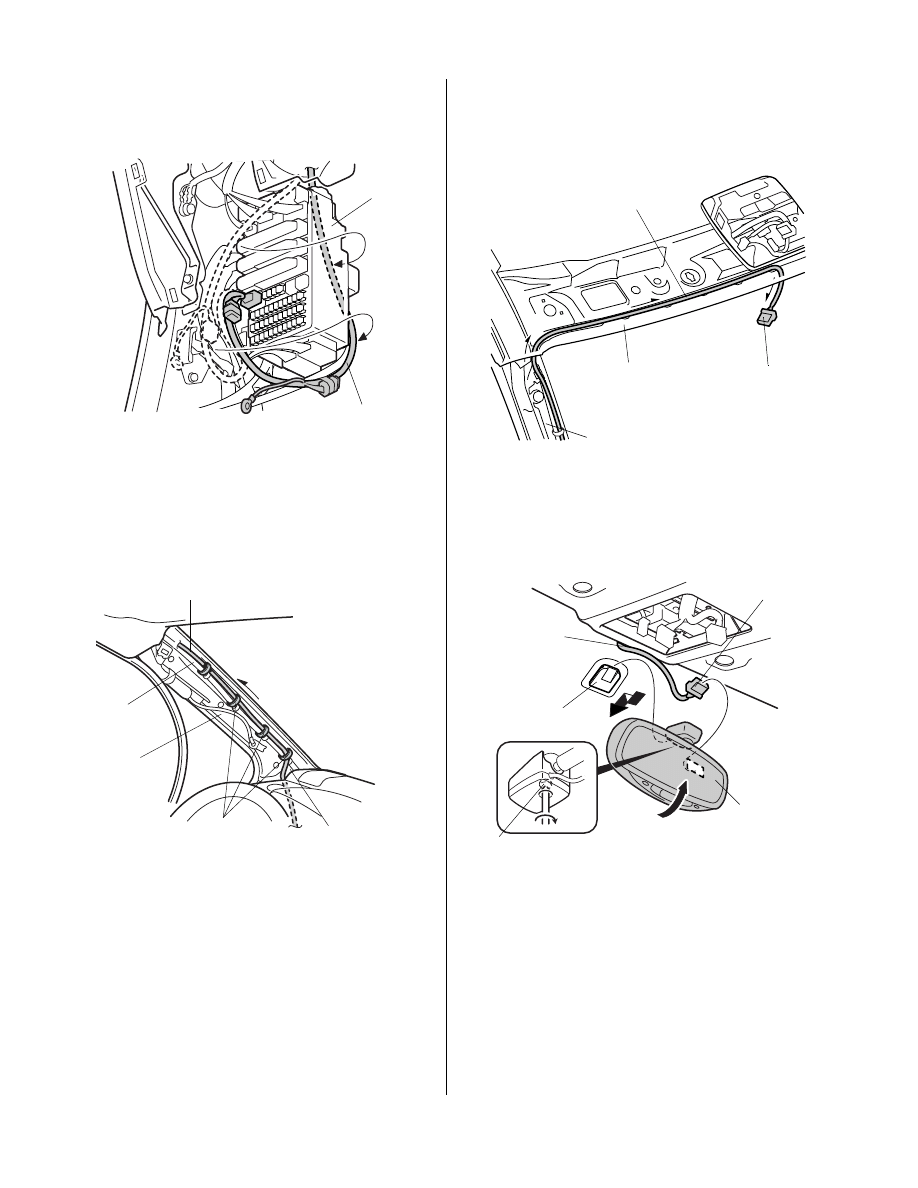
17. Route the automatic day/night mirror harness behind
the fuse box.
18. Remove the steel wire. Route the automatic day/
night mirror harness along the vehicle harness as
shown. Loosely secure the day/night mirror harness
to the vehicle harness with the four wire ties.
6627090B
FUSE
BOX
AUTOMATIC DAY/
NIGHT MIRROR
HARNESS
6823010B
AUTOMATIC DAY/
NIGHT MIRROR
HARNESS
WIRE TIE
VEHICLE
HARNESS
LEFT
A- PILLAR
LEFT FRONT
PILLAR TRIM
OPENING
19. Route the automatic day/night mirror harness above
the headliner from the left A-pillar to the middle of the
vehicle.
20. Plug the automatic day/night mirror into the day/night
mirror 7-pin connector.
21. Install the day/night mirror on the mirror base,
then tighten the T-20 TORX screw installed in the
day/night mirror.
6311191B
LEFT A-PILLAR
AUTOMATIC DAY/
NIGHT MIRROR
HARNESS 7-PIN
CONNECTOR
HEADLINER
AUTOMATIC DAY/
NIGHT MIRROR
HARNESS
6311202B
AUTOMATIC DAY/
NIGHT MIRROR
HARNESS
AUTOMATIC DAY/
NIGHT MIRROR
HARNESS 7-PIN
CONNECTOR
AUTOMATIC DAY/
NIGHT MIRROR
MIRROR
BASE
TORX
SCREW
Up.
© 2008 American Honda Motor Co., Inc. – All Rights Reserved
AII 40412 (0808)
7 of 8
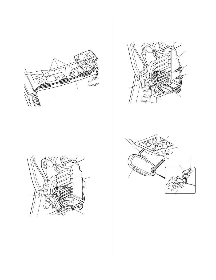
22. Using isopropyl alcohol on a shop towel, thoroughly
clean the areas where the EPT sealer will attach.
Secure the automatic day/night mirror harness to the
headliner with three EPT sealers.
23. Pull the slack in the automatic day/night mirror
harness down the A-pillar to the fuse box. Tighten
the four wire ties installed in step 18.
24. Secure the automatic day/night mirror harness to the
vehicle harness with the two wire ties in the areas
shown.
6311211B
AUTOMATIC DAY/
NIGHT MIRROR
HARNESS
HEADLINER
EPT SEALERS
6312042B
AUTOMATIC DAY/
NIGHT MIRROR
HARNESS
WIRE TIE
WIRE
TIE
FUSE
BOX
25. Remove the vehicle bolt from the fuel lid opener.
Attach the automatic day/night mirror harness
ground terminal with the ground bolt supplied.
26. Install the harness cover to the automatic day/night
mirror and the headliner.
6823030B
FUSE
BOX
GROUND
BOLT
AUTOMATIC
DAY/NIGHT
MIRROR
HARNESS
AUTOMATIC DAY/NIGHT HAR-
NESS GROUND TERMINAL
VEHICLE
BOLT
(Not used)
FUEL LID
OPENER
6312062B
AUTOMATIC DAY/
NIGHT MIRROR
HARNESS
HARNESS
COVER
HEADLINER
AUTOMATIC DAY/
NIGHT MIRROR
HARNESS
AUTOMATIC DAY/
NIGHT MIRROR
AUTOMATIC DAY/
NIGHT MIRROR
8 of 8
AII 40412 (0808)
© 2008 American Honda Motor Co., Inc. – All Rights Reserved
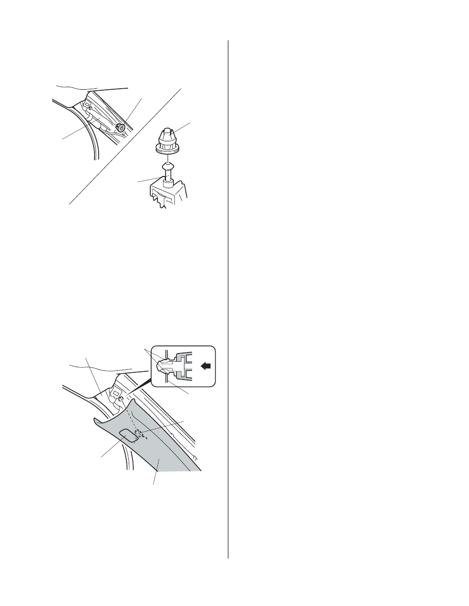
27. Remove and discard the upper vehicle clip from the
left A-pillar.
28. Check that the left A-pillar trim and the pin are not
damaged, then, install the new clip from the kit on the
pin.
29. Position the clip at right angles near the hole in the
left A-pillar. Install the clip by lightly pushing the left
A-pillar trim at the part marked as “SIDE CURTAIN
AIRBAG”. Check that the airbag is not pinched with
the clip, and be careful not to push the left A-pillar
trim excessively.
6305010H
CLIP
VEHICLE
CLIP
Remove.
LEFT
A-PILLAR
TRIM PIN
LEFT
A-PILLAR
65190
CLIP
LEFT
A-PILLAR
CLIP
PART MARKED AS
“SIDE CURTAIN AIRBAG”
LEFT A-PILLAR
TRIM
VEHICLE
PANEL
30. Check that all wire harnesses are routed properly
and all connectors are plugged in.
31. Reinstall all removed parts.
32. Reconnect the negative cable to the battery.
33. Enter the customer’s audio and navigation system
(if equipped) anti-theft codes, and reset the XM radio
presets.
34. Reset the clock.
NOTE: Check the operation of the automatic day/night
mirror according to the Operating Instructions supplied.
Place the Operating Instructions in the glove box for your
customer.
Wyszukiwarka
Podobne podstrony:
więcej podobnych podstron