Hepworth Heating Ltd.,
Nottingham Road, Belper, Derbyshire. DE56 1JT
General/Sales enquiries:
Tel: (01773) 824141 Fax: (01773) 820569
One Contact Local Service
Customer Services:
Tel: (01773) 828100
Fax: (01773) 828070
221808B.12.00
All replacement parts
All labour charges
All call-out charges
Guarantee Registration
Hideaway 50
Open Flue Boiler
This is a Cat I
2H
Appliance
BS 6332
BS 5258
Reference in these instructions to British Standards and Statutory
Regulations/Requirements apply only to the United Kingdom.
For Ireland the rules in force must be used.
T o b e l e f t w i t h t h e u s e r
1037
❏
✔
❏
✔
❏
✔
Instructions for Use
Installation and Servicing
G.C. No. 41 313 15
REGISTER YOUR GLOW-WORM APPLIANCE
FOR 1ST YEAR GUARANTEE PROTECTION
CALL 0208 247 9857
Thank you for installing a new Glow-worm appliance in your home.
Glow-worm appliances' are manufactured to the very highest standard so we are pleased
to offer our customers' a Comprehensive First Year Guarantee.
In the center pages are to be found your Guarantee Registration Card, which we recommend you complete and
return as soon as possible.
If this card is missing you can obtain a copy or record your registration by telephoning the Heatcall Customer
Service number 01773 828100.
Our Guarantee gives you peace of mind plus valuable protection against breakdown by covering the cost of:
The instructions consist of three parts, User, Installation and Servicing Instructions, which includes the Guarantee Registration
Card. The instructions are an integral part of the appliance and must, to comply with the current issue of the Gas Safety
(Installation and Use) Regulations, be handed to the user on completion of the installation.

2
221808B
Notes and General Information
Please read these instructions and follow them carefully for the
safe and economical use of your boiler.
The boiler is automatic in operation, once the pilot is lit and the
controls have been set.
Glow-worm Hideaways’ are central heating boilers, to provide
heating and if required an indirect domestic hot water supply.
Important Notice
This boiler is for use only on G20 gas.
Gas Safety (Installation and Use) Regulations
In your own interests and that of safety, it is the Law that ALL gas
appliances are installed by a competent person in accordance
with the current issue of the above regulations.
CE Mark
This boiler meets the requirements of Statutory Instrument, No.
3083 The Boiler Efficiency Regulations, and therefore is deemed
to meet the requirements of Directive 92/42/EEC on the efficiency
requirements for new hot water boilers fired with liquid or
gaseous fuels.
Type test for purposes of Regulation 5 certified by:
Notified body 0086.
Product/production certified:
Notified body 0086.
The CE Mark on this appliance shows compliance with:
1. Directive 90/396/EEC on the approximation of the Laws of
the Member States relating to appliances burning gaseous
fuels.
2. Directive 73/23/EEC on the harmonization of the Laws of the
Member States relating to electrical equipment designed for
use within certain voltage limits.
3. Directive 89/336/EEC on the approximation of the Laws of
the Members States relating to electromagnetic
compatibility.Information for the Installer and Service Engineer.
Control of Substances Hazardous to Health
Under Section 6 of The Health and Safety at Work Act 1974, we
are required to provide information on substances hazardous to
health.
The adhesives and sealants used in this appliance are cured
and give no known hazard in this state.
Insulation Pads/Ceramic Fibre, Glassyarn
These can cause irritation to skin, eyes and the respiratory tract.
If you have a history of skin complaint you may be susceptible
to irritation. High dust levels are usual only if the material is
broken.
Normal handling should not cause discomfort, but follow normal
good hygiene and wash your hands before eating, drinking or
going to the lavatory.
If you do suffer irritation to the eyes or severe irritation to the skin
seek medical attention.
Boiler Thermostat
These contain very small amounts of xylene in the sealed phial
and capillary. If broken, under normal circumstances the fluid
does not cause a problem, but in cases of skin contact, wash
with cold water.
If swallowed drink plenty of water and seek medical attention.
Important Information
Introduction
3
Lighting the Boiler
4
General Data
1
5
Water Systems
2
7
Flue and Ventilation
3
8
Installation
4
9
Casing Location
5
11
Electrical Wiring
6
11
Commissioning
7
12
Servicing
8
15
Replacement Parts
9
17
Fault Finding
10
20
Spare Parts
11
24
CONTENTS
DESCRIPTION SECTION
PAGE No.
INSTRUCTIONS
FOR USE
INSTALLATION
INSTRUCTIONS
SERVICING
INSTRUCTIONS
3
221808B
Warning
Make sure that nothing obstructs the rear side grilles or
clearances. See diagram 1.2 and 1.3 for minimum clearances.
Boilers Installed in a Compartment
If the boiler is fitted in a compartment, cupboard etc., do not
obstruct the purpose built compartment vents or grille on the
boiler.
Do not use the compartment for storage purposes.
Maintenance
To ensure the continued efficient and safe operation of the
boiler it is recommended that it is checked and serviced at
regular intervals. The frequency of servicing will depend upon
the particular installation conditions and usage, but in general
once a year should be enough.
If this appliance is installed in a rented property there is a duty
of care imposed on the owner of the property by the current
issue of the Gas Safety (Installation and Use) Regulations,
Section 35.
It is the law that servicing is carried out by a competent person.
To obtain service please call your installer or Heatcall (Glow-
worm’s own service organisation) using the telephone number
given on the inside of the front panel.
Please be advised that the ‘Benchmark’ logbook should be
completed by the installation engineer on completion of
commissioning and servicing.
All CORGI Registered Installers carry a CORGI ID card, and
have a registration number. Both should be recorded in your
boiler Logbook. You can check your installer is CORGI registered
by calling CORGI direct on :- 01256 372300.
Boiler Electrical Supply
WARNING. This boiler must be earthed.
The boiler must only be connected to a 240V~50Hz supply,
protected by a 3A fuse, maximum.
All wiring must be in accordance with the current issue of
BS7671.
Heat resistant cable having a conductor size of 0.75mm
2
, (24/
0.22mm), to BS6500 Table 16 must be used.
To Connect an Electrical Plug
The colours of three core flexible cable are, Brown - live, Blue
- neutral, Green and yellow - earth.
As the markings on your plug may not correspond with these
colours continue as follows:
The wire coloured brown must be connected to the terminal
marked “L” or Red.
The wire coloured blue must be connected to the terminal
marked “N” or Black.
The wire coloured green and yellow must be connected to the
terminal marked “E”, Green or the earth symbol
.
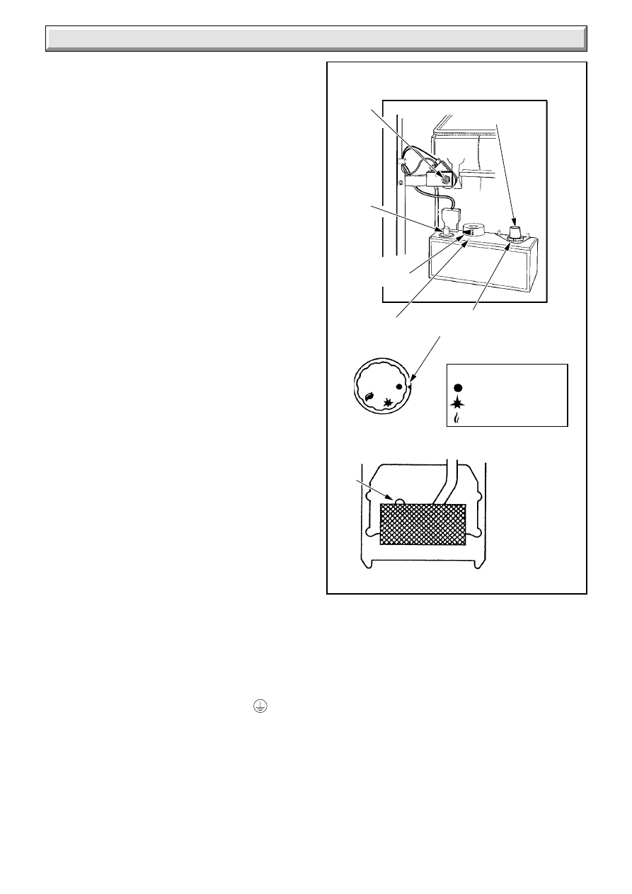
SETTING
POINTS
FLUE
BLOCKAGE
SAFETY
DEVICE
RESET
BUTTON
50 OPEN FLUE
SETTING
POINT
GAS CONTROL
KNOB 'A'
THERMOSTAT
CONTROL
KNOB 'B'
GAS CONTROL KNOB
= OFF
= PILOT/IGNITION
= MAIN BURNER
E
0938
PIEZO
IGNITION
BUTTON
'C'
Diagram 1
Instructions for Use
Safety Device
This appliance is fitted with a flue blockage safety device which
will shut down the appliance in the event of abnormal flue
conditions. This device is NOT a substitute for an independently
mounted Carbon Monoxide detector.
The safety device is reset, after three minutes, by pushing in the
button shown in diagram 1.
Shut down can occur during certain climate conditions, but if it
recurs the chimney flue and air inlet into the room must be
checked and any problems found corrected by a competent
person, before the boiler is used again.

4
221808B
To Light the Boiler
WARNING. If the pilot light goes out for any reason, do not
attempt to relight until three minutes have gone by.
Remove the door by pulling forwards with the fascia at the top.
Lift up to free from bottom side lugs.
Refer to diagram 1 to identify the controls.
Check that the mains electrical supply to the boiler is switched
OFF.
Check that the Flue Blockage Safety Device has not operated,
that is, the button is in. Refer to Safety Device instructions.
Push in slightly and turn gas control knob “A” clockwise until
'
'is against its setting point.
Turn thermostat control knob “B” anticlockwise until “O” is
against its setting point.
Push in slightly and turn gas control knob “A” anticlockwise until
'
' is against its setting point, then push fully and hold in.
Push and release piezo ignition button “C” until the pilot burner
lights.
Air may be present in the supply pipe so the lighting of the pilot
may need to be repeated until all the air has been expelled.
When the pilot is alight, view through window “E”, keep gas
control knob “A” fully pushed in for about 15 seconds, then
release.
If the burner fails to stay alight, wait three minutes, then repeat
the lighting procedure only now keep control knob “A” depressed
for a little longer before releasing. The Flue Blockage Safety
Device may also need resetting, refer to instructions above.
If the gas control knob “A” is turned to '
', a safety lock
prevents it being turned on again for a short period. No attempt
should be made to relight the pilot for at least three minutes.
Make sure that the pilot is alight and stable, then switch on the
electrical supply.
Press in and turn gas control knob “A” anticlockwise until '
'
is against its setting point.
Set any remote controls to call for heat.
Turn the boiler thermostat knob “B” clockwise until “MAX” is
against its setting point and the main burner will light. Adjust
thermostat to required setting between “MIN” and “MAX”.
“MAX” is about 82
o
C (180
o
F).
Refit the door by fitting the hooked runner at the bottom into the
slot in the side panels and pushing onto the studs.
To Turn the Boiler Off
For short periods. Turn the boiler thermostat control knob “B”
anticlockwise to “O”. The pilot will remain alight. To relight the
main burner turn the thermostat control knob “B” clockwise to
the desired setting between “MIN” and “MAX”.
For longer periods. Push in slightly and turn gas control knob
“A” fully clockwise until “
” is against its setting point. Turn
thermostat control knob “B” anticlockwise to “O”. Isolate the
boiler from the electrical supply. Follow the full lighting procedure
to relight.
Refer also to “Protection Against Freezing”.
Gas Leak or Fault
If a gas leak or fault exists or is suspected the boiler must be
turned off, including the electrical supply and must not be used
until the fault has been put right. Advice/help should be obtained
from the local gas undertaking or your installation/servicing
company.
Protection Against Freezing
If the boiler is to be out of use for any long period of time during
severe weather conditions we recommend that the whole of the
system including the boiler, be drained off to avoid the risk of
freezing up. If an immersion heater is fitted in the domestic hot
water cylinder make sure it is switched off.
Sheet Metal Parts
WARNING. This appliance contains metal parts (component)
and care should be taken when handling and cleaning, with
particular regard to edges.
Cleaning
Keep the casing clean by wiping it over occasionally with a
damp soapy cloth and dry with a polishing cloth.
Do not use abrasive cleaners.
Replacement Parts/Boiler Identification
If replacement parts are required apply to your local supplier or
gas undertaking. Please quote the name of the boiler and its
serial number which can be found on the data label positioned
on the boiler top, to the rear of the inclined flueway cleaning
door.
Clearance
Minimum clearances must be left around the boiler as shown in
diagram 1.2 and 1.3.
Instructions for Use
5
221808B
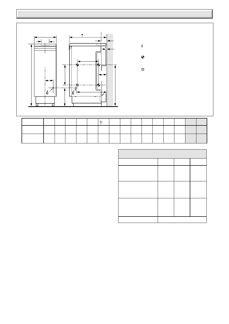
Diagram 1.1
GENERAL DIMENSIONS - given in millimetres (Approx. inches)
RANGE RATING
HIDEAWAY 50
NOMINAL
kW
HEAT INPUT
(GROSS)
Btu/h
15.06
16.80
18.64
51,400
57,300
63,600
min
medium
max
BURNER
mbar
SETTING
PRESSURE
in.w.g
(HOT)
9.3
11.6
13.9
3.7
4.6
5.6
NOMINAL
kW
HEAT
OUTPUT
Btu/h
11.72
13.19
14.65
40,000
45,000
50,000
205752
1 General
A
B
C
D
E
F
G
H
J
K
L
M
N
mm
300
118
598
294
265
533
3
300
445 121
88
900
115
in.
11
3
/
4
4
5
/
8
23
1
/
2
11
1
/
2
10
1
/
2
21
1
/
8
11
3
/
4
17
1
/
2
4
3
/
4
3
1
/
2
35
1
/
2
4
1
/
2
INJECTOR
Sheet Metal Parts
Warning. When installing or servicing this boiler care should be
taken when handling sheet metal parts, to avoid the possibility
of personal injury.
Important Notice
This boiler is for use only on G20 gas.
Wherever possible, all materials, appliances and components
to be used shall comply with the requirements of British
Standards.
Where no British Standards exist, materials and equipment
should be fit for their purpose and of suitable quality and
workmanship.
1.1 Data
Approx.weight of boiler: 76kg (168 lb)
Water content:
5.76litre (1.27 gal)
Gas connection:
Rc
1
/
2
(
1
/
2
BSP)
Water connection:
Rc1 (1inch BSP)
Electrical supply:
240V - 50Hz fused at 3A
Burner:
Aeromatic
The Seasonal Efficiency Domestic Boilers UK (SEDBUK) is
71.0%.
The value is used in the UK Government’s Standard Assessment
Procedure (SAP) for energy rating of dwellings. The test data
from which it has been calculated have been certified by B.S.I.
1.2 Range Rating
This boiler is range rated and may be adjusted to suit individual
systems. The table gives settings and outputs.
The boiler input is supplied preset to maximum and should be
adjusted to suit system requirements.
WATER CONNECTIONS
Rc1 (1in. B.S.P.T.)
✽
INSIDE DIAMETER OF
SOCKET FOR 100mm (4in.)
NOMINAL DIAMETER FLUE
TO BS567
WATER CONNECTIONS Rc1
reduced with DISTRIBUTOR
TUBE to Rc
3/
4
(
3/
4
in. B.S.P.T.)
(pumped return)
GAS CONNECTION
Rc
1/
2
(
1/
2
in. B.S.P.T.)
✝
A SPECIAL TOP CASING
TO SUIT 600mm (23
5/
8
in.)
WORKTOPS IS AVAILABLE
0993
F (MIN)
D
FLUE
C
E
B
C
L
A
M
C
L
L (MIN)
G
(MIN)
J (MIN)
H
N
*
FLUE
K
(MIN)
1.3 Statutory Requirements
The installation of this boiler must be carried out by a competent
person in accordance with the relevant requirements of the
current issue of:
Manufacturer’s instructions, supplied.
The Gas Safety (Installation and Use) Regulations, The Building
Regulations, Local Water Company Byelaws, The Building
Standards (Scotland) Regulations, applicable in Scotland, The
Health and Safety at Work Act, The Control of Substances
Hazardous to Health, The Electricity at Work Regulations and
any applicable local regulations.
Detailed recommendations are contained in the current issue of
the following British Standards and Codes of Practice:
BS6798, BS5440 Part 1 and 2, BS5449, BS6700, BS6891,
BS5546, BS7478, BS7593, BS7671.
Manufacturer’s instructions must not be taken as overriding
statutory requirements.
6
221808B
1 General
1.4 B.S.I. Certification
This boiler is certificated by B.S.I. for safety and performance.
It is, therefore, important that no alteration is made to the boiler
unless approved, in writing, by Hepworth Heating Ltd.
Any alteration not approved by Hepworth Heating Ltd., could
invalidate the B.S.I. certification, boiler warranty and could also
infringe the statutory requirements.
1.5 Gas Supply
The gas installation shall be in accordance with the current
issue of BS6891.
The supply from the governed meter must be of adequate size
to provide a steady inlet working pressure of 20mbar (8in wg) at
the boiler.
On completion test the gas installation using the pressure drop
method and suitable leak detection fluid, purge in accordance
with the current issue of BS6891.
1.6 Electrical
Warning. This boiler must be earthed.
The electrical installation must be carried out by a competent
person. All external components must be of the approved type
and must be connected in accordance with the current issue of
BS7671 and any local regulations which may apply.
Connection of the boiler and any system controls to the mains
supply should be through a 3A fused double pole isolating
switch, having a minimum double pole contact separation of
3mm, serving only the boiler and system controls.
Heat resistant flexible cable of at least 0.75mm
2
, to the current
issue of BS6500 Table 16 must be used for all connections
within the boiler casing.
1.7 Boiler Location
The boiler must not be installed in a room used or intended to
be used as sleeping accommodation or a room containing a
bath or shower.
This boiler is not suitable for installation out of doors.
The boiler must stand on a level floor, conforming with local
authority requirements and building regulations. The base
temperature is within the requirements of the current issue of
BS5258. The boiler may be stood on a wooden floor but a metal
plate is required to protect plastic tiles and similar floor coverings.
Suitable clearance needs to be available at the sides of the
boiler to ease connection of pipework. The actual clearances
will vary according to site conditions.
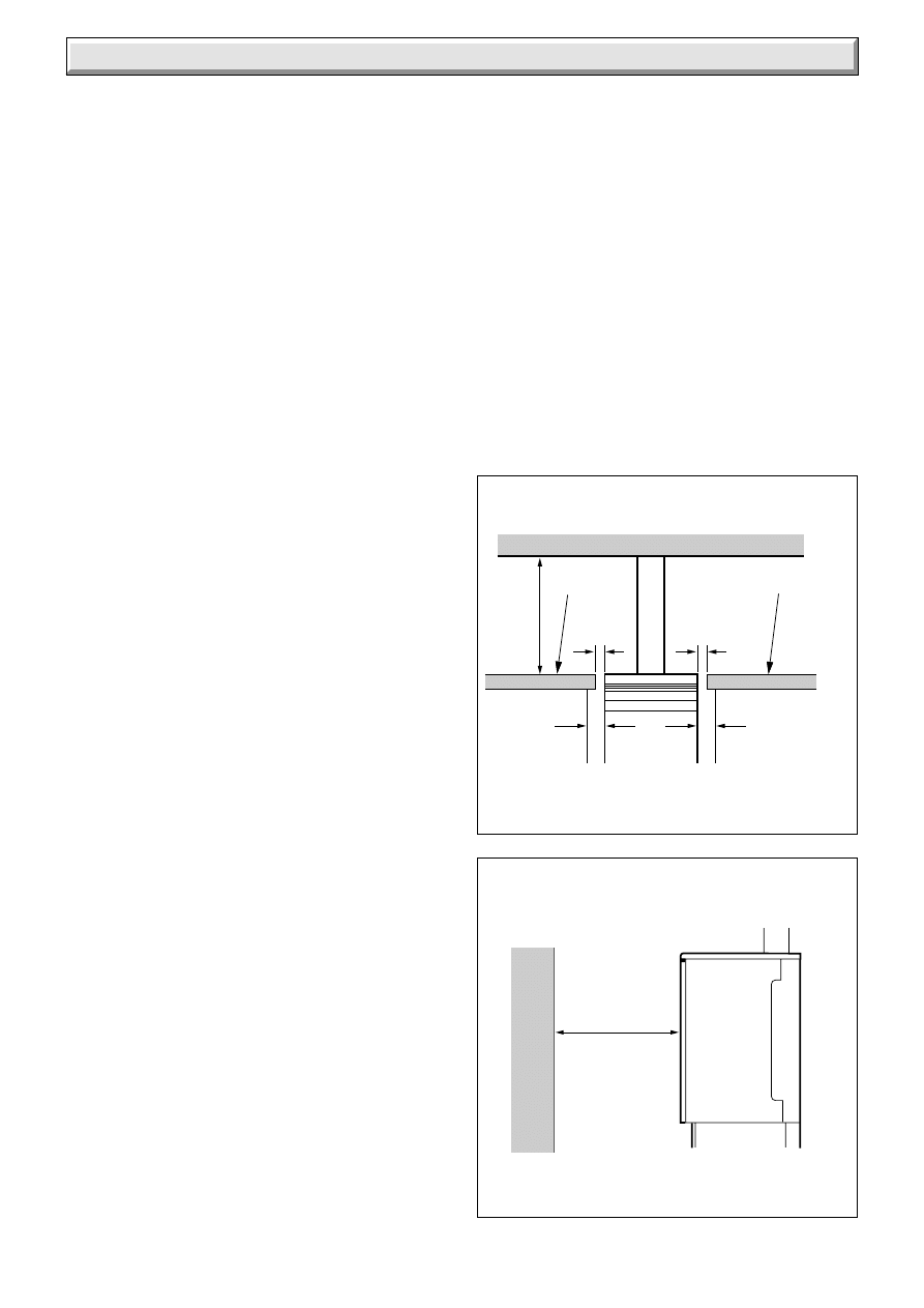
When the boiler is to be installed level with work surfaces,
minimum clearances to fixtures, walls and the like should be
provided, see diagram 1.2.
To ease minimum clearances it may be necessary to modify
units or fixtures.
A front access clearance should be provided as shown in
diagram 1.3.
The minimum gap behind the top casing is dimension “G” in
diagram1.1. The boiler can be sited further away from the wall
if required to align with kitchen units.
Combustible wall material must be 25mm (1in) away from flue
components.
A special top casing, part number 424858 can be bought, to
enable boiler casings to be arranged flush with 600mm (23
5
/
8
in)
deep worktops.
Where the installation of the boiler will be in an unusual location,
special procedures may be necessary, the current issue of
BS6798 gives detailed guidance on this aspect.
A compartment used to enclose the boiler must be designed
and constructed specifically for this purpose. An existing
cupboard or compartment modified for the purpose may be
used. Details of essential features of cupboard and compartment
design are given in the current issue of BS6798.
Make sure that nothing will obstruct the side clearances or side
grilles. If installing the boiler in a compartment make sure that
openings and vents are not obstructed.
1.8 Heating System Controls
The heating system should have installed: a programmer and
room thermostat controlling the boiler.
Thermostatic radiator valves may be installed in addition to the
room thermostat.
Note: For further information, see The Building Regulations
1991 - Conservation of fuel and power, 1995 edition - Appendix
G, table 4b.
TOP & SIDE CLEARANCES
Diagram 1.2
Diagram 1.3
FRONT CLEARANCE
530 (21in.)
WALL OR
FIXTURE
0911
BOILER
1020
6
(
1/
4
in.)
6
(
1/
4
in.)
254
(10 in.)
20 (
3/
4
in.)
CUPBOARD
CUPBOARD
BOILER
20 (
3/
4
in.)
WORKTOP
WORKTOP
7
221808B
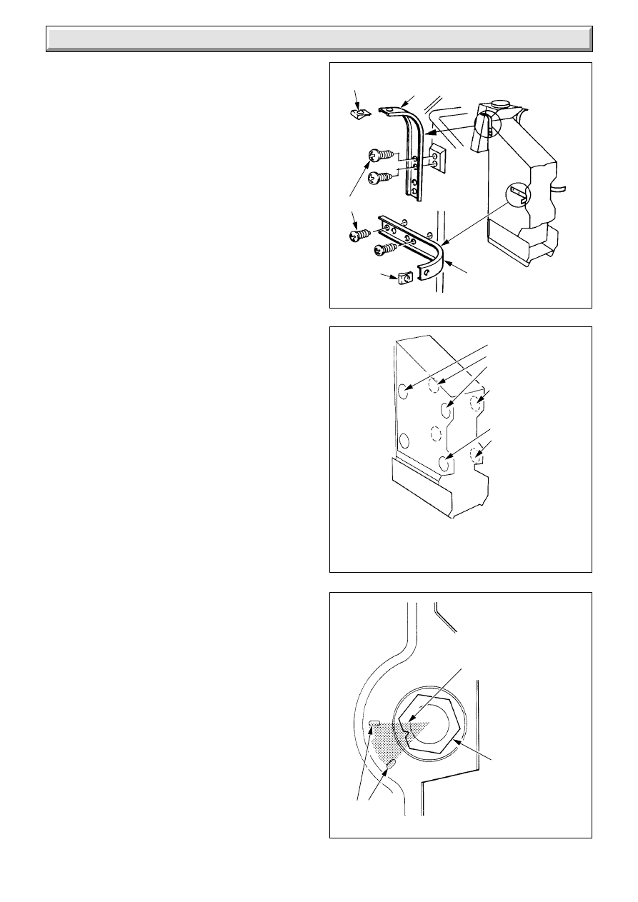
PRESSURE LOSS OF BOILER
Diagram 2.3
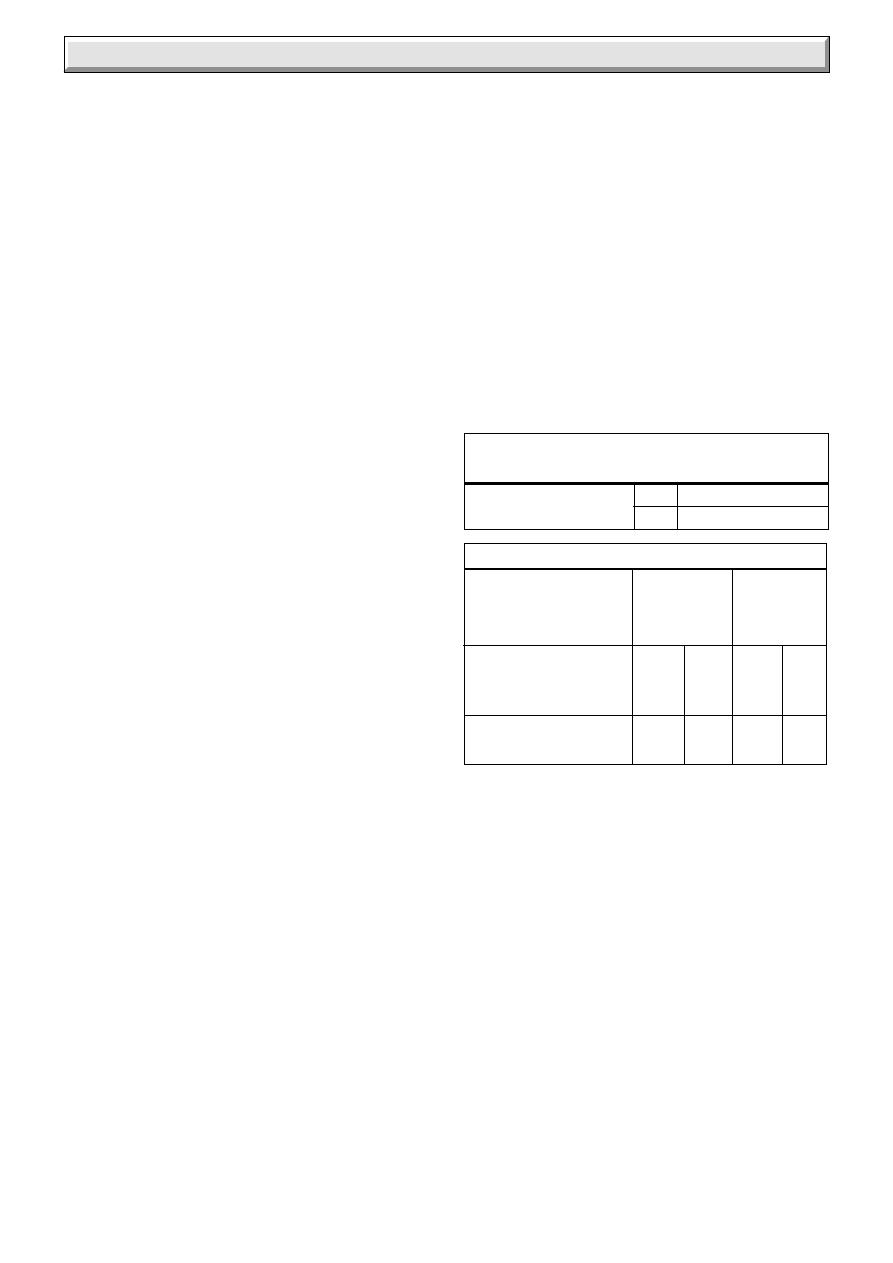
Diagram 2.2
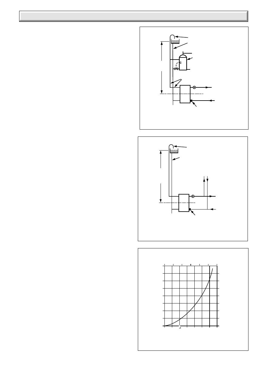
Diagram 2.1
FULLY PUMPED SYSTEM
(DIAGRAMMATIC)
0869
0870
0872
27metres
Max.
PUMP
To Heating
Circuit
INDIRECT
CYLINDER
(Shown with
recommended
thermostat and valve).
22mm VENT
15mm COLD FEED
REFER TO BS 5546
28mm
Distributor tube in
pumped return
connection
BOILER
CL
DRAIN OFF
COCK
PUMPED HEATING AND GRAVITY
DOMESTIC (DIAGRAMMATIC)
1 metre
MIN.
27metres
MAX.
PUMP
To Heating
Circuit
TO INDIRECT
CYLINDER
22mm VENT
15mm
COLD FEED
Distributor tube in
pumped return
connection
BOILER
CL
DRAIN OFF
COCK
600
500
400
300
200
100
0
12
8
4
0
0
4
8
12
16
20
24 28
FLOW RATE (LITRES/MINUTE)
WATER PRESSURE LOSS
(mm HEAD OF WATER)
WATER PRESSURE LOSS
(INCHES HEAD OF WATER)
24
16
800
32
28
20
700
0
1
2
3
4
5
6
FLOW RATE (GALLON/MINUTE)
2.1 Water Pressure Head
This boiler must not be connected to a sealed water system.
This boiler shall only be connected to an open vented cistern
water supply, with a minimum head of 1metre (39in) and a
maximum of 27metre (90ft).
2.2 Inhibitor
Attention is drawn to the current issue of BS5449 and BS7593
on the use of inhibitors in central heating systems.
If an inhibitor is to be used in the system contact should be made
with a manufacturer so that they can recommend their most
suitable product.
If using in an existing system take special care to drain the entire
system, including the radiators, then thoroughly cleaning out
before fitting the boiler, whether or not adding an inhibitor.
2.3 Gravity Domestic Hot Water and Pumped
Central Heating
It is recommended that a cylinder thermostat is used to prevent
the stored water temperature becoming too high when the
heating pump is off.
The domestic hot water primary flow and return must be 28mm
od. The installation must comply with the current issue of
BS5546 and BS6700, see diagram 2.1.
If the above conditions cannot be met, it is suggested that a fully
pumped system is used.
2.4 Pumped Central Heating and Domestic Hot
Water
Where a single flow and return is taken from the boiler, a
minimum static head of 1metre (39in) must be provided between
the water level in the cold water cistern and the centre of the
waterway, see diagram 2.2.
2.5 Circulation Pump
Normally the pump should be set to give a temperature difference
of 11
o
C
(20
o
F), across the boiler. At the appropriate flow rate the
resistance through the boiler can be found by reference to the
pressure loss graph, diagram 2.3.
Use a pump with integral valves or fit valves as close to the
pump as possible.
2.6 Domestic Hot Water Cylinder
For all systems supplying domestic hot water the cylinder must
be indirect.
2.7 Safety Valve
A safety valve need not be fitted to an open vented system.
2.8 Draining Tap
A drain tap must be fitted at the lowest points of the system
which will allow the draining of the entire system, including the
boiler and domestic hot water cylinder.
2 Water Systems
8
221808B
Important Note
The boiler is fitted with a Flue Blockage Safety Device, which
will shut down the boiler if there is an unacceptable spillage of
products at the draught diverter.
This safety device MUST NOT under any circumstances be
interferred with or put out of action. The safety device must only
be replaced with the Glow-worm parts.
3.1 Flue
The integral draught diverter on the Hideaway range of boilers
makes the combustion performance independent of conditions
in the secondary flue, but in common with other fuels an efficient
flue is necessary to make sure of a trouble free installation.
The flue must be at least equivalent to 1m vertical.
The boiler flue socket is designed to take flue pipes to the
current issue of BS567. If a flue pipe to BS715 is to be used, an
adapter must be fitted to the boiler flue socket, as diagram 1.1.
The flue must be in accordance with the current issue of
BS5440 Part 1.
3.2 Flue Guidelines
The flue should be kept as short as possible. Horizontal or very
shallow runs of the flue should be avoided as they encourage
local cooling.
Always choose a flue route which will cause the least cooling of
the flue.
There should be a vertical rise of at least 600mm (2ft) before
using a bend. 90
o
elbows should not be used.
End with a certificated flue terminal, preferably above ridge
height, but at least above the eaves of a pitched roof.
An existing chimney must be thoroughly swept and all debris
cleared away before lining.
3.3 Timber Frame Buildings
If the boiler is to be installed in a timber frame building it should
be fitted in accordance with the Institute of Gas Engineers
document IGE/UP/7/1998. If in doubt seek advice from the local
gas undertaking or Hepworth Heating Ltd.
3.4 Ventilation for Boiler Installed in a Room
or Space
If the boiler is to be installed in a room or space a purpose
designed permanent ventilation opening, to supply air for
combustion, must be provided on an outside wall to external air,
refer to the current issue of BS5440 Part 2 for details.
The opening may be directly into the room or the space
containing the boiler, or an outside wall of an adjacent room or
space which has an internal permanent air vent, of the same
size, into the room or space containing the boiler.
Do not ventilate through a bedroom, bedsitting room, private
garage or a room containing a bath or shower.
When the boiler is installed in a room or internal space already
containing other fuel burning appliances then the air supply of
such appliances must be taken into account.
The ventilation opening areas are given in “Air Vent Table A”.
The figures quoted refer to the minimum acceptable effective
area.
3 Flue and Ventilation
3.5 Ventilation for Boilers Installed in a
Cupboard or Compartment
When the boiler is fitted in a cupboard or compartment, high and
low level purpose designed, permanent openings must be
provided to supply air for combustion and compartment
ventilation.
The air vents must have minimum areas in accordance with
“Compartment Air Vent B”. The figures quoted refer to the
minimum acceptable effective area.
Both the high and low level openings must communicate with
the same room, or must both be on the same wall to outside air.
If air vent grilles are fitted to a cavity wall, the opening through
the wall must be ducted.
Where ventilation air to a compartment is taken from a room or
space, then the room or space must be fitted with a ventilation
opening as specified in “Air Vent Table A”.
For information regarding compartment requirements refer to
the appropriate section of the current issue of BS6798.
3.6 Extract Fans
If an extract fan is fitted in the premises, there is a possibility that
if adequate inlet openings are not provided, spillage of the
products from the boiler could occur.
When openings are fitted in accordance with the current issue
of BS5440 Part 2 and this section, extract fans should not cause
down draught, but where such fan installations are found, a
spillage test must be carried out in accordance with the current
issue of BS5440 Part 1 and any corrective work done.
FROM
OUTSIDE
COMPARTMENT AIR VENT TABLE 'B'
COMPARTMENT
VENTILATION
REQUIREMENTS
172cm
2
26in
2
344cm
2
52in
2
86cm
2
13in
2
172cm
2
26in
2
VENTILATION
FROM ROOM
OR SPACE
HIGH LEVEL
LOW LEVEL
VENT AREA
VENT AREA
AIR VENT TABLE 'A' FOR
ROOM/SPACE INSTALLATIONS
EFFECTIVE
AREA OF VENT
cm
2
in
2
55
8
9
221808B
4 Installation
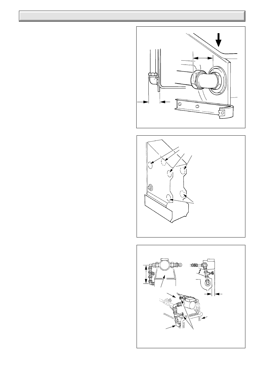
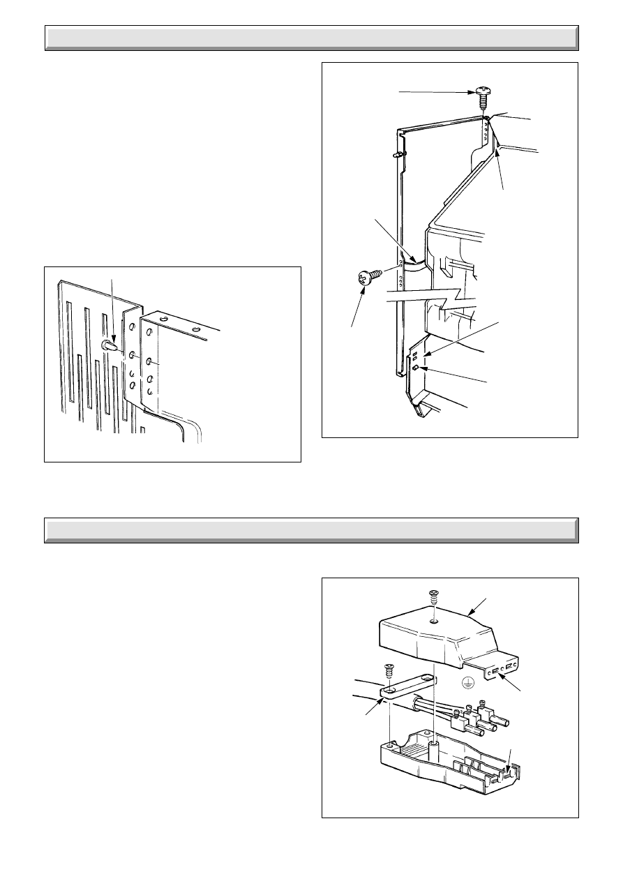
CASING BRACKETS FITTING
Diagram 4.1
1000
CAPTIVE
NUT
CASING
BRACKET
CAPTIVE
NUT
CASING
BRACKET
No.8 SCREW (8)
Before fitting the boiler make sure the location selected is in
accordance with the requirements of Section 1.7.
4.1 Unpacking
The boiler casing panels are packed separately within the main
case. They are designed to enable the gas and water connections
to be made before fitting the casing panels.
The main casing brackets, distributor tube and loose items, in a
plastic bag, are packed in the top fitment.
4.2 Casing Brackets
Fit the four casing brackets as shown in diagram 4.1, using eight
No.8 screws.
Push the captive nuts, supplied loose, on to the casing brackets
as shown in diagram 4.1.
4.3 Water Connections - Gravity Domestic Hot
Water and Pumped Heating
Fit suitable fittings into the boiler tappings, see diagram 4.2.
Connect pipework into prepared fittings, making sure that all
pipes are taken backwards and will clear the casings, see
diagram 1.1.
Heating flow, any one connection of the upper connections may
be used.
Gravity domestic hot water flow, any one connection of the
remaining upper connections may be used.
Heating return, the distributor tube MUST be fitted into either
one of the front lower connections on ALL installations, see
diagram 4.3. The distributor tube is packed in the top carton
fitment.
Gravity domestic hot water return, any one connection of the
three remaining lower connections may be used.
When the front connections are used it is essential that any
pipework or fittings do not stick out more than the amount shown
in diagram 4.4.
If limited space only is available, it is recommended that the front
connections are used.
Fit plugs into unused tappings.
Do not route any pipes across the front of the boiler thermostat
pocket, controls or the combustion chamber cover.
Pipework must not be routed directly below the draught diverter,
across the boiler, but may be routed under the edges of the
draught diverter.
4.4 Water Connections - Fully Pumped
Systems
It is important that all connections are made as shown in
diagram 4.5.
Fit suitable fittings into the boiler tappings as required, see
diagram 4.5.
The water distributor tube MUST be fitted into the return
connection, see diagram 4.3. The distributor tube is packed in
the top fitment.
Connect pipework into prepared fittings making sure that all
pipes are taken backwards and will clear the casings, see
diagram 1.1.
When the front connections are used it is essential that any
pipework or fittings do not stick out more than as shown in
diagram 4.4.
If only limited space is available, it is recommended that the front
connections are used.
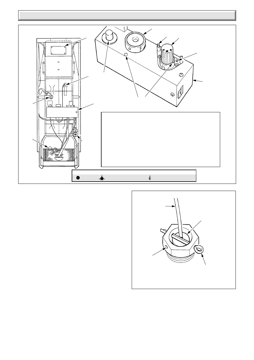
DISTRIBUTOR TUBE
Diagram 4.3
Diagram 4.2
WATER CONNECTIONS - GRAVITY
DOMESTIC, PUMPED HEATING
ALTERNATIVE
HEATING
RETURN
With distributor
tube (not shown)
ALTERNATIVE
HEATING OR
DOMESTIC
HOT WATER
FLOW
GRAVITY
DOMESTIC
RETURN TO
ANY OF THE
3 REMAINING
LOWER CONNECTIONS
0873
0871
DISTRIBUTOR
TUBE
must be in
pumped return
connection
Notch on
DISTRIBUTOR must
lie within the shaded
area, BETWEEN
TWO MARKERS
MARKERS
10
221808B
Fit plugs into all unused tappings.
Do not route any pipes across the front of the boiler thermostat
pocket, controls or combustion chamber cover.
Pipework must not be routed directly below the draught diverter
across the boiler, but is allowed to be routed under the edges of
the draught diverter.
4.5 Pump in Boiler Casing
If the pump is to be fitted inside the boiler casing, position it as
shown in diagram 4.6 to either of the front connections.
There must be sufficient clearance “X” between the pump body
and the cleaning door to allow for removal of the door for flueway
cleaning.
4.6 Gas Connection
Do not route the gas supply across the combustion chamber or
burner feed pipe. The gas feed must be along the right hand
side of the boiler.
Make the gas connection to the gas service cock.
4.7 Flue Connection
The flue should be 100mm (4in) nominal diameter, refer to
Section 3 and diagram 1.1.
Fix and seal the flue to the hood in accordance with normal
practice.
Diagram 4.6
Diagram 4.5
WATER CONNECTIONS FULLY
PUMPED SYSTEMS
PUMP CLEARANCES
0874
ALTERNATIVE
FLOW
POSITIONS
ALTERNATIVE
RETURN
POSITIONS
With distributor
tube (not shown)
Clearance 'X' must be left to enable cleaning
door removal and boiler servicing
'X'
FLUEWAY
CLEANING
DOOR
ALTERNATIVE
R.H. FLOW
CONNECTION
ISOLATING
VALVES
L.H. FLOW
CONNECTION
175
(7)
35 (1
3
/
8
)
0875
Diagram 4.4
PIPEWORK
CASING CLEARANCES
VIEW ON ARROW 'A'
1524
'A'
57 MAX.
(2
1
/
4
in.)
BOILER
57 MAX.
(2
1
/
4
in.)
4 Installation
11
221808B
MAINS INLET CONNECTOR
Diagram 6.1
0878
N E
L
COVER
CABLE
CLAMP
LUGS
SLOTS
SIDE CASINGS FITTING
Diagram 5.2
1018
LOCATING
LUG AND
SLOT
No. 8
SCREW (2)
No. 8
SCREW (2)
CASING
BRACKET
CASING
BRACKET
BOILER
PLINTH
5 Casing Location / Fitting
5.1 Side Vent Grille
One vent grille is supplied with the boiler which can be fitted at
the rear of the left or right hand side casing. The grille is fitted
on the opposite side to any pipework connections.
Fit the grille, if required, to the side panel as shown in diagram
5.1 prior to fixing the side panel. The plastic pegs are a tight fit
and are best pushed home with a flat faced tool.
Do not use the grille if water connections are on both sides of the
boiler or if the boiler is screened by fixtures.
5.2 Side Casings
Fit side casing by locating their lugs into the lower slots in the
base tray, see diagram 5.2.
Secure the casing sides to the casing bracket at the front top.
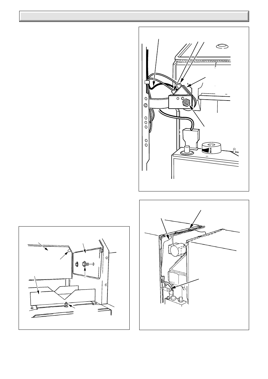
6.1 Control Box Cable Connection
Remove the screw and cover from the mains inlet connector,
see diagram 6.1.
Using heat resistant flexible cable of suitable length and rating,
as Section 1.6, connect the cable to the terminals in the
connector. Secure the outer sheathing with the clamp.
Engage slots and lugs, replace connector cover and secure
with screw.
Connect mains inlet connector to the control box and use three
of the cable clips, supplied loose, pushed on to the edge of the
left hand panel in positions “CB” as shown in diagram 6.2 to
make sure that the cable does not touch any hot surfaces.
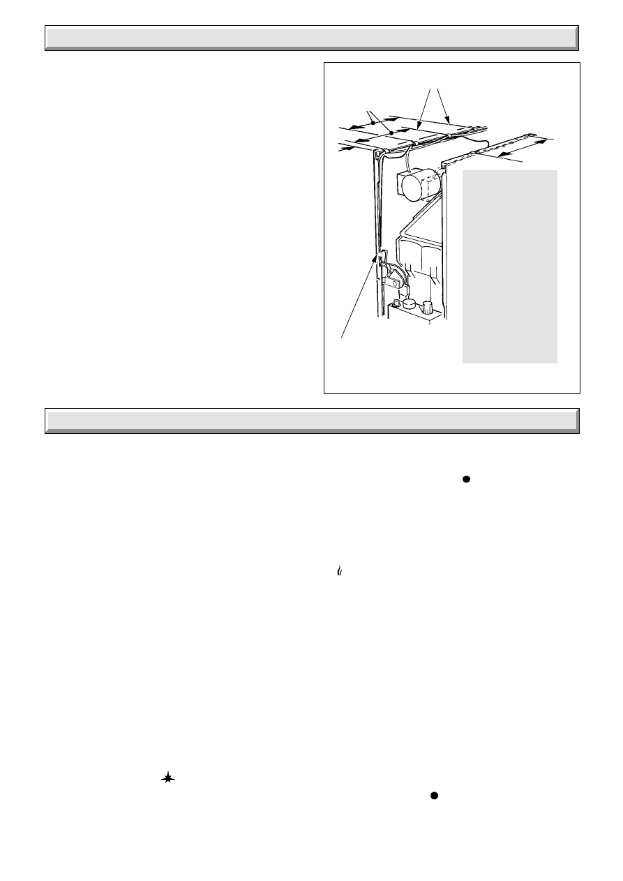
6.2 Circulation Pump Cable Connection
Heat resistant cable with a rating as stated in Section 1.6 must
be used for all wiring near the boiler, including the pump, if within
the boiler casing.
Support the pump cable away from hot surfaces if within the
boiler casing by pushing two cable clips, supplied loose, on to
the top edge of one side casing, as shown as “P” or “AP” in
diagram 6.2.
6 Electrical Wiring
SIDE VENT GRILLE
Diagram 5.1
SIDE VENT GRILLE
(If required, will fit to
left or right side casing)
PLASTIC PEG
SIDE CASING
(R.H. SHOWN)
0885
12
221808B
6.3 Flue Blockage Safety Device - Capillary
and Interrupter Electrical Leads
For transit the capillary is taped to the side of the boiler.
Remove tape and place capillary into cable clips provided, see
diagram 6.2.
Note: Capillary must not touch the heat exchanger side.
Secure the interrupter electrical leads so as not to strain them,
see diagram 6.2.
6.4 System Controls
The electrical installation must be in accordance with the
current issue of BS7671.
The electrical isolator must isolate both the boiler and system
controls.
6.5 Testing
Checks to ensure electrical safety should be carried out by a
competent person.
In the event of an electrical fault after installation of the boiler,
preliminary system checks must be carried out, that is, earth
continuity, polarity and resistance to earth as described in a
multimeter instruction book.
6 Electrical Wiring
CABLE CLIP POSITIONS
Diagram 6.2
AP
AP
P
CB
P
CB
25
(1)
230 (9)
230 (9)
Fit 2 pump cable
clips at positions P.
Fit 3 control
box feed cable
clips at
positions CB.
Alternative pump
cable clips
(if feed is on the
left hand side) at
positions AP.
SAFETY DEVICE CAPILLARY
CLIP POSITION
0904
INTERRUPTER
ELECTRICAL
LEADS CLIP
CB
7 Commissioning
Please ensure the “Benchmark” logbook is completed and left
with the user.
7.1 Commissioning and Testing the Boiler
The whole of the system should be thoroughly flushed out with
cold water with pump removed. Make sure that all valves are
open. Refit the pump and fill the system. Examine for water
soundness and vent all air from the system, including the pump.
Caution. The following should be done by a competent person.
Identify the controls, refer to diagram 7.1.
Check that the gas cock “K” is closed, that is, slot is horizontal.
Open all windows and put out any naked lights, pipes or
cigarettes.
Purge air from the gas supply in accordance with the current
issue of BS6891.
Carefully unwind the thermostat capillary, insert the phial fully
into pocket “J” and secure the location washer behind the
retaining split pin, supplied in the loose items pack, see diagram
7.2.
Check that the mains electrical supply is switched off.
Set thermostat control knob “B” to “O”.
Remove gas test pressure point screw “G” and fit a suitable
pressure gauge.
Open gas cock “K”, slot vertical.
Note: Make sure the Flue Blockage Safety Device reset button
'N' is fully pushed in.
Turn gas control knob “A” to '
' , the pilot and ignition position
and push in. At the same time press and release the ignition
button “C” until the pilot lights. At this stage air may be present
in the gas supply pipes and this operation may need to be
repeated. When the pilot burner lights, keep control knob “A”
fully pushed in for about 15 seconds. If the pilot fails to remain
alight, repeat lighting procedure, but now keep the control
button pushed in for a little longer.
If the control knob “A” is turned to ' ', a safety device prevents
relighting in an unsafe condition. No attempt should be made
to push knob “A” in until 3 minutes have gone by.
Note: Should the boiler fail to operate correctly refer to the Fault
Finding - Section 10.
Make sure that the pilot is alight and stable, see diagram 7.3 for
flame length, switch on the electrical supply. Set any remote
controls so that they are calling for heat. Turn control knob “A”
to ' ' main burner position. Set boiler thermostat control knob
“B” between “MIN” and “MAX” against the setting point on the
control box, the main burner will light. “MAX” is about 82
o
C
(180
o
F).
Test for gas soundness around boiler gas components with a
suitable leak detection fluid.
Set the burner gas pressure required, ten minutes after lighting,
see Data label “L” for settings or refer to Section 1.2. Adjust
screw “F”, diagram 7.1 to obtain the required heat input. Turn
clockwise to decrease. After adjusting, seal the screw.
If any doubt exists, the gas rate should also be checked at the
meter. This should be in the range of:
Hideaway - 50 - 1.8 to 2.2m
3
/h 51 to 63ft
3
/h
The rates are for guidance only, depending on the heat setting.
Stick the self adhesive arrow on to the data label against the
output the boiler is set to. The arrow is in the loose items pack.
Check the operation of the flame failure device as follows:
With the main burner alight, turn the gas control valve knob “A”
fully clockwise to its stop ' ', the main and pilot flames will go
out. Relighting will not now be possible. Before 60 seconds the
safety device will work, indicated by a “click” from the gas valve.
13
221808B
7 Commissioning
Diagram 7.2
SECURING THE
THERMOSTAT PHIAL
1870
THERMOSTAT
CAPILLARY
LOCATION
WASHER
PHIAL
POCKET
RETAINING
SPLIT PIN
Do not attempt to relight until three minutes have gone by.
Remove the pressure gauge and refit the pressure test point
screw “G”, makes sure a gas tight seal is made.
Turn thermostat “B” to “O” and relight the pilot burner as above.
Relight the main burner as above.
Check that the boiler thermostat and all remote controls are
working correctly.
Do not attempt to adjust the thermostat calibration screw.
Test the boiler for spillage of the flue products at the draught
diverter as detailed in the current issue of BS5440 Part 1. If an
extract fan is fitted in the premises, refer to Section 3.6.
7.2 Commissioning the System
Allow the system to warm up and set the pump adjuster to a
design position which gives the correct temperature difference
of 11
o
C (20
o
F) between the flow and return. There should be no
undue noise in the system, pumping over or entry of air at the
open vent above the cold water feed and expansion cistern.
Allow the system to reach maximum working temperature and
examine for water soundness.
The system should then be drained down as rapidly as possible
to complete the flushing process.
The system should then be refilled, vented and examined for
water soundness.
Diagram 7.1
BOILER COMPONENTS
1005
J
H
L
C
A
G
F
H
SETTING
POINTS
E
N
K
(Shown
closed)
POSITIONS:-
A GAS CONTROL KNOB.
J PHIAL POCKET.
B TERMOSTAT CONTROL.
K GAS SERVICE COCK.
C PIEZO IGNITION BUTTON.
L DATA BADGE.
E VIEWING WINDOW.
N FLUE
F BURNER GAS RATE
BLOCKAGE
GAS CONTROL KNOB 'A'
SAFETY DEVICE
ADJUSTMENT.
RESET BUTTON.
G BURNER PRESSURE
TEST POINT.
H CONTROL BOX.
= OFF
= PILOT/IGNITION
= MAIN BURNER
B
14
221808B
7 Commissioning
FLAME DIMENSION
Diagram 7.3
1009
13 (
1
/
2
in.)
APPROX.
FLAME
DIMENSION
VIEWING
WINDOW
PILOT
BURNER
ASSEMBLY
7.3 Completion
Instruct and demonstrate the efficient and safer operation of the
boiler, heating and domestic hot water system.
Hand the Instructions for Use to the user, for them to keep,
making sure that they fully understand them.
Advise the user that to ensure the continued efficient and safe
operation of the boiler is recommended that it is checked and
serviced at regular intervals. The frequency of servicing will
depend upon the particular installation and usage, but in general
once a year should be enough.
Draw attention, if applicable, to the current issue of the Gas
Safety (Installation and Use) Regulations, Section 35, which
imposes a duty of care on all persons who let out any property
containing a gas appliance.
It is the law that servicing is carried out by a competent person.
Advise that the boiler is fitted with a Flue Blockage Safety
Device and refer to the Instructions for Use.
Reminder - Leave these instructions and the “Benchmark”
logbook with the user.
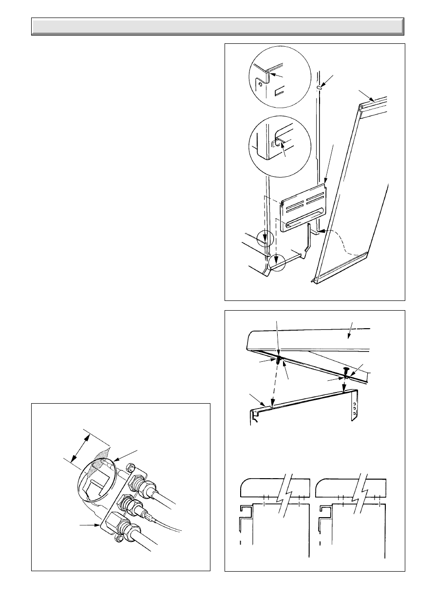
Fit the plinth front, by locating the sides over the boiler plinth
then lowering to engage the upper and lower hooks, see
diagram 7.4.
Fit four plastic pegs into the required holes in the top panel, see
diagram 7.5. The plastic pegs are a tight fit and are best pushed
home with a flat faced tool.
Push the casing top on to all four side panel locations. From
inside the casing check that all the rivets have engaged into the
holes.
Fit the door by locating the hooked runner at the bottom into the
slots in side casings and pushing on to the studs on the side
casings, see diagram 7.4.
PLINTH / DOOR FITTING
Diagram 7.4
TOP CASING FITTING
Diagram 7.5
0887
UPPER
HOOK
VIEW 1
VIEW 2
STUD
PLINTH
FRONT
LOWER
HOOK
VIEW 1
VIEW 2
1180
PEG POSITIONS IN TOP CASING
A = FRONT EDGE FLUSH
B = 10mm (
3
/
8
in) FRONT OVERHANG
TOP CASING
PLASTIC PEG (4)
B
A
SIDE
CASING
(L.H.)
A
B
SIDE
CASING
SIDE
CASING
DOOR
DOOR
AB
AB
AB
AB
DOOR
FASCIA
15
221808B
8 Servicing
Diagram 8.1
Diagram 8.2
ACCESS FOR SERVICING
Diagram 8.3
SECURING THE
THERMOSTAT PHIAL
ISOLATION OF
GAS AND ELECTRICITY
0907
1870
LOCATION
WASHER
PHIAL
POCKET
RETAINING
SPLIT PIN
1010
Servicing must be carried out by a competent person.
Before servicing, turn off the gas supply at the boiler service
cock, see diagram 8.1 and isolate the electrical supply to the
boiler.
Always test for gas soundness after completing a service and
replacement of parts.
8.1 Boiler Flueways
Pull door forwards at the top to disengage the studs and lift to
release from slots, see diagram 7.4.
Lift plinth front up and forwards to withdraw, see diagram 7.4.
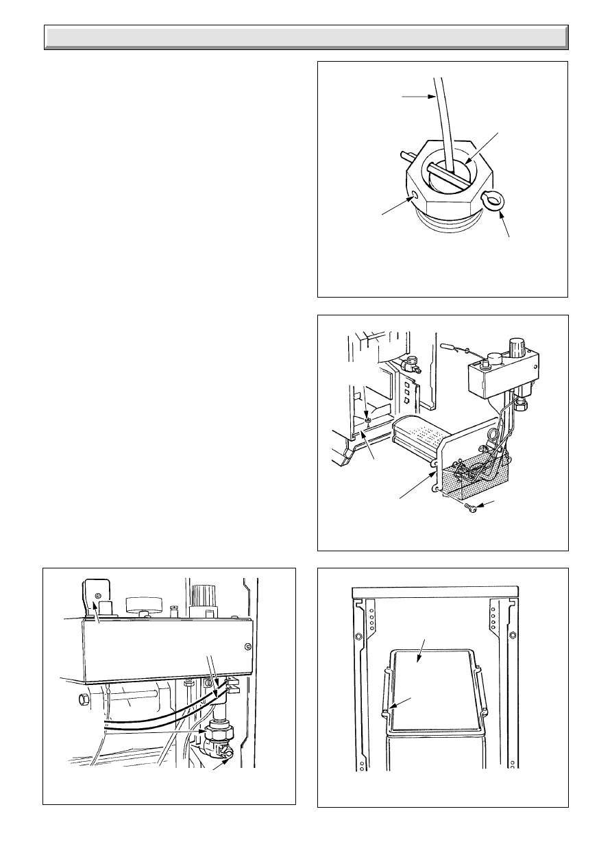
Disconnect the union on the gas service cock, see diagram 8.1.
Remove the mains inlet connector by pulling upwards, see
diagram 8.1.
Withdraw the retaining split pin from the thermostat phial pocket
then withdraw the phial and capillary, see diagram 8.2.
Remove electrical connections from the interrupter, see diagram
8.1.
Remove the four screws retaining the combustion chamber
cover and burner assembly, see diagram 8.3. Withdraw
forwards the complete assembly of cover, control box and
burner.
Remove the graphite coated nut to release baffle tray and
remove the combustion chamber, taking care not to damage
the insulation material on the sides.
Remove the self-tapping screws which retain the cleaning door
and lift clear, see diagram 8.4.
Place a sheet of paper in the combustion chamber to catch any
flue debris.
Remove flueway baffles, see diagrams 8.7 and 8.8.
Thoroughly clean boiler flueways and fins with a suitable stiff
brush.
Replace in reverse order, after completing instructions in
Section 8.2 and 8.3.
Make sure that the thermocouple phial is at the bottom of its
pocket and located by the washer being behind the retaining
split pin, leaving clearance between the capillary tube and
boiler, see diagram 8.2.
GRAPHITE
COATED
NUT
SECURING
SCREW (4)
COMBUSTION
CHAMBER COVER
BAFFLE
TRAY
GAS
SERVICE
COCK
UNION
MAINS INLET
CONNECTOR
(pull upwards)
INTERRUPTER
ELECTRICAL
CONNECTIONS
THERMOSTAT
CAPILLARY
TURN OFF
ACCESS TO FLUEWAY
Diagram 8.4
0908
FLUEWAY
CLEANING
DOOR
SELF-
TAPPING
SCREW (4)
16
221808B
REMOVAL OF BURNER FROM
COMBUSTION CHAMBER
8 Servicing
Diagram 8.5
BURNER SERVICING
Diagram 8.6
1033
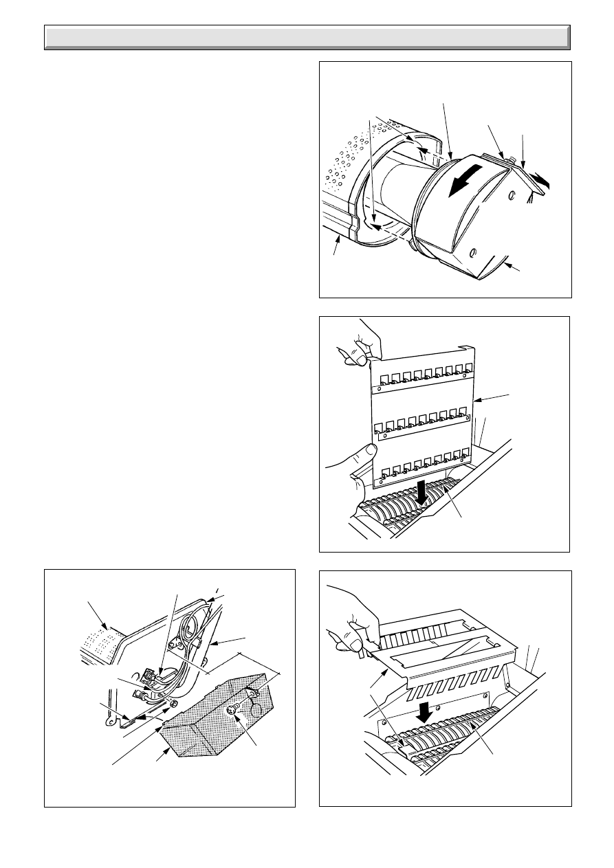
8.2 Burner and Injector
Follow instructions to remove the front cover, burner and controls
assembly as Section 8.1.
Remove the screw securing the lint arrester gauze to the
combustion chamber cover. Remove arrester by lifting slightly
and withdrawing forwards to clear gas pipe, thermocouple and
pilot tube, see diagram 8.5.
Remove the two burner securing nuts from the flange of the
burner supply pipe.
Remove the burner from the cover and supply pipe flange.
Slacken the nut securing the locking slide on the venturi right
side, disengage the slide to enable the venturi end of the burner
to be twisted anticlockwise to disengage it from the burner body,
see diagram 8.6.
Clean the burner parts and lint arrester thoroughly, using a
vacuum cleaner.
Check the condition of the burner gasket. Reuse or replace the
gasket as necessary. Reassembly by locating the venturi lugs
into the burner slots and twisting clockwise, see diagram 8.6.
Check the main burner injector for blockage or damage and
replace as necessary, see Section 9.2.
When replacing lint arrester locate the two lugs into the slots on
the combustion chamber cover and locate around the feed pipe,
then secure with the screws.
8.3 Service Checks
Inspect the pilot burner, thermocouple and pilot burner, cleaning
as necessary. Check the condition of the parts. If necessary
remove the pilot shield by removing the securing screw and nut.
Check the condition of the side and rear insulation panels in the
combustion chamber.
Check the condition of the seals on the cleaning door and the
combustion chamber cover.
Replace all items in the reverse order, relight and test the boiler.
Replacement of parts should be carried out by a competent
person.
SECURING
SCREW
LINT
ARRESTER
LUG
SECURING
NUT(2)
PROTECTIVE
SLEEVING
SLOT
MAIN
BURNER
INJECTOR
COMBUSTION
CHAMBER
COVER
1013
BURNER
SUPPLY
PIPE
Locate venturi
lugs in burner
slots and twist
clockwise to
engage
BURNER
BODY
BURNER
GASKET
NUT
LOCKING
SLIDE
VENTURI
Twist VENTURI
anti-clockwise
to disengage
from BURNER
BODY
Diagram 8.8
6126
BAFFLES
HEAT
EXCHANGERS
HEAT EXCHANGERS
Diagram 8.7
6122
BAFFLE
17
221808B
9 Replacement of Parts
Diagram 9.1
CONTROL BOX
6123
MAINS INLET
CONNECTOR
(Disconnect)
THERMOSTAT
CONTROL
KNOB
PIEZO
UNIT
ELECTRICAL
CONNECTORS
SLOT
IGNITION LEAD
(BLACK END)
BURNER
SUPPLY
PIPE
THERMOCOUPLE
HOOK
CONTROL BOX
COVER
COVER
SECURING
SCREW
GAS
VALVE
GAS VALVE
SECURING SCREW
ELECTRICAL
CONNECTORS
GAS VALVE
SECURING
SCREW
Before removing or replacing any parts, turn off the gas supply
at the boiler service cock, see diagram 8.1. Isolate the electrical
supply to the boiler.
Unless stated otherwise all parts are replaced in the reverse
order to removal.
Always test for gas soundness after replacing parts.
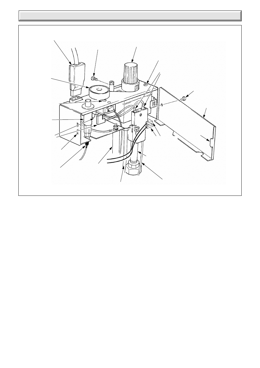
9.1 Gas Valve
Follow the relevant instructions in Section 8.1.
Remove control box cover by removing the screw and unhooking
at the side, see diagram 9.1.
Disconnect thermocouple nut, interrupter, electrical connections
and pilot tube connection at the gas valve.
Remove the two screws which secure gas valve to the control
box.
Tilt control box to enable it to be lifted off the gas valve.
Unscrew half union pipe from gas valve.
Unscrew the gas valve from the burner supply pipe.
When screwing the pipes into the new gas valve use a little
jointing compound on the external thread only, to make a gas
tight seal.
Replace thermostat phial as relevant part of Section 8.1.
Refer to diagram 9.2 to connect electrical leads.
It will be necessary to purge the system of air after changing the
gas valve. Follow the instructions in Section 7.1.
PILOT TUBE
HALF UNION
PIPE
THERMOSTAT
SECURING
SCREW (2)
INTERRUPTER
ELECTRICAL
CONNECTIONS
9.2 Boiler Thermostat
Follow the relevant instructions in Section 8.1 and 9.1.
Pull off the thermostat control knob.
Remove the two screws which secure the boiler thermostat to
the control box, see diagram 9.1.
Tilt the thermostat so that the electrical connections can be
removed.
Withdraw boiler thermostat from control box complete with
capillary tube and phial.
Refer to diagram 9.2 to connect electrical connectors.
Replace the thermostat phial as the relevant part of Section 8.1.
9.3 Piezo Unit
Pull door forward at the top to disengage the studs and lift to
release from slots, see diagram 7.4.
Remove mains inlet connector by pulling upward, see diagram
8.1.
Remove the control box cover by removing screw and unhooking
from slot at the side, see diagram 9.1.
Disconnect the ignition lead at the piezo unit.
Remove the nut inside the control box and remove piezo unit.
18
221808B
9 Replacement of Parts
PILOT ASSEMBLY
Diagram 9.3
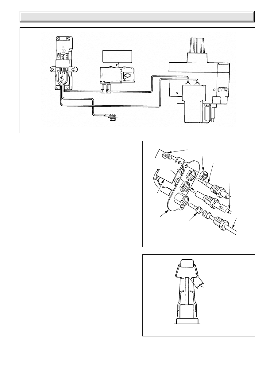
Diagram 9.2
CONTROL BOX WIRING
6124
240V~ 50Hz MAINS SUPPLY FUSED AT 3A
THERMOSTAT
L
N
C N/C
GREEN / YELLOW
RED
ORANGE
BLUE
CHASSIS EARTH
GAS
VALVE
0935
PILOT
TUBE
SPARK
ELECTRODE
IGNITION LEAD
(CLEAR END)
PILOT
INJECTOR
PILOT
BURNER
ASSEMBLY
PILOT
SHIELD
SECURING SCREW (2)
AND NUT (2)
THERMOCOUPLE
9.4 Thermocouple
Remove the door and plinth from the front as relevant parts of
Section 8.1.
Remove lint arrester as in Section 8.2.
Disconnect the thermocouple by unscrewing nuts at the gas
valve and pilot burner, see diagram 9.1 and 9.3. Release cable
clips and the thermocouple can be withdrawn.
Do not tighten nut at gas valve more than a quarter turn beyond
finger tight.
Replace lint arrester as Section 8.2.
9.5 Spark Electrode
Remove the door plinth as the relevant part of
Section 8.2.
Remove the lint arrester as Section 8.2.
Disconnect the ignition lead, see diagram 9.3.
Disconnect the thermocouple nut and withdraw the thermocouple
from the pilot burner.
Disconnect the nut retaining the spark electrode.
The spark gap dimension is shown on diagram 9.4.
9.6 Ignition Lead
Remove the door and plinth as the relevant parts of Section 8.1.
Remove the lint arrester as in Section 8.2.
Disconnect the ignition lead at the piezo unit, see diagram 9.1.
Disconnect ignition lead at the spark electrode, see diagram
9.3.
When reconnecting the lead, make sure that the clear end is
fitted to the spark electrode and the protective sleeve is fitted
where the lead passes through the lint arrester, see diagram
8.5.
SPARK GAP DIMENSIONS
Diagram 9.4
1538
3-4 (
1
/
8
)
SPARK
GAP
19
221808B
CAPILLARY REMOVAL
Diagram 9.7
CAPILLARY
CABLE CLIPS(2)
ELECTRICAL CONNECTIONS
Diagram 9.6
FLUE
BLOCKAGE
SAFETY
DEVICE
0904/A
5041
ELECTRICAL
CONNECTIONS
SECURING
LOCKNUT
CAPILLARY
FLUE
BLOCKAGE
SAFETY
DEVICE
9 Replacement of Parts
INSULATION PANELS
Diagram 9.5
SIDE
INSULATION
PANEL
REAR
INSULATION
PANEL
1670
GRAPHITE
COATED
NUT
SCREW
CLIP
BAFFLE
TRAY
9.7 Pilot Burner
Follow the instructions in the relevant parts of Section 8.1 to
remove cover and burner controls assembly.
Remove the lint arrester as in Section 8.2.
Disconnect the thermocouple nut at the pilot burner, see diagram
9.3.
Disconnect the nut retaining the pilot tube and injector in the
pilot burner.
Remove the two screws and nuts securing the pilot burner and
the shield front cover, see diagram 9.3.
Check that the pilot flame length is as shown in diagram 7.3.
Replace thermostat phial as Section 8.1.
Replace lint arrester as Section 8.2.
9.8 Insulation Panels
Follow the relevant instructions in Section 8.1.
Unfasten the two screws retaining each side insulation panel
within the combustion chamber and remove panel, see diagram
9.5.
Release the rear insulation panel upper clips and lift out panel.
Replace thermostat phial as Section 8.1.
9.9 Injector
When the burner has been removed from the injector manifold
as in Section 8.2 the injector can be unscrewed from the
manifold and renewed as necessary.
When replacing use a little jointing compound on the external
threads only, to make a gas tight seal.
Replace thermostat phial as Section 8.1.
20
221808B
9 Replacement of Parts
PHIAL ASSEMBLY REMOVAL
Diagram 9.8
LOCATION STUD
SECURING
NUT
6298
PHIAL
PHIAL ASSEMBLY
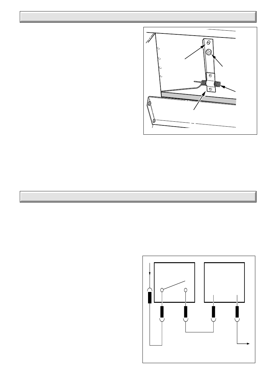
9.10 Flue Blockage Safety Device
Gain access as Section 8.1.
Remove the electrical connections, see diagram 9.6
Remove capillary from cable clips, see diagram 9.7.
To remove the phial assembly, first gain access through flue
cleaning door as Section 8.1.
Unscrew securing nut and withdraw the phial assembly from the
location stud, see diagram 9.8.
Remove the safety device securing locknut complete with phial
assembly, see diagram 9.6.
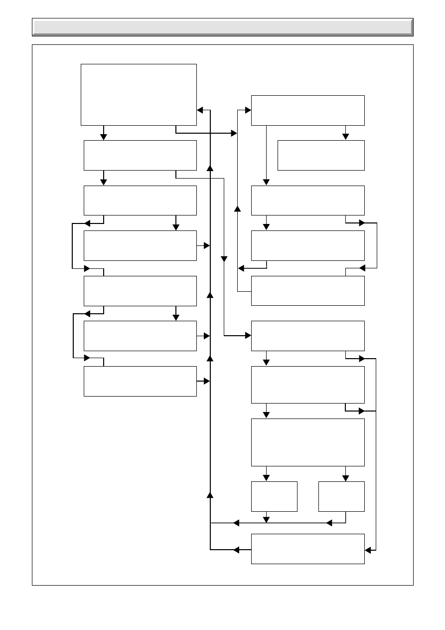
10.1 Electrical
Refer to functional flow diagram 10.1, electrical fault finding
chart, diagram 10.2 and wiring diagram 9.2.
IMPORTANT. The preliminary electrical system checks
contained in a multimeter instruction book are the first checks
to be carried out during and fault finding procedure. On
completion of the service fault finding task which has required
the breaking and remaking of electrical connections then checks.
earth continuity, polarity and resistance to earth must be
repeated.
10.2 Thermocouple
To test the thermocouple a meter with a range 0 to 30mV is
required together with a thermocouple interrupter test unit
similar to the British Gas Multimeter and interrupter.
Refer to thermocouple fault finding chart, diagram 10.3 and
diagnosis graph, diagram 10.4.
10.3 Pilot and Ignition
Refer to pilot and ignition fault finding chart, see diagram 10.6
and 10.3.
10.4 Flue Blockage Safety Device
If the device operates it indicates there is a problem with the
chimney. Make sure that the air vents are free from obstruction.
Carry out spillage checks as BS5440 Part 1 and put right as
necessary.
FUNCTIONAL FLOW WIRING
Diagram 10.1
0900
C
N/C
L
N
RED
BLUE
ORANGE
3
4
GAS VALVE
CONTROL
SOLENOID
THERMOSTAT
10 Fault Finding - Electrical
21
221808B
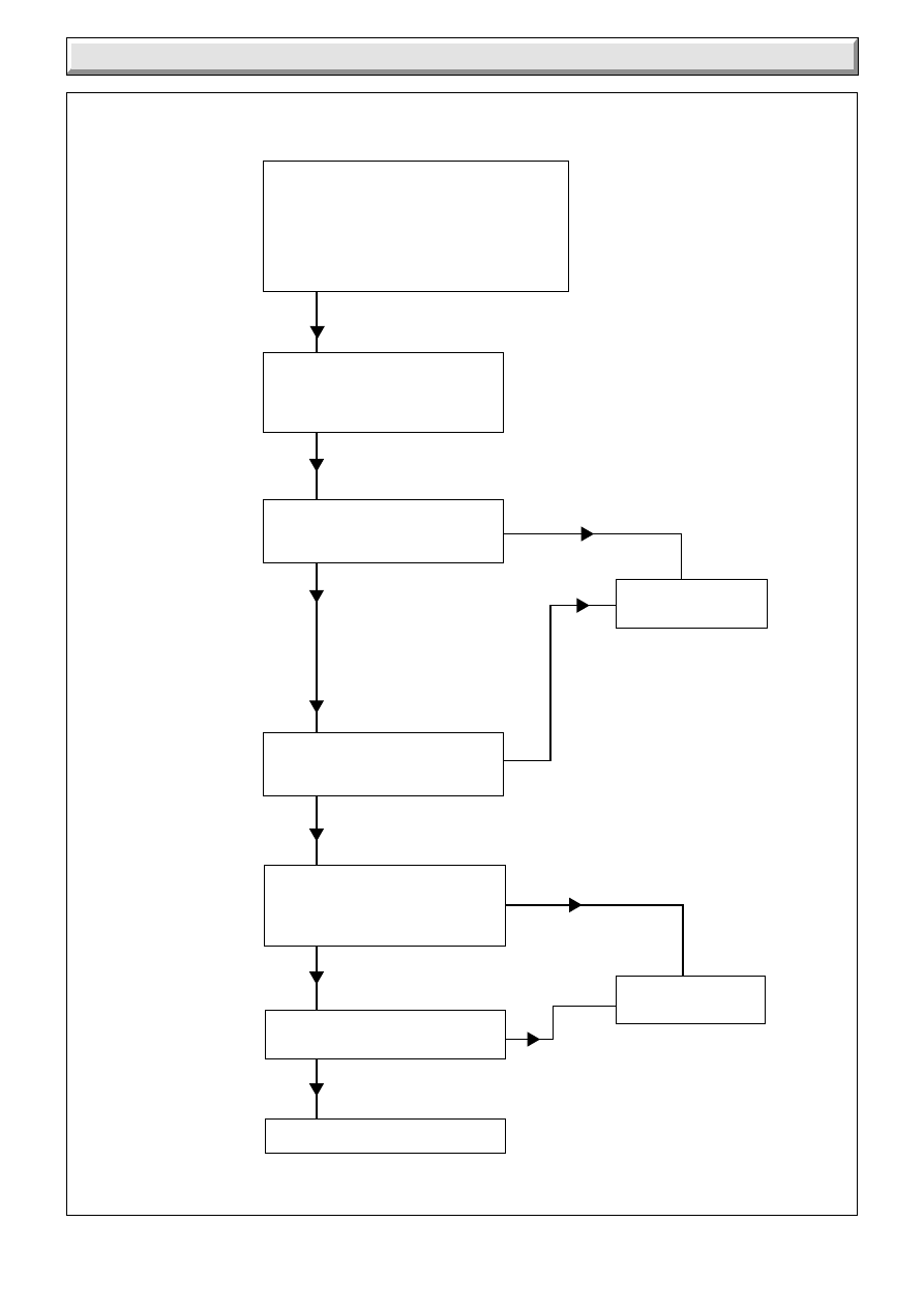
10 Fault Finding - Electrical
Diagram 10.2
ELECTRICAL FAULT FINDING
Faulty gas valve.
Replace.
Turn boiler thermostat to "O'.
Does main burner extinguish.
Boiler controls in order.
Carry out preliminary electrical checks to
make sure the electrical supply is available
at the boiler. Check that external controls
are calling for heat. Make sure that the
system is filled, the flue blockage safety
device is reset, the gas supply is available
and the pilot is lit.
Isolate electrical supply to the
control box.
Remove the control box cover and
check all cables.
Turn boiler thermostat to Max.
Is there continuity between
'C' and 'NC'.
Turn boiler thermostat to 'O'.
Is there open circuit between 'C'
and 'NC'.
Faulty thermostat.
Replace.
Restore electrical supply with pilot
burner lit and boiler thermostat set
between 'MIN' and 'MAX', does the
main burner light.
NO
NO
YES
NO
YES
NO
YES
YES
0899/A
22
221808B
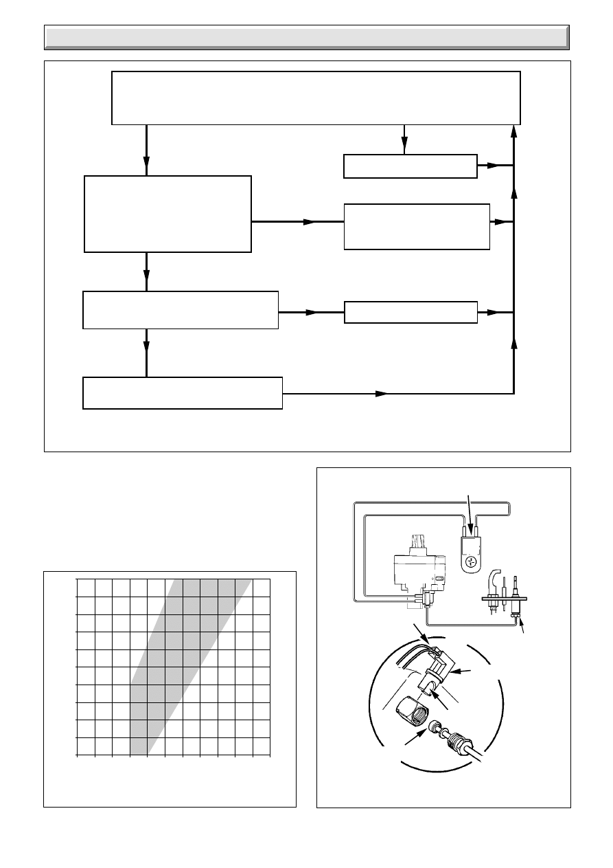
Re-connect boiler flue blockage
safety device to points A and B.
Disconnect thermocouple at
connection point D of the gas valve.
Test continuity between point C and the
body of the gas valve.
Is there continuity?
Test continuity of thermocouple between inner
connection point D and point E.
Is there continuity?
Faulty boiler flue blockage
safety device, renew.
Thermocouple and boiler flue blockage
safety device circuit satisfactory.
NO
YES
YES
Faulty flue blockage safety device
connectors into gas valve,
either at A or C.
Renew where faulty.
Faulty thermocouple, renew.
With the boiler cold, check connections of the thermocouple, boiler flue blockage safety device
and gas valve. Reset flue blockage safety device.
Disconnect flue blockage safety device connectors at points A and B at the gas valve,
see diagram Interrupter Electrical Connections.
Test continuity of the flue blockage safety device. Is there continuity?
YES
NO
NO
10 Fault Finding - Thermocouple
2327/B
Diagram 10.3
THERMOCOUPLE AND FLUE BLOCKAGE SAFETY DEVICE
FAULT FINDING
FLUE BLOCKAGE SAFETY DEVICE
CONNECTION "D"
POINT "C"
GAS VALVE
5031
INTERRUPTER ELECTRICAL
CONNECTIONS
Diagram 10.5
CONNECTION "A"
CONNECTION "B"
CONNECTION "E"
Closed Circuit Voltage (millivolts)
Open Circuit Voltage (millivolts)
0
2
4
6
8
10 12 14 16 18 20 22
9
11
13
15
17
19
21
23
25
27
29
A
B
C
Diagram 10.4
DIAGNOSIS GRAPH FOR
THERMOCOUPLE CIRCUIT
1546
23
221808B
10 Fault Finding - Pilot
Diagram 10.6
PILOT / IGNITION FAULT FINDING
0905A
START HERE
Check gas line - open all cocks,
rectify any blockages, purge out
any air. Check flue blockage
safety device is reset,
check all thermocouple circuit
connections are clean and in good
condition. Does pilot light?
Does pilot stay alight when
gas valve knob is released?
Check aeration. If necessary -
Clean pilot, rectify blockage in
pilot injector, or replace.
Check thermocouple circuit using
Thermocouple Fault - Finding
diagram.
On pressing piezo unit button
is there a spark across
electrode gap?
Pull ignition lead off electrode.
Hold end of lead close to pilot
burner and operate piezo unit.
Is there a spark across gap?
Check electrode gap. Reposition,
or replace electrode as necessary.
Change
piezo unit.
Change
ignition unit.
Pull ignition lead off piezo unit.
Using blade of a screwdriver,
touch unit chassis and leave
approx. 4mm gap from connection
tag on piezo unit. Operate piezo.
Is there a spark across gap?
Does pilot flame
envelope thermocouple?
Apply match to pilot burner instead
of pressing piezo unit button.
Does pilot light?
Undo tubing nut at pilot burner.
Press gas valve knob.
Does gas flow freely?
Undo tubing nut at pilot outlet of
gas valve. Press gas valve knob.
Does gas flow freely?
Rectify blockage in pilot injector,
or renew pilot injector.
Change blocked pilot tube.
Change gas valve.
PILOT SATISFACTORY
NO
YES
NO
YES
NO
YES
NO
YES
NO
YES
NO
YES
NO
YES
NO
YES
NO
YES
24
221808B
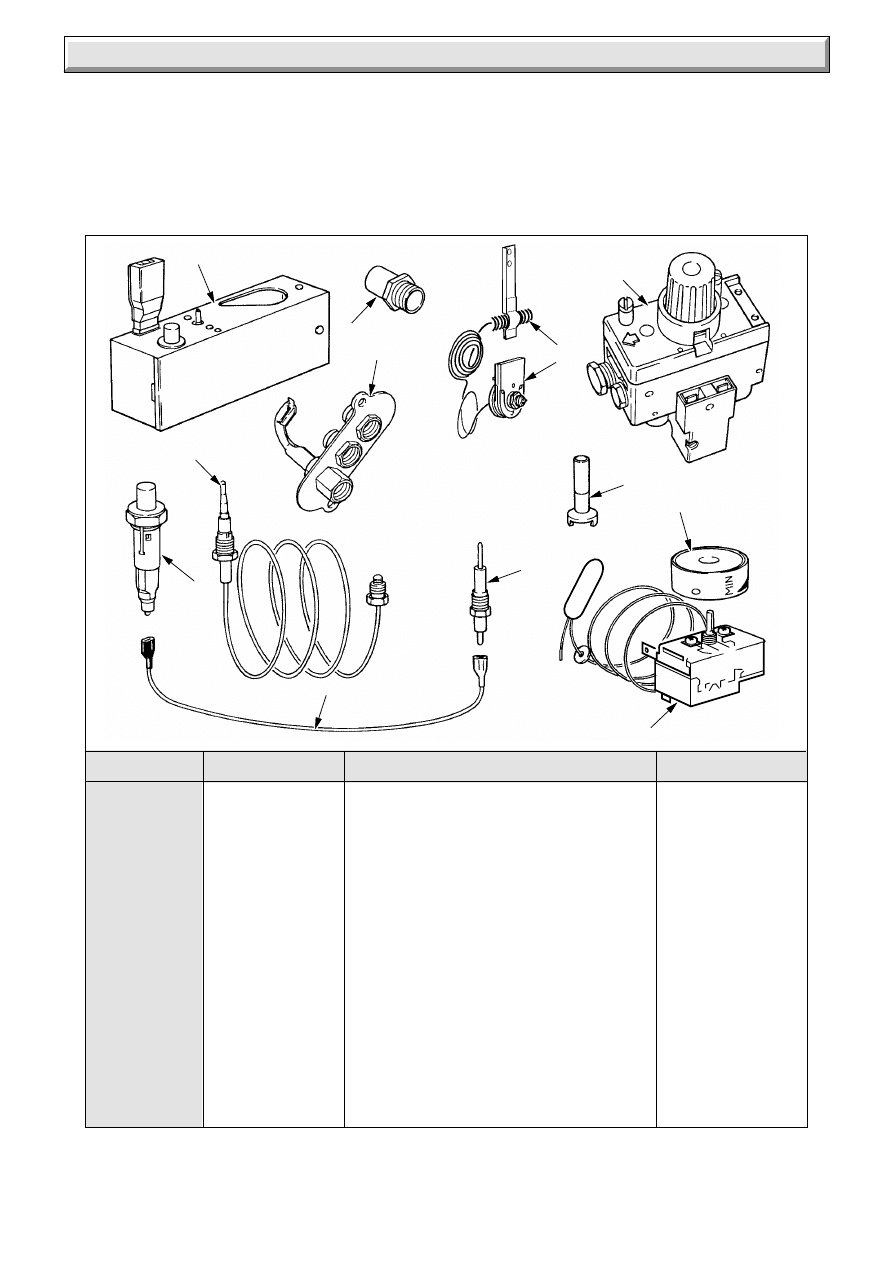
11 Spare Parts
1
425568
Electrical control box assy
312 451
2
203329
Gas control valve
384 345
3
205752
Injector - 50
4
203414
Pilot burner assy
312 246
5
203508
Injector - pilot
395 674
6
900001
Thermocouple c/w nut
7
202571
Thermostat c/w screws
8
FF2228
Control knob assy
355 241
9
900501
Piezo unit
382 585
10
WW4613
Ignition lead
136 399
11
202605
Spark Electrode
395 720
12
425794
Flue Blockage Safety device
E02686
Key No
Part No
Description
GC Part No
6125
1
2
8
5
7
11
10
9
3
12
6
4
11.1 Part Identification
The key number in the first column of the list will help identify
each part shown in diagram 11.1.
11.2 Ordering
When ordering spare parts quote the part number and
description, stating the model and serial number off the data
label “L”, see diagram 7.1.
If ordering from British Gas also quote the GC appliance
number off the data label and the required spare part GC
number.
Diagram 11.1
Because of our constant endeavour for improvement, details may vary slightly from those shown in these instructions.
Wyszukiwarka
Podobne podstrony:
Glow Worm installation and service manual Hideaway 50CF
Glow Worm installation and service manual Hideaway 70CF UIS
Glow Worm installation and service manual Ultimate 50CF UIS
Glow Worm installation and service manual Hideaway 80BF UIS
Glow Worm installation and service manual Hideaway 120BF UIS
Glow Worm installation and service manual Hideaway 120CF UIS
Glow Worm installation and service manual Hideaway 100CF UIS
Glow Worm installation and service manual Hideaway 70BF UIS
Glow Worm installation and service manual Hideaway 80CF UIS
Glow Worm installation and service manual Hideaway 40BF UIS
Glow Worm installation and service manual Hideaway 50BF UIS
Glow Worm installation and service manual Hideaway 60CF UIS
Glow Worm installation and service manual Hideaway 40CF
Glow Worm installation and service manual Hideaway 70CF UIS
Glow Worm installation and service manual Ultimate 50CF UIS
Glow Worm installation and service manual Hideaway 100CF UIS
Glow Worm installation and service manual Hideaway 120BF UIS
Glow Worm installation and service manual Hideaway 120CF UIS
więcej podobnych podstron