A Flywheel Switched Reluctance Motor Drive for Wind Energy Applications
I.J. Iglesias
1
, L.García-Tabarés
1
, M.Lafoz
1
, J.Calero
1
, S.Portillo
1
, I.Cruz
2
, F.Toral
2
, P.Abramian
2
1
Centro de Estudios y Experimentación de Obras Públicas (CEDEX)
Centro de Estudios de Técnicas Aplicadas
AlfonsoXII, 3. 28014 Madrid
phone:+ 34913357320 –fax:+34913357257-e-mail:Jorge.Iglesias@cedex.es
2
Centro de Investigaciones Energéticas MedioAmbientales y Tecnológicas (CIEMAT)
Av Complutense, 22,28040, Madrid
Abstract- This paper describes the design and fabrication of a
switched reluctance Machine (SRM) drive for a flywheel as
part of a wind/diesel stand-alone generator, in order to
minimise the number of start-stop cycles of the diesel engine.
After an explanation of the complete system, the paper
analyses the design and manufacturing of the SRM, followed
by a description of the bi-directional power converter.
1. Introduction
Even nowadays, we tend to forget that there are still
many locations in the world, which do not have an
electrical connection to a central network. Furthermore, in
many remote places, it is unlikely that the connection to
the main grid will never be established. However, the need
for power still exists. At present, the most common way to
supply electricity to remote loads, is with a diesel engine
driving a generator set, but many of those places are in
regions of high wind potential.
In this sense, in 1998 we started the SEDUCTOR
project as part of the Spanish Plan of Electrotechnical
Research. The aim of this project has been to develop an
innovative wind/diesel system [1], including a low price,
high-speed flywheel as short -term energy storage system.
The system is intended for the market of stand-alone
power supply units of 50 kW or more. Four partners co-
operated in the project: CIEMAT, CEDEX, UPM and IIT
on the design and development tasks and several
companies have collaborated in the project at different
levels like: ENERTRON, GRUMADISA, BORNAY
AEROGENERADORES.
Due to the fact that wind power is proportional to the
cube of the speed, the presence of short term wind speed
fluctuations (turbulences in order of seconds to minutes),
and the variability of the electrical load would involve
continuous operation of the diesel with a high fuel
consumption (below 40 per cent of rated power,
consumption can be significant and wasteful).
In order to minimise the frequent start-stop cycles which
would be associated with turning the diesel on and off, it is
convenient to use some kind of short-term energy storage.
There exist several candidates for short-term energy
storage: batteries, flywheels, hydraulic accumulators or
supercapacitors. Flywheels are particularly well suited to
this application because they offer a fairly high energy
density and long lifetime, even under the fast
charge/discharge conditions, which are typical of wind-
diesel applications.
2. System Description
The system works in the following way [2]: when the wind
power exceeds the load by some specified amount, the
diesel generator is disconnected by an electromagnetic
clutch from the engine, which is stopped. The synchronous
generator continues to spin supplying the necessary
reactive power to the network, as the induction generator
of the wind turbine is unable to supply it. At this moment,
the flywheel driven by a high-speed switched reluctance
motor (operating asynchronously through a frequency
converter), follows the power variations, accelerating when
the energy is absorbed and decelerating when the energy is
released to the system. By allowing large speed variations
(from 5,000 rpm to 30,000 rpm) the amount of energy
which can be handled with a 50 kW flywheel, can be
considerably increased.
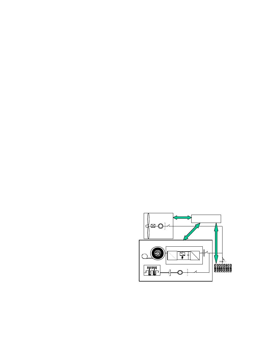
This 50 kW peak power, 1.25 kWh stored energy,
flywheel system consists of a bi-directional power
converter, a high-speed Switched Reluctance Motor
(SRM), a hybrid composites made rotor and a container.
All the main components of the full facility are depicted in
figure 1.
Fig. 1. Main components of the facility
The bi-directional power converter is based on IGBT
technology. It consists of a line-side full bridge three-phase
PWM Converter, a SRM High Frequency Driver and a
DC/DC Chopper connected to the 750 V DC-link in order
to dissipate the surplus wind energy in resistances, if the
flywheel speed reaches the upper allowable limit.
DIESEL ENGINE 62 C.V.
WIND TURBINE
ASYNCHRONOUS
GENERATOR
50 KW 400 V
GEARBOX
.
PROGRAMMABLE LOADS
100 KW
MULTICONVERTERS
& PROTECTIONS
ELECTROMAGNETIC
CLUTCH
50 KW SYNCHRONOUS
GENERATOR
VACUUM
PUMP
50
kW
SWITCHED
RELUCTANCE
MOTOR (SRM)
FLYWHEEL RIM
ROTOR
CONTAINEMENT
AC
DC
DC
AC
DC
DC
50
kW
B I-DIRECTIONAL POWER CONVERTER
VSI CONVERTER
CHOPPER
DISSIPATION LOADS
AS DUMP LOADS
SG
AG
MODULAR SUPERVISORY,
CONTROL AND DATA
ACQUISITION SYSTEM
CONTAINER
MOTOR DRIVE
STALL
REGULATED
The 50 kW high-speed electrical machine is a three-
phase, 6/2 poles SRM very robust and simple. It uses
commercial hybrid bearings (ceramic balls/steel rings)
which are stiff, reliable and low costs devices.
The energy storage rotor is based on concentric thick
rings, wound over an inner steel ring, with an overall mass
of around 70 kg. The set motor-rotor is enclosed in an
evacuated container to reduce aerodynamic losses and to
prevent accidents in the event of a rotor bursting. The
rotor weight can be reduced drastically, because it can
withstand very high rotational speeds and the strength of
its protective container can be minimised due to the very
advantageous destruction mechanism. (no heavy parts can
break apart from the rotor).
One additional advantage of this flywheel system is that
the storage unit can be located far from the rest of the
system, inside a commercial container for instance,
allowing to have a portable system.
3. The Flywheel Driving Machine
To accelerate and to brake the flywheel, an electrical
machine is needed, acting as a motor in the first case and
as a generator in the second one. There are a few types of
machines candidates for this purpose and after an specific
analysis for our application we concluded that the best
choice was to use a Switched Reluctance Machine (SRM),
according to the following criteria:
- Low price and maintenance
- Low losses in the rotor and high overall efficiency
- Good capability for working at high speed
This section describes the design and fabrication of the
SRM as well as some individual tests which were
performed to validate this design.
3.1. SRM Design
Before describing specific aspects , some general remarks
regarding the overall design and manufacturing should be
done. As it is well known the SRM allows a relatively
wide number of configurations concerning the number of
poles and phases [3]. The final choice is basically a trade-
off between torque ripple and maximum electrical
frequency at the driver output. In order to achieve low
ripple and to reduce the frequency to admissible values for
the maximum rotational speed (30,000 rpm), the number of
stator phases was set to 3, while the number of rotor poles
was chosen to be 2, thus leading to 6 stator poles.
From the manufacturing point of view, the design was
focussed on realising a compact and robust machine and
this is basically achieved by using curved coils which fit
very well to the stator geometry, allowing a good thermal
contact and reducing the ext ernal diameter of the machine.
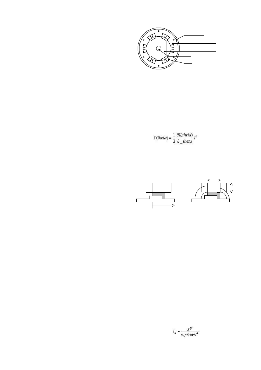
Figure 2 shows a cross section of the SRM indicating its
main components.
Most of the main aspects of the design were based on the
previous experience developed in a 2kW prototype which
was built before according to the same basic principles [2].
Fig. 2.- Cross section of the SRM
3.1.1. Magnetic Design
Magnetic design basically aims to define, from some initial
constraints, the size and geometry of the machine to
achieve the required values of torque at a given speed.
If the machine is considered as a linear magnetic system,
the torque for a constant current I can be derived from the
self-inductance variation of the actives poles, L(theta),
with the rotor position, theta, as:
(1)
A first and simple model to evaluate L(theta) (model a)
can be deduced with the help of figure 3.a, where only the
central flux between the rotor and the stator is considered.
a) b)
Fig. 3.Flux model. a) Only central flux b) Lateral flux included
Simple application of Ampere´s law, allows to find an
expression for the flux density in the air gap and hence,
for the self-inductance L(theta), as a function of the
minimum air gap g, the air gap radius R, the number of
turns per pole N, the number of pole pairs per phase p and
the stator depth, d:
=
?
?
(2)
=
?
?
The SRM converter will normally operate the machine
at the required current value. This model, nevertheless,
establishes a limit, I
m
, to the current, imposed by the d.c.
voltage
V and the rotational frequency
w as
V·theta/wL(theta). From (2), it yields:
(3)
Shrink fit tube
Stator iron laminations
Rotor iron laminations
Shaft
Coils
g
theta
STATOR
STATOR
ROTOR
ROTOR
w
h
3
2
3
for
)
3
/
2
(
)
(
3
0
for
)
(
2
0
2
0
pi
theta
pi
theta
pi
g
pRdN
u
theta
L
pi
theta
theta
g
pRdN
u
theta
L
-
Equations (1) and (2) provide an expression for the
developed torque corresponding to this simple model as:
(4)
The complete determination of the torque during the
active period of each phase, has to consider the overall
evolution of the current, including the switch-on and the
switch-off intervals.
A more precise self-inductance and thus torque
determination can be done if lateral flux through the poles
is also taken into account as it is depicted in figure 3.b,
(model b) ,where the lateral field lines are approximated by
circular wedges [4]. It can be shown that for this model,
the torque for motoring operation is given as:
(5)
Symmetrical expressions with respect to pi/3 are
obtained for generating operation. Equations (2) through
(5) allow a first evaluation of the machine dimensions if
some further constraints are made as the allowable stresses
in the rotor, the maximum flux density in the iron or the
conductor size.
Although the previous models provide a good approach,
a more precise analysis using a F.E.M. method is
mandatory for an accurate computation of L(theta), which
also allows to define the optimum switch-on and switch-
off strategy to achieve the best torque shape for every
condition.
Figure 4 shows the F.E.M. calculated values of L(theta)
(-pi/6 to pi/3 interval and no saturation) for the designed
SRM, compared to those provided by models a) and b).
Fig 4. F.E.M and Analytical computation of L(
?
)
Precise calculation of the torque also need for F.E.M.
simulation as saturation becomes important at high current
levels and the torque can not be derived from simple
expressions as (1). Later on, some results will be
discussed and compared to experimental static torque
measurements.
Table 1 shows a list of the main parameters of the
machine. Some of them can be considered as input
variables, while the rest are derived from the above
described magnetic design.
TABLE I
Main Parameters of the SRMachine
PARAMETER
VALUE
Rotor outer radius
71 mm
Stator outer radius
117 mm
Air gap
2/4 mm
Active length
110 mm
Nº of turns per pole
18 (9+9)
d.c. Voltage
750 V
RMS current per phase at max. torque
70 A
Maximum torque
16 Nm
Maximum speed
30,000 rpm
Maximum power
50 kW
3.1.2. Thermal Design
Thermal design is specially relevant for this application as
the machine will operate under vacuum conditions and
heat evacuation can only be done by conduction to the
outer wall of the stator, where a fan will remove the
conducted heat. There are, basically two sources of heat:
Joule losses in the coils and iron losses in both rotor and
stator laminations. From the current and the coil resistance,
evaluation of the first term is straight forward, while
determination of the second one is more complicated and it
has been done on the basis that every time one phase is
magnetised and demagnetised, one-quarter of the
hysteresis loop is described. From the data sheet of the
magnetic material, hysteresis iron losses per kg have been
expressed as a function of the electrical frequency which
corresponds to six times the rotational frequency. For our
design, iron losses in the stator at maximum r.p.m. and
current can rise up to 215 W.
A simplified model based on the classical conduction
equations has been developed. Figure 5 shows the
corresponding geometry as well as the electrical equivalent
circuit for the thermal analysis.
Fig.5. Thermal model for temperature computation
In the equivalent electrical circuit, heat sources are
replaced by current sources, and thermal resistances by
electrical resistances whose values are calculated from the
thermal conductivity and dimensions of the represented
element. The goal of the model is to evaluate the maximum
temperature, which is achieved at the inner side of the coil
0
0 .000 5
0 .001 0
0 .001 5
0 .002 0
-4 0
-2 0
0
2 0
40
60
A naly tic al ( M odel b)
A naly tic al (Model a)
F. E. M
?
(DEGREES)
L
(
?
)
H
STATOR (Iron losses)
COILS (Joule Losses)
Insulation
Qj=Joule losses
Qh=Iron losses
Ri=Insulation thermal resistance
Rs= Stator thermal resistance
3
2
3
for
2
3
0
for
2
2
2
0
2
2
0
pi
theta
pi
I
g
pRdN
u
T
pi
theta
I
g
pRdN
u
T
a
=
?
?
= -
?
?
and can be calculated as the voltage at the node pointed
with an arrow in figure 5.
The most uncertain parameter for the simulation is R
i
, as
the contact surface of the insulated coil and the stator is far
from being 100% of the maximum value. From
experimental observation during fabrication of the SRM,
R
i
has been chosen as twice the theoretical value for full
contact. Simulations for the worst conditions( maximum
current and speed) predict a peak temperature of 35ºC over
the stator outer wall. Some experimental thermal
measurements will also be discussed later on.
3.2 Machine Fabrication
The most peculiar component of our SRM are the curved
coils which were wound in a “double pancake”
configuration using a special winding machine able to
wind two layer curved coils in one step. The coils are
impregnated afterwards in a mould, to achieve precise
dimensions and mechanical stability.
Iron laminations for both, rotor and stator were cut using
an spark-erosion machine as a classical punching
procedure became too expensive for a prototype. The rotor
laminations were guided into position through the shaft,
while stator ones were placed into position by means of
non-magnetic rods. Once the stator was mounted, the
shrink fit external cylinder (galvanically insulated) was
placed into position to hold the full assembly. The coils
were insulated from the back iron with a relatively high
thermal conductivity tape and once they were placed into
position, the rotor was inserted and the two end plates with
the hybrid bearings (ceramic and steel) were mounted.
External connections are placed radially to achieve a more
compact design and pole interconnections were made by
means of copper rings. The machine includes o-rings at
both ends to guarantee vacuum tightness.
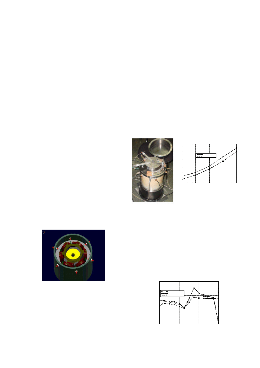
Figure 6 shows a 3-D view of the machine where the
coils, the external and internal connections, the rotor and
the stator can be seen.
Fig.6. 3-Dimensional view of the SRM
To monitor the rotor position for switching the
converter, a grooved disk was fixed at one end of the shaft.
A set of photo-diodes and photo-transistors placed in
between the disk, were in charge of coding the rotor
position. Temperature sensors were also placed at the inner
side of the coils ends as well as closed to the bearings to
monitor this magnitude during machine operation.
3.3. Machine Tests
After the machine was built, some initial tests were
performed to verify general aspects of the operation.
During this stage, the speed was limited to 12,000 rpm and
magnitudes such as temperature in the bearings or phase
current shapes were recorded. Rotor position signals were
also adjusted to optimum levels.
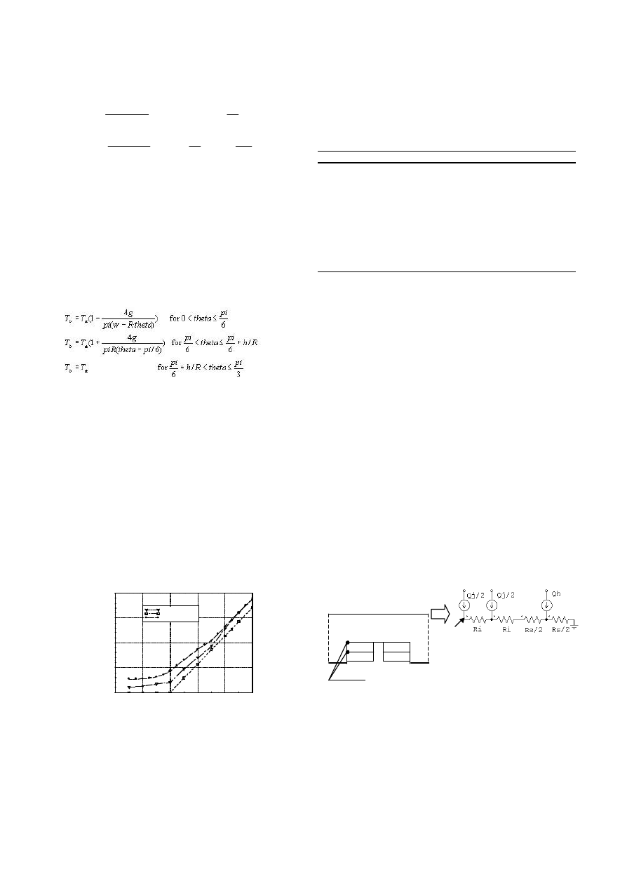
Two more specific tests were then performed, closely
related with the SRM design aspects. The first one was
strictly thermal. A d.c. current was applied to the coils and
the temperature increasing recorded and compared to
theoretical predictions. During this test, the machine was at
stand still so that only Joule losses were generated. Tests
were performed at different current levels as it is shown in
figure 7.b, which is a plot of incremental temperature (coil
minus external wall) versus current. Theoretical
predictions are also compared in the same plot.
As it can be seen, these predictions show that thermal
insulation resistance has been underestimated in a factor of
about 10% .
Fig. 7. a) Set up for torque measurements b) Thermal measurements
The second test was the measurement of static torque. A
certain phase of the machine is energised at stand-still and
the force exerted against a plate with a strain-gauge sensor
measured for different rotor positions. Figure 7.a shows a
picture of the SRM with the torque measuring device at the
top, while figure 8 is a comparison of measured and
calculated static torque values using F.E.M. and
expressions from model b) for a d.c current of 30A. In the
short term it is foreseen to measure at higher currents
where saturation can have a significant role. As much
higher torques will be developed, the force sensor must be
adapted.
Fig .8. Static torque results for 30 A.
0
10
20
30
20
30
4 0
5 0
60
PR EDI CTED
EXP ERI MENTA L
I (A)
?
T
(º
C
)
a) b)
0
0.4
0.8
1.2
0
2 0
4 0
60
A nalyt ical (Model b)
F EM Cal culat ions
E xperiment al
?
(DEGREES)
T
O
R
Q
U
E
(
N
m
)
4. Switched Reluctance Motor Drive
A double bi-directional power converter will drive the
switched reluctance motor. This converter is composed of
a AC/DC converter, an asymmetrical half-bridge converter
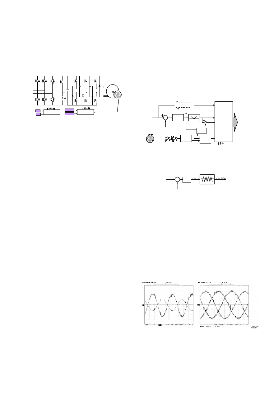
and a DC chopper. Figure 9 presents the topology of the
two converters and the DC chopper [5].
Fig. 9. Double converter and DC chopper topology.
The network side converter is a conventional hysteresis -
band current controlled VSI, capable of injecting or
absorbing both active and reactive power into the network,
according to some external control references. Based on d-
q transformation of the network voltages, a voltage phase
detector has been developed in order to shift the current
waveform with an appropriate delay according to the
reactive power reference.
The motor side converter presents a half-bridge topology
with two IGBTs and two diodes per phase, this topology
allows the SRM to operate as a motor or generator,
depending on the system requirements, with an almost
complete symmetry between these two operation modes.
Figure 10 presents the SRM converter control block
scheme [2],[3]. The DC voltage will be modify by the
network according to the amount of the injected or
absorbed power. The SRM converter is controlled with the
objective of maintaining the DC voltage close to a fixed
reference value. This is achieved with an absolute value
limited PI controller.
In this way, a decrease of this voltage in the motor
operation mode will cause a decrease of the current
amplitude reference. However a decrease of DC voltage, in
the generator operation mode, will cause an increase of the
current amplitude reference.
When the current reaches the maximum limit (PI
controller saturated) the DC voltage is moving away from
the nominal value. If it is outside the voltage hysteresis
band defined around the nominal value, the operation
mode should be changed. For example, if the SRM is
working as a generator and the DC voltage increases over
the upper voltage limit, it will change to the motor
operation mode. In this situation, the SRM evolves from
supplying to receiving power from the DC link. Therefore,
the DC voltage decreases while the rotational speed
increases.
A speed control is also implemented in order to ensure
the mechanical safety of the system. If the rotational speed
overpasses a defined maximum speed, the generation
operation mode is the only one permitted. In the same way,
if the rotational speed is lower than a defined minimum
speed, the motor operation mode is the only one permitted,
not depending on the voltage control both cases. This
algorithm acts therefore as an electrical brake.
If the wind generator supplies an excessive power, the
grid frequency will be increased. The control reacts
increasing the absorbed power towards the storage system.
If the SRM reaches the maximum speed in the motor
operation mode, no more energy can be stored. Therefore,
the DC voltage increases. As the double converter is not
able to avoid it, a DC chopper is used to dissipate the
excessive power into an electrical resistor, maintaining the
DC voltage level. The DC chopper has an analogue
control presented in figure 11.
Fig. 10. SRM converter control block scheme.
Fig. 11. DC chopper control block scheme.
Both network converter and SRM converter control is
based on a Digital Signal Processor (Lucent DSP32C) and
a microcontroller (Hitachi H8) for the algorithms
calculation. Analogue current comparators are used to
generate the IGBT switching pulses.
5. Experimental Results
A 50kW bi-directional power converter and a DC
chopper are constructed to drive the SRM. Some
experimental results obtained with the complete three
electronic converters, working together, are presented in
this chapter in order to check the good behaviour of them.
(a) (b)
Fig. 12. Network-side converter phase voltage and current.
Figure 12(a) shows the network voltage together with
the line nominal current (75A) when the network-side
converter supplies energy to the network. No reactive
P.I.
Vdc_max
Vdc_min
Operation Mode
(Generator - Motor)
Current
limits
Band Width
I
lim
M o t o r
Generator
I
max
I
min
DC Voltage
Reference
DC Voltage
Measurement
S1 -> (BIT bajo)
S3 -> (BIT medio)
S2 -> (BIT alto)
Rotational
speed (w)
Rotor
Angle (? )
DSP Sextant
Detection
On and off
angles
calculation
IGBTs
switching
pulses
generation
Current
Measurement
(Ir, Is, It)
- Phases
activation.
- Current
comparation.
- Hard/Soft
switching.
12 IGBTs
switching
pulses.
Speed
Protection
Optical
Sensor
Sextant
Phase A
Phase B
Phase C
Phase B
Phase C
C
SRM Inverter
Front-End Inverter
Control Unit
P
ref
Q
ref
SRM Inverter
Control Unit
V
dc (measured)
V
dc (reference)
Phase A
SRM
R
S
T
VSI
Chopper
Discharge
Resistors
P.I.
Chopper IGBT
switching pulses
DC Voltage
Measurement
Chopper
DC Voltage
Reference
power is supply in this case. Also, three phases line current
are shown in this figure (b).
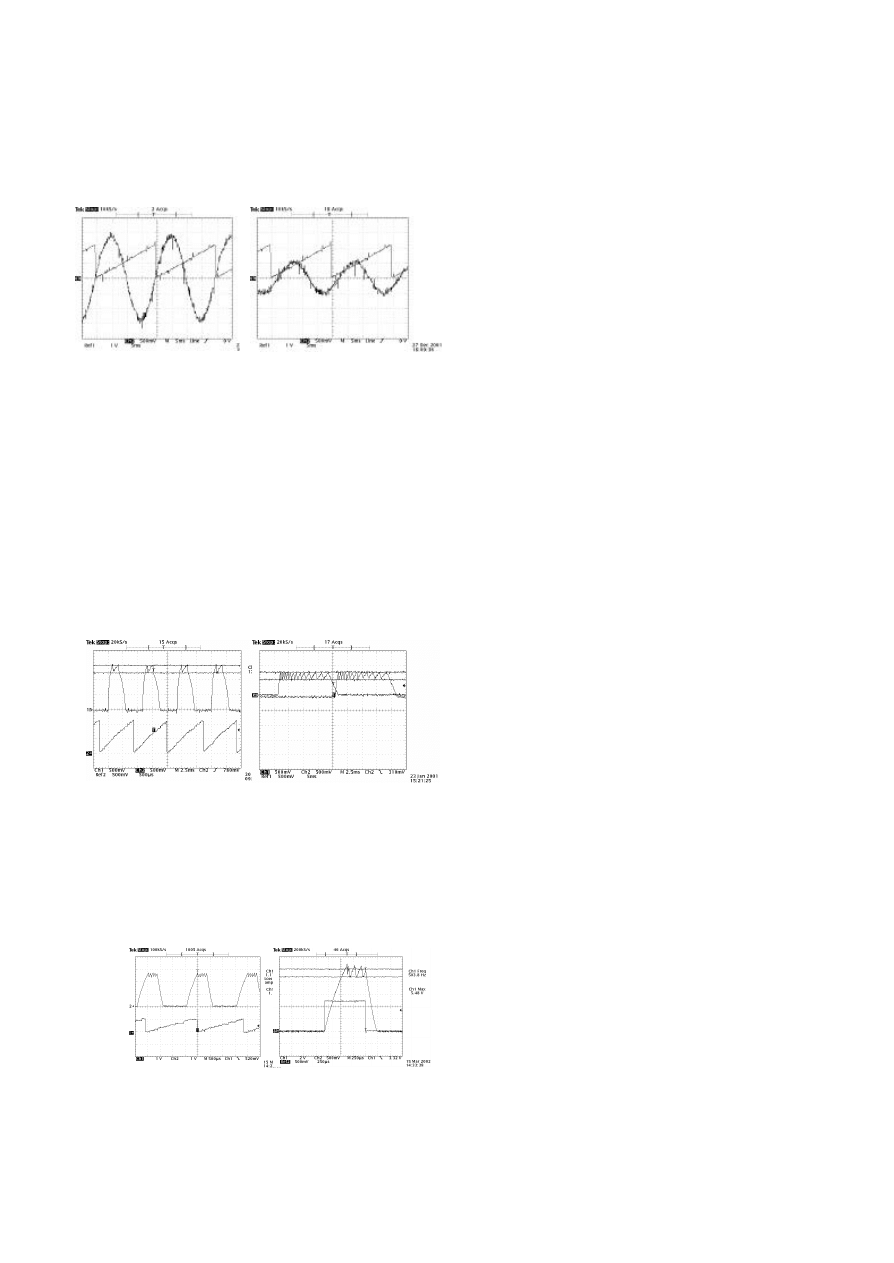
Figure 13 presents the estimated network voltage phase
and the current waveform based on it when reactive power
reference is zero and when some reactive power reference
is given to the control system.
(a) (b)
Fig. 13. Line current and estimated voltage phase.
Three optical sensors and a grooved disk are used to
determinate the machine rotor angle in the DSP. Figure
14(a) shows the rotor angle estimation by the SRM
converter control and one phase current waveform,
activated in the appropriate angle interval in order to get
the maximum torque. In this way, a simulation study with
SABER has been developed for different speed situations,
getting the most appropriate on and off angles for the
IGBT switching in order to obtain the maximum torque.
Current commutation limits are also presented in figure
14(b). The lower current limit can be changed and
determinates the IGBT conmutation frequency.
(a) (b)
Fig.14. SRM current, rotor angle detection and current
commutation limits.
Figure 15(a) shows one phase current waveform and the
estimated rotor angle and figure 15(b) a detail of the
current commutation limits and current activation signal,
when 160A are obtained from the SRM converter with a
15000 rpm speed.
(a) (b)
Fig. 15.SRM converter current results.
6. Conclusions
We have presented the description of a switched
reluctance drive for applications as an energy storage
system for a stand alone wind generator acting as an output
power filter.
-
The SRM is a 6/2 pole unit which has been selected
for its robustness, efficiency and capability of
working at high speeds. A conceptual and basic
design based on simple magnetic considerations has
been the core of the overall design which was refined
using F.E.M. computations. Special importance was
given to the thermal calculations as the device runs
under vacuum conditions.
-
This machine has been built using a “double pancake”
procedure for winding the coils which fit to the stator
back iron allowing a good thermal evacuation to the
outside. Experiments have been performed to confirm
both, the electromechanical and the thermal
behaviour.
-
A bi-directional converter is used to drive the SRM
and injecting or absorbing the required active and
reactive power from an external frequency and
voltage control. In the SRM converter, a current
control, an operation mode selection, a speed control
and a DC chopper will maintain the DC voltage in the
reference value.
-
Experimental results demonstrate the good behaviour
of the double converter and the DC chopper, in the
nominal current situation.
7. References
1. Ray Hunter & George Elliot (1994) “Wind Diesel Systems. A
Guide to the Technology and its Implementation”. Edited by
Cambridge University Press.
2. Iglesias I.J. L García-Tabarés ,A. Agudo, I. Cruz and L.
Arribas ”Design and Simulation of a Stand-alone Wind-Diesel
Generator with a Flywheel Energy Storage System to Supply
the Required Active and Reactive Power”. I.J. Proceedings of
the31
st
Annual Power Electronics Specialists Conference. Vol.
3. pp 1381-1386.
3. Miller, T.J.E. “Switched Reluctance Motors and their control”.
Magna Physics Publishing & Clarendon Presss. Oxford.1993.
4. J. Kokernak, D.Torrey.” Magnetic Circuit Model for the
Mutually Coupled Switched Reluctance Machine”. IEEE
Transactions on Magnetics. Vol. 36 nº2 March 2000.
5. S.Mir “ Classification of SRM Converter Topologies for
Automotive Applications”. SAE 2000 World Congress.
Detroit, March 2000.
Wyszukiwarka
Podobne podstrony:
[2000] Long term R&D Needs for Wind Energy
Directly Driven Low speed Permanent Magnet Generators For Wind Power Application
A neural network based space vector PWM controller for a three level voltage fed inverter induction
A Low Speed, High Torque, Direct Drive Permanent Magnet Generator For Wind Turbines
(Wind) A Low Speed, High Torque, Direct Drive Permanent Magnet Generator For Wind Turbines
Plans For Wind Generator Pt250 Blade Plan10A
Blade sections for wind turbine and tidal current turbine applications—current status and future cha
Compliant Blades For Wind Turbines
Time Series Models For Reliability Evaluation Of Power Systems Including Wind Energy
Bearden Tech papers Vision 2000 The New Science Now Emerging for the New Millennium (www cheniere
Small Wind Energy Systems for the Homeowner
Ebook Wind Power Savonius Generator Wind Energy For Earth Keepers Savonius Wind Mill
Vector Controlled Doubly Fed Induction Generator for Wind Applications
Wind Turbine 5 Metre Diameter Carbon Fibre Blades For Wind Turbine10Kwblades
Design Of Direct Driven Permanent Magnet Generators For Wind Turbines
więcej podobnych podstron