
BRITISH NATIONAL ANNEX
NA to
BS EN 1990:
2002
+A1:2005
UK National Annex for
Eurocode
Basis of
structural design
ICS 91.010.30; 91.080.01
12&23<,1*:,7+287%6,3(50,66,21(;&(37$63(50,77('%<&23<5,*+7/$:
Incorporating National
Amendment No. 1
—
Licensed copy: BSI USER 06 Document Controller, Midmac Contracting Co. W.L.L, Version correct as of 05/06/2011 15:27, (c) BSI

NA to BS EN 1990:2002
+A1:2005
This National Annex was
published under the authority
of the Standards Policy and
Strategy Committee on
15 December 2004
© BSI 200
9
First edition December 2004
The following BSI references
relate to the work on this
National Annex:
Committee reference B/525/1
Draft for comment 03/700353 DC
ISBN
978 0 580 50980 3
Committees responsible for this
National Annex
The preparation of this National Annex was entrusted by Committee B/525,
Building and civil engineering structures, to B/525/1, Actions (loadings) and
basis of design, upon which the following bodies were represented:
Association of Consulting Engineers
British Constructional Steelwork Association
British Masonry Society
Building Research Establishment
Concrete Society
Health and Safety Executive
Highways Agency
Institution of Civil Engineers
Institution of Structural Engineers
National House Building Council
Office of the Deputy Prime Minister
Steel Construction Institute
Summary of pages
This document comprises a front cover, an inside front cover, pages 1 to
15,
and a back cover.
The BSI copyright notice displayed in this document indicates when the
document was last issued.
Amendments issued since publication
Amd. No.
Date
Comments
A
1
30 June 2009
See Introduction.
Licensed copy: BSI USER 06 Document Controller, Midmac Contracting Co. W.L.L, Version correct as of 05/06/2011 15:27, (c) BSI

© BSI 2009
1
NA to BS EN 1990:2002+A1:2005
National Annex (informative) to BS EN 1990:2002: Eurocode basis of
structural design
Introduction
This National Annex has been prepared by BSI Subcommittee B/525/1, Actions (loadings) and basis of
design
. In the UK, it is to be used in conjunction with BS EN 1990:2002+A1:2005.
This National Annex has been updated to reflect the 2005 amendment to the Eurocode. The start and
finish of text introduced or altered by National Amendment No. 1 is indicated in the text by tags !".
NA.1 Scope
!
This National Annex gives nationally determined parameters for the following clauses of
BS EN 1990:2002+A1:2005.
a) The nationally determined parameters for the clauses below apply to buildings and civil engineering
works. (See
NA.2.1.)
—
A1.1(1)
b) The nationally determined parameters for the clauses below apply to buildings (See
NA.2.2.)
—
A1.2.1 (1) NOTE 2
—
A1.2.2 (Table A1.1) NOTE
—
A1.3.1 (1) [Tables A1.2(A) to (C)] NOTE
—
A1.3.1 (5) NOTE
—
A1.3.2 (Table A1.3)
—
A1.4.2 (2) NOTE
c) Nationally determined parameters for the clauses below apply to bridges (see
NA.2.3).
—
A2.1.1(1) NOTE 3
—
A2.2.1 (2) NOTE 1
—
A2.2.2 (1), (3), (4), (6)
—
A2.2.3 (2), (3), (4)
—
A2.2.4 (1), (4)
—
A2.2.6 (1) NOTE 1, NOTE 2, NOTE 3
—
A2.3.1 (1), (5), (7), (8)
—
A2.3.2 (1), Table A2.5 NOTE
—
A2.4.1 (1) NOTE 1, Table A2.6 NOTE 2, (2) NOTE
—
A2.4.3.2 (1) NOTE
—
A2.4.4.1 (1) NOTE 3
—
A2.4.4.2.1 (4)P NOTE
—
A2.4.4.2.2 Table A2.7 NOTE
—
A2.4.4.2.2 (3)P NOTE
—
A2.4.4.2.3 (1) NOTE
—
A2.4.4.2.3 (2) NOTE, (3) NOTE
—
A2.4.4.2.4 (2) NOTE, Table A2.8 NOTE 3
—
A2.4.4.2.4 (3) NOTE
—
A2.4.4.3.2 (6) NOTE
NOTE Clauses applicable for cranes and machinery; silos and tanks, etc. will be added by amending the National Annex at
appropriate future dates.
Licensed copy: BSI USER 06 Document Controller, Midmac Contracting Co. W.L.L, Version correct as of 05/06/2011 15:27, (c) BSI

2
© BSI 2009
d) Guidance on use of the Informative Annexes B, C and D for buildings and civil engineering works.
(See
NA.3.1.)
e) Guidance on use of the Informative Annexes B, C and D for bridges. (See
NA.3.2.)
f) References to non-contradictory complementary information applicable to buildings and civil
engineering works. (See
NA.4.1.)
g) References to non-contradictory complementary information applicable to bridges. (See
NA.4.2.)"
NA.2 Nationally determined parameters
NA.2.1 Nationally determined parameters for buildings and civil engineering works
NA.2.1.1 EN 1990 Clause A.1.1 Field of application
Table NA.2.1 provides modified values for the design working life given in Table 2.1 of EN 1990.
!
NOTE The values of design working life in Table NA.2.1 are indicative. Alternative values of design working life may be
determined for the individual project.
"
NA to BS EN 1990:2002+A1:2005
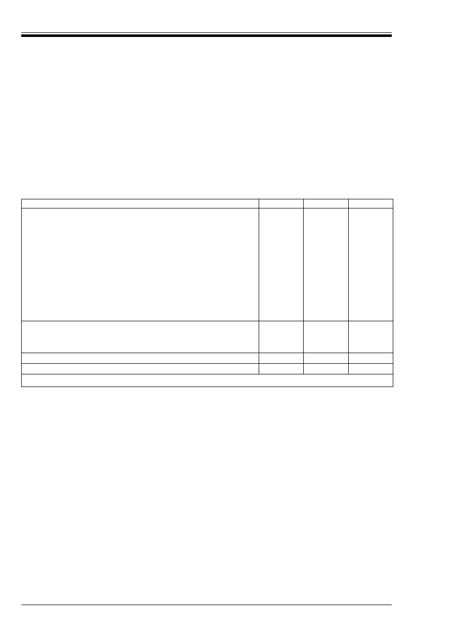
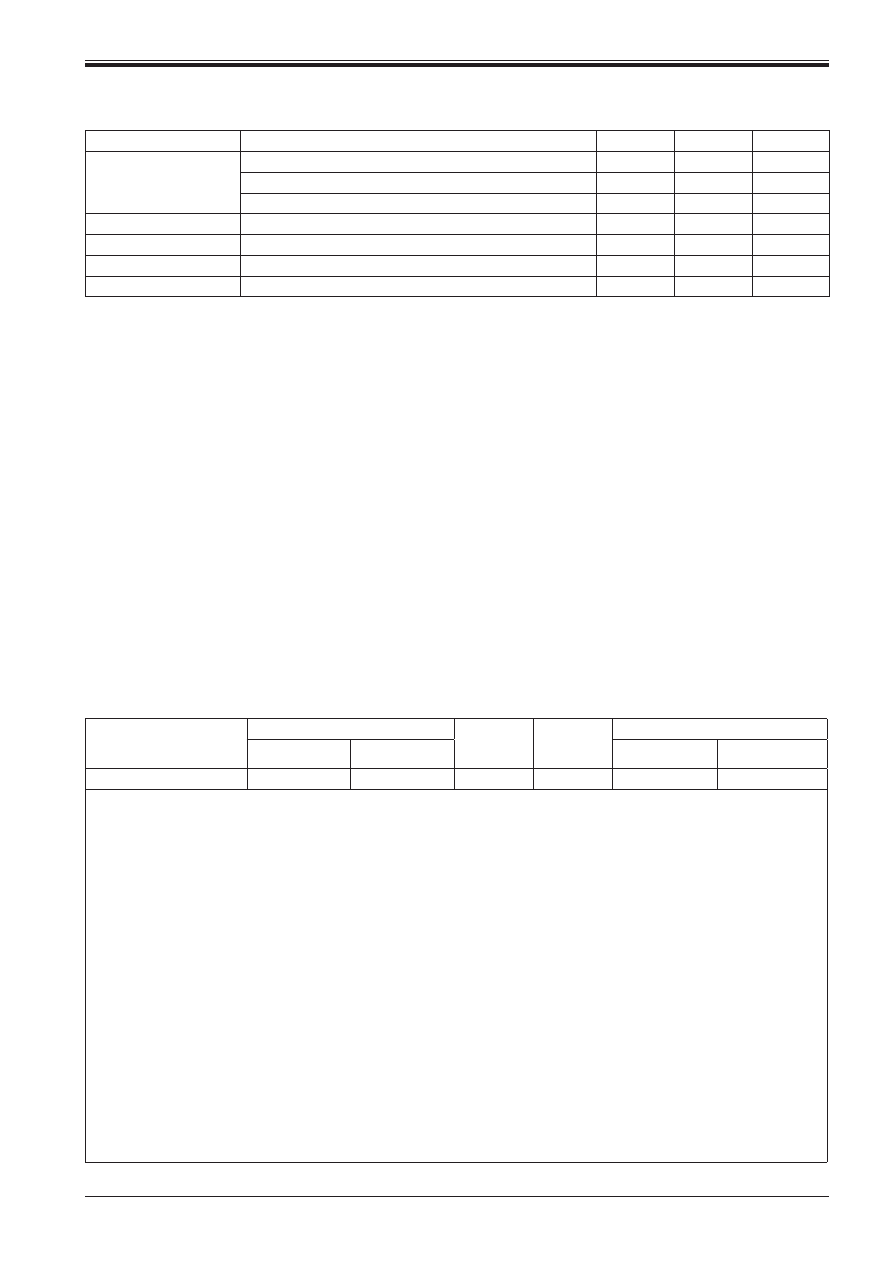
Table NA.2.1 — Indicative design working Life
Design working life
category
Indicative design
working life (years)
Examples
1
10
Temporary structures
a
2
10 to 30
Replaceable structural parts, e.g. gantry girders, bearings
3
15 to 25
Agricultural and similar structures
4
50
Building structures and other common structures, not
listed elsewhere in this table
5
120
Monumental building structures, highway and railway
bridges, and other civil engineering structures
a
Structures or parts of structures that can be dismantled with a view of being re-used should not be considered as temporary.
Licensed copy: BSI USER 06 Document Controller, Midmac Contracting Co. W.L.L, Version correct as of 05/06/2011 15:27, (c) BSI
NA.2.2 Nationally determined parameters for buildings
NA.2.2.1 Clause A.1.2.1 (1)
a) All effects of actions that can exist simultaneously should be considered together in combination of
actions.
b) With regard to Note 2 of Clause A.1.2.1 (1) of EN 1990 no modifications are allowed through the
National Annex for A1.2.1 (2) and (3).
NA.2.2.2 Clause A.1.2.2
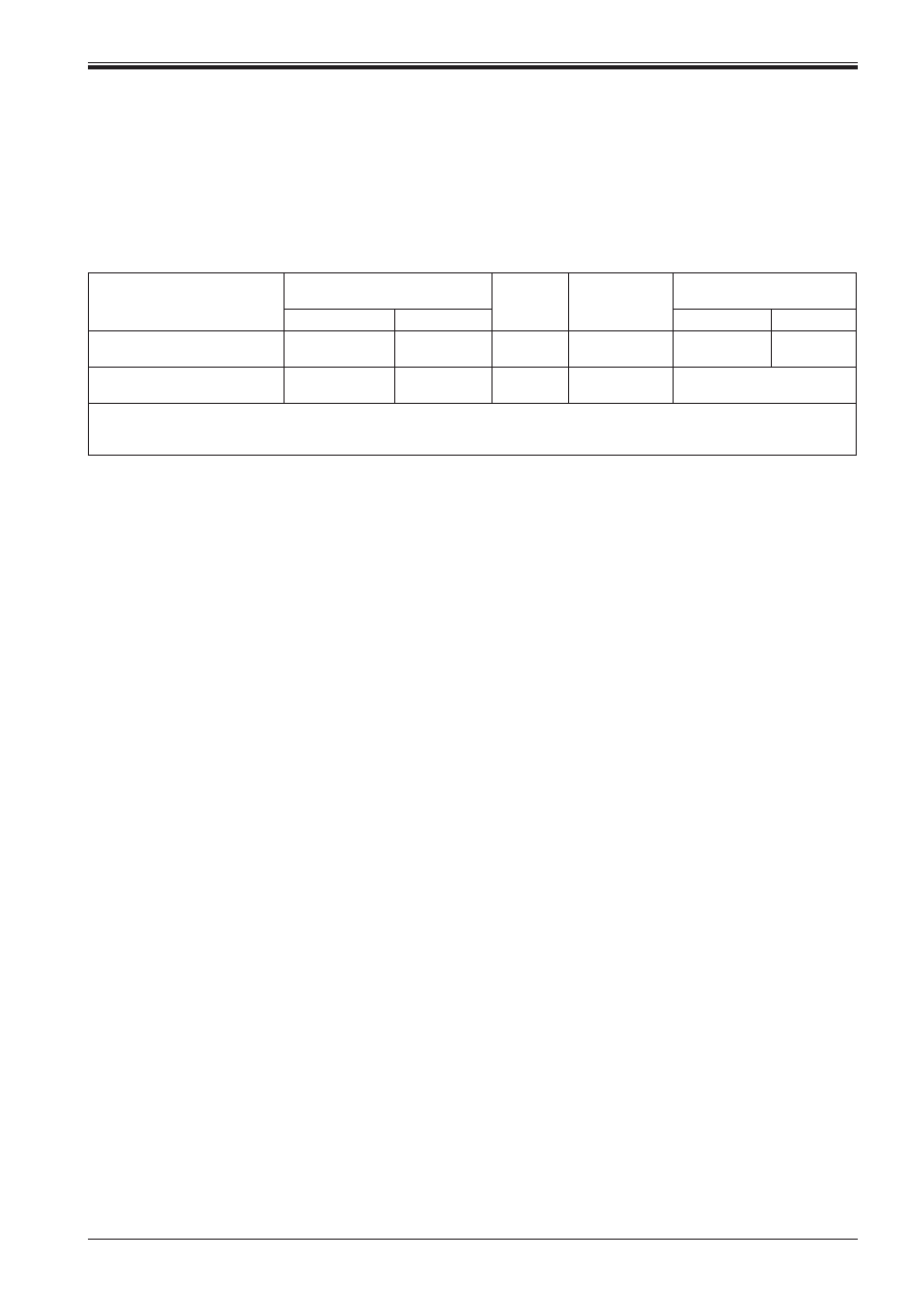
Table NA.A1.1 provides values for the symbols of Table A1.1 of EN 1990.
Table NA.A1.1 — Values of Ó factors for buildings
NA.2.2.3 Clause A.1.3
NA.2.2.3.1 Values for the symbols ¾ of Table A1.2 (A)
Table NA.A1.2 (A) provides the values for the symbols ¾ of Table A1.2 (A). The values chosen are:
¾
Gj,sup
= 1,10
¾
Gj,inf
= 0,90
¾
Q,1
= 1,50 where unfavourable (0 where favourable)
¾
Q,i
= 1,50 where unfavourable (0 where favourable)
NOTE For Ó values see Table A1.1 (BS).
Action
Ó
0
Ó
1
Ó
2
Imposed loads in buildings, category (see EN 1991-1.1)
Category A: domestic, residential areas
0,7
0,5
0,3
Category B: office areas
0,7
0,5
0,3
Category C: congregation areas
0,7
0,7
0,6
Category D: shopping areas
0,7
0,7
0,6
Category E: storage areas
1,0
0,9
0,8
Category F: traffic area,
vehicle weight k 30 kN
0,7
0,7
0,6
Category G: traffic area,
30 kN < vehicle weight k 160 kN
0,7
0,5
0,3
Category H: roofs
0,7
0
0
Snow loads on buildings (see EN 1991-3)
— for sites located at altitude H > 1 000 m a.s.l.
0,70
0,50
0,20
— for sites located at altitude H k1 000 m a.s.l.
0,50
0,20
0
Wind loads on buildings (see EN 1991-1-4)
0,5
0,2
0
Temperature (non-fire) in buildings (see EN 1991-1-5)
0,6
0,5
0
a
See also EN 1991-1-1: Clause 3.3.2 (1)
NA to BS EN 1990:2002+A1:2005
© BSI 2009
3
Licensed copy: BSI USER 06 Document Controller, Midmac Contracting Co. W.L.L, Version correct as of 05/06/2011 15:27, (c) BSI

Table NA.A1.2 (A) — Design values of actions (EQU) (Set A)
NA.2.2.3.2 Values for the symbols ¾ and ß of Table A1.2 (B)
Table NA.A1.2 (B) provides the values for the symbols ¾ and ß of Table A1.2 (B). The values chosen are:
¾
Gj,sup
= 1,35
¾
Gj,inf
= 1,00
¾
Q,1
= 1,50 where unfavourable (0 where favourable)
¾
Q,i
= 1,50 where unfavourable (0 where favourable)
ß = 0,925
NOTE For Ó values see Table NA.A1.1.
Persistent and
transient design
situations
Permanent actions
Leading variable
action
Accompanying variable actions
Unfavourable
Favourable
Main (if any)
Others
(Eq. 6.10)
1,10 G
kj,sup
0,90 G
kj,inf
1,5 Q
k,1
(0 when
favourable)
1,5Ó
0,i
Q
k,i
(0 when
favourable)
a
Variable actions are those considered in Table NA.A1.1.
In cases where the verification of static equilibrium also involves the resistance of structural members, as an alternative to two
separate verifications based on Tables NA.A1.2 (A) and A1.2 (B), a combined verification, based on Table NA.A1.2 (A), should be
adopted, with the following set of values.
¾
Gj,sup
= 1,35
¾
Gj,inf
= 1,15
¾
Q,1
= 1,50 where unfavourable (0 where favourable)
¾
Q,i
= 1,50 where unfavourable (0 where favourable)
provided that applying ¾
Gj,inf
= 1,00 both to the favourable part and to the unfavourable part of permanent actions does not give a
more unfavourable effect.
NA to BS EN 1990:2002+A1:2005
4
© BSI 2009
Licensed copy: BSI USER 06 Document Controller, Midmac Contracting Co. W.L.L, Version correct as of 05/06/2011 15:27, (c) BSI
Table NA.A1.2 (B) — Design values of actions (STR/GEO) (Set B)
Persistent
and transient
design
situations
Permanent actions
Leading
variable
action
Accompanying variable
actions
Persistent
and
transient
design
situations
Permanent actions
Leading
variable
action
Accompanying variable
actions
Unfavourable Favourable
Main (if
any)
Others
Unfavourable
Favourable
Action
Main
Others
(Eq. 6.10)
1,35G
kj,sup
1,00G
kj,inf
1,5Q
k,1
1,5
Ó0,1
Q
k,i
(Eq. 6.10a) 1,35G
kj,sup
1,00G
kj,inf
1,5
Ó0,1
Q
k,1
1,5
Ó0,1
Q
k,i
(Eq. 6.10b) 0,925*1,35G
kj,sup
1,00G
kj,inf
1,5Q
k,1
1,5
Ó0,1
Q
k,i
NOTE 1 Either expression 6.10, or expression 6.10a together with and 6.10b may be made, as desired.
NOTE 2 The characteristic values of all permanent actions from one source are multiplied by ¾
G,sup
if the total resulting action effect is unfavourable and ¾
G,inf
if the total resulting action
effect is favourable. For example, all actions originating from the self weight of the structure may be considered as coming from one source; this also applies if different materials are
involved.
NOTE 3 For particular verifications, the values for ¾
G
and ¾
Q
may be subdivided into ¾
g
and ¾
q
and the model uncertainty factor ¾
sd
. A value of ¾
sd
in the range 1,05 to 1,15 can be used in
most common cases and can be modified in the National Annex.
NOTE 4 When variable actions are favourable Q
k
should be taken as 0.
a
Variable actions are those considered in Table NA.A1.1.
NA to BS EN 1990:2002
+A1:2005
© BSI 2009
5
Licensed copy: BSI USER 06 Document Controller, Midmac Contracting Co. W.L.L, Version correct as of 05/06/2011 15:27, (c) BSI
NA.2.2.3.3 Values for the symbols ¾ of Table A1.2 (C)
Table NA.A1.2 (C) provides the values for the symbols ¾ of Table A1.2 (C). The values chosen are:
¾
Gj,sup
= 1,00
¾
Gj,inf
= 1,00
¾
Q,1
= 1,30 where unfavourable (0 where favourable)
¾
Q,i
= 1,30 where unfavourable (0 where favourable)
NOTE For Ó values see Table NA.A1.1.
Table NA.A1.2 (C) — Design values of actions (STR/GEO) (Set C)
NA.2.2.4 Clause A.1.3.1 (5)
Approach 1 should be used for the design of buildings in the UK.
NA.2.2.5 Clause A.1.3.2
Table NA.A1.3 provides the values for the symbols of Table A1.3 of EN 1990. All ¾ factors are equal to 1,00.
Coefficient Ó
11
is selected for the main accompanying variable action for the accidental design situation.
NOTE For Ó values see Table NA.A1.1.
Table NA.A1.3 — Design values of actions for use in accidental and seismic combinations
of actions
Persistent and
transient design
situation
Permanent actions
Leading variable
action
Accompanying variable actions
Unfavourable
Favourable
Main (if any)
Others
(Eq 6.10)
1,0 G
kj,sup
1,0G
kj,inf
1,3Q
k,1
(0 when
favourable)
1,3Ó
0,i
Q
k,i
(0 when
favourable)
a
Variable actions are those considered in Table NA.A1.1.
Design situation
Permanent actions
Leading
accidental or
seismic action
Accompanying variable actions
Unfavourable
Favourable
Main (if any)
Others
Accidental
(Eq 6.11a/b)
G
kj,sup
G
kj,inf
A
d
Ó
11
Q
k,1
Ó
2,i
Q
k,i
Seismic
(Eq 6.12a/b)
G
kj,sup
G
kj,inf
¾
1
A
Ek
or A
Ed
Ó
2,i
Q
k,i
a
The seismic design situation should be used only when specified by the client. See also Eurocode 8.
b
Variable actions are those considered in Table NA.A1.1.
NA to BS EN 1990:2002+A1:2005
6
© BSI 2009
Licensed copy: BSI USER 06 Document Controller, Midmac Contracting Co. W.L.L, Version correct as of 05/06/2011 15:27, (c) BSI

© BSI 2009
7
NA to BS EN 1990:2002+A1:2005
NA.2.2.6 Clause A1.4.2
Clause A1.4.2 of EN 1990, states that the serviceability criteria should be specified for each project and
agreed with the client. In the absence of specific requirements in EN 1992 to EN 1999 or their National
Annexes it is recommended that the following Combination of Action expressions are used with particular
serviceability requirements.
• For function and damage to structural and non-structural elements (e.g. partition walls etc.) the
characteristic combination (i.e. expression 6.14b of EN 1990).
• For comfort to user, use of machinery, avoiding ponding of water etc. the frequent combination
(i.e. expression 6.15b of EN 1990).
• For appearance of the structure the quasi-permanent combination (i.e. expression 6.15c of EN 1990.
Separate consideration should be given to serviceability related to appearance and that related to user
comfort which may be affected by structural deformation or vibration.
!
NA.2.3 Nationally determined parameters for bridges
NA.2.3.1 General [BS EN 1990:2002+A1:2005, A2.1.1(1), Note 3]
See
NA.2.1.1.
NA.2.3.2 General [BS EN 1990:2002+A1:2005, A2.2.1(2), Note 1]
Combinations involving actions that are outside the scope of BS EN 1991 (all parts) may be determined for
the individual project taking account of the general probability of the simultaneous occurrence of different
load components following the principles given in BS EN 1990:2002+A1:2005.
NA.2.3.3 Combination rules for road bridges [BS EN 1990:2002+A1:2005, A2.2.2]
NA.2.3.3.1 A2.2.2(1), Note
Infrequent combinations of actions need not be used.
NA.2.3.3.2 A2.2.2(3), Note
The combination rules for special vehicles with normal traffic are given in NA to BS EN 1991-2:2003. The
values of y and c factors given in this National Annex should be used.
NA.2.3.3.3 A2.2.2(4), Note
Snow loads may generally be ignored in the UK, see NA to BS EN 1991-1-3. Special cases where snow
loads have to be combined with groups gr1a and gr1b in combinations of actions may be determined for
the individual project.
NA.2.3.3.4 A2.2.2(6), Note
The combination of wind and thermal actions may generally be ignored in the UK. In special cases rules
for the combination of wind and thermal actions may be determined for the individual project.
NA.2.3.4 Combination rules for footbridges [BS EN 1990:2002+A1:2005, A2.2.3]
NA.2.3.4.1 A2.2.3(2), Note
The combination of wind and thermal actions may generally be ignored in the UK. In special cases rules
for the combination of wind and thermal actions may be determined for the individual project.
NA.2.3.4.2 A2.2.3(3), Note
Snow loads may generally be ignored in the UK, see NA to BS EN 1991-1-3, except for footbridges that are
provided with a roof.
In combinations of loads including snow loads the groups of loads gr1 and gr2 should be applied without
reduction of any of the component loads.
Other special cases where snow loads have to be combined with groups gr1 and gr2 in combinations of
actions may be determined for the individual project.
Licensed copy: BSI USER 06 Document Controller, Midmac Contracting Co. W.L.L, Version correct as of 05/06/2011 15:27, (c) BSI
8
© BSI 2009
NA to BS EN 1990:2002+A1:2005
NA.2.3.4.3 A2.2.3(4), Note
Specific combinations of actions for footbridges on which pedestrian and cycle traffic is fully protected from
all types of bad weather may be determined as appropriate for the individual project.
NA.2.3.5 Combination rules for railway bridges [BS EN 1990:2002+A1:2005, A2.2.4]
NA.2.3.5.1 A2.2.4(1), Note
Snow loads may generally be ignored in the UK, see NA to BS EN 1991-1-3. Special cases (for example
railway bridges with a roof) where snow loads have to be combined with rail traffic in combinations of
actions may be determined for the individual project.
NA.2.3.5.2 A2.2.4(4), Note
The limit of maximum peak velocity pressure q
p
(z), derived from the maximum wind speed that is
compatible with rail traffic for determination of F
W
**, is given in NA to BS EN 1991-1-4.
NA.2.3.6 Values of y factors [BS EN 1990:2002+A1:2005, A2.2.6]
NA.2.3.6.1 A2.2.6(1), Note 1
Table NA.A2.1 gives recommended values of y factors for road bridges to be used instead of Table A2.1 of
BS EN 1990:2002+A1:2005.
Table NA.A2.2 gives recommended values of y factors for footbridges to be used instead of Table A2.2 of
BS EN 1990:2002+A1:2005.
The recommended values of y factors for railway bridges given in Table A2.3 of BS EN 1990:2002+A1:2005
should be used.
NA.2.3.6.2 A2.2.6(1), Note 2
The infrequent value of actions defined in BS EN 1990:2002+A1:2005,
4.1.3 Note 2 should not be
considered.
NA.2.3.6.3 A2.2.6(1), Note 3
Where relevant, representative values of water actions F
wa
should be determined for the individual project.
Table NA.A2.1 – Recommended values of y factors for road bridges
Action
Group of
Loads
Load components
y
0
y
1
y
2
Traffic loads
gr1a
a
TS
0,75
0,75
0
UDL
0,75
0,75
0
Footway and cycle-track loads
0,40
0,40
0
gr1b
a
Single axle
0
0,75
0
gr2
Horizontal forces
0
0
0
gr3
Pedestrian loads
0
0,40
0
gr4
Crowd loading
0
—
b
0
gr5
Vertical forces from SV and SOV vehicles
0
—
b
0
gr6
Horizontal forces from SV and SOV vehicles
0
0
0
Wind forces
F
Wk
Persistent design situations
0,50
0,20
0
During execution
0,80
—
0
F
*
W
During execution
1,0
—
0
Thermal actions
T
k
0,60
0,60
0,50
Snow loads
Q
Sn,k
0,80
—
—
Construction loads
Q
c
1,0
1,0
a
The recommended values of y
0
, y
1
, y
2
for gr1a and gr1b are given for roads with traffic corresponding to adjusting factors a
Qi
, a
qi
,
a
qr
and b
Q
defined in the NA to BS EN 1991-2:2003.
b
The frequent values of load groups gr4 and gr5 do not need to be considered in accordance with BS EN 1991-2:2003,
4.5.2.
NOTE The y
0
factors specified for a group of loads apply to all the component actions in that group, except for gr1a where they are
individually specified. The y
1
and y
2
factors always apply to individual components of loading and the values for a given
component are the same in all load groups in which the component occurs.
Licensed copy: BSI USER 06 Document Controller, Midmac Contracting Co. W.L.L, Version correct as of 05/06/2011 15:27, (c) BSI
© BSI 2009
9
NA to BS EN 1990:2002+A1:2005
Table NA.A2.2 – Recommended values of y factors for footbridges
Action
Symbol
y
0
y
1
y
2
Traffic loads
gr1
0,40
0,40
0
Q
fwk
0
0
0
gr2
0
0
0
Wind forces
F
Wk
0,3
0,2
0
Thermal actions
T
k
0,60
0,60
0,50
Snow loads
Q
Sn,k
(during execution)
0,80
—
0
Construction loads
Q
c
1,0
—
1,0
NA.2.3.7 Ultimate limit states – Design values of actions in persistent and transient design
situations [BS EN 1990:2002+A1:2005, A2.3.1]
NA.2.3.7.1 A2.3.1(1)
For the design of bridges the combination of actions should be based on equation 6.10. Table NA.A2.4(A),
Table NA.A2.4(B) and Table NA.A2.4(C) give design values of actions for the persistent and
transient design situations to be used instead of Tables A2.4(A), Table A2.4(B) and Table A2.4(C) of
BS EN 1990:2002+A1:2005.
NA.2.3.7.2 A2.3.1(5)
Approach 1 should be used for the design of structural members involving geotechnical actions and the
resistance of the ground.
NA.2.3.7.3 A2.3.1(7)
Forces due to ice pressure on bridge piers may generally be ignored in the UK. For special cases where it
is appropriate to take them into account, the requirements should be determined for the individual project.
NA.2.3.7.4 A2.3.1(8)
In the case where c
P
values for prestressing actions are not provided in the relevant
design Eurocodes, these values should be determined for the individual project.
Table NA.A2.4(A) – Design values of actions (EQU) (Set A)
Persistent and
transient design
situation
Permanent actions
Prestress
Leading
variable
action
Accompanying variable actions
Unfavourable
Favourable
Main (if any)
Others
(Eq. 6.10)
c
Gj
,sup
G
kj
,sup
c
Gj
,inf
G
kj
,inf
c
P
P
c
Q
,1
Q
k
,1
c
Q
,i
y
0,i
Q
k
,i
NOTE 1 For
persistent design situations the recommended set of values for c are:
Permanent actions (contributions from the following components should be combined as appropriate)
Concrete self weight
c
G,sup
= 1,05
c
G,inf
= 0,95
Steel self weight
c
G,sup
= 1,05
c
G,inf
= 0,95
Super-imposed dead
c
G,sup
= 1,05
c
G,inf
= 0,95
Road surfacing
c
G,sup
= 1,05
c
G,inf
= 0,95
Ballast
c
G,sup
= 1,05
c
G,inf
= 0,95
Weight of soil
c
G,sup
= 1,05
c
G,inf
= 0,95
Self weight of other materials listed in
BS EN 1991-1-1:2002, Tables A.1-A.6
c
G,sup
= 1,05
c
G,inf
= 0,95
Prestressing
c
P
as defined in the relevant design Eurocode or for the individual project
Variable actions
Road traffic actions
(gr1a, gr1b, gr2, gr5, gr6)
c
Q
= 1,35
(0 where favourable)
Pedestrian actions (gr3, gr4)
c
Q
= 1,35
(0 where favourable)
Rail traffic actions (LM71, SW/0, HSLM)
c
Q
= 1,45
(0 where favourable)
Rail traffic actions (SW/2 and other load
models representing controlled exceptional
traffic)
c
Q
= 1,40
(0 where favourable)
Rail traffic actions (Real trains)
c
Q
= 1,70
(0 where favourable)
Wind actions (see Note 5)
c
Q
= 1,70
(0 where favourable)
Thermal actions (see Note 6)
c
Q
= 1,55
(0 where favourable)
Licensed copy: BSI USER 06 Document Controller, Midmac Contracting Co. W.L.L, Version correct as of 05/06/2011 15:27, (c) BSI

10
© BSI 2009
NA to BS EN 1990:2002+A1:2005
NOTE 2 For self-weight of water, ground-water pressure and other actions dependent on the level of water, no partial factor is
specified in this National Annex. The design value of such actions may be directly assessed in accordance with
2.4.6.1(2)P and
2.4.6.1(6)P of BS EN 1997-1:2004. Alternatively a safety margin may be applied to the characteristic water levelas set out in
2.4.6.1(8) of BS EN 1997-1:2004. Partial factors for such actions may be determined for the individual project (see 2.4.7.3.2(2) of
BS EN 1997-1:2004).
NOTE 3 The design value of earth pressures should be based on the design value of the actions giving rise to the earth pressure.
In some cases supplementary model factors may be required when evaluating horizontal earth pressures (see the National Annex
to BS EN 1997-1:2004).
NOTE 4 For all other actions, not covered in NOTES 1 to 3, the partial factors should be determined for the individual project.
NOTE 5 The specified value of c
Q
has been determined for cases where the design working life is 120 years and is used with the
characteristic value of wind actions given in BS EN 1991-1-4:2005 which corresponds to a mean return period of 50 years. If
the duration of the relevant design situation is taken into account directly using BS EN 1991-1-4:2005,
4.2(2) a reduced value of
c
Q
= 1,55 may be used for unfavourable actions. For persistent design situations, the duration of the design situation may be
taken into account by adjusting the wind velocity for a mean return period equal to the design working life but not less than 50
years. For transient design situations, see also BS EN 1991-1-6:2005,
3.1(5).
NOTE 6 The specified value of c
Q
has been determined for cases where the design working life is 120 years and is used with the
characteristic value of thermal actions given in BS EN 1991-1-5:2003 which corresponds to a mean return period of 50 years.
If the duration of the relevant design situation is taken into account directly using BS EN 1991-1-5:2003,
A.2 a reduced value of
c
Q
= 1,45 may be used for unfavourable actions. For persistent design situations, the duration of the design situation may be
taken into account by adjusting the shade air temperature for a mean return period equal to the design working life but not less
than 50 years. For transient design situations, see also BS EN 1991-1-6:2005,
3.1(5).
NOTE 7 Partial factors for actions involving the aerodynamic effects of wind on bridges should be determined for the individual
project. Guidance on the factors to be considered may be found in PD 6688-1-4.
NOTE 8 The characteristic values of all unfavourable permanent actions are multiplied by c
G,sup
and the characteristic values of
all favourable permanent actions are multiplied by c
G,inf
irrespective of whether they arise from a single source, see
BS EN 1990:2002+A1:2005,
6.4.3.1(4). See also BS EN 1990:2002+A1:2005, A.2.3.1(2). For design situations involving buried
structures, where the stability is highly sensitive to the interaction between the structure and the soil, c
G,sup
should be applied to
unfavourable permanent action effects and c
G,inf
should be applied to favourable permanent action effects.
NOTE 9 For verification of uplift of bearings of continuous bridges or in cases whether the verification of static equilibrium also
involves the resistance of structural elements or the ground c values may be determined for the individual project as an
alternative to separate verifications based on Tables NA.A2.4(A)-(C), see also BS EN 1990:2002+A1:2005,
6.4.3.1(4).
NOTE 10 For transient design situations, during which there is a loss of static equilibrium, Q
k,1
represents the dominant
destabilising variable action and Q
k,i
represents the relevant accompanying destabilising variable actions.
During execution, if the construction process is adequately controlled, the recommended set of values for c for the persistent
design situations given above may be used with the exceptions set out below:
(A) Where a counterweight is used, the variability of its characteristics may be taken into account, for example, by one or both of
the following rules:
- applying a partial factor c
G,Inf
= 0,8 where the self weight is not well defined (e.g. containers);
- by considering a variation of its project-defined location, with a value to be specified proportionately to the dimensions of
the bridge, where the magnitude of the counterweight is well defined. For steel bridges during launching, the variation of the
counterweight location is often taken equal to ±1 m.
(B) Where loss of equilibrium could result in multiple fatalities (for example bridges constructed over railways or motorways),
partial factors for permanent actions affecting stability (c
G,sup
and c
G,inf
), should be increased to 1,15 and decreased to 0,85
respectively.
Table NA.A2.4(A) (continued)
Licensed copy: BSI USER 06 Document Controller, Midmac Contracting Co. W.L.L, Version correct as of 05/06/2011 15:27, (c) BSI

© BSI 2009
11
NA to BS EN 1990:2002+A1:2005
Table NA.A2.4(B) – Design values of actions (STR/GEO) (Set B)
Persistent and
transient design
situation
Permanent actions
Prestress
Leading
variable
action
Accompanying variable
actions
Unfavourable
Favourable
Main Others
(Eq. 6.10)
c
Gj
,sup
G
kj
,sup
c
Gj
,inf
G
kj
,inf
c
P
P
c
Q
,1
Q
k
,1
c
Q
,i
y
0,i
Q
k
,i
NOTE 1 For
persistent design situations the recommended set of values for c are:
Permanent Actions (contributions from the following components should be combined as appropriate)
Concrete self weight
c
G,sup
= 1,35
c
G,inf
= 0,95
Steel self weight
c
G,sup
= 1,20
c
G,inf
= 0,95
Super-imposed dead
c
G,sup
= 1,20
c
G,inf
= 0,95
Road surfacing
c
G,sup
= 1,20
c
G,inf
= 0,95
Ballast
c
G,sup
= 1,35
c
G,inf
= 0,95
Weight of soil
c
G,sup
= 1,35
c
G,inf
= 0,95
Self weight of other materials listed in
BS EN 1991-1-1:2002 Tables A.1–A.6
c
G,sup
= 1,35
c
G,inf
= 0,95
Settlement (linear structural analysis)
c
G,set sup
= 1,20
c
G,set,inf
= 0,00
Settlement (nonlinear structural analysis)
c
G,set,sup
= 1,35
c
Gset,,inf
= 0,00
Prestressing
c
P
as defined in the relevant design Eurocode or for the individual project
Variable actions
Road traffic actions (gr1a, gr1b, gr2, gr5, gr6)
c
Q
= 1,35
(0 where favourable)
Pedestrian actions (gr3, gr4)
c
Q
= 1,35
(0 where favourable)
Rail traffic actions (LM71, SW/0, HSLM)
c
Q
= 1,45
(0 where favourable)
Rail traffic actions (SW/2 and other load
models representing controlled exceptional
traffic)
c
Q
= 1,40
(0 where favourable)
Rail traffic actions (Real trains)
c
Q
= 1,70
(0 where favourable)
Wind actions (see Note 5)
c
Q
= 1,70
(0 where favourable)
Thermal actions (see Note 6)
c
Q
= 1,55
(0 where favourable)
NOTE 2 For self-weight of water, ground-water pressure and other actions dependent on the level of water, no partial factor is
specified in this National Annex. The design value of such actions may be directly assessed in accordance with
2.4.6.1(2)P and
2.4.6.1(6)P of BS EN 1997-1:2004. Alternatively a safety margin may be applied to the characteristic water level (see 2.4.6.1(8) of
BS EN 1997-1:2004). Partial factors for such actions may be determined for the individual project, but see
2.4.7.3.2(2) of
BS EN 1997-1:2004.
NOTE 3 The design value of earth pressures should be based on the design value of the actions giving rise to the earth pressure.
In some cases supplementary model factors may be required when evaluating horizontal earth pressures
(see NA to BS EN 1997-1:2004).
NOTE 4 For all other actions, not covered in NOTES 1 to 3, the partial factors should be determined for the individual project.
NOTE 5 The specified value of c
Q
has been determined for cases where the design working life is 120 years and is used with the
characteristic value of wind actions given in BS EN 1991-1-4:2005 which corresponds to a mean return period of 50 years. If the
duration of the relevant design situation is taken into account directly using BS EN 1991-1-4:2005,
4.2(2) a reduced value of
c
Q
= 1,55 may be used for unfavourable actions. For persistent design situations, the duration of the design situation may be taken
into account by adjusting the wind velocity for a mean return period equal to the design working life but not less than 50 years.
For transient design situations, see also BS EN 1991-1-6:2005,
3.1(5).
NOTE 6 The specified value of c
Q
has been determined for cases where the design working life is 120 years and is used with the
characteristic value of thermal actions given in BS EN 1991-1-5:2003 which corresponds to a mean return period of 50 years. If the
duration of the relevant design situation is taken into account directly using BS EN 1991-1-5:2005,
A.2 a reduced value of
c
Q
= 1,45 may be used for unfavourable actions. For persistent design situations, the duration of the design situation may be taken
into account by adjusting the shade air temperature for a mean return period equal to the design working life but not less than 50
years. For transient design situations, see also BS EN 1991-1-6:2005,
3.1(5).
NOTE 7 Partial factors for actions involving the aerodynamic effects of wind on bridges should be determined for the individual
project. Guidance on the factors to be considered may be found in PD 6688-1-4.
NOTE 8 The characteristic values of all permanent actions from one source may be multiplied by c
G,sup
if the total resulting action
effect from this source is unfavourable, and by c
G,inf
if the total resulting action effect from this source is favourable. However,
where a verification is very sensitive to variations in the magnitude of a permanent action from place to place and also involves the
resistance of structural elements or the ground, see Table NA.A2.4(A) Note 9. See also BS EN 1990:2002+A1:2005
6.4.3.1(4) and
A2.3.1(2).
NOTE 9 For particular verifications, the values of c
G
andc
Q
may be sub-divided into c
g
andc
q
and the model uncertainty factorc
Sd
. A
value of c
Sd
= 1,15 can be used except where otherwise determined for the individual project.
Licensed copy: BSI USER 06 Document Controller, Midmac Contracting Co. W.L.L, Version correct as of 05/06/2011 15:27, (c) BSI

12
© BSI 2009
NA to BS EN 1990:2002+A1:2005
Table NA.A2.4(C) – Design values of actions (STR/GEO) (Set C)
Persistent and
transient design
situation
Permanent actions
Prestress
Leading
variable
action
Accompanying variable
actions
Unfavourable
Favourable
Main (if any)
Others
(Eq. 6.10)
c
Gj
,sup
G
kj
,sup
c
Gj
,inf
G
kj
,inf
c
P
P
c
Q
,1
Q
k
,1
c
Q
,i
y
0,i
Q
k
,i
NOTE 1 For persistent design situations the recommended set of values for c are:
Permanent actions (contributions from the following components should be combined as appropriate)
Concrete self weight
c
G,sup
= 1,00
c
G,inf
= 1.00
Steel self weight
c
G,sup
= 1,00
c
G,inf
= 1.00
Super-imposed dead
c
G,sup
= 1,00
c
G,inf
= 1.00
Road surfacing
c
G,sup
= 1,00
c
G,inf
= 1.00
Ballast
c
G,sup
= 1,00
c
G,inf
= 1.00
Weight of soil
c
G,sup
= 1,00
c
G,inf
= 1.00
Self weight of other materials listed in
BS EN 1991-1-1:2002, Tables A.1—A.6
c
G,sup
= 1,00
c
G,inf
= 1.00
Settlement (linear structural analysis)
c
G,set sup
= 1,00
c
G,set,inf
= 0,00
Settlement (nonlinear structural analysis)
c
G,set sup
= 1,00
c
G,set,inf
= 0,00
Prestressing
c
P
as defined in the relevant design Eurocode or for the individual project
Variable actions
Road traffic actions
(gr1a, gr1b, gr2, gr5, gr6)
c
Q
= 1,15
(0 where favourable)
Pedestrian actions (gr3, gr4)
c
Q
= 1,15
(0 where favourable)
Rail traffic actions (LM71, SW/0,
HSLM)
c
Q
= 1,25
(0 where favourable)
Rail traffic actions (SW/2and other load
models representing controlled exceptional
traffic)
c
Q
= 1,20
(0 where favourable)
Rail traffic actions (Real trains)
c
Q
= 1,45
(0 where favourable)
Wind actions (see Note 5)
c
Q
= 1,45
(0 where favourable)
Thermal actions (see Note 6)
c
Q
= 1,30
(0 where favourable)
NOTE 2 For self-weight of water, ground-water pressure and other actions dependent on the level of water, no partial factor is
specified in this National annex. The design value of such actions may be directly assessed in accordance with
2.4.6.1(2)P and
2.4.6.1(6)P of BS EN 1997-1:2004. Alternatively a safety margin may be applied to the characteristic water level (see 2.4.6.1(8) of
BS EN 1997-1:2004). Partial factors for such actions may be determined for the individual project and agreed with the relevant
authority, but see
2.4.7.3.2(2) of BS EN 1997-1:2004.
NOTE 3 The design value of earth pressures should be based on the design value of the actions giving rise to the earth pressure.
In some cases supplementary model factors may be required when evaluating horizontal earth pressures, see
NA to BS EN 1997-1:2004.
NOTE 4 For all other actions, not covered in NOTES 1 to 3, the partial factors should be determined for the individual project.
NOTE 5 The specified value of c
Q
has been determined for cases where the design working life is 120 years and is used with the
characteristic value of wind actions given in BS EN 1991-1-4:2005 which corresponds to a mean return period of 50 years. If the
duration of the relevant design situation is taken into account directly using BS EN 1991-1-4:2005,
4.2(2) a reduced value of
c
Q
= 1,30 may be used for unfavourable actions. For persistent design situations, the duration of the design situation may be taken
into account by adjusting the wind velocity for a mean return period equal to the design working life but not less than 50 years.
For transient design situations, see also BS EN 1991-1-6:2005,
3.1(5).
NOTE 6 The specified value of c
Q
has been determined for cases where the design working life is 120 years and is used with the
characteristic value of thermal actions given in BS EN 1991-1-5:2003 which corresponds to a mean return period of 50 years.
If the duration of the relevant design situation is taken into account directly using BS EN 1991-1-5:2003,
A.2 a reduced value of
c
Q
= 1,20 may be used for unfavourable actions. For persistent design situations, the duration of the design situation may be taken
into account by adjusting the shade air temperature for a mean return period equal to the design working life but not less than
50 years. For transient design situations, see also BS EN 1991-1-6:2005,
3.1(5).
NOTE 7 Partial factors for actions involving the aerodynamic effects of wind on bridges should be determined for the individual
project. Guidance on the factors to be considered may be found in PD 6688-1-4.
NOTE 8 The characteristic values of all permanent actions from one source may be multiplied by c
G,sup
if the total resulting action
effect from this source is unfavourable, and by c
G,inf
if the total resulting action from this source is favourable. However, where a
verification is very sensitive to variations in the magnitude of a permanent action from place to place and also involves the
resistance of structural elements or the ground, see Table NA.A2.4(A) Note 9. See also BS EN 1990:2002+A1:2005,
6.4.3.1(4) and
A2.3.1(2).
NOTE 9 For particular verifications, the values of c
Q
may be sub-divided into c
q
and the model uncertainty factorc
Sd
. A value for
c
Sd
between 1,05 and 1,15, should be determined for the individual project.
Licensed copy: BSI USER 06 Document Controller, Midmac Contracting Co. W.L.L, Version correct as of 05/06/2011 15:27, (c) BSI
© BSI 2009
13
NA to BS EN 1990:2002+A1:2005
NA.2.3.8 Design values of actions in the accidental and seismic design situations
[BS EN 1990:2002+A1:2005, A2.3.2(1), Table A2.5]
All the partial factors c should be taken equal to 1.0 in using the design values of actions given in Table
NA.A.2.5. The values of y factors should be taken from Table NA.A2.1, Table NA.A2.2, or Table A.2.3 of
BS EN 1990:2002+A1:2005 as appropriate.
Table NA.A2.5 – Design values of actions for use in accidental and seismic combinations of
actions
Design situation
Permanent actions
Prestress
Accidental or
seismic action
Accompanying variable
actions
Unfavourable
Favourable
Main (if any)
Others
Accidental
A)
(BS EN
1990(A1):2005, Eq. 6.11a/b)
G
kj,sup
G
kj,inf
P A
d
y
1,1
Q
k,1
y
2,i
Q
k,i
Seismic
B)
(BS EN
1990(A1):2005, Eq. 6.12a/b)
G
kj,sup
G
kj,inf
P A
Ed
= c
I
A
Ek
y
2,i
Q
k,i
A)
In the case of accidental design situations, the main variable action may be taken with its frequent value with the
combination factor y
1
given in Table NA.A2.1, Table NA.A2.2, or Table A2.3 as appropriate.
B)
The seismic design situation should be used only when specified for the individual project (see BS EN 1998).
NA.2.3.9 Serviceability and other specific limit states – General [BS EN 1990:2002+A1:2005,
A2.4.1]
NA.2.3.9.1 A2.4.1(1) Note 1
All the partial factors c should be taken equal to 1.0 and the design values of actions given in Table A2.6 of
BS EN 1990:2002+A1:2005 for serviceability limit state should be used.
NA.2.3.9.2 A2.4.1(1) Note 2
The infrequent value of actions defined in BS EN 1990:2002+A1:2005,
4.1.3 Note 2 need not be considered.
NA 2.3.9.3 A2.4.1(2) Note
Serviceability requirements and criteria may be determined as appropriate for the individual project.
NA.2.3.10 Pedestrian comfort criteria (for serviceability) [BS EN 1990:2002+A1:2005, A2.4.3.2(1)]
The pedestrian comfort criteria should be as given in
NA.2.44 of NA to BS EN 1991-2:2003.
NA.2.3.11 Verifications regarding deformations and vibrations for railway bridges
[BS EN 1990:2002+A1:2005, A2.4.4]
NA.2.3.11.1 A2.4.4.1(1) Note 3 – General
Limits of deformation and vibration (frequency and acceleration) for temporary bridges should be deter-
mined for the individual project.
NA.2.3.11.2 A2.4.4.2.1(4) Note – Criteria for traffic safety – Vertical acceleration of the deck
The maximum peak values of bridge deck acceleration and the associated frequency limits should be
determined for the individual project.
NA.2.3.11.3 A2.4.4.2.2(2) Note – Criteria for traffic safety – Deck twist
The values of maximum twist (t) for track of any gauge should be determined for the individual project.
NA.2.3.11.4 A2.4.4.2.2(3) Note – Criteria for traffic safety – Deck twist
The recommended value for total track twist (t
T
) should be used.
NA.2.3.11.5 A2.4.4.2.3(1) Note – Criteria for traffic safety – Vertical deformation of the deck
Additional requirements for limiting vertical deformation for ballasted and non-ballasted bridges may be
determined for the individual project.
NA.2.3.11.6 A2.4.4.2.3(2) Note – Criteria for traffic safety – Vertical deformation of the deck
The limit of rotation at the ends of non-ballasted bridge decks should be determined for the individual
project.
Licensed copy: BSI USER 06 Document Controller, Midmac Contracting Co. W.L.L, Version correct as of 05/06/2011 15:27, (c) BSI

14
© BSI 2009
NA to BS EN 1990:2002+A1:2005
NA.2.3.11.7 A2.4.4.2.3(3) Note – Criteria for traffic safety – Vertical deformation of the deck
Additional limits for angular rotation at the ends of bridge decks in the vicinity of expansion devices and
switches and crossings, may be specified for the individual project.
NA.2.3.11.8 A2.4.4.2.4(2) Note – Criteria for traffic safety – Transverse deflection of the deck
The maximum differential transverse deflection at the top of the deck should be compatible with the
limits for maximum horizontal rotation and maximum change of radius of curvature, set out in
BS EN 1990:2002+A1:2005, Table A2.8.
NA.2.3.11.9 A2.4.4.2.4(2) Table A2.8 NOTE 3 – Maximum horizontal rotation and maximum change of
radius of curvature
The recommended values should be used.
NA.2.3.11.10 A2.4.4.2.4(3) Note – First natural frequency of lateral vibration
The value for the first natural frequency of lateral vibration should be determined for the individual
project.
NA.2.3.11.10 A2.4.4.3.2(6) Note – Limiting values for the maximum vertical deflection for passenger
comfort – Deflection criteria for checking passenger comfort
The requirements for passenger comfort should be determined for the individual project."
NA.3 Guidance on using the informative annexes B, C and D
NA.3.1 For buildings
NA.3.1.1 Annex B
Annex B may be used. If used it should be in accordance with the full reliability based approach described
in Annex C of EN 1990.
Annex B provides informative guidance relating to a number of the assumptions (see Clause 1.3 of
EN 1990), and in particular on quality management and control measures in design, detailing and
execution which aim to eliminate failures due to gross errors, and to achieve the resistance assumed in the
design.
For this purpose the use of Clauses B4 and B5 of this Annex are recommended.
NA.3.1.2 Annex C
Annex C may be used for calibration purposes, and for cases of actions not covered by EN 1991.
NA.3.1.3 Annex D
Annex D may be used.
!
NOTE Guidance on using Annexes B, C and D for cranes and machinery, silos and tanks, towers and masts, etc. will be given
when available."
!
NA.3.2 For bridges
NA.3.2.1 Annex B
Annex B may be used where appropriate subject to the following modifications.
With reference to
B3 of Annex B, bridges should normally be treated as medium consequence structures
(consequence class 2). Design for a lower or higher consequence class may be considered for an individual
project.
In the absence of a project-specific requirement, the minimum values for reliability index given in Table B2
may be used where a probabilistic design approach is adopted (see
NA.3.2.2 of this National Annex).
NA.3.2.2 Annex C
With regard to
3.5(5) of BS EN 1990:2002+A1:2005, a design based on probabilistic methods may be
considered for an individual project. Where a probabilistic approach is adopted, Annex C may be used
where appropriate and subject to the following modification:
Licensed copy: BSI USER 06 Document Controller, Midmac Contracting Co. W.L.L, Version correct as of 05/06/2011 15:27, (c) BSI

© BSI 2009
15
NA to BS EN 1990:2002+A1:2005
C7 of Annex C should only be used to derive design values for cases not explicitly covered by this National
Annex.
NA.3.2.3 Annex D
Annex D may be used where appropriate."
NA.4 Reference to non-contradictory complementary information (NCCI) and
Bibliography
NA.4.1 For buildings
None.
!
NOTE References to any non-contradictory complementary information for cranes and machinery, silos and tanks, towers and
masts, etc. will be given when available.
NA.4.2 For bridges
PD 6704, Guidance on the design of structures to the UK National Annex to BS EN 1990
1)
PD 6688-1-4, Background information to the UK National Annex to BS EN 1991-1-4 and additional
guidance
1)
PD 6698, Recommendations for the design of structures for earthquake resistance to BS EN 1998
1)
Bibliography
BS EN 1991 (all parts), Eurocode 1 – Actions on structures
BS EN 1997-1:2004, Eurocode 7 – Geotechnical design – Part 1: General rules
NA to BS EN 1991-1-1:2002, UK National Annex to Eurocode 1 – Actions on structures – Part 1-1: General
actions – Densities, self-weight, imposed loads for buildings
NA to BS EN 1991-1-3, UK National Annex to Eurocode 1 – Actions on structures – Part 1-3: General
actions – Snow loads
NA to BS EN 1991-1-4:2005, UK National Annex to Eurocode 1 – Actions on structures – Part 1-4: General
actions – Wind actions
NA to BS EN 1991-1-5:2003, UK National Annex to Eurocode 1 – Actions on structures – Part 1-5: General
actions – Thermal actions
NA to BS EN 1991-1-6:2005, UK National Annex to Eurocode 1 – Actions on structures – Part 1-6: General
actions – Actions during execution
NA to BS EN 1991-2:2003, UK National Annex to Eurocode 1 – Actions on structures – Part 2: Traffic loads
on bridges
NA to BS EN 1997-1:2004, UK National Annex to Eurocode 7 – Geotechnical design – Part 1: General
rules"
1)
In preparation.
Licensed copy: BSI USER 06 Document Controller, Midmac Contracting Co. W.L.L, Version correct as of 05/06/2011 15:27, (c) BSI

BSI Group
Headquarters 389
Chiswick High Road,
London, W4 4AL, UK
Tel +44 (0)20 8996 9001
Fax +44 (0)20 8996 7001
www.bsigroup.com/
standards
BSI - British Standards Institution
BSI is the independent national body responsible for preparing British
Standards. It presents the UK view on standards in Europe and at the
international level. It is incorporated by Royal Charter.
Revisions
British Standards are updated by amendment or revision. Users of British
Standards should make sure that they possess the latest amendments or
editions.
It is the constant aim of BSI to improve the quality of our products and services.
We would be grateful if anyone finding an inaccuracy or ambiguity while using
this British Standard would inform the Secretary of the technical committee
responsible, the identity of which can be found on the inside front cover. Tel:
+44 (0)20 8996 9000. Fax: +44 (0)20 8996 7400.
BSI offers members an individual updating service called PLUS which ensures
that subscribers automatically receive the latest editions of standards.
Buying standards
Orders for all BSI, international and foreign standards publications should be
addressed to Customer Services. Tel: +44 (0)20 8996 9001. Fax: +44 (0)20 8996
7001 Email: orders@bsigroup.com You may also buy directly using a debit/credit
card from the BSI Shop on the Website http://www.bsigroup.com/shop
In response to orders for international standards, it is BSI policy to supply the
BSI implementation of those that have been published as British Standards,
unless otherwise requested.
Information on standards
BSI provides a wide range of information on national, European and
international standards through its Library and its Technical Help to Exporters
Service. Various BSI electronic information services are also available which
give details on all its products and services. Contact Information Centre. Tel:
+44 (0)20 8996 7111 Fax: +44 (0)20 8996 7048 Email: info@bsigroup.com
Subscribing members of BSI are kept up to date with standards developments
and receive substantial discounts on the purchase price of standards. For details
of these and other benefits contact Membership Administration. Tel: +44 (0)20
8996 7002 Fax: +44 (0)20 8996 7001 Email: membership@bsigroup.com
Information regarding online access to British Standards via British Standards
Online can be found at http://www.bsigroup.com/BSOL
Further information about BSI is available on the BSI website at http://
www.bsigroup.com
Copyright
Copyright subsists in all BSI publications. BSI also holds the copyright, in the
UK, of the publications of the international standardization bodies. Except as
permitted under the Copyright, Designs and Patents Act 1988 no extract may
be reproduced, stored in a retrieval system or transmitted in any form or by any
means – electronic, photocopying, recording or otherwise – without prior written
permission from BSI.
This does not preclude the free use, in the course of implementing the standard,
of necessary details such as symbols, and size, type or grade designations. If
these details are to be used for any other purpose than implementation then the
prior written permission of BSI must be obtained.
Details and advice can be obtained from the Copyright and Licensing Manager.
Tel: +44 (0)20 8996 7070 Email: copyright@bsigroup.com
NA to
BS EN 1990:
2002
+A1:2005
Licensed copy: BSI USER 06 Document Controller, Midmac Contracting Co. W.L.L, Version correct as of 05/06/2011 15:27, (c) BSI
Document Outline
Wyszukiwarka
Podobne podstrony:
Eurocode 1 Part 1 6 2005 UK NA Actions on Structures General actions Actions during execution
Eurocode 3 Part 1 9 2005 UK NA Design of Steel Structures Fatigue
Eurocode 3 Part 1 11 2005 UK NA Design of Steel Structures Design of Structures with Tension Com
Eurocode 3 Part 1 2 2005 UK NA Design of steel structures General rules Structural fire design
Eurocode 1 Part 3 2006 UK NA Actions on Structures Actions induced by cranes and machinery
Eurocode 1 Part 1 1 2002 UK NA Actions on Structures General actions Densities, self weight, imp
Eurocode 1 Part 1 2 2002 UK NA Actions on Structures Actions on structures exposed to fire
Eurocode 1 Part 2 2003 UK NA Actions on Structures Traffic loads on bridges
Eurocode 1 Part 1 5 2003 UK NA Actions on Structures General actions Thermal actions
Eurocode 1 Part 1 7 2006 UK NA Actions on Structures Accidental actions
Eurocode 1 Part 1 3 2006 UK NA Actions on Structures Actions induced by cranes and machinery
Eurocode 6 Part 1 2 1996 2005 Design of Masonry Structures General Rules Structural Fire Design
Eurocode 8 Part 6 1998 2005 Design of Structures for Earthquake Resistance Towers, Masts and Ch
Eurocode 6 Part 1 1 1996 2005 Design of Masonry Structures General Rules for Reinforced and Unre
Eurocode 3 Part 2 2006 UK NA Design of steel structures Steel bridges
Eurocode 2 Part 3 2006 UK NA Design of concrete structures Liquid retaining and containing struc
Eurocode 3 Part 1 12 2007 UK NA Design of Steel Structures Additional Rules for the Extension of
Eurocode 9 Part 1 3 1999 2007 Design of Aluminium Structures Structures Susceptible to Fatigue
Eurocode 3 Part 1 3 2006 UK NA Design of steel structures General rules Supplementary rules for
więcej podobnych podstron