
Mercedes Benz W140
A DIY GUIDE FOR BALL JOINT
REMOVAL AND REPLACEMENT
By Actros617

This guide is to help you replace your Mercedes Benz W140’s Lower ball joint,
often indications of it being faulty are, creaking noise or thud while going on
bumps. This task is not difficult but its time consuming as it took me nearly 2-3 hrs
to do each side without a guide, hopefully this will cut down your time. Let’s get
started!
Disclaimer: This is to article guide you though, I will not
be held responsible for any injury/death or property
damages following this guide. SO DO IT AT YOUR OWN
RISK, YOU’VE BEEN WARNED!!
Tools
Wrenches
Ratchets
Sockets
Breaker Bar
Ball Joint Removal Tool (optional, you’ll see why)
Mini Sledgehammer (REQUIRED)
WD 40 or any rust penetrator
Bottle Grease
Torque Wrench
Hex Key’s (Allen Key)
Parts
2x Ball Joints (LEMFÖRDER BRAND RECOMMENDED)
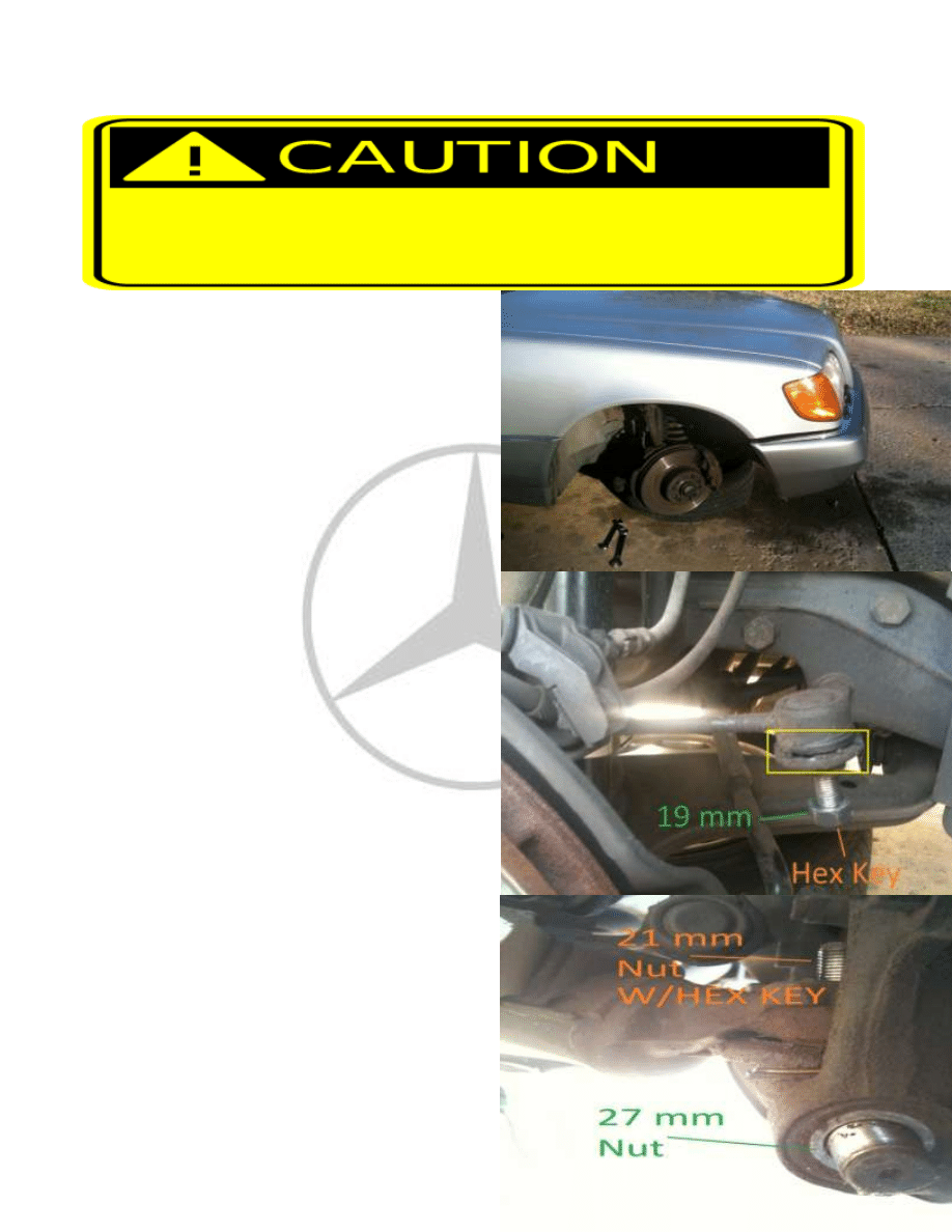
1. Jack up both sides of the car. USE JACK STANDS don’t rely just on the jacks alone even if
it’s a Heavy duty floor jack, you do not want a 2 Tons of fine German metal crushing
you!! Remove tire, and for added safety slide your tires under the engine bay.
2. Put your keys in the ignition unlock the
steering wheel and turn the wheels where
the brake caliper is pointing inwards, you’ll
have better access to the ball joints nut.
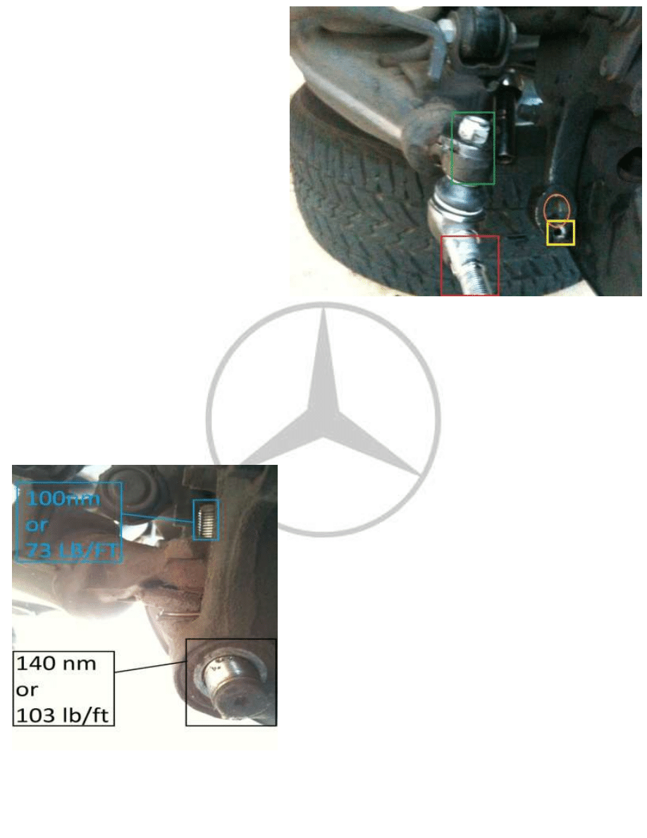
3. Remove the sway bar link using a 19 mm
socket and a Hex Key (forgot size), to
prevent the bolt from turning with the nut
together, removing enables the arm
assembly to manipulate thus makes better
access to ball joint, you’ll see later down
this guide. Also as you can see in the
picture (yellow square) sway bar links are
clearly shot and due for a change
4. Next remove the nut from the ball joint,
you’ll need a 27 mm socket & breaker bar
for the bottom and 21 mm wrench with
Hex key for the top (forgot what size) to
prevent the nut from turning with the bolt
together
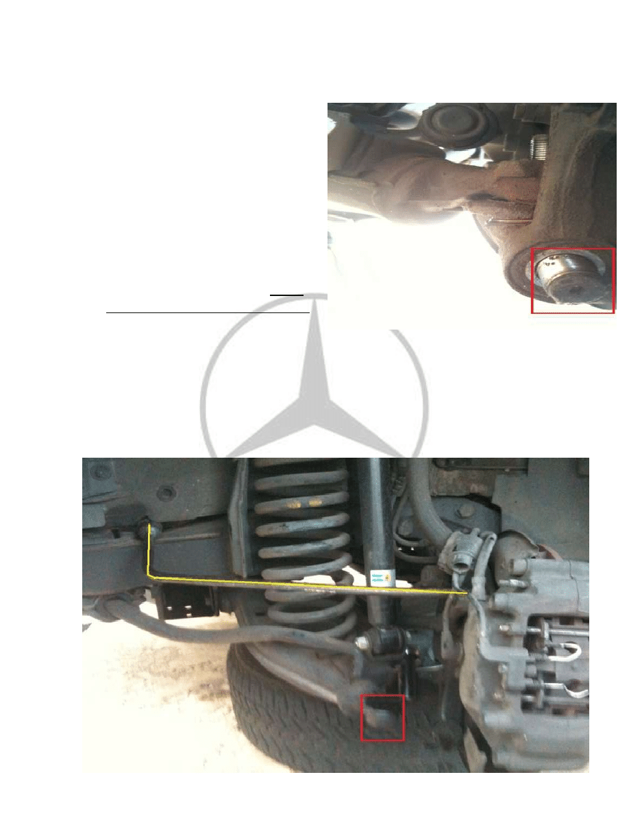
5. Now here comes the tricky part removing
the ball joint from the arm, this is where I
spent most of my time. To make your life
easier start by removing the lower part
first (red square), you may use a ball joint
remover but I find it easier to use a mini
sledge hammer and hit the bottom (red
square) till it pops out, it take quite a few
hits so be prepared for intense hammer
time, be careful not to hit the brakes
caliper, rotor or any other things. Wear
eye and ear protection when doing this!!
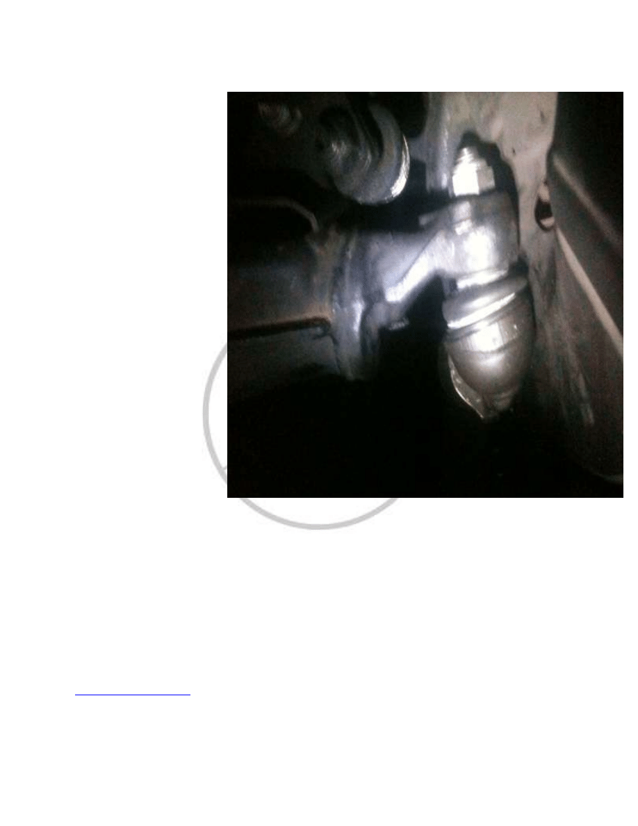
6. Ok now ones you have the bottom part of the ball joint out, turn the steering the
opposite direction and you should be able to hyperextend the brake/rotor assembly
away from the lower control arm like this (see picture below) now tie it up or put
something, like a bar (yellow line) to hold the brake & rotor assembly in its place. Now
you should see the entire ball joint, (red box) and have a clear access to it. Time to use
the Jaws of Life i.e. Ball Joint Separator tool or not…Bilstien SHOCKS FTW!
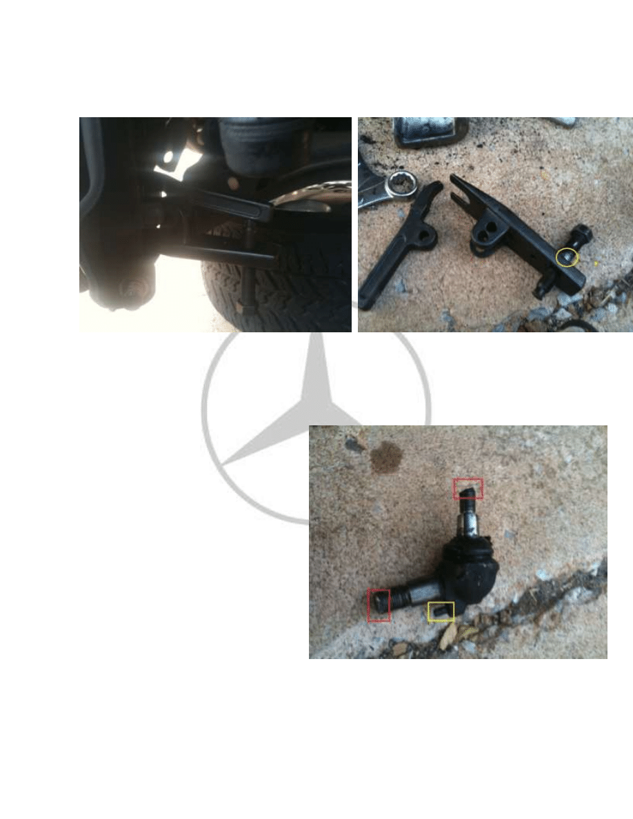
7.
Now that you have a clear access to the upper part of the ball joint you may use a ball
joint separator tool, but it didn’t work for my case, as the universal cheap o joint
separator could not break free of the very tightly fitted ball joint so the tool broke
instead, strip its groove (yellow circle in pic 2) rendering it nothing but just scrap metal,
kind a scary to think how tight these ball joint can get, anyways time for plan B. So plan B
is to use a small scissors jack and jack
up under the lower control arm to
support ( to prevent damage the
upper control arm and shocks) and
use the mini sledge hammer and
pound the heck out of it until it drops,
for me it took a bit of pounding, it
was in there for good! Careful not to
hit the brake assembly, shocks,
springs and the lower control arm and
use eye and ear protection when
doing this or else you’re definitely
going to go deaf and maybe blind too
Above: Red shows the damage done by
hammering on the spindle, and in the yellow
box shows the aligning pin that is important for
installation, will explain later. .
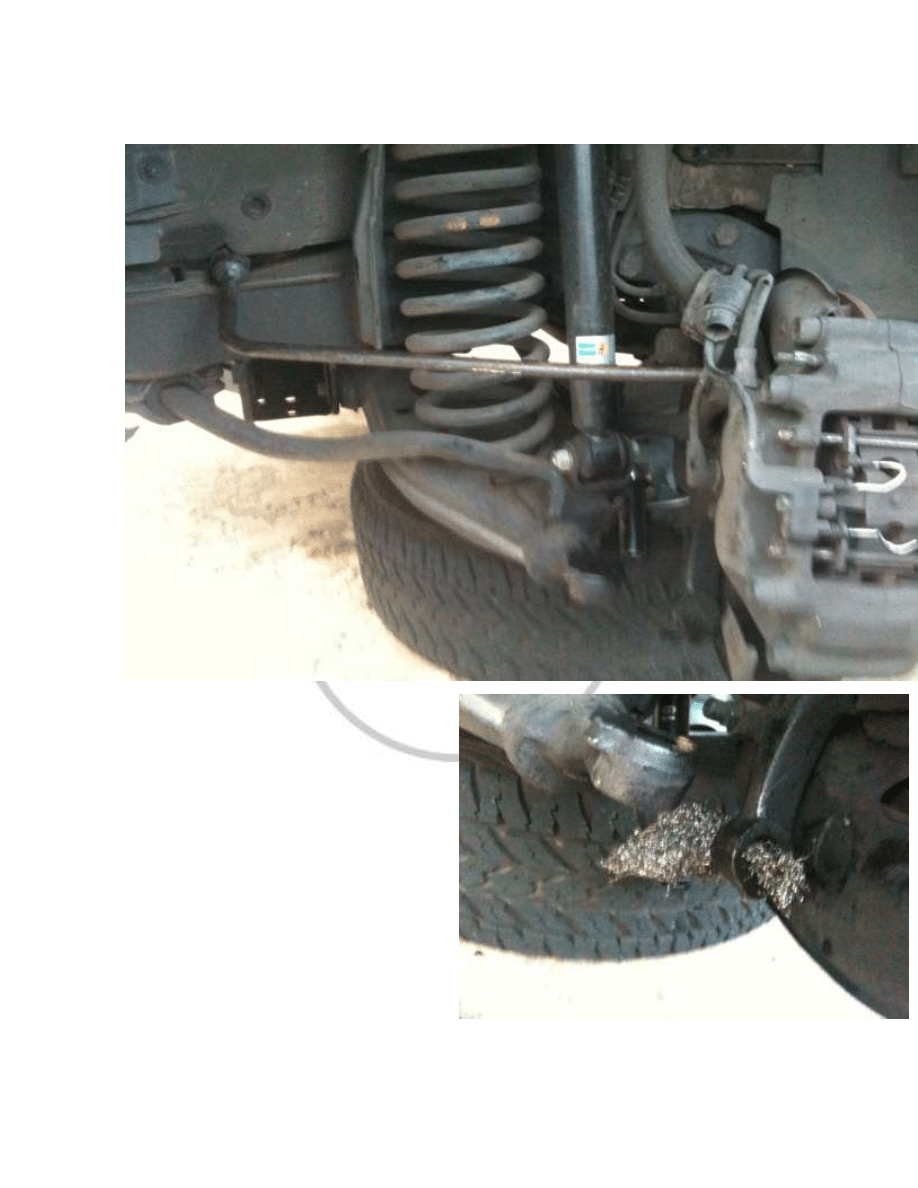
8. Now that with that lower ball joint removed you should have something like this…
Ahh, jointless, yes I know it’s the same
picture I should slap myself for
forgetting to take another pic, now this
would be a good time to clean the
holes of any rust build up, use a nylon
brush or a steel wool and some WD-40
to clean the holes, you may use a metal
brush but just be careful with it. Once
the cleaning is done apply some grease
on the holes and the new ball joint and
you’re ready for installation!!
9. Installation.
Alright we’re almost done.
Remember that picture of a ball
joint in step 7? Do you see that
pin? That is the aligning pin that
fits right into that small hole
(yellow box) below the bigger
hole. It’s important to install that
pin into its socket (yellow box),
or else your ball joint will not
seat properly, damage will occur
to the ball joint, and you’ll have
to buy another one.
Now installing the ball joint is goanna be tricky because it seems that you’re going to
have to align that pin and at the same time bolt them up but, but really you don’t have
to. So this is how I did it, install the ball joint to the lower control arm first (see pic/green
box), grasp the lower ball joint (red box) firmly and move the ball joint around to make it
easier to manipulate later. Then hand tighten the upper ball joint nut (green box), do not
tighten it down as you need to move it around. Then swing the brake assembly and try to
get the lower bolt (red box) on to its place (orange circle) and thread in the nut on to the
lower ball joint (red box), don’t worry about the pin for now you want to get the ball joint
bolts into its holes for now. Now once you have the nut
threaded on to the lower part of the ball joint (red
box),slowly tighten up the upper part of the ball joint
(green box) to raise up the ball joint into its socket until
the pin lines up with the pin hole, now you may need
to use a screw driver or vice grip and leverage the ball
joint pin side to side to align right into the pin hole, you
may pull on the brake & rotor assembly to check if the
pin slides into its place. Ones pin can slide into the
hole, keep pull on the brake & rotor assembly and
tighten the lower part of the ball joint (red box) until
the align pin sits into its hole (yellow box) then tighten
up the upper part of the ball joint (green box) until the
rubber boot begins to compress, Then torque the
upper at 100 nm or 73 lb/ft and then bottom at 140
nm or 103 lb/ft (see pic 2), do not exceed torque
values or premature wear may occur.
And that’s it you’re
done, just be sure that
you remember to
reinstall/replace the
sway bar link, and take it
for a test drive to check
for any noises, if it does
make clunking/or thud
noise it means the ball
joint is not tight enough.
Also make sure you
replace any other wore
out suspension
components like upper
control arm, lower
control bushings, sway
bar link, tie rod, or else
you’ll have a premature
ball join failure!! I hope
this DIY guide has helped
you!
Above: As you can see it’s already night when it was completed. Took
me almost 6 hrs to do both sides with taking pictures, 1/2 of the time
spent was just hammering the ball joint loose! 1/4 Let’s hope it will
last me for another 10 years before doing it again…
If you have any comment questions or corrections that needs to be made email me at
Wyszukiwarka
Podobne podstrony:
Popular Mechanics Ball Joint Replacement
DIY Guide How to research companies
Eaton VP 33 76 Ball Guide Unit Drawing
Eaton FM 33 76 Ball Guide Unit Drawing
Diy Japanese Garden Easy Step By Step Guide To Make
Eaton VM 33 76 Ball Guide Unit Drawing
Eaton VP 33 76 Ball Guide Unit Drawing
eBook DIY Woodworking Plans Guide To Wood Finishing
Eaton VP 33 76 Ball Guide Unit Drawing
Eaton FM 33 76 Ball Guide Unit Drawing
Diy How To Home Guide Wood Joints
Eaton VM 33 76 Ball Guide Unit Drawing
ULTIMATE DIY FACE MASK GUIDE(1)
ULTIMATE DIY FACE MASK GUIDE
Lower Limb Jeopardy
więcej podobnych podstron