
Functional Size Measurement
Methodologies

What is FSM ?
•
Definitions:
• Functional Size: A size of the
software derived by quantifying the
Functional User Requirements.
• Functional Size Measurement
(FSM): The process of measuring
Functional Size.”
ISO #14143-1
Standard defintions

Why we need FSM ?
• “You cannot control what you cannot
measure”
-
Tom DeMarco

Intuitive approach
•
Let's count the...
• Classes of a Software system
• Lines Of Code
• Actors/use-cases

Software Metrics
• Cohesion
• Coupling (Dependency)
• Complexity
• Functional Point Analysis

Cohesion
• A measure of how well the lines of
source code within a module work
together to provide a specific
functionality.

High Cohesion
• Modules of high cohesion are
preferable, as they are associated
with: robustness, reliability, reusability
and understandability.
• High cohesion often correlates with
low coupling

Low Cohesion
• Modules of low cohesion modules are
associated with undesirable traits
such as difficult to maintain, difficult
to test, difficult to reuse, and even
difficult to understand.

Coupling (Dependency)
• The degree to which each program
module relies on each other module.
• Coupling is usually contrasted with
cohesion. Low coupling often
correlates with high cohesion, and
vice versa.

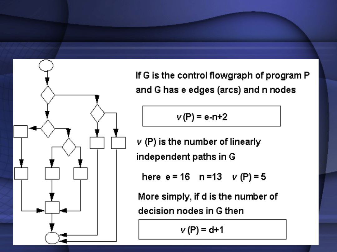
Cyclomatic complexity
• Directly measures the number of
linearly independent paths through a
program's source code.

Cyclomatic complexity
• Complexity is being computed using a
graph that describes the control flow
of the program. The nodes of the
graph correspond to the commands of
a program. A directed edge connects
two nodes, if the second command
might be executed immediately after
the first command.
Cyclomatic complexity

Function Point Analysis
(FPA)
• A method used to gauge the size and
complexity of computer software,
employing a function point as a unit
of measure.
• Function points are a unit measure
for software size, much like an hour is
to measuring time

FPA in Practice
• Function points measure software by
quantifying functionality provided
to the user
• A method that to break systems into
smaller components, so they can be
better understood and analyzed.

Why we need FSM ?
• Increasingly growing software
size and complicity
• Ever-expanding user requirements
• Estimating

Estimating with FSM
• Cost effectivness:
• Size of Software System / Project Cost
• Quality:
• Errors reported / Size of Software System
• etc.

FSM in Practice
• Measure project or organisational
performance
• Estimate the resources - duration and
cost of projects

FSM Methodologies
• IFPUG Function Point Analysis
• Mark II Function Point Analysis
• COSMIC-FFP
(ISO #14143-1
standard covers all these methods)

What is an FSM methodology
• Principles and philosophy
• Characteristics
• Steps for measuring software
• Applicability

What is an FSM methodology
• Principles and philosophy
• Characteristics
• Steps for measuring software
• Applicability

Mk II FPA
Description
Cases
Tu zacznij....

Applicability of Mk II FPA
MkII FPA is a method that assists in measuring
process efficiency and managing costs for
application software development, change or
maintenance activities.
It measures a software product size independent
of technical characteristics of the software, in
terms relevant to users. It can be:
· applied early in the software development
process
· applied uniformly throughout the software's
lifetime
· interpreted in business terms, and
· understood by users of the software.

Either directly, or coupled with effort, defect
counts and other measures, MkII FPA can be
used for a variety of purposes, including to:
• measure project or organisational
performance (productivity, delivery rate and
quality).
• compare internal and external IT performance
• compare application quality and reliability
• compare normalised development,
maintenance and support costs of
applications on different platforms
• · estimate the resourcing requirements,
duration and cost of projects
• · contribute to the cost and risk elements of
the business case for a new project

• assist in identifying all requirements
before an application has been developed
• control ‘creeping elegance’ or scope
change during projects
• assign work to team members
• determine the size of the application
asset base
• produce useful, high-level, functional
documentation of old ‘legacy’ systems
that lack up-to-date functional
documentation
• determine the replacement value of
applications.

The Mk II Function Point
Analysis Rules

Rule 1 Boundary
• Mk II FPA is used to measure the size of
the functionality required by the users
of an application, within a boundary
defined for the purpose of the FP count.
• The application or part of the
application enclosed by the boundary
must be a coherent body of
functionality, comprising one or more
complete Logical Transaction Types. (In
the following, ‘Type’ is dropped for ease
of reading.)

Rule 2 Functional Size and
Logical Transactions
• The Functional Size of an application
is the sum of the sizes of each of the
Logical Transactions whose input and
output components cross the
enclosing boundary.
• A Logical Transaction is counted once
when sizing an application, even
though it may be executed from more
than one point in the application.

Processing Component of
Logical Transactions
• Mk II FPA is used to measure the size of
the functionality required by the users
of an application, within a boundary
defined for the purpose of the FP count.
• The application or part of the
application enclosed by the boundary
must be a coherent body of
functionality, comprising one or more
complete Logical Transaction Types. (In
the following, ‘Type’ is dropped for ease
of reading.)

Rule 3 Processing Component
of Logical
• The processing component of a
Logical Transaction is analysed by
reference to its manipulation (i.e.
create, update, delete, or read) of
stored data.

Rule 4 Input and Output
Components of Logical
Transactions
• The input and output components of a
Logical Transaction are sized by
counting the number of Data Element
Types crossing the application
boundary, via each component
respectively.

Rule 5 Logical Transaction
Size
• The Functional Size of a Logical
Transaction is the weighted sum of
the input, processing, and output
components of the Logical
Transaction.
• The industry standard weights are as
follows: Input Weight is 0.58 (per
Input Data Element Type), Processing
Weight is 1.66 (per Entity Type
Reference), and the Output Weight is
0.26 (per Output Data Element Type).

Measurement Steps
Mk II FPA
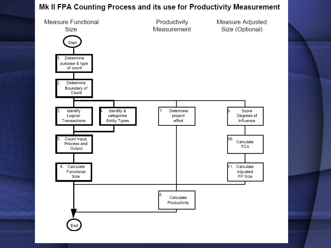

Step 1 Determine the Viewpoint, Purpose
and Type of the Count
Identify the customer for the count, and the
purpose. For example, is it to measure the
work-output of a particular group of
developers, or the functionality ‘owned’ by a
particular user? Is the aim to count all of the
functionality which was required, or the
functionality which was delivered to the
user?
Questions which may help determine what has
to be counted include:
• Does the project involves development,
change, maintenance, or support?
• When did/does the project begin and end?

Step 2 Define the
Boundary of the Count
• This is also linked with Step 1.
Drawing the boundary determines the
Logical Transactions to be included in
the count, and identifies any
interfaces.

Step 3 Identify the Logical
Transactions
• Logical transactions are the lowest
level processes supported by the
application, consistent with Rule 2

Step 4 Identify and
Categorise the Data Entity
Types
• It is usually highly desirable to have
an entity-relationship data model for
the requirements, to identify all the
Data Entity Types. However, as only
the Primary Entity Types are needed,
a full Third Normal Form analysis is
not needed.

Step 5 Count the Input Data
Element Types, the Data Entity
Types Referenced, and the
Output Data Element Types.
• For each Logical Transaction, count
the number of Input Data Element
Types (Ni), the number of Data Entity
Types Referenced (Ne), and the
number of Output Data Element Types
(No).

Step 6 Calculate the
Functional Size
The Functional Size (Function Point Index) is the
weighted sum over all Logical Transactions, of the
Input Data Element Types (Ni), the Data Entity Types
Referenced (Ne), and the Output Data Element Types
(No). So the Function Point Index (FPI) for an
application is:
• FPI = Wi * SNi + We * SNe + Wo * SNo,
where ‘S‘ means the sum over all Logical Transactions,
and the industry average weights per Input Data
Element Type, Data Entity Type Reference and Output
Data Element Type are, respectively:
• Wi = 0.58
• We = 1.66
• Wo = 0.26

Step 7 Determine Project
Effort
Determine the total effort and elapsed
time for the project.

Step 8 Calculate Productivity and
other PerformanceParameters
Examples:
• Productivity = FPI / Project Effort,
• Delivery Rate = FPI / Elapsed Time

Step 9 Score the Degrees
of Influence
Optionally assess the Degrees of
Influence of each of the Technical
Complexity Adjustment
characteristics.

Step 10 Calculate the Technical
Complexity Adjustment
• Optionally calculate the TCA.

Step 11 Calculate Adjusted FP
Size and Performance Parameters
• Optionally use the TCA calculated in
Step 10 to calculate the Adjusted FP
Size which can then replace the FPI to
derive the associated performance
parameters (e.g. productivity and
delivery rate), as in Step 8.

IFPUG Function Point Analysis

•The IFPUG 4.0 method of
sizing software is based on a
model of analysing the
software requirements or user
functionality into five types of
components, namely (next
slide):

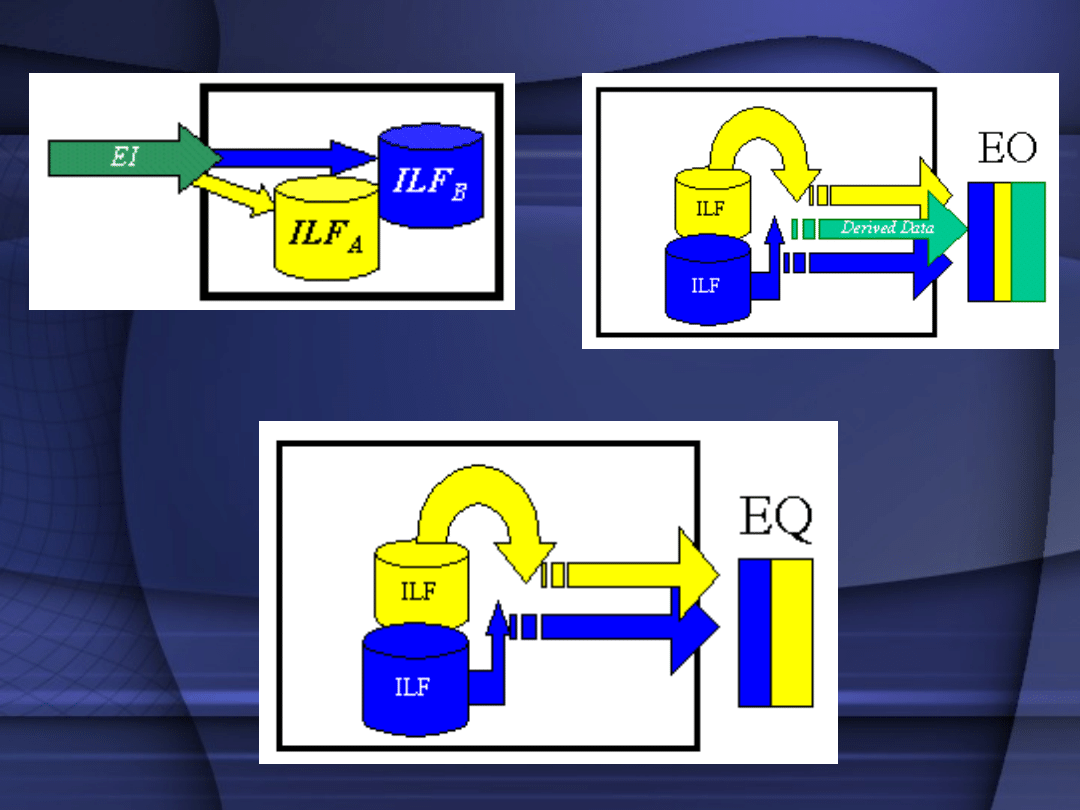
• External Inputs (EIs - an elementary process on
input or control data that comes from outside
the system boundary)
• External Outputs (EOs - an elementary process
that generates data or control information sent
outside the system boundary)
• External Inquiries (EQs - an elementary process
made up of an input/output combination that
results in data retrieval, but which does not
maintain any internal logical files nor derive any
data for output)
• Internal Logical Files (ILFs - files whose contents
are created and/or updated and/or deleted by
External Inputs)
• External Interface Files (EIFs - files whose
contents are created, updated and deleted by
other distinct software, but which are only read
by the software being sized)
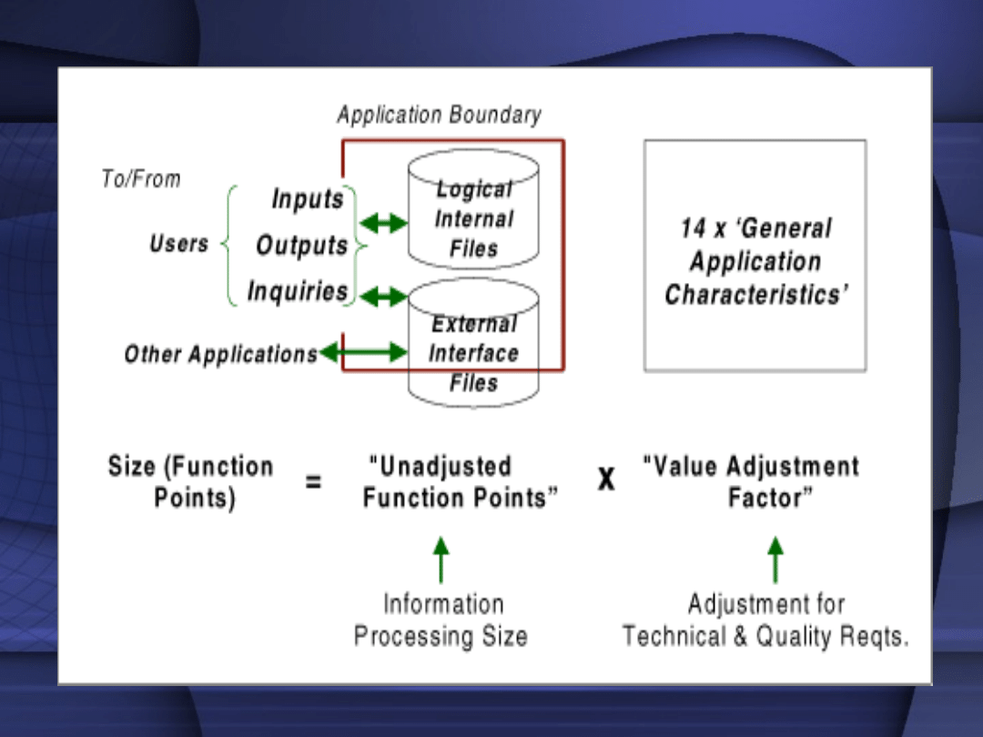

•The five types of components are
classified as 'simple', 'average' or
'complex' depending on the number
of Data Element Types (DETs) on the
component and other attributes,
and are awarded Unadjusted
Function Points accordingly.
•For example a simple EI gets 3 FP,
an average EI 4 FP and a complex
EI 6 FP. The UFP size of an item of
software is the sum of the UFP sizes
of all its components of each of the
five types.

General System Characteristic Brief
Description
• 1.Data communications -How many
communication facilities are there to aid in the
transfer or exchange of information with the
application or system?
• 2.Distributed data processing - How are distributed
data and processing functions handled?
• 3.PerformanceWas response time or throughput
required by the user?
• 4.Heavily used configuration - How heavily used is
the current hardware platform where the
application will be executed?
• 5.Transaction rate - How frequently are
transactions executed daily, weekly, monthly, etc.?
• 6.On-Line data entry - What percentage of the
information is entered On-Line?

• 7.End-user efficiency - Was the application
designed for end-user efficiency?
• 8.On-Line update - How many ILF’s are updated by
On-Line transaction?
• 9.Complex processing - Does the application have
extensive logical or mathematical processing?
• 10.Reusability - Was the application developed to
meet one or many user’s needs?
• 11.Installation ease - How difficult is conversion
and installation?
• 12.Operational ease - How effective and/or
automated are start-up, back-up, and recovery
procedures?
• 13.Multiple sites - Was the application specifically
designed, developed, and supported to be installed
at multiple sites for multiple organizations?
• 14.Facilitate change - Was the application
specifically designed, developed, and supported to
facilitate change?

COSMIC-FPP

COSMIC-FPP – Advantages (1/2)
• Applicable early in the software
lifecycle
• Independent of software development
methods and technology
• Based on objective criteria
• Universal
• Covers very different software
domains

COSMIC-FPP – Advantages (2/2)
• Flexible
• Lacks correlation fator
• Respects tier and layer based
architecture
• Applicable for embedded and
distributed system designs
• Uses only the FURs (Functional User
Requirements)

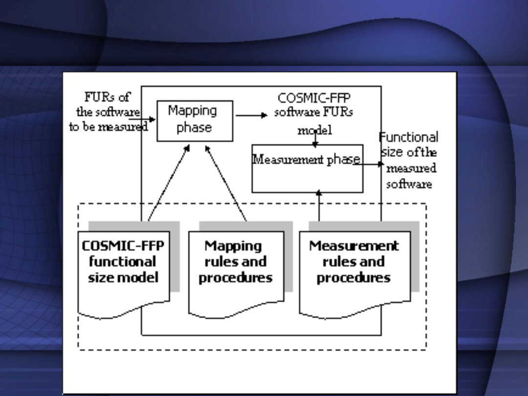
COSMIC-FFP Phases
•
The COSMIC-FFP process is based on
two phases:
• The Mapping Phase in which a
COSMIC-FFP model of the FURs
suitable for the measurement phase is
generated.
• The Measurement Phase, where
the measurement rules are applied to
this FUR model to derive size on the
basis of the ISO standard for COSMIC-
FFP.
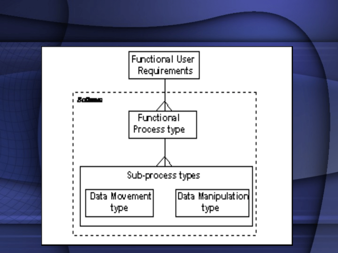
COSMIC-FPP

COSMIC-FPP - Measurement
• FURs can be decomposed into a set of
functional processes
• Each functional process is a unique
set of sub-processes performing either
a data movement or a data
manipulation
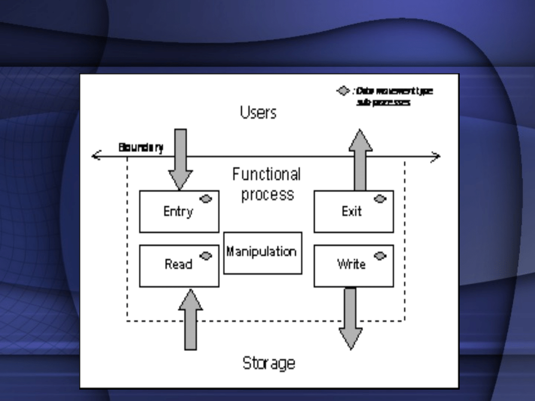
COSMIC-FPP

COSMIC-FPP Data movements
• Four types of data movements:
•
Entry, Exit
movements - data from/to
the user across the boundary of the
functional process.
•
Read, Write
movements - move data
from and to persistent storage.
COSMIC-FPP

COSMIC-FPP Measurements
• Each data movement is assigned a
single unit of measure of 1 = 1 Cfsu
(by convention)
• The total size of the software =
addition of all data movements.
• Cfsu - Cosmic functional size unit.

COSMIC-FPP to Use cases
• Use cases can also serve as
inputs for COSMIC-FPP
Document Outline
- Slide 1
- Slide 2
- Slide 3
- Slide 4
- Slide 5
- Slide 6
- Slide 7
- Slide 8
- Slide 9
- Slide 10
- Slide 11
- Slide 12
- Slide 13
- Slide 14
- Slide 15
- Slide 16
- Slide 17
- Slide 18
- Slide 19
- Slide 20
- Slide 21
- Slide 22
- Slide 23
- Slide 24
- Slide 25
- Slide 26
- Slide 27
- Slide 28
- Slide 29
- Slide 30
- Slide 31
- Slide 32
- Slide 33
- Slide 34
- Slide 35
- Slide 36
- Slide 37
- Slide 38
- Slide 39
- Slide 40
- Slide 41
- Slide 42
- Slide 43
- Slide 44
- Slide 45
- Slide 46
- Slide 47
- Slide 48
- Slide 49
- Slide 50
- Slide 51
- Slide 52
- Slide 53
- Slide 54
- Slide 55
- Slide 56
- Slide 57
- Slide 58
- Slide 59
- Slide 60
- Slide 61
- Slide 62
- Slide 63
Wyszukiwarka
Podobne podstrony:
BYT 2005 Pomiar funkcjonalnosci oprogramowania
BYT 2005 Software testing
BYT 2005 Role w zespole projektowym
BYT 2005 Microsoft Office Project 2003 Professional
BYT 2005 Komunikacja
BYT 2005 Project management
BYT 2005 Cykl zyciowy oprogramowania
BYT 2005 Testowanie oprogramowania
BYT 2005 Komunikacja w zespole projektowym
BYT 2005 Pomiar funkcjonalnosci oprogramowania
[Friedrich Schneider] Size and Measurement of the Informal Economy in 110 Countries Around the Worl
AM1 2005 W1upg
Wytyczne ERC 2 2005
Wyklad3 2005
BYT 109 D faza projektowania
więcej podobnych podstron