2004 Microchip Technology Inc.
DS91085A-page 1
TB085
INTRODUCTION
The recent interest in intelligent power supplies has
driven the development of a new class of microcontrol-
ler friendly PWM generators. These PWM generators
are the mixed signal control blocks for Switch mode
power supplies. One such device is the MCP1630. The
MCP1630 contains the 3 main elements for designing
a switching power supply as a peripheral to a microcon-
troller: a set/reset flip-flop, a high-speed voltage
comparator and an op amp to implement the error
amplifier (see Figure 1).
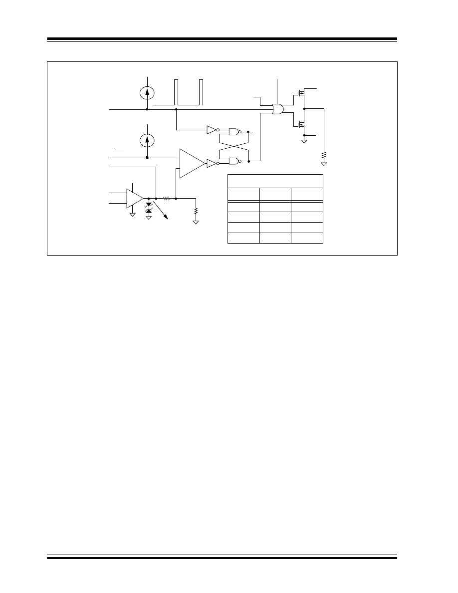
The microcontroller controls the MCP1630 through its
clock input. The frequency of the clock determines the
pulse frequency of the PWM output, and the duty cycle
of the clock limits the maximum PWM duty cycle of the
output. Control of the duty cycle between 0 and the
maximum set by the clock input is determined by the
current feedback to the comparator and the output of
the error amplifier (see Figure 2).
Because the MCP1630 does not contain an on-chip
oscillator, its application in non-intelligent or dumb
power supply designs, is limited. However, marrying
the MCP1630 with a small pin-count microcontroller
solves the oscillator problem and opens up possibilities
for other features such as:
• Variable pulse frequency soft-start
• External shutdown control
• Under-voltage lockout
• Over temperature shutdown
THEORY OF OPERATION
This technical brief will examine a design which
combines the PIC10F206, a 6-pin SOT-23 microcon-
troller, with the MCP1630. The power supply design
presented is a full proportional-feedback continuous
inductor current, current-mode, boost power supply
generating 15V out at .25 amps from a 9 V
DC
input. The
PIC10F206 generates the clock for the MCP1630 and
through that control, implements the previous list of
features.
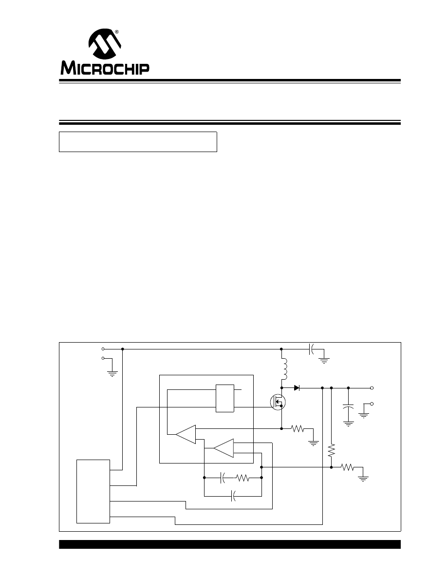
FIGURE 1:
TYPICAL SWITCH MODE POWER SUPPLY BLOCK DIAGRAM
Author:
Keith Curtis
Microchip Technology Inc.
MCP1630
Q
Q
R
S
Clock
Input
+
–
+
–
Comparator
Op Amp
Reference
Microcontroller
Flip-Flop
Voutput
Vsupply
A Simple Circuit for Driving Microcontroller
Friendly PWM Generators
TB085
DS91085A-page 2
2004 Microchip Technology Inc.
FIGURE 2:
MCP1630 HIGH-SPEED PWM
HARDWARE
The PIC10F206 is well suited for this function. It has an
on-chip voltage comparator for the under-voltage
detect and it has sufficient I/O to control the MCP1630
and monitor the external inputs.
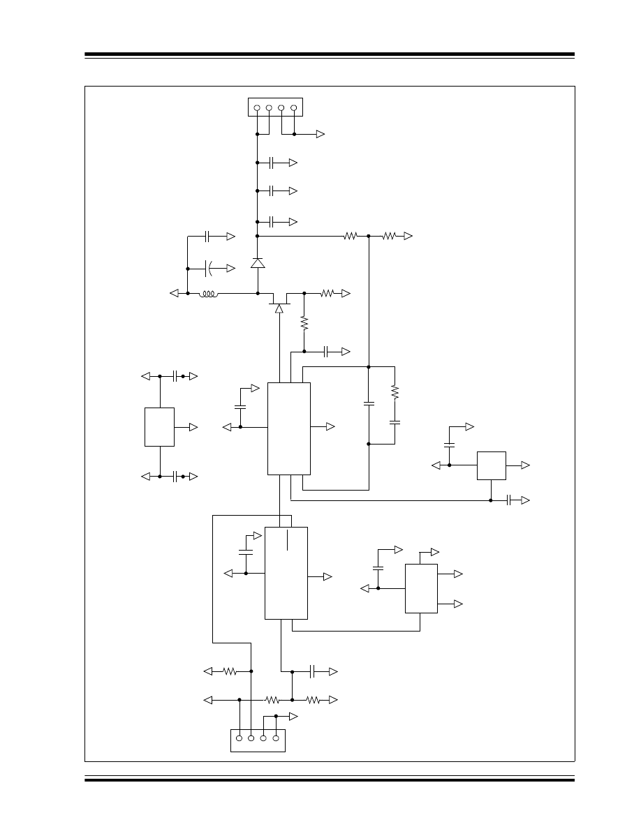
The microcontroller monitors the inputs and generates
the 250 kHz clock, all in software. Because the controls
are simple, the control circuit only needs the microcon-
troller and a few components to implement all the con-
trol functions. Figure 3 shows the resulting schematic.
Microcontroller inputs are connected to a divided sup-
ply voltage, a digital temperature sensor and the shut-
down input. The remaining output is the output driving
the MCP1630 clock input.
For under-voltage detection, the divided supply voltage
is routed to the non-inverting input of the comparator.
The inverting input is tied internally to the on-chip 0.6V
reference. The software then monitors the comparator
output to detect an under-voltage condition.
The temperature sensor is implemented using a digital
output device that pulls its output low when the thresh-
old temperature is exceeded. The software monitors
the input to detect an over-temperature condition and
shuts down the pulse output if the temperature goes to
high. When the temperature falls back below the
threshold temperature, the sensor output returns high
and the software soft-starts the pulse output. Hystere-
sis built in the temperature sensor prevents chattering
and the sensor’s trip temperature is preset when the
sensor is manufactured.
The shutdown input, GP1, is tied to whatever remote
start-up logic is desired. The software polls the input to
determine if a shutdown is requested and terminates
the pulse output if the input is low. Raising the input
restarts the supply.
V
IN
OSC IN
0.1
µ
A
UVLO
Overtemperature
G
ND
100 k
Ω
V
EXT
V
IN
Q
Comp
+
-
EA
-
+
FB
V
REF
V
IN
2.7V Clamp
2R
R
R
Q
S
V
IN
CS
COMP
Latch Truth Table
S
R
Q
0
0
Qn
0
1
1
1
0
0
1
1
1
2004 Microchip Technology Inc.
DS91085A-page 3
TB085
FIGURE 3:
SWITCH MODE POWER SUPPLY SCHEMATIC
1
2
3
4
Inp
u
t
J1
+9
V
+
5
V
R1
10
K
R2
8.2
K
R3
1K
C2
100
0
p
F
GP
0/C+
GP
1/C-
G
P
2/T
0
CK
I/CO
GP
3/M
C
LR
V
DD
V
SS
1
3
4
6
2
U1
P
IC
1
0F
20
6
+5
V
5
C1
0.1
µ
F
V
DD
T
o
v
r
Hyst
4
5
3
G
ND
G
ND
12
+5
V
C
3
10
0
p
F
U4
T
C
65
01
OS
C
V
RE
F
COM
P
4
8
1
DR
VR
CF
B
VF
B
V
DD
V
SS
6
3
2
5
C1
0
C1
1
R1
0
10
0K
V
IN
V
OU
T
V
SS
2
C9
1
µ
F
3
1
+5
V
C
8
0.
1
µ
F
U3
MC
P
1
52
5
R9 10
0
1
C1
2
15
00
pF
R8
0.
56
3
Q1
IR
LM
L25
02
2
1
2
3
4
15
V
DC
J2
C1
6
100
0
p
F
C1
5
C1
4
1.
0
µ
F
D1
B2
3
0
R6
2.4
K
R7
L1
+C1
7
C1
3
+9
V
7
+5
V
C7 0.
1
µ
F
U2
MC
P
1
6
3
0
LM
348
0-5
Out
In
Co
m
3
+9
V
+
5
V
C5
0.
1
µ
F
C6
0.1
µ
F
U5
220
µ
F
.1
µ
F
1
µ
F
22
µ
F
51
0
Ω
1.0
µ
F
.0
33
µ
F
Ou
tp
ut
2004 Microchip Technology Inc.
DS91085A-page 4
TB085
SOFTWARE
The software monitors the inputs and generates the
output pulse using a simple bit-set/bit-clear loop,
expanded to interleave all the input testing. By keeping
the bit-set to bit-set time to 4 cycles, the output duty
cycle is locked to 25% for a 250 kHz clock. The latency
time for a shutdown is 16 cycles. Figure 4 shows the
code listing.
FIGURE 4:
CODE LISTING 1
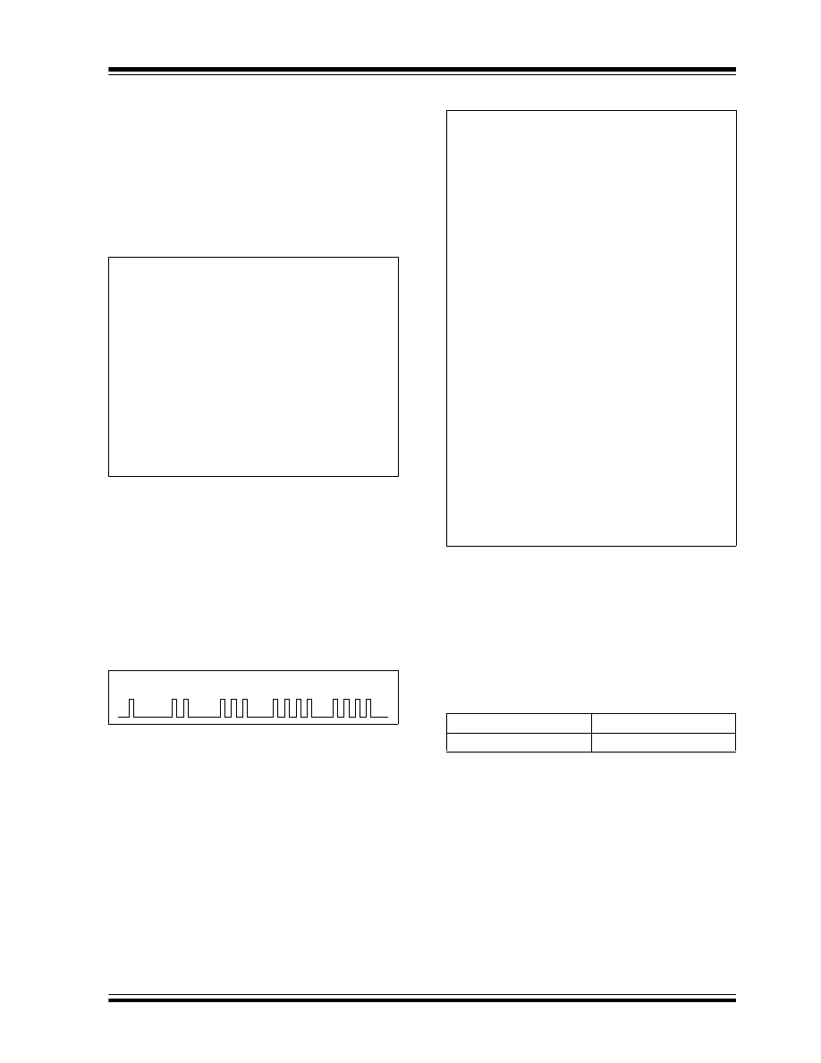
The soft-start function is generated by ramping up the
number of output pulses. At start-up, a single pulse is
followed by a long delay. Next, 2 pulses are followed by
a shorter delay, then 3, 4 and so on until the pulse chain
is continuous.
The soft-start code is implemented as a table of bit-set/
bit-clear/delay instructions, similar to code listing 1 with
a delay and control section. Figure 5 shows the timing
of soft-start and Figure 6 is an excerpt from the actual
code.
FIGURE 5:
PWM CLOCK
FIGURE 6:
CODE LISTING 2
CONCLUSION
Using a combination of software and simple hardware,
an efficient control for a PWM generator is imple-
mented with many of the features found in more com-
plex controllers. The result is a modular building-block
style design with many advanced features that can be
easily customized for a customer’s needs.
TABLE 1:
MEMORY USAGE
loop
BSF
PWM
BCF
PWM
;generate a pulse
BTFSS
CMPOUT
;test 4 low Vin
GOTO
Low_volt
;if low shutdown
BSF
PWM
BCF
PWM
;generate a pulse
BTFSS
GP1
;test 4 hi temp
GOTO
High_temmp ;if hi shutdown
BSF
PWM
BCF
PWM
;generate a pulse
BTFSS
GP3
;test 4 shutdown
GOTO
shtdwn
;if shutdown
BSF
PWM
BCF
PWM
;generate a pulse
GOTO
loop
;infinate loop
PWM Clock
GPR
3 bytes
Program
153 words
Soft_Start
MOVLW
.32
;table of 32
MOVWF
counter
MOVLW
Last-Table
;set to last
MOVWF
pointer
Loop
MOVF
counter,w
;reload delay
MOVWF
count
Delay
;generate delay
NOP
DECFSZ
count,f
;decrement count
GOTO
Delay
;repeat til done
MOVF
pointer,w
;get pntr 4 jump
ADDWF
PCL,f
;jump
Table
BSF
PWM
BCF
PWM
;32 pulse
GOTO
$+1
;2 cycle delay
|-----------;29 copies of pulse + delay
BSF
PWM
BCF
PWM
;2nd pulse
GOTO
$+1
Last
BSF
PWM
BCF
PWM
GOTO
$+1
DECF
pointer,f
;add a pulse
DECF
pointer,f
DECF
pointer,f
DECFSZ
counter,f
;decrease delay
GOTO
Loop
;if 10, continue
loop_forever
;if 0, goto main
2004 Microchip Technology Inc.
DS91085A-page 5
Information contained in this publication regarding device
applications and the like is provided only for your convenience
and may be superseded by updates. It is your responsibility to
ensure that your application meets with your specifications.
MICROCHIP MAKES NO REPRESENTATIONS OR WAR-
RANTIES OF ANY KIND WHETHER EXPRESS OR IMPLIED,
WRITTEN OR ORAL, STATUTORY OR OTHERWISE,
RELATED TO THE INFORMATION, INCLUDING BUT NOT
LIMITED TO ITS CONDITION, QUALITY, PERFORMANCE,
MERCHANTABILITY OR FITNESS FOR PURPOSE.
Microchip disclaims all liability arising from this information and
its use. Use of Microchip’s products as critical components in
life support systems is not authorized except with express
written approval by Microchip. No licenses are conveyed,
implicitly or otherwise, under any Microchip intellectual property
rights.
Trademarks
The Microchip name and logo, the Microchip logo, Accuron,
dsPIC, K
EE
L
OQ
, micro
ID
, MPLAB, PIC, PICmicro, PICSTART,
PRO MATE, PowerSmart, rfPIC, and SmartShunt are
registered trademarks of Microchip Technology Incorporated
in the U.S.A. and other countries.
AmpLab, FilterLab, Migratable Memory, MXDEV, MXLAB,
PICMASTER, SEEVAL, SmartSensor and The Embedded
Control Solutions Company are registered trademarks of
Microchip Technology Incorporated in the U.S.A.
Analog-for-the-Digital Age, Application Maestro, dsPICDEM,
dsPICDEM.net, dsPICworks, ECAN, ECONOMONITOR,
FanSense, FlexROM, fuzzyLAB, In-Circuit Serial
Programming, ICSP, ICEPIC, MPASM, MPLIB, MPLINK,
MPSIM, PICkit, PICDEM, PICDEM.net, PICLAB, PICtail,
PowerCal, PowerInfo, PowerMate, PowerTool, rfLAB,
rfPICDEM, Select Mode, Smart Serial, SmartTel and Total
Endurance are trademarks of Microchip Technology
Incorporated in the U.S.A. and other countries.
SQTP is a service mark of Microchip Technology Incorporated
in the U.S.A.
All other trademarks mentioned herein are property of their
respective companies.
© 2004, Microchip Technology Incorporated, Printed in the
U.S.A., All Rights Reserved.
Printed on recycled paper.
Note the following details of the code protection feature on Microchip devices:
•
Microchip products meet the specification contained in their particular Microchip Data Sheet.
•
Microchip believes that its family of products is one of the most secure families of its kind on the market today, when used in the
intended manner and under normal conditions.
•
There are dishonest and possibly illegal methods used to breach the code protection feature. All of these methods, to our
knowledge, require using the Microchip products in a manner outside the operating specifications contained in Microchip’s Data
Sheets. Most likely, the person doing so is engaged in theft of intellectual property.
•
Microchip is willing to work with the customer who is concerned about the integrity of their code.
•
Neither Microchip nor any other semiconductor manufacturer can guarantee the security of their code. Code protection does not
mean that we are guaranteeing the product as “unbreakable.”
Code protection is constantly evolving. We at Microchip are committed to continuously improving the code protection features of our
products. Attempts to break Microchip’s code protection feature may be a violation of the Digital Millennium Copyright Act. If such acts
allow unauthorized access to your software or other copyrighted work, you may have a right to sue for relief under that Act.
Microchip received ISO/TS-16949:2002 quality system certification for
its worldwide headquarters, design and wafer fabrication facilities in
Chandler and Tempe, Arizona and Mountain View, California in
October 2003. The Company’s quality system processes and
procedures are for its PICmicro
®
8-bit MCUs, K
EE
L
OQ
®
code hopping
devices, Serial EEPROMs, microperipherals, nonvolatile memory and
analog products. In addition, Microchip’s quality system for the design
and manufacture of development systems is ISO 9001:2000 certified.

DS91085A-page 6
2004 Microchip Technology Inc.
AMERICAS
Corporate Office
2355 West Chandler Blvd.
Chandler, AZ 85224-6199
Tel: 480-792-7200
Fax: 480-792-7277
Technical Support:
http://support.microchip.com
Web Address:
www.microchip.com
Atlanta
Alpharetta, GA
Tel: 770-640-0034
Fax: 770-640-0307
Boston
Westford, MA
Tel: 978-692-3848
Fax: 978-692-3821
Chicago
Itasca, IL
Tel: 630-285-0071
Fax: 630-285-0075
Dallas
Addison, TX
Tel: 972-818-7423
Fax: 972-818-2924
Detroit
Farmington Hills, MI
Tel: 248-538-2250
Fax: 248-538-2260
Kokomo
Kokomo, IN
Tel: 765-864-8360
Fax: 765-864-8387
Los Angeles
Mission Viejo, CA
Tel: 949-462-9523
Fax: 949-462-9608
San Jose
Mountain View, CA
Tel: 650-215-1444
Fax: 650-961-0286
Toronto
Mississauga, Ontario,
Canada
Tel: 905-673-0699
Fax: 905-673-6509
ASIA/PACIFIC
Australia - Sydney
Tel: 61-2-9868-6733
Fax: 61-2-9868-6755
China - Beijing
Tel: 86-10-8528-2100
Fax: 86-10-8528-2104
China - Chengdu
Tel: 86-28-8676-6200
Fax: 86-28-8676-6599
China - Fuzhou
Tel: 86-591-8750-3506
Fax: 86-591-8750-3521
China - Hong Kong SAR
Tel: 852-2401-1200
Fax: 852-2401-3431
China - Shanghai
Tel: 86-21-5407-5533
Fax: 86-21-5407-5066
China - Shenyang
Tel: 86-24-2334-2829
Fax: 86-24-2334-2393
China - Shenzhen
Tel: 86-755-8203-2660
Fax: 86-755-8203-1760
China - Shunde
Tel: 86-757-2839-5507
Fax: 86-757-2839-5571
China - Qingdao
Tel: 86-532-502-7355
Fax: 86-532-502-7205
ASIA/PACIFIC
India - Bangalore
Tel: 91-80-2229-0061
Fax: 91-80-2229-0062
India - New Delhi
Tel: 91-11-5160-8631
Fax: 91-11-5160-8632
Japan - Kanagawa
Tel: 81-45-471- 6166
Fax: 81-45-471-6122
Korea - Seoul
Tel: 82-2-554-7200
Fax: 82-2-558-5932 or
82-2-558-5934
Singapore
Tel: 65-6334-8870
Fax: 65-6334-8850
Taiwan - Kaohsiung
Tel: 886-7-536-4818
Fax: 886-7-536-4803
Taiwan - Taipei
Tel: 886-2-2500-6610
Fax: 886-2-2508-0102
Taiwan - Hsinchu
Tel: 886-3-572-9526
Fax: 886-3-572-6459
EUROPE
Austria - Weis
Tel: 43-7242-2244-399
Fax: 43-7242-2244-393
Denmark - Ballerup
Tel: 45-4450-2828
Fax: 45-4485-2829
France - Massy
Tel: 33-1-69-53-63-20
Fax: 33-1-69-30-90-79
Germany - Ismaning
Tel: 49-89-627-144-0
Fax: 49-89-627-144-44
Italy - Milan
Tel: 39-0331-742611
Fax: 39-0331-466781
Netherlands - Drunen
Tel: 31-416-690399
Fax: 31-416-690340
England - Berkshire
Tel: 44-118-921-5869
Fax: 44-118-921-5820
W
ORLDWIDE
S
ALES
AND
S
ERVICE
10/20/04
Document Outline
- Introduction
- Theory of Operation
- FIGURE 1: Typical Switch Mode Power Supply Block Diagram
- FIGURE 2: MCP1630 High-Speed PWM
- Hardware
- FIGURE 3: Switch Mode Power Supply Schematic
- Software
- FIGURE 4: Code Listing 1
- FIGURE 5: PWM Clock
- FIGURE 6: Code Listing 2
- Conclusion
- TABLE 1: Memory Usage
- Trademarks
- Worldwide Sales
Wyszukiwarka
Podobne podstrony:
Dynamic gadolinium enhanced subtraction MR imaging – a simple technique for the early diagnosis of L
Avr Dtmf Pwm Generator
An Igbt Inverter For Interfacing Small Scale Wind Generators To Single Phase Distributed Power Gener
HHO PWM Generator
Simple Method for Measuring Recognition Acuity
Atmel Avr USB Software Library for AT90USBxxx Microcontrollers doc7675
więcej podobnych podstron