
1F – 280 ENGINE CONTROLS
DAEWOO M-150 BL2
SYMPTOM DIAGNOSIS
IMPORTANT PRELIMINARY CHECKS
Important: Several symptom procedures call for a care-
ful visual/physical inspection. Always perform the visual/
physical test first. Visual inspections may lead to
correcting a problem without further checks and can
save valuable time.
Step
Action
Value(s)
Yes
No
1
Perform the On-Board Diagnostic (EOBD) System
Check.
Are any Diagnostic Trouble Code(s) (DTCs) stored
in the Engine Control Module (ECM) memory?
–
Go to
Appropriate
DTC Table
Go to Step 2
2
1. Inspect all of the ECM ground connections.
2. Inspect all of the vacuum hoses for splits, kinks,
and proper connections.
3. Check for air leaks at all of the mounting areas of
the intake manifold sealing surfaces.
4. Inspect the ignition wires for cracking, hardness,
proper routing, and carbon tracking.
5. Inspect the wiring for proper connections,
pinches, and cuts.
Are all checks complete?
–
Go to
Appropriate
Symptom Table
–

ENGINE CONTROLS 1F – 281
DAEWOO M-150 BL2
INTERMITTENT
Definition: The problem may or may not illuminate the
Malfunction Indicator Lamp (MIL) or store a Diagnostic
Trouble Code (DTC).
Important: Do not use the Diagnostic Trouble Code
(DTC) tables for intermittent problems. A fault must be
present in order to locate the problem. If a fault is inter-
mittent, use of Diagnostic Trouble Code tables may re-
sult in the replacement of good parts.
Step
Action
Value(s)
Yes
No
1
Were the Important Preliminary Checks performed?
–
Go to Step 2
Go to
“Important
Preliminary
Checks”
2
1. Perform a careful inspection of any suspect
circuits.
2. Inspect for poor mating of the connector halves,
or terminals not fully seated into the connector
body.
3. Inspect for improperly formed or damaged
terminals.
4. Inspect for poor terminal-to-wire connections.
This requires removing the terminal from the
connector body to inspect it.
Are any problems present?
–
Go to Step 3
Go to Step 4
3
Repair the electrical connections as needed.
Is the repair complete?
–
System OK
–
4
Road test the vehicle with a voltmeter connected to
a suspected circuit or a scan tool connected to the
Data Link Connector (DLC).
Did the voltmeter or the scan tool indicate an
abnormal voltage or scan reading?
–
Go to Step 5
Go to Step 6
5
Replace the sensor in the affected circuit, if a
Diagnostic Trouble Code (DTC) was stored for this
circuit (except for the DTCs P0171 and P0172).
Is the repair complete?
–
System OK
–
6
Does an intermittent Malfunction Indicator Lamp
(MIL) or DTC occur?
–
Go to Step 7
Go to Step 8
7
1. Check for a faulty relay, Engine Control Module
(ECM) driven solenoid, or switch.
2. Check for improper installation of electrical
devices, such as lights, two-way radios, electric
motors, etc.
3. Inspect the ignition control wires for proper
routing (away from ignition wires, ignition system
components, and the generator).
4. Check for a short-to-ground in the MIL circuit or
the DLC “test” terminal.
5. Inspect the ECM ground connections.
6. Correct or repair the affected circuits as needed.
Is the repair complete?
–
System OK
–
8
1. Check for a loss of DTC memory.
2. Disconnect the throttle position (TP) sensor.
3. Run the engine at idle until the MIL comes on.
4. Turn the ignition OFF.
Is DTC P0122 stored in memory?
–
Go to Step 10
Go to Step 9

1F – 282 ENGINE CONTROLS
DAEWOO M-150 BL2
Intermittent (Cont’d)
Step
Action
Value(s)
Yes
No
9
1. Turn the ignition OFF.
2. Replace the ECM.
Is the repair complete?
–
System OK
–
10
Does the vehicle stall while driving?
–
Go to Step 11
Go to Step 12
11
Monitor the oxygen sensor and the injector base
pulse width with the scan tool.
Does the scan tool display a steady low voltage
(about 0 millivolts) for the oxygen sensor with the
control module commanding an injector base pulse
width of the value specified?
8 ms
Go to Step 9
Go to Step 12
12
1. Check for an open diode across the A/C clutch
and for other open diodes.
2. Repair or replace any components as needed.
Is the repair complete?
–
System OK
–

ENGINE CONTROLS 1F – 283
DAEWOO M-150 BL2
HARD START
Definition: The engine cranks OK, but does not start for
a long time. The engine eventually runs or may start and
immediately die.
Important: Ensure that the driver is using the correct
starting procedure. Before diagnosing, check service
bulletins for updates.
Step
Action
Value(s)
Yes
No
1
Were the Important Preliminary Checks performed?
–
Go to Step 2
Go to
“Important
Preliminary
Checks”
2
1. Connect the scan tool to the Data Link Connector
(DLC).
2. Check the Engine Coolant Temperature (ECT)
sensor and the Intake Air Temperature (IAT)
sensor using the scan tool.
3. Compare the coolant temperature and the IAT
with the ambient temperature when the engine is
cold.
Do the ECT and the IAT readings differ from the
ambient temperature by more than the value
specified?
3
_
C (5
_
F)
Go to Step 3
Go to Step 4
3
1. Measure the resistance of the ECT sensor and
the IAT sensor.
2. Compare the resistance value to specifications
using the Temperature Vs. Resistance tables for
DTCs P0118 and P0113.
3. If the resistance is not the same, replace the
faulty sensor.
Is the repair complete?
–
System OK
–
4
1. Check for a sticking throttle shaft or a binding
linkage that may cause a high Throttle Position
(TP) sensor voltage. Repair or replace as
needed.
2. Check the TP sensor voltage reading with the
throttle closed.
Does the voltage measure within the value
specified?
0.4–0.8 V
Go to Step 5
Go to Step 26
5
1. Check the Manifold Absolute Pressure (MAP)
sensor response and accuracy.
2. Replace the MAP sensor as needed.
Is the repair complete?
–
System OK
Go to Step 6
6
Check the fuel pump operation.
Does the fuel pump operate for the specified time
when the ignition switch is turned ON?
2 sec
Go to Step 7
Go to “Fuel
Pump Relay
Circuit Check”
7
Check the fuel system pressure.
Is the fuel pressure within the specifications?
380 kPa
(55 psi)
Go to Step 8
Go to Step 27
8
Check for water contamination in the fuel.
Is fuel contaminated?
–
Go to Step 9
Go to Step 10
9
Replace the contaminated fuel.
Is the repair complete?
–
System OK
–

1F – 284 ENGINE CONTROLS
DAEWOO M-150 BL2
Hard Start (Cont’d)
Step
Action
Value(s)
Yes
No
10
1. Check the fuel injector driver circuit.
2. Disconnect all of the fuel injector harness
connectors at the fuel injectors.
3. Connect an injector test light between the
harness terminals of each fuel injector connector.
4. Note the test light while cranking the engine.
Does the test light blink at all connectors?
–
Go to Step 13
Go to Step 11
11
Check the fuel injector driver wiring harness, the
connectors, and the connector terminals for the
proper connections.
Is the problem found?
–
Go to Step 12
Go to Step 28
12
Repair the wiring harness, the connector, or the
connector terminal as needed.
Is the repair complete?
–
System OK
–
13
Measure the resistance of each fuel injector.
Is the fuel injector resistance within the value
specified at 20
_
C (68
_
F)
Note: The resistance will increase slightly at higher
temperatures)?
11.6–12.4
Ω
Go to Step 15
Go to Step 14
14
Replace any fuel injector with a resistance that is out
of specifications.
Is the repair complete?
–
System OK
–
15
Perform an injector diagnosis.
Is the problem found?
–
Go to Step 16
Go to Step 17
16
Replace any restricted or leaking fuel injectors as
needed.
Is the repair complete?
–
System OK
–
17
1. Check for the proper ignition voltage output for
each cylinder with a spark tester.
2. Inspect the spark plugs for cracks, wear, improper
gap, burned electrodes, or heavy deposits.
3. Inspect the ignition wires for short conditions.
4. Inspect all of the ignition grounds for loose
connections.
5. Inspect the Engine Control Module (ECM) for the
proper operation.
Is the problem found?
–
Go to Step 18
Go to Step 19
18
Correct or replace any faulty ignition components.
Is the repair complete?
–
System OK
–
19
Does the engine misfire or cut out under load or at
idle?
–
Go to “Ignition
System Check”
Go to Step 20
20
Does the engine start, but then immediately stall?
–
Go to Step 21
Go to Step 23
21
1. Remove the Crankshaft Position (CKP) sensor.
2. Inspect for faulty connections and repair as
needed.
Is the problem found?
–
Go to Step 22
Go to Step 25
22
Repair the faulty connections as needed.
Is the repair complete?
–
System OK
–

ENGINE CONTROLS 1F – 285
DAEWOO M-150 BL2
Hard Start (Cont’d)
Step
Action
Value(s)
Yes
No
23
1. Check for the proper valve timing.
2. Check the cylinder compression.
3. Inspect the pushrods, the rocker arms, the valve
springs, and the camshaft lobes for excessive
wear.
4. Inspect the intake manifold and the exhaust
manifold passages for casting flash.
Is the problem found?
–
Go to Step 24
Go to Step 25
24
Repair or replace any components as needed.
Is the repair complete?
–
System OK
–
25
Check the idle air control valve operation. Repair or
replace components as needed.
Is the repair complete?
–
System OK
–
26
Check the throttle position sensor circuit for proper
operation. Repair or replace components as needed.
Is the repair complete?
–
System OK
–
27
Repair the fuel system as needed.
Is the repair complete?
–
System OK
–
28
1. Turn the ignition OFF.
2. Replace the ECM.
Is the repair complete?
–
System OK
–

1F – 286 ENGINE CONTROLS
DAEWOO M-150 BL2
SURGES OR CHUGGLES
Definition: Engine power variation under steady throttle
or cruise. Feels like the vehicle speeds up and slows
down with no change in the accelerator pedal position.
Important: Make sure the driver understands A/C com-
pressor operation as described in the owner’s manual.
The speedometer reading and the speed reading on the
scan tool should be equal.
Before diagnosing the symptom, check service bulletins
for updates.
Step
Action
Value(s)
Yes
No
1
Were the Important Preliminary Checks performed?
–
Go to Step 2
Go to
“Important
Preliminary
Checks”
2
Connect the scan tool to the Data Link Connector
(DLC).
Does the oxygen sensor (O2S) respond quickly to
different throttle positions?
–
Go to Step 4
Go to Step 3
3
1. Check the O2S for silicone or other contaminants
from fuel or use of improper Room Temperature
Vulcanizing (RTV) sealant.
2. Replace the contaminated O2S.
Is the repair complete?
–
System OK
–
4
1. Drive the vehicle at the speed of the complaint.
2. Monitor the long term fuel trim reading using the
scan tool.
Is the long term fuel trim reading within the value
specified?
–20–25%
Go to Step 7
Go to Step 5
5
Is the long term fuel trim reading below the value
specified?
–20%
Go to
“Diagnostic Aids
for DTC P0172”
Go to Step 6
6
Is the long term fuel trim reading above the value
specified?
25%
Go to
“Diagnostic Aids
for DTC P0171”
–
7
Check the fuel system pressure while the condition
exists.
Is the fuel system pressure within specifications?
380 kPa
(55 psi)
Go to Step 8
Go to Step 17
8
Check the in-line fuel filter.
Is the filter dirty or plugged?
–
Go to Step 18
Go to Step 9
9
Perform an injector diagnosis.
Did the injector diagnosis pinpoint the problem?
–
Go to Step 19
Go to Step 10
10
1. Check for proper ignition voltage output using a
spark tester.
2. Inspect the spark plugs for cracks, wear, improper
gap, burned electrodes, or heavy deposits.
Is the problem found?
–
Go to Step 11
Go to Step 12
11
Repair or replace any ignition system components
as needed.
Is the repair complete?
–
System OK
–
12
1. Inspect the ECM grounds for being clean, tight,
and in their proper locations.
2. Inspect the vacuum lines for kinks or leaks.
Is the problem found?
–
Go to Step 13
Go to Step 14

ENGINE CONTROLS 1F – 287
DAEWOO M-150 BL2
Surges or Chuggles (Cont’d)
Step
Action
Value(s)
Yes
No
13
Repair the electrical connections or the vacuum
lines as needed.
Is the repair complete?
–
System OK
–
14
Check the generator output voltage.
Is the generator voltage within the value specified?
12–16 V
Go to Step 16
Go to Step 15
15
Repair the generator.
Is the repair complete?
–
System OK
–
16
1. Check for intermittent Electric Exhaust Gas
Recirculation (EEGR) valve operation.
2. Repair or replace any components as needed.
Is the repair complete?
–
System OK
–
17
Repair the fuel system as needed.
Is the repair complete?
–
System OK
–
18
Replace the fuel filter.
Is the repair complete?
–
System OK
–
19
Replace the leaking or restricted fuel injectors.
Is the repair complete?
–
System OK
–

1F – 288 ENGINE CONTROLS
DAEWOO M-150 BL2
LACK OF POWER, SLUGGISHNESS, OR SPONGINESS
Definition: The engine delivers less than expected pow-
er. There is little or no increase in speed when the accel-
erator pedal is partially applied.
Step
Action
Value(s)
Yes
No
1
Were the Important Preliminary Checks performed?
–
Go to Step 2
Go to
“Important
Preliminary
Checks”
2
1. Verify the customer’s complaint.
2. Compare the performance of the customer’s
vehicle with a similar unit.
Does the problem exist?
–
Go to Step 3
System OK
3
1. Inspect the air filter for excessive contamination.
2. Replace the air filter as needed.
3. Check the transaxle shift pattern and down shift
operation.
Does the transaxle operate properly?
–
Go to Step 4
Go to Step 5
4
Check the fuel system pressure.
Is the fuel system pressure within specifications?
380 kPa
(55 psi)
Go to Step 7
Go to Step 6
5
Repair the transaxle as needed.
Is the repair complete?
–
System OK
–
6
Repair the fuel system as needed.
Is the repair complete?
–
System OK
–
7
Check for a restricted fuel filter or contaminated fuel.
Is the problem found?
–
Go to Step 8
Go to Step 9
8
Repair or replace any components as needed.
Is the repair complete?
–
System OK
–
9
1. Check the ignition system output for all of the
cylinders using a spark tester.
2. Check for proper ignition control operation.
Is the ignition system operating properly?
–
Go to Step 10
Go to Step 11
10
1. With the engine at normal operating temperature,
connect a vacuum gauge to a vacuum port on the
intake manifold.
2. Operate the engine at 1000 rpm.
3. Record the vacuum reading.
4. Increase the engine speed to 2500 rpm.
5. Note the vacuum reading at a steady 2500 rpm.
Does the vacuum decrease more than the value
specified?
10 kPa
(3 in Hg)
Go to Step 12
Go to Step 15
11
Repair or replace any ignition system components
as needed.
Is the repair complete?
–
System OK
–
12
Inspect the exhaust system for restrictions and
damaged or collapsed pipes.
Is the problem found?
–
Go to Step 13
Go to Step 14
13
Repair or replace any components as needed.
Is the repair complete?
–
System OK
–
14
1. Check the cylinder compression and valve timing.
2. Inspect the camshaft for excessive wear.
Is the problem found?
–
Go to Step 15
Go to Step 16

ENGINE CONTROLS 1F – 289
DAEWOO M-150 BL2
Lack of Power, Sluggishness, or Sponginess (Cont’d)
Step
Action
Value(s)
Yes
No
15
Repair or replace any engine components as
needed.
Is the repair complete?
–
System OK
–
16
1. Check the Engine Control Module (ECM) grounds
for being clean, tight, and in their proper location.
2. Check the exhaust recirculation valve for being
open or partially open all the time.
3. Check the torque converter clutch operation.
4. Check the A/C system operation.
5. Check the generator output.
6. Repair the generator if the output is not within the
specified range.
Are all checks and repairs complete?
12–16 V
System OK
–

1F – 290 ENGINE CONTROLS
DAEWOO M-150 BL2
DETONATION/SPARK KNOCK
Step
Action
Value(s)
Yes
No
1
Were the Important Preliminary Checks performed?
–
Go to Step 2
Go to
“Important
Preliminary
Checks”
2
1. Fill the fuel tank with a known good grade of
gasoline that has the octane rating of the value
specified.
2. Reevaluate the vehicle’s performance.
Does the detonation problem still exist?
91 octane
Go to Step 3
System OK
3
1. Inspect for low engine coolant level.
2. Check for restricted airflow to the radiator or
restricted coolant flow.
3. Check for a faulty thermostat.
4. Check for an incorrect coolant solution.
Is the problem found?
–
Go to Step 4
Go to Step 5
4
Repair or replace any cooling system components
as needed.
Is the repair complete?
–
System OK
–
5
1. Check the engine coolant temperature using the
scan tool.
2. Replace the Engine Coolant Temperature (ECT)
sensor if the resistance is not within specifications
as listed in the Diagnostic Aids for diagnostic
trouble code P0118.
Is the problem found?
–
Go to Step 6
Go to Step 7
6
Replace the ECT sensor or repair the circuit as
needed.
Is the repair complete?
–
System OK
–
7
1. Check the ignition system output with a spark
tester.
2. Inspect the spark plugs for the proper heat range
and gap.
3. Check for the proper operation of the ignition
controls.
Is the ignition system operating properly?
–
Go to Step 9
Go to Step 8
8
Repair or replace the ignition system components as
needed.
Is the repair complete?
–
System Ok
–
9
1. Connect the scan tool to the Data Link Connector
(DLC).
2. Road test the vehicle at the speed of the
complaint.
3. Monitor the long term fuel trim reading from the
scanner data stream.
Is the long term fuel trim reading above the value
specified?
25%
Go to
“Diagnostic Aids
for DTC P0171”
Go to Step 10
10
Check the fuel system pressure.
Is the problem found?
380 kPa
(55 psi)
Go to Step 11
Go to Step 12
11
Repair or replace the fuel system components as
needed.
Is the repair complete?
–
System OK
–

ENGINE CONTROLS 1F – 291
DAEWOO M-150 BL2
Detonation/Spark Knock (Cont’d)
Step
Action
Value(s)
Yes
No
12
1. Inspect for carbon buildup inside the engine.
2. Remove the carbon with a top engine cleaner.
Follow the instructions supplied with the product.
3. Check the basic engine parts such as the
camshaft, the cylinder head, the pistons, etc. for
excessive wear.
4. Replace any excessively worn parts.
Is the procedure complete?
–
Go to Step 13
–
13
1. Check the exhaust gas recirculation valve for
proper operation.
2. Check the air intake system for proper operation.
3. Check the torque converter clutch operation and
transaxle shift points.
4. Check the service bulletins for Programmable
Read Only Memory (PROM) updates.
5. Check the cylinder compression.
6. Repair or replace any faulty components.
Are all checks and repairs complete?
–
System OK
–

1F – 292 ENGINE CONTROLS
DAEWOO M-150 BL2
HESITATION, SAG, STUMBLE
Definition: Momentary lack of response as the accelera-
tor is pushed down. This can occur at any vehicle speed.
It is usually the most severe when first trying to make the
vehicle move, as from a stop. Hesitation, sag, or
stumble may cause the engine to stall if severe enough.
Important: Before diagnosing this condition, check ser-
vice bulletins for PROM updates.
Step
Action
Value(s)
Yes
No
1
Were the Important Preliminary Checks performed?
–
Go to Step 2
Go to
“Important
Preliminary
Checks”
2
1. Check the fuel system pressure. If the pressure is
not within the value specified, service the fuel
system as needed.
2. Inspect the Throttle Position (TP) sensor for
binding or sticking. The TP sensor voltage should
increase at a steady rate as the throttle is moved
toward Wide Open Throttle (WOT).
Is the problem found?
380 kPa
(55 psi)
Go to Step 3
Go to Step 4
3
Repair or replace any components as needed.
Is the repair complete?
–
System OK
–
4
1. Check the Manifold Absolute Pressure (MAP)
sensor response and accuracy.
2. Inspect the fuel for water contamination.
3. Check the Evaporative Emission (EVAP) Canister
Purge System for proper operation.
Is the problem found?
–
Go to Step 5
Go to Step 6
5
Repair or replace any components as needed.
Is the repair complete?
–
System OK
–
6
1. Disconnect all of the fuel injector harness
connectors.
2. Connect an injector test light between the
harness terminals of each fuel injector.
3. Note the test light while cranking the engine.
Does the test light blink on all connectors?
–
Go to Step 8
Go to Step 7
7
1. Repair or replace the faulty fuel injector drive
harness, the connector, or the connector terminal.
2. If the connections and the harnesses are good,
replace the Engine Control Module (ECM).
Is the repair complete?
–
System OK
–
8
Measure the resistance of each fuel injector.
Is the fuel injector resistance within the value
specified (the resistance will increase slightly at
higher temperatures)?
11.6–12.4
Ω
Go to Step 10
Go to Step 9
9
Replace any of the fuel injectors with a resistance
that is out of specifications.
Is the repair complete?
–
System OK
–
10
Perform an injector diagnosis.
Is the problem found?
–
Go to Step 11
Go to Step 12
11
Replace any restricted or leaking fuel injectors.
Is the repair complete?
–
System OK
–
12
Check the fuel system pressure after a cold start or
during moderate or full throttle acceleration.
Is the fuel pressure within specifications?
380 kPa
(55 psi)
Go to Step 14
Go to Step 13

ENGINE CONTROLS 1F – 293
DAEWOO M-150 BL2
Hesitation, Sag, Stumble (Cont’d)
Step
Action
Value(s)
Yes
No
13
Repair the restriction in the fuel system or replace
the faulty fuel pump.
Is the repair complete?
–
System OK
–
14
1. Check for faulty ignition wires.
2. Inspect for fouled spark plugs.
3. Check the ignition system output on each cylinder
with a spark tester.
Is the problem found?
–
Go to Step 15
Go to Step 16
15
Repair or replace any ignition components as
needed.
Is the repair complete?
–
System OK
–
16
1. Check the generator output voltage.
2. Repair or replace the generator if the generator
output is less than the value specified.
3. Check the Electric Exhaust Gas Recirculation
(EEGR) valve operation.
Are all checks and needed repairs complete?
–
System OK
–

1F – 294 ENGINE CONTROLS
DAEWOO M-150 BL2
CUTS OUT, MISSES
Definition: Steady pulsation or jerking that follows en-
gine speed, usually more pronounced as engine load in-
creases. The exhaust has a steady spitting sound at idle
or low speed.
Step
Action
Value(s)
Yes
No
1
Were the Important Preliminary Checks performed?
–
Go to Step 2
Go to
“Important
Preliminary
Checks”
2
Check the ignition system voltage output for all of
the cylinders using a spark tester.
Is spark present on all of the cylinders?
–
Go to Step 3
Go to “Ignition
System Check”
3
1. Inspect the spark plugs for excessive wear,
insulation cracks, improper gap, or heavy
deposits.
2. Check the resistance of the ignition wires.
Replace any ignition wires that have a resistance
greater than the value specified.
Is the problem found?
30000
Ω
Go to Step 4
Go to Step 5
4
Repair or replace any components as needed.
Is the repair complete?
–
System OK
–
5
With the engine running, spray the ignition wires with
a fine water mist to check for arcing and shorting to
ground.
Is the problem found?
–
Go to Step 6
Go to Step 7
6
Replace the ignition wires.
Is the repair complete?
–
System OK
–
7
1. Perform a cylinder compression test.
2. If the compression is low, repair the engine as
needed.
3. Inspect for proper valve timing, bent pushrods,
worn rocker arms, broken or weak valve springs,
and worn camshaft lobes.
4. Inspect the intake manifold and the exhaust
manifold passages for casting flash.
Is the problem found?
–
Go to Step 8
Go to Step 9
8
Repair or replace any components as needed.
Is the repair complete?
–
System OK
–
9
1. Check the fuel system for a plugged in-line fuel
filter.
2. Check the fuel system for low fuel pressure. If the
fuel pressure is below the value specified, service
the fuel system as needed.
3. Inspect for contaminated fuel.
Is the problem found?
380 kPa
(55 psi)
Go to Step 10
Go to Step 11
10
Repair or replace any components as needed.
Is the repair complete?
–
System OK
–
11
1. Disconnect all of the fuel injector harness
connectors at the fuel injectors.
2. Connect an injector test light to the harness
terminals of each fuel injector connector.
3. Note the test light while cranking the engine for
each fuel injector.
Does the test light blink for all of the fuel injectors?
–
Go to Step 13
Go to Step 12

ENGINE CONTROLS 1F – 295
DAEWOO M-150 BL2
Cuts Out, Misses (Cont’d)
Step
Action
Value(s)
Yes
No
12
1. Repair or replace the faulty injector drive circuit
harness, the connector, or the connector terminal.
2. If the connections and the harnesses are good,
replace the Engine Control Module (ECM).
Is the repair complete?
–
System OK
–
13
Measure the resistance of each fuel injector.
Is the injector resistance within the value specified
(the resistance will increase slightly at higher
temperatures)?
11.6–12.4
Ω
Go to Step 15
Go to Step 14
14
Replace any fuel injectors with a resistance that is
out of specifications.
Is the repair complete?
–
System OK
–
15
Perform an injector diagnosis.
Is the problem found?
–
Go to Step 16
Go to Step 17
16
Replace any restricted or leaking fuel injectors.
Is the repair complete?
–
System OK
–
17
1. Check for electromagnetic interference.
2. Monitor the engine rpm with a scan tool.
Does the scan tool rpm change greatly with little
change in actual engine rpm?
–
Go to Step 18
–
18
1. Inspect the routing of the ignition wires.
2. Inspect all of the ignition system grounds.
3. Correct the routing or repair the ground
connections as needed.
Are all checks and needed repairs complete?
–
System OK
–

1F – 296 ENGINE CONTROLS
DAEWOO M-150 BL2
POOR FUEL ECONOMY
Definition: Fuel economy, as measured by an actual
road test, is noticeably lower than expected. Also, fuel
economy is noticeably lower than it was on this vehicle
at one time, as previously shown by an actual road test.
Important: Driving habits affect fuel economy. Check
the owner’s driving habits by asking the following ques-
tions:
1. Is the A/C system (i.e. defroster mode) turned on all
the time?
2. Are the tires at the correct air pressure?
3. Have excessively heavy loads been carried?
4. Does the driver accelerate too much and too often?
Suggest the driver read the section in the owner’s
manual about fuel economy.
Step
Action
Value(s)
Yes
No
1
Were the Important Preliminary Checks performed?
–
Go to Step 2
Go to
“Important
Preliminary
Checks”
2
1. Inspect the air filter for excessive contamination.
2. Inspect for fuel system leaks.
Are all needed checks complete?
–
Go to Step 3
–
3
1. Inspect the spark plugs for excessive wear,
insulation cracks, improper gap, or heavy
deposits.
2. Replace any faulty spark plugs.
3. Inspect the ignition wires for cracking, hardness,
and proper connections.
Are all needed checks and repairs complete?
–
Go to Step 4
–
4
1. Inspect the engine coolant level.
2. Check the thermostat for being always open or for
an incorrect heat range.
3. Replace the thermostat as needed.
Are all needed checks and repairs complete?
–
Go to Step 4
–
5
1. Check the transaxle shift pattern. Ensure all
transaxle gears are functioning.
2. Check for proper calibration of the speedometer.
3. Check the brakes for dragging.
4. Check the cylinder compression.
5. Repair, replace, or adjust any components as
needed.
Are all checks and needed repairs complete?
–
System OK
–

ENGINE CONTROLS 1F – 297
DAEWOO M-150 BL2
ROUGH, UNSTABLE, OR INCORRECT IDLE, STALLING
Definition: The engine runs unevenly at idle. If the condi-
tion is bad enough, the vehicle may shake. Also, the idle
varies in rpm (called “hunting”). Either condition may be
severe enough to cause stalling. The engine idles at in-
correct idle speed.
Important: Before diagnosing the symptom, check ser-
vice bulletins for updates.
Step
Action
Value(s)
Yes
No
1
Were the Important Preliminary Checks performed?
–
Go to Step 2
Go to
“Important
Preliminary
Checks”
2
1. Connect the scan tool to the Data Link Connector
(DLC).
2. Monitor the oxygen sensor (O2S) reading at
different throttle positions.
Does the O2S change quickly from rich to lean at
the different throttle positions?
–
Go to Step 5
Go to Step 3
3
Check the O2S for contamination from fuel or
improper use of room temperature vulcanizing
sealant.
Is the O2S contaminated?
–
Go to Step 4
Go to Step 5
4
Replace the contaminated O2S as needed.
Is the repair complete?
–
System OK
–
5
1. Check for a sticking throttle shaft or binding
throttle linkage that may cause incorrect Throttle
Position (TP) sensor voltage.
2. Check the TP sensor voltage reading with the
throttle closed.
Is the TP sensor voltage within the value specified?
0.4–0.8 V
Go to Step 6
Go to
“Diagnostic
Aids for DTC
P0123”
6
1. Check the Engine Coolant Temperature (ECT)
sensor voltage reading using the scan tool.
2. Compare the ECT sensor reading with the
ambient temperature when the engine is cold.
Does the ECT sensor temperature reading differ
from the ambient temperature by more than the
value specified?
3
_
C (5
_
F)
Go to Step 7
Go to Step 9
7
Check for high resistance in the ECT sensor circuit
or the sensor itself.
Is the problem found?
–
Go to Step 8
Go to Step 9
8
Replace the ECT sensor or repair the circuit as
needed.
Is the repair complete?
–
System OK
–
9
Check the Manifold Absolute Pressure (MAP)
sensor for response and accuracy.
Is the problem found?
–
Go to Step 10
Go to Step 11
10
Replace the MAP sensor or repair the MAP sensor
circuit as needed.
Is the repair complete?
–
System OK
–
11
1. Road test the vehicle at the speed of the
complaint.
2. Monitor the long term fuel trim reading using the
scan tool.
Is the long term fuel trim reading within the value
specified?
–20–25%
Go to Step 14
Go to Step 12

1F – 298 ENGINE CONTROLS
DAEWOO M-150 BL2
Rough, Unstable, or Incorrect Idle, Stalling (Cont’d)
Step
Action
Value(s)
Yes
No
12
Is the long term fuel trim reading below the value
specified?
–20%
Go to
“Diagnostic Aids
for DTC P0172”
Go to Step 13
13
Is the long term fuel trim reading above the value
specified?
25%
Go to
“Diagnostic Aids
for DTC P0171”
–
14
1. Disconnect all of the fuel injector harness
connectors at the fuel injectors.
2. Connect an injector test light between the
harness terminals of each fuel injector connector.
3. Note the test light while cranking the engine.
Does the test light blink for all of the fuel injectors?
–
Go to Step 16
Go to Step 15
15
1. Repair or replace the faulty injector drive circuit
harness, the connector, or the connector
terminals as needed.
2. If the harness, the connectors, and the terminals
are OK, replace the Engine Control Module
(ECM).
Is the repair complete?
–
System OK
–
16
Measure the resistance of each of the fuel injectors.
Is the resistance within the value specified (the
resistance will increase slightly at higher
temperatures)?
11.6–12.4
Ω
Go to Step 18
Go to Step 17
17
Replace any fuel injectors with a resistance that is
out of specifications.
Is the repair complete?
–
System OK
–
18
Perform an injector diagnosis.
Is the problem found?
–
Go to Step 19
Go to Step 20
19
Replace any leaking or restricted fuel injectors.
Is the repair complete?
–
System OK
–
20
1. With the engine OFF, disconnect the fuel
pressure regulator vacuum hose.
2. Thoroughly inspect the fuel pressure regulator
vacuum port and the fuel pressure regulator
vacuum hose for the presence of fuel.
Is the problem found?
–
Go to Step 21
Go to Step 22
21
Replace the fuel pressure regulator as needed.
Is the repair complete?
–
System OK
–
22
1. Check the ignition system output voltage for all of
the cylinders using a spark tester.
2. Inspect the spark plugs for excessive wear,
insulation cracks, improper gap, or heavy
deposits.
3. Inspect the ignition wires for cracking, hardness,
or improper connections.
4. Replace any ignition wires with a resistance over
the value specified.
Is the problem found?
30000
Ω
Go to Step 23
Go to Step 24
23
Repair or replace any ignition system components
as needed.
Is the repair complete?
–
System OK
–

ENGINE CONTROLS 1F – 299
DAEWOO M-150 BL2
Rough, Unstable, or Incorrect Idle, Stalling (Cont’d)
Step
Action
Value(s)
Yes
No
24
1. Inspect for vacuum leaks.
2. Check for proper Positive Crankcase Ventilation
(PCV) operation.
3. Check the Idle Air Control (IAC) valve operation.
4. Inspect the ECM ground connections.
Is the problem found?
–
Go to Step 25
Go to Step 26
25
Repair or replace any components as needed.
Is the repair complete?
–
System OK
–
26
1. Check the Electric Exhaust Gas Recirculation
(EEGR) valve for proper operation.
2. Inspect the battery cables and the ground straps
for proper connections.
3. Check the generator voltage output. Repair or
replace the generator if the voltage output is not
within the value specified.
Is the problem found?
12–16 V
Go to Step 27
Go to Step 28
27
Repair or replace any components as needed.
Is the repair complete?
–
System OK
–
28
1. Inspect for broken engine mounts.
2. Check for proper valve timing.
3. Perform a cylinder compression test.
4. Inspect for bent pushrods, worn rocker arms,
broken or weak valve springs, and a worn
camshaft.
5. Perform repairs as needed.
Are all of the checks and needed repairs complete?
–
System OK
–

1F – 300 ENGINE CONTROLS
DAEWOO M-150 BL2
EXCESSIVE EXHAUST EMISSIONS OR ODORS
Definition: A vehicle fails an emission test. The vehicle
has an excessive rotten egg smell. Excessive odors do
not necessarily indicate excessive emissions.
Step
Action
Value(s)
Yes
No
1
Were the Important Preliminary Checks performed?
–
Go to Step 2
Go to
“Important
Preliminary
Checks”
2
1. Run the engine until it reaches operating
temperature.
2. Perform an emission test.
Did the vehicle pass the emission test?
–
System OK
Go to Step 3
3
1. Connect the scan tool to the Data Link Connector
(DLC).
2. Road test the vehicle.
3. Monitor the long term fuel trim memory.
Is the long term fuel trim memory within the value
specified?
–20 – 25 %
Go to Step 6
Go to Step 4
4
Is the long term fuel trim memory below the value
specified?
–20 %
Go to
“Diagnostic Aids
for DTC P0172”
Go to Step 5
5
Is the long term fuel trim memory above the value
specified?
25 %
Go to
“Diagnostic Aids
for DTC P0171”
–
6
1. Check for a properly installed fuel cap.
2. Check the fuel system pressure.
3. Perform an injector diagnosis.
Is the problem found?
–
Go to Step 7
Go to Step 8
7
1. Repair or replace any fuel system components as
needed.
2. Perform an emission test.
Did the vehicle pass the emission test?
–
System OK
–
8
1. Check the ignition system for proper operation.
2. Inspect the spark plugs for excessive wear,
insulation cracks, improper gap, or heavy
deposits.
3. Check the ignition wires for cracking, hardness, or
improper connections.
Is the problem found?
–
Go to Step 9
Go to Step 10
9
1. Repair or replace any ignition system components
as needed.
2. Perform an emission test.
Did the vehicle pass the emission test?
–
System OK
–

ENGINE CONTROLS 1F – 301
DAEWOO M-150 BL2
Excessive Exhaust Emissions or Odors (Cont’d)
Step
Action
Value(s)
Yes
No
10
1. Inspect for vacuum leaks.
2. Inspect the catalytic converter for contamination.
3. Inspect for carbon buildup on the throttle body
and the throttle plate and inside the engine.
Remove with a top engine cleaner.
4. Check the Electric Exhaust Gas Recirculation
(EEGR) valve for not opening.
5. Check for proper Positive Crankcase Ventilation
(PCV) operation.
Are all checks and needed repairs complete?
–
System OK
–

1F – 302 ENGINE CONTROLS
DAEWOO M-150 BL2
DIESELING, RUN-ON
Definition: An engine continues to run after the ignition
switch is turned OFF.
Step
Action
Value(s)
Yes
No
1
Were the Important Preliminary Checks performed?
–
Go to Step 2
Go to
“Important
Preliminary
Checks”
2
Does the engine run smoothly after the ignition
switch is turned OFF?
–
Go to Step 3
Go to Step 4
3
1. Check the ignition switch and the ignition switch
adjustment.
2. Replace the ignition switch if needed.
Is the repair complete?
–
System OK
–
4
1. Check the evaporative emission system.
2. Check for leaking fuel injectors.
3. Check the Idle Air Control (IAC) valve operation.
4. Inspect for vacuum leaks.
5. Check for the proper base idle setting.
Are all checks and repairs complete?
–
System OK
–

ENGINE CONTROLS 1F – 303
DAEWOO M-150 BL2
BACKFIRE
Definition: Fuel ignites in the intake manifold, or in the
exhaust system, making a loud popping noise.
Important: Before diagnosing the symptom, check ser-
vice bulletins for updates.
Step
Action
Value(s)
Yes
No
1
Were the Important Preliminary Checks performed?
–
Go to Step 2
Go to
“Important
Preliminary
Checks”
2
1. Inspect for crossed or crossfiring ignition wires.
2. Check the ignition system output voltage for all
cylinders using a spark tester.
3. Inspect the spark plugs for excessive wear,
burned electrodes, improper gap, or heavy
deposits.
Is the problem found?
–
Go to Step 3
Go to Step 4
3
Repair or replace any ignition system components
as needed.
Is the repair complete?
–
System OK
–
4
1. Check the fuel system operation.
2. Check the fuel injectors by performing an injector
diagnosis.
Is the problem found?
–
Go to Step 5
Go to Step 6
5
Repair or replace any fuel system components as
needed.
Is the repair complete?
–
System OK
–
6
1. Inspect the Electric Exhaust Gas Recirculation
(EEGR) gasket for a leak or a loose fit.
2. Check the EEGR valve for proper operation.
3. Inspect the intake manifold and the exhaust
manifold for a casting flash.
Is the problem found?
–
Go to Step 7
Go to Step 8
7
Repair or replace any components as needed.
Is the repair complete?
–
System OK
–
8
1. Inspect the timing belt for proper installation and
tension.
2. Check the engine compression.
3. Inspect the intake manifold gasket and the
exhaust manifold gasket for leaks.
4. Check for sticking or leaking valves.
5. Repair or replace any components as needed.
Are all checks and corrections complete?
–
System OK
–
1F – 304 ENGINE CONTROLS
DAEWOO M-150 BL2
REPAIR INSTRUCTIONS
ON-VEHICLE SERVICE
D102F502
D102F501
FUEL PUMP
Tools Required
DW 140–010A Fuel Pump Lock Ring Remover/Installer.
Removal Procedure
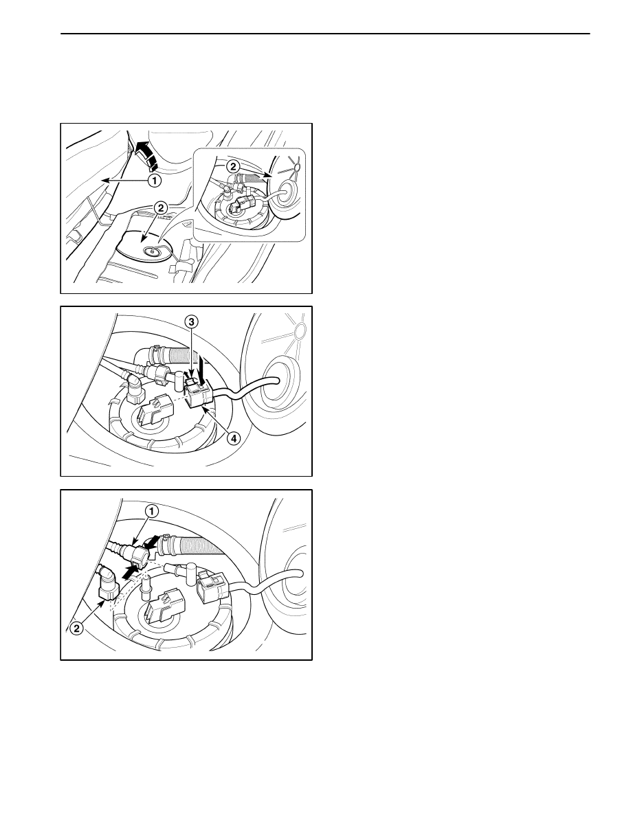
Caution: The fuel system is under pressure. To
avoid fuel spillage and the risk of personal injury or
fire, it is necessary to relieve the fuel system pres-
sure before disconnecting the fuel lines.
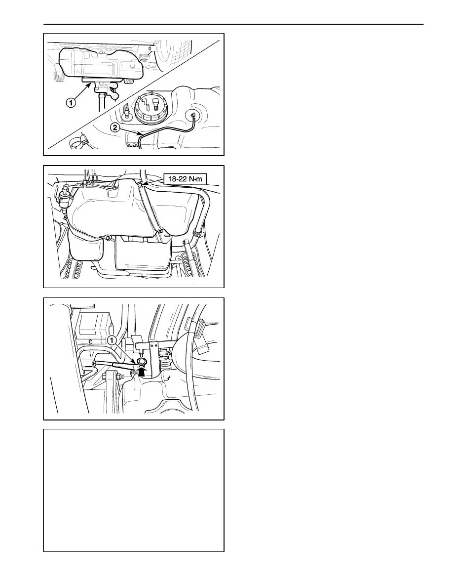
1. Relieve the fuel system pressure.
D
Start the engine and remove the rear seat cushon
(1).
D
Remove the fuel pump access cover (2).
D
Disconnect the fuel pump assembly electrical con-
nector lock pin (3).
D
Disconnect the fuel pump assembly electrical con-
nector (4).
D
Crank the engine for an additional 10 seconds.
D102F503
2. Disconnect the fuel lines from the fuel pump.
D
Disconnect the fuel outlet line (1).
D
Disconnect the fuel tank return line (2).
ENGINE CONTROLS 1F – 305
DAEWOO M-150 BL2
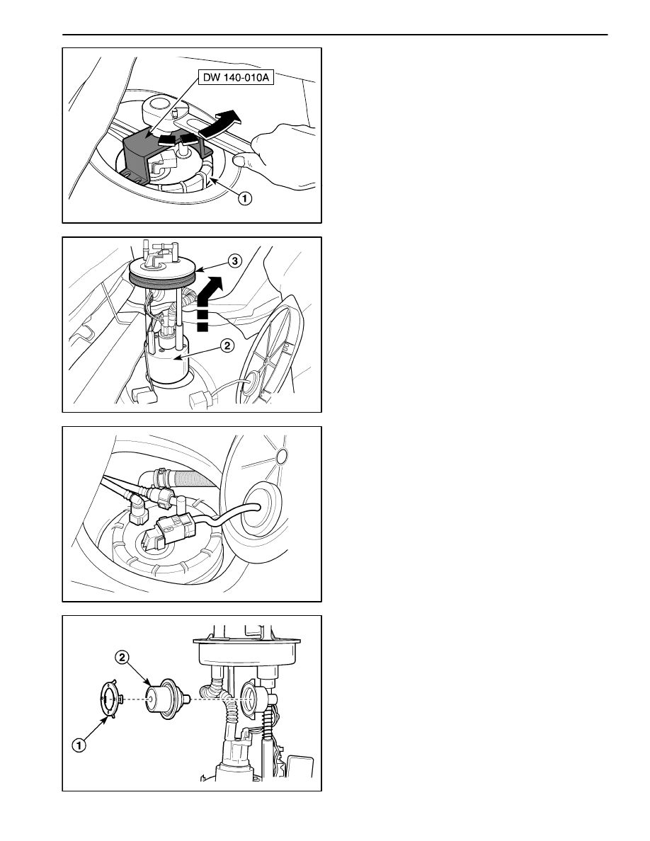
D12F504A
3. Remove the fuel pump assembly from the tank.
D
Install the fuel pump lock ring remover/installer DW
140– 010A.
D
Turn the fuel tank lock ring counterclockwise (1).
D102F505
D
Remove the fuel pump assembly (2).
D
Remove the fuel pump gasket (3).
D102F506
Installation Procedure
1. Install in the reverse order of removal.
2. Perform an operational check of the fuel pump.
D
Perform an operational check of the ignition switch
ON the 2 seconds fuel pump operation.
D102F507
FUEL PRESSURE REGULATOR
Removal Procedure
Caution: The fuel system is under pressure. To
avoid fuel spillage and the risk of personal injury or
fire, it is necessary to relieve the fuel system pres-
sure before disconnecting the fuel lines.
1. Relieve the fuel system pressure after remove the
fuel pump assembly. Refer to “Fuel Pump” in this
section.
1F – 306 ENGINE CONTROLS
DAEWOO M-150 BL2
D102F508
2. Remove the fuel pressure regulator from the fuel
pump.
D
Remove the retainer from the fuel pump assembly
(1).
D
Remove the fuel pressure regulator (2).
D
Check the O–ring seals for the damage or the rip.
D
Use a vacuum gauge to check the diaphram for
damage and the spring for operation.
D102F509
Installation Procedure
1. Install in the reverse order of removal.
D
Do not reuse the removed O–ring seals. Replace
the removed O–ring seals with the new ones.
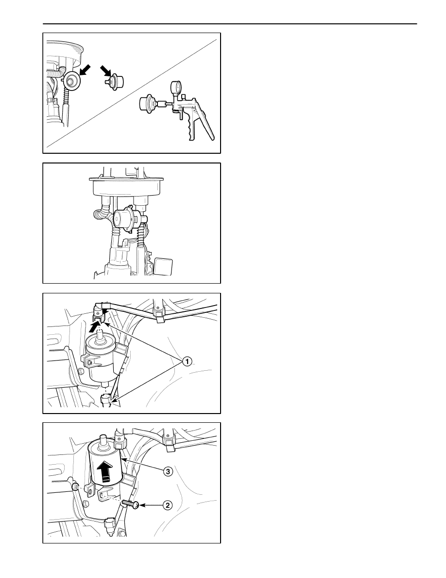
D102F511
D102F510
FUEL FILTER
Removal Procedure
Caution: The fuel system is under pressure. To
avoid fuel spillage and the risk of personal injury or
fire, it is necessary to relieve the fuel system pres-
sure before disconnecting the fuel lines.
1. Relieve the fuel system pressure.
Refer to “Fuel Pump” in this section.
2. Remove the fuel filter from the fuel tank.
D
Disconnect the inlet/outlet fuel lines by pushing the
line connector lock and pulling off the hose of the
fuel filter tube (1).
D
Remove the screw from the retaining clamp (2).
D
Remove the fuel filter (3).
ENGINE CONTROLS 1F – 307
DAEWOO M-150 BL2
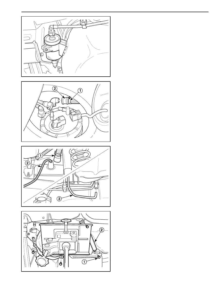
D102F512
Installation Procedure
1. Install in the reverse order of removal.
D
Install the new fuel filter into the retaining clamp.
Note the flow direction.
D
Connect the inlet/outlet lines. Secure the lines with
the connector lock.
D
Perform a leak test of the fuel filter.
D102F514
D102F513
FUEL TANK
Removal Procedure
Caution: The fuel system is under pressure. To
avoid fuel spillage and the risk of personal injury or
fire, it is necessary to relieve the fuel system pres-
sure before disconnecting the fuel lines.
1. Relieve the fuel system pressure.
Refer to “Fuel Pump” in this section.
2. Disconnect the fuel tank ventilation tube.
D
Disconnect the clamp (1).
D
Disconnect the ventilation tube (2).
3. Drain the fuel tank.
D
Place a pan below the fuel tank to catch the drain-
ing fuel.
D
Disconnect the fuel tank filter tube (1).
D
Drain the fuel from the fuel tank using the ventila-
tion tube joint port (2).
D
Disconnect the evaporative emission canister line
(3).
D12F515A
4. Remove the fuel filter. Refer to “Fuel Filter” in this
section.
5. Install the jack to remove the fuel tank.
D
Install the jack on the center of the fuel tank.
D
Remove the strap bolts (1).
D
Remove the straps (2).
1F – 308 ENGINE CONTROLS
DAEWOO M-150 BL2
D102F516
6. Remove the fuel tank.
D
Lower slowly the jack to remove the fuel tank easi-
ly (1).
D
Disconnect the canister hose which is connected
to the roll over valve from the fuel tank removed
(2).
D
Inspect the fuel tank for clacks, damages, and con-
taminations.
D
Inspect the fuel lines for cracks and damages.
D12F517A
Installation Procedure
1. Install in the reverse order of removal.
D
After the installation is complete, start the engine
to prevent the vapor lock and check the hoses for
leaks.
2. Install the fuel tank strap bolts.
Tighten
Tighten the fuel tank strap bolts to 18–22 N
S
m (13–16
lb-ft).
D102F519
D102F518
FUEL RAIL AND INJECTORS
Removal Procedure
Caution: The fuel system is under pressure. To
avoid fuel spillage and the risk of personal injury or
fire, it is necessary to relieve the fuel system pres-
sure before disconnecting the fuel lines.
1. Relieve the fuel system pressure.
Refer to “Fuel Pump” in this section.
2. Remove the canister from the engine room. Refer to
“Evaporative Emission Canister” in this section.
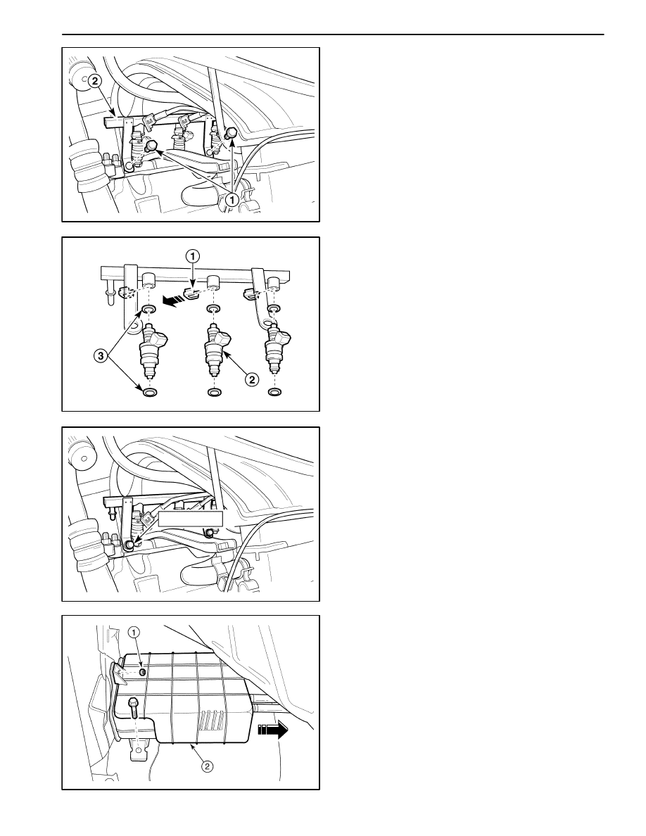
3. Disconnect the fuel inlet line (1).
4. Disconnect the fuel injector harness connectors (2).
ENGINE CONTROLS 1F – 309
DAEWOO M-150 BL2
D102F520
5. Remove the fuel rail with the fuel injectors attached.
D
Remove the bolts (1).
D
Remove the fuel rail with the fuel injectors attached
(2).
Notice: Before removal, the fuel rail assembly may be
cleaned with a spray–type cleaner, following package in-
structions. Do not immerse the fuel rails in liquid clean-
ing solvent. Use care in removing the fuel rail assembly
to prevent damage to the electrical connectors and the
injector spray tips. Prevent dirt and other contaminants
from entering open lines and passages. Fittings should
be capped and holes plugged during service.
D102F521
6. Remove the injectors from the fuel rail.
D
Remove the fuel injector retainer clips (1).
D
Remove the fuel injectors by pulling them down
and out (2).
D
Discard the fuel injector O–rings (3).
Important: Different fuel injectors are calibrated for dif-
ferent flow rates. When ordering new fuel injectors, be
certain to order the identical part number that is in-
scribed on the old fuel injector.
D12F522A
18–22 N
S
m
Installation Procedure
1. Install in the reverse order of removal.
Important: If a fuel injector becomes separated from
the fuel rail and remains in the cylinder head, replace the
fuel injector O–ring seals and the retaining clip.
D
Lubricate the new fuel injector O–rings with engine
oil. Install the new O–rings on the fuel injectors.
2. Install the fuel rail retaining bolts.
Tighten
Tighten the fuel rail retaining bolts to 18–22 N
S
m
(13–16 lb-ft).
3. Perform a leak check of the fuel rail and the fuel injec-
tors.
MAA1F400
EVAPORATIVE EMISSION CANISTER
Removal Procedure
Caution: Canister and vacuum hoses contain fuel
vapors. Do not smoke in the area or permit an open
flame.
1. Disconnect the negative battery cable.
2. Remove the canister.
D
Remove the bolt (1).
D
Remove the nut, then remove the cover (2).
1F – 310 ENGINE CONTROLS
DAEWOO M-150 BL2
MAA1F410
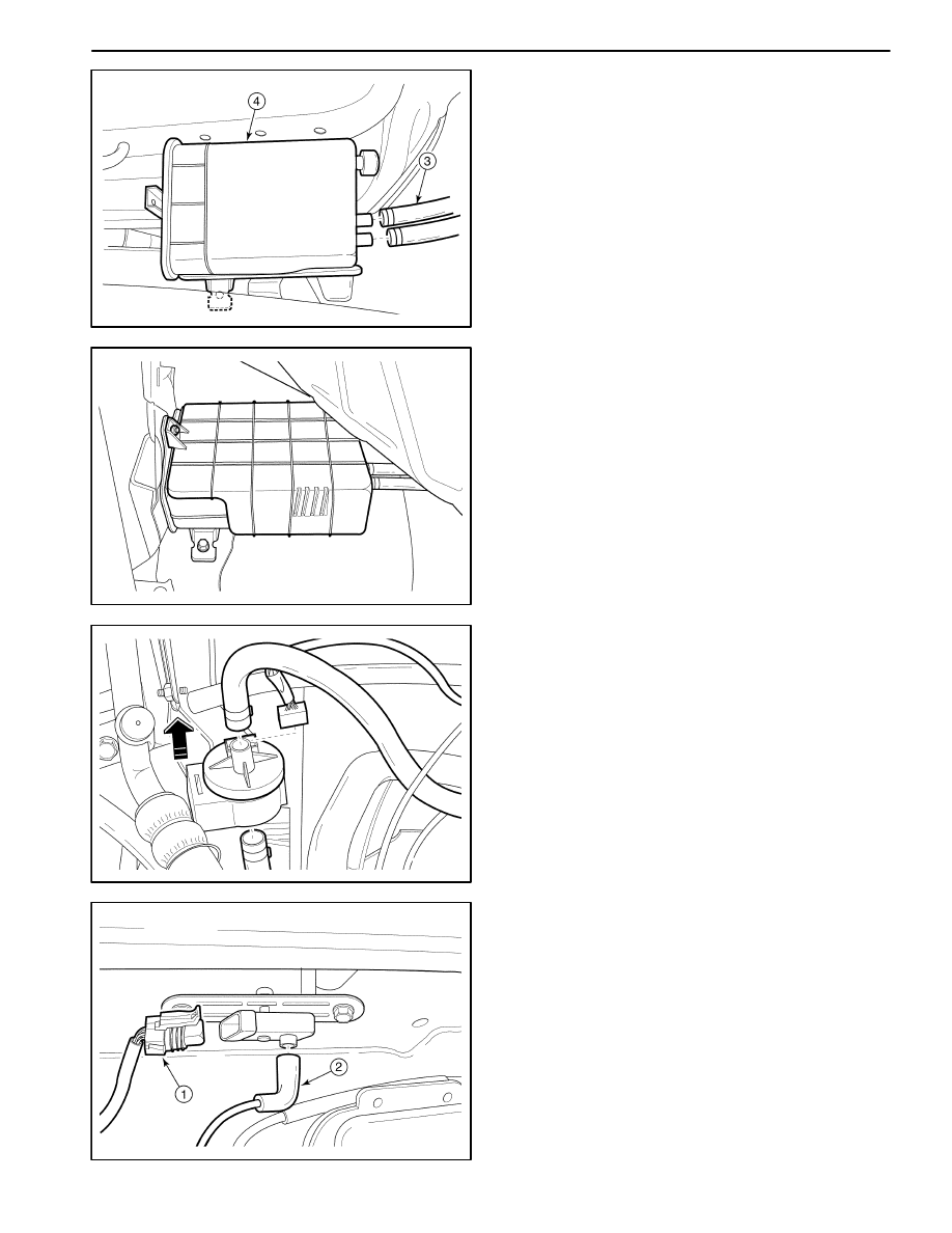
D
Disconnect the canister hoses (3).
D
Remove the evaporative emission casnister (4).
MAA1F420
Installation Procedure
1. Install in the reverse order of removal.
MAA1F430
EVAPORATIVE EMISSION CANISTER
PURGE SOLENOID
1. Disconnect the negative battery cable.
2. Disconnectthe evaporative (EVAP) emission canister
purge solenoid connector.
3. Disconnect the vacuum hoses from the EVAP canis-
ter purge solenoid.
4. Unclip the EVAP emission canister purge solenoid
from the mounting bracket.
5. Installation should follow the removal procedure in
the reverse order.
MAA1F440
MANIFOLD ABSOLUTE PRESSURE
SENSOR
Removal Procedure
1. Disconnect the manifold absolute pressure (MAP)
sensor connector and vacuum hose.
D
Disconnect the MAP connector (1).
D
Disconnect the vacuum hose from the MAP sensor
(2).
ENGINE CONTROLS 1F – 311
DAEWOO M-150 BL2
MAA1F450
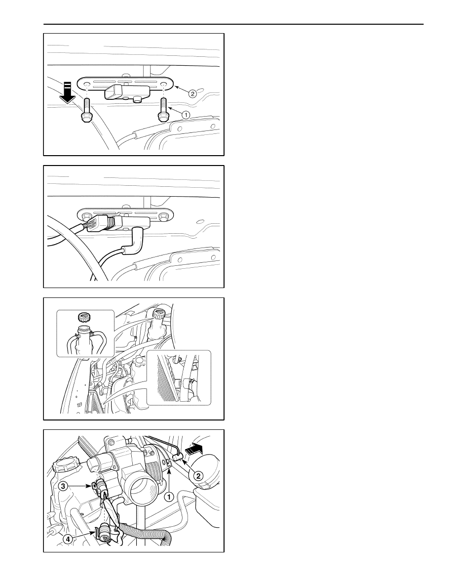
2. Remove the MAP sensor.
D
Remove the bolts (1).
D
Remove the MAP sensor with bracket (2).
MAA1F460
Installatin Procedure
1. Install in the reverse order of removal.
D
Inspect the MAP sensor vacuum hose for the tear
and damages.
2. Install the MAP sensor with the bolts and nuts.
Tighten
Tighten the MAP sensor bolts/nuts to 8–12 N
S
m
(71–106 lb-in).
Tighten the MAP sensor bracket bolt to 8–12 N
S
m
(71–106 lb-in).
D102F537
THROTTLE BODY
Removal Procedure
1. Remove the air cleaner/resonator assembly and air
intake tube. Refer to Section 1B, SOHC Engine Me-
chanical.
2. Drain the engine coolant. Refer to Section 1D, Engine
Cooling.
D102F538
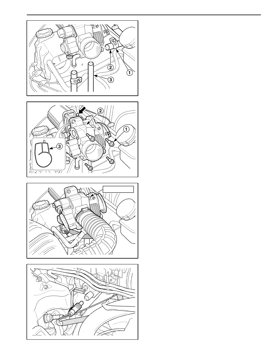
3. Disconnect the throttle cable, the throttle position
sensor and the idle air control valve connectors.
D
Open the throttle valve (1).
D
Disconnect the throttle cable (2).
D
Disconnect the idle air control valve connector (3).
D
Disconnect the throttle position sensor connector
(4).
1F – 312 ENGINE CONTROLS
DAEWOO M-150 BL2
D102F539
4. Disconnect the coolant hoses and vacuum hoses
from the throttle body.
D
Loosen the clamps from the coolant hoses (1).
D
Disconnect the coolant hoses from the throttle
body (2).
D
Disconnect the vacuum hoses (3).
D102F541
5. Remove the throttle body from the intake manifold.
D
Remove the throttle body bolts (1).
D
Remove the throttle body (2).
D
Discard the throttle body gasket (3).
D
Inspect the throttle body gasket for the deforma-
tion and the damages.
9–12 N
S
m
D12F542A
Installation Procedure
1. Install in the reverse order of removal.
Important: Make sure the throttle control cable do not
hold the throttle open. With the engine OFF, check to
see that the accelerator pedal is free.
2. Install the throttle body with the bolts.
Tighten
Tighten the throttle body bolts to 9–12 N
S
m (80–106
lb-in).
D12F543A
ENGINE COOLANT TEMPERATURE
(ECT) SENSOR
Removal Procedure
1. Remove the engine coolant temperature (ECT) sen-
sor. Refer to Section 1D, Engine Coolings.
ENGINE CONTROLS 1F – 313
DAEWOO M-150 BL2
D12F543B
Installation Procedure
1. Install the engine coolant temperature sensor.
Tighten
Tighten the engine coolant temperature sensor to
8–12 N
S
m (71–106 lb-ft).
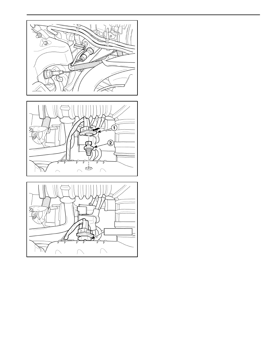
D102F544
INTAKE AIR TEMPERATURE (IAT)
SENSOR
Removal Procedure
1. Disconnect the negative battery cable.
2. Remove the intake air temperature (IAT) sensor.
D
Disconnect the IAT sensor connector (1)
D
Disconnect the IAT sensor.
20–30 N
S
m
D12F545A
Installation Procedure
1. Install in the reverse order of removal.
2. Install the IAT sensor.
Tighten
Tighten the IAT sensor to 20–30 N
S
m (15–22 lb-ft).
1F – 314 ENGINE CONTROLS
DAEWOO M-150 BL2
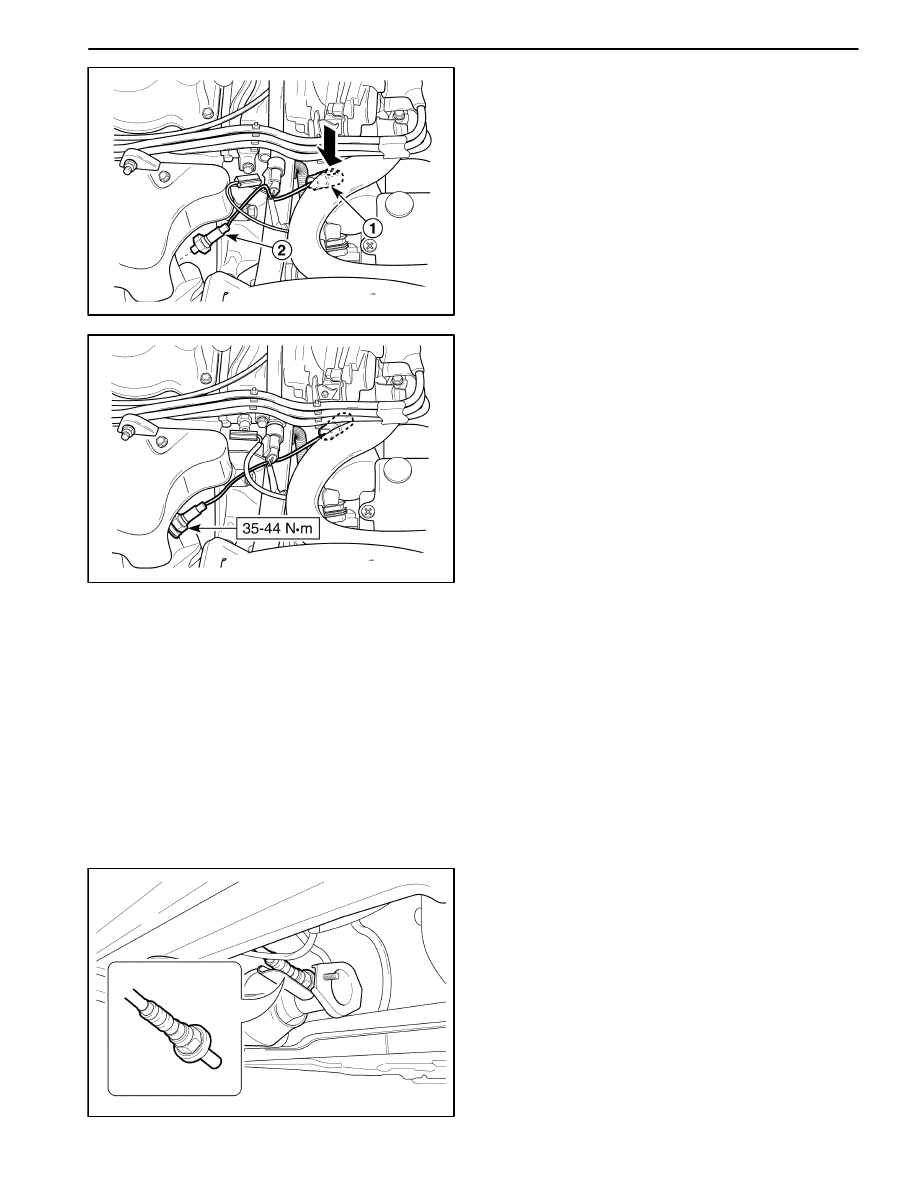
D102F546
OXYGEN SENSOR (O2S1)
Removal Procedure
1. Remove the air cleaner/resonator assembly. Refer to
Section 1B, SOHC Engine Mechanical.
2. Remove the oxygen sensor.
D
Disconnect the oxygen sensor connector (1).
D
Remove the oxygen sensor (2).
Notice: The oxygen sensor uses a permanently at-
tached pigtail and connector. This pigtail should not be
removed from the oxygen sensor. Damage or removal
of the pigtail or the connector could affect proper opera-
tion of the oxygen sensor. Take care when handling the
oxygen sensor. Do not drop the oxygen sensor.
D12F547A
Installation Procedure
1. Install in the reverse order of removal.
Important: A special anti–seize compound is used on
the oxygen sensor threads. This compound consists of
a liquid graphite and glass beads. The graphite will burn
away, but the glass beads will remain, making the sen-
sor easier to remove. New or service sensors will al-
ready have the compound applied to the threads. If a
sensor is removed from any engine and if for any reason
it is to be reinstalled, the threads must have anti–seize
compound applied before reinstallation.
2. Install the oxygen sensor.
Tighten
Tighten the oxygen sensor to 35~44 N
S
m (26~33 lb-
ft).
MAA1F470
HEATED OXYGEN SENSOR (HO2S2)
Removal and Installation Procedure
1. Disconnect the negative battery cable.
2. Remove the front center console.
3. Disconnect the HO2S2 connector.
4. Remove the front exhaust pipe. Refer to Section 1G,
Engine Exhaust.
5. Remove the HO2S2 from the front exhaust pipe.
Installation Procedure
1. Install in the reverse order of removal.
ENGINE CONTROLS 1F – 315
DAEWOO M-150 BL2
Important: A special anti–seize compound is used on
the oxygen sensor threads. This compound consists of
a liquid graphite and glass beads. The graphite will burn
away, but the glass beads will remain, making the sen-
sor easier to remove. New or service sensors will al-
ready have the compound applied to the threads. If a
sensor is removed from any engine and if for any reason
it is to be reinstalled, the threads must have anti–seize
compound applied before reinstallation.
2. Install the oxygen sensor.
Tighten
Tighten the oxygen sensor to 35~44 N
S
m (26~33 lb-
ft).
MAA1F480
EXHAUST GAS RECIRCULATION
VALVE
Removal Procedure
1. Disconnect the negative battery cable.
2. Remove the air cleaner assembly.
3. Disconnect the electric exhaust gas recirculation
(EEGR) valve connector.
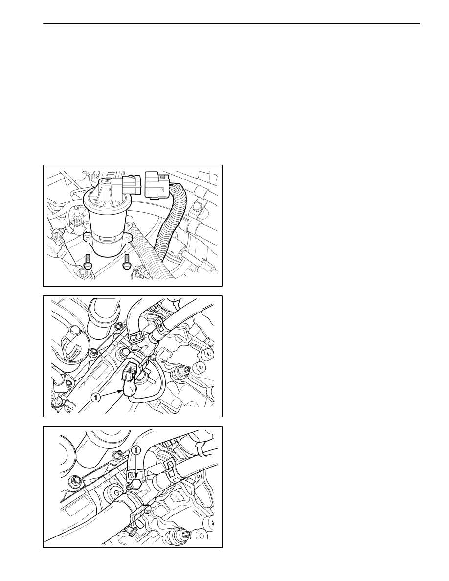
D21F008
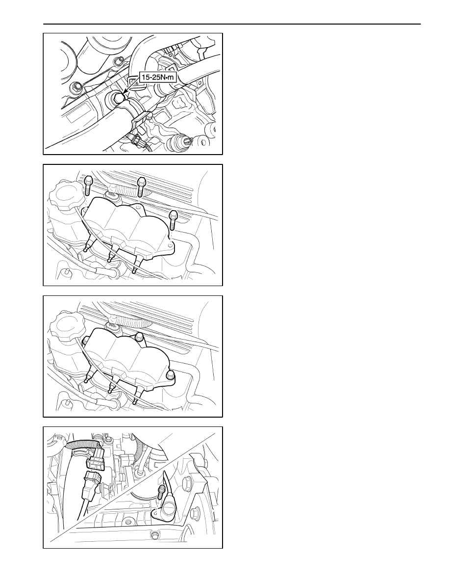
KNOCK SENSOR
Removal Procedure
1. Disconnect the negative battery cable.
2. Remove the starter. Refer to Section 1E, Engine
Electrical.
3. Disconnect the electrical connector at the knock sen-
sor (1).
D21F009
4. Remove the knock sensor.
D
Remove the knock sensor retaining bolt (1).
D
Remove the knock sensor.
1F – 316 ENGINE CONTROLS
DAEWOO M-150 BL2
D21F010
Installation Procedure
1. Install the knock sensor with the bolt.
Tighten
Tighten the knock sensor retaining bolt to 15–25 N
S
m
(11–18 lb-ft).
2. Connect the electrical connector to the knock sensor.
3. Install the starter. Refer to Section 1E, Engine Electri-
cal.
4. Connect the negative battery cable.
MAA1F490
ELECTRONIC IGNITION (EI) SYSTEM
IGNITION COIL
Removal Procedure
1. Disconnect the negative battery cable.
2. Note the ignition wire location and disconnect the
ignition wires from the EI system ignition coil.
3. Disconnect the EI system ignition coil connector.
4. Remove the EI system ignition coil retaining bolts.
5. Remove the EI system ignition coil.
MAA1F500
Installation Procedure
1. Install the EI system ignition coil.
2. Tighten the EI system ignition coil to 8–12 N
S
m
(71–106 lb-in).
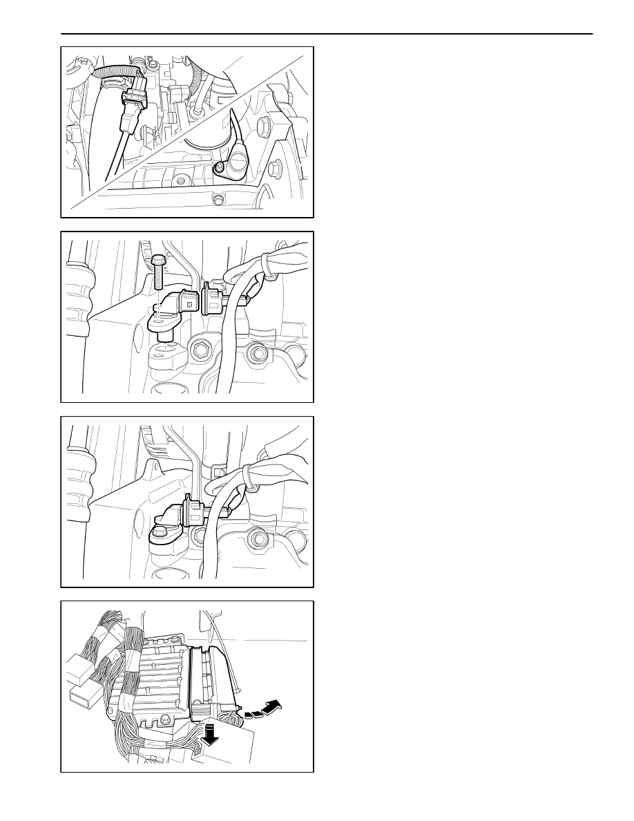
UAA1F2C0
CRANKSHAFT POSITION (CKP)
SENSOR
Removal Procedure
1. Disconnect the negative battery cable.
2. Remove the air cleaner assembly.
3. Disconnect the crankshaft position (CKP) sensor
connector.
4. Remove the CKP sensor retaining bolt.
ENGINE CONTROLS 1F – 317
DAEWOO M-150 BL2
MAA1F550
Installation Procedure
1. Install the CKP sensor.
2. Tighten the CKP sensor retaining bolt to 5–8 N
S
m
(44–71 lb-in).
UAA1F2E0
CAMSHAFT POSITION (CMP)
SENSOR
Removal Procedure
1. Disconnect the negative battery cable.
2. Disconnect the camshaft position (CMP) sensor con-
nector.
3. Remove the CMP sensor retaining bolt.
4. Remove the CMP sensor.
MAA1F540
Installation Procedure
1. Install the CMP sensor.
2. Tighten the CMP sensor retaining bolt to 10–14 N
S
m
(89–124 lb-in).
MAA1F510
ENGINE CONTROL MODULE (ECM)
Removal Procedure
1. Disconnect the ECM connector.
1F – 318 ENGINE CONTROLS
DAEWOO M-150 BL2
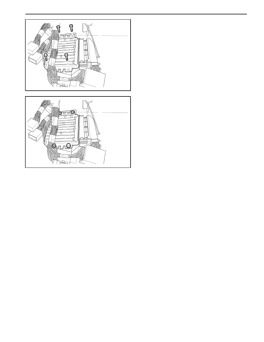
MAA1F520
2. Remove the ECM.
D
Remove the bolts.
D
Remove the ECM.
MAA1F530
Installation Procedure
1. Install in the reverse order of removal.
Notice: If disconnecting the battery cable to the ECM,
the IAC valve resetting should be proceeded.
2. install the ECM with the bolts.
Tighten
Tighten the ECM mounting bolts to 6–8 N
S
m (53–71
lb-in).
ENGINE CONTROLS 1F – 319
DAEWOO M-150 BL2
SPECIFICATIONS
FASTENER TIGHTENING SPECIFICATIONS
Application
N
S
m
Lb-Ft
Lb-In
Camshaft Position Sensor Bolts
10–14
–
89–124
Engine Coolant Temperature (ECT) Sensor
8–12
–
71–106
Crankshaft Position (CKP) Sensor Retaining Bolt
5–8
–
44–71
Electronic Ignition (EI) System Ignition Coil Retaining
Bolts
8–12
–
71–106
Evaporative Emission Canister Protective Cover
8
–
71
Electric Exhaust Gas Recirculation (EEGR) Valve
Retaining Bolts
20–30
15–22
–
Fuel Rail Retaining Bolts
18–22
13–16
–
Fuel Tank Strap Retaining Nuts
18–22
13–16
–
Knock Sensor Bolt
15–25
11–18
–
Intake Air Temperature (IAT) Sensor
20–30
15–22
–
Manifold Absolute Pressure (MAP) Sensor Retaining
Bolt
8–12
–
71–106
Oxygen Sensor
35–44
26–33
–
Heated Oxygen Sensor
35–44
26–33
–
Throttle Body Retaining Bolt
9–12
–
80–106
ECM Mounting Bolts
6–8
–
53–71
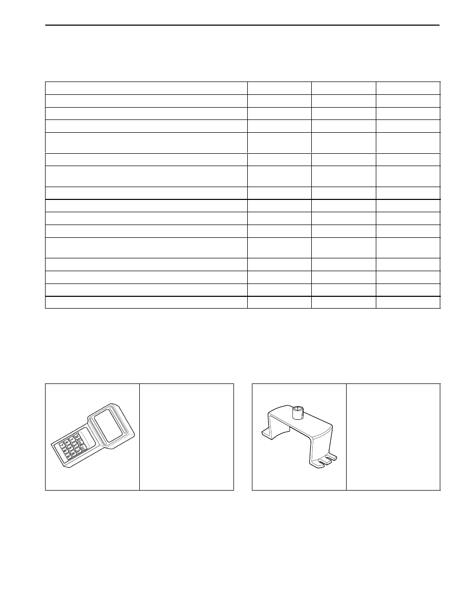
SPECIAL TOOLS
SPECIAL TOOLS TABLE
D102F101
Scan Tool
D12F102A
DW–140–010A
Fuel Pump Lock Ring
Remover/Installer
1F
–
320
ENGINE CONTROLS
DAEWOO M-150 BL2
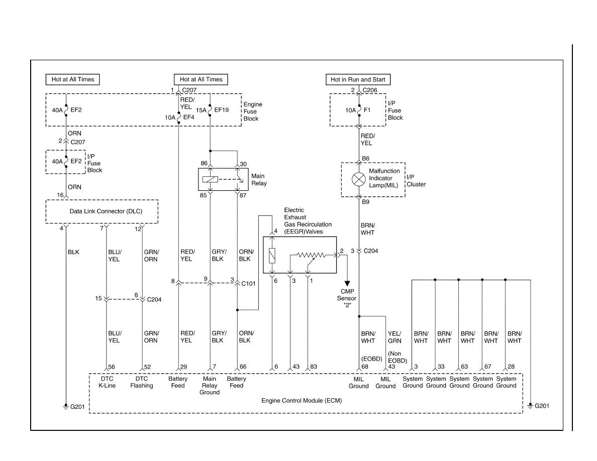
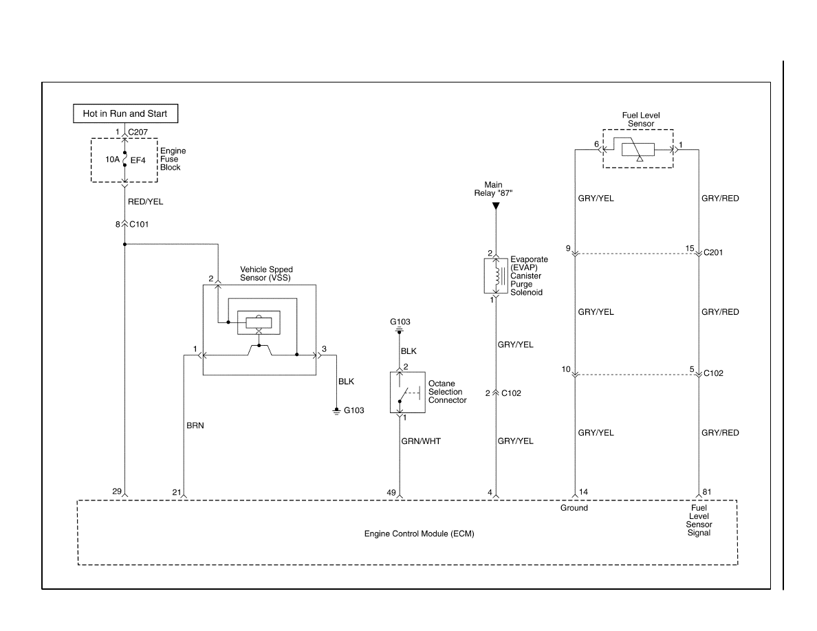
ECM WIRING DIAGRAM (SIRIUS D3 – 1 OF 5)
MAA1F610
ENGINE
CONTROLS 1F
–
321
DAEWOO M-150 BL2
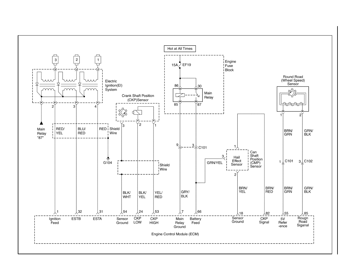
ECM WIRING DIAGRAM (SIRIUS D3 – 2 OF 5)
MAA1F620
1F
–
322
ENGINE CONTROLS
DAEWOO M-150 BL2
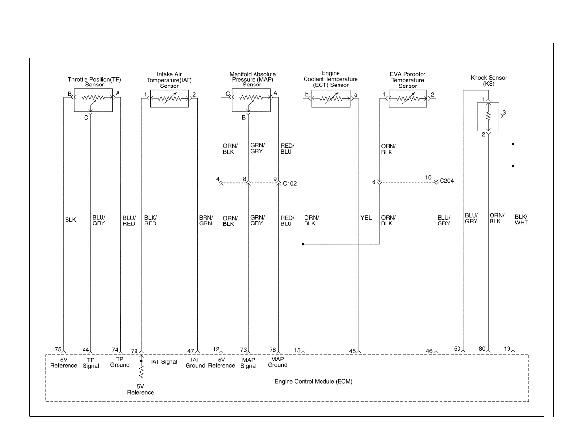
ECM WIRING DIAGRAM (SIRIUS D3 – 3 OF 5)
MAAF630
ENGINE
CONTROLS 1F
–
323
DAEWOO M-150 BL2
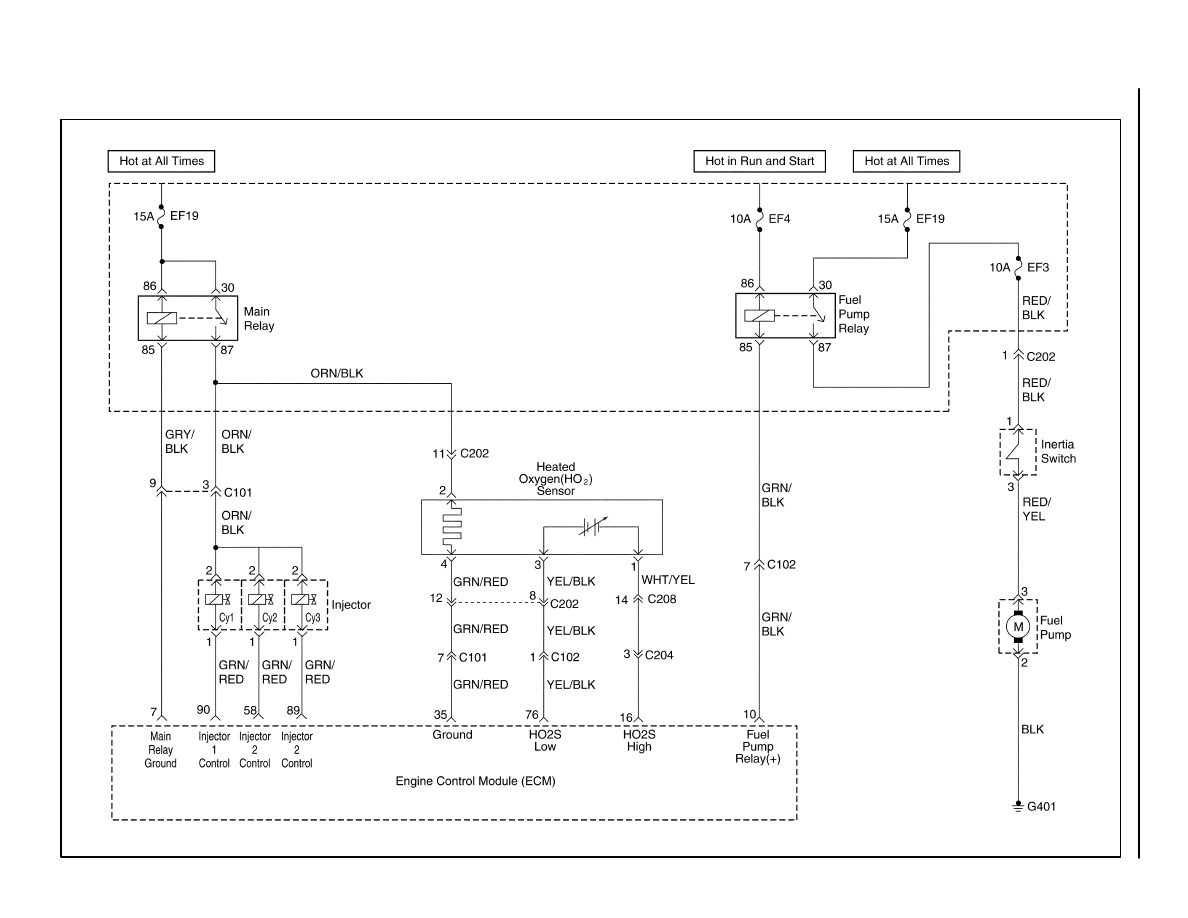
ECM WIRING DIAGRAM (SIRIUS D3 – 4 OF 5)
MAA1F640
1F
–
324
ENGINE CONTROLS
DAEWOO M-150 BL2
ECM WIRING DIAGRAM (SIRIUS D3 – 5 OF 5)
MAA1F650
Wyszukiwarka
Podobne podstrony:
M31f1 Engine Controls 1 54
10 Engine Control System
Computer engine control
ENGINE CONTROL SYSTEM
10 Engine Control System
M31f3 Engine Controls 152 279
Engine Control V6
Engine Control I4
Engine Control I4
Engine Control V6
M31f2 Engine Controls 55 151
M31f1 Engine Controls 1 54
10 Engine Control System
Computer engine control
ENGINE CONTROLS SECTION 1F 14
ENGINE CONTROLS 1F 28
więcej podobnych podstron