
382
ETHYLENE POLYMERS, CHLOROSULFONATED
Vol. 2
ETHYLENE POLYMERS, HDPE
Introduction
Polyethylene (PE) is the most widely used plastic throughout the world, and high
density PE (HDPE) is the most widely used type of PE. HDPE has generally been
taken to mean the product of ethylene polymerization having density greater than
about 0.935 (or 0.94). It includes ethylene homopolymers and also copolymers
of ethylene and alpha-olefins such as 1-butene, 1-hexene, 1-octene, or 4-methyl-
1-pentene. Other types of PE include low density PE (LDPE), made through a
free-radical process, and linear low density PE (LLDPE).
An analysis of commercial usage of the world’s major plastic types is shown
in Table 1. In terms of amount consumed, PE dominates the other types. Table 2
lists the U.S. usage of the various types of PE. In comparison to the other types of
PE, HDPE is by far the most versatile. HDPE consumption in the United States
accounted for about 6.95 billion kilograms per year in 1999, or almost half of total
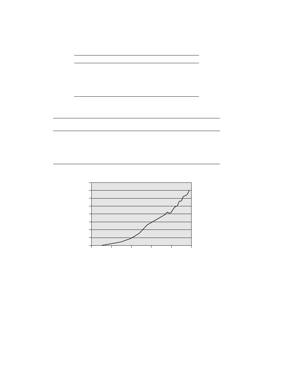
U.S. production of all PE types. Figure 1 shows how the demand for HDPE in the
United States has developed historically since its invention in 1951.
History of PE
Early Work.
The history of HDPE (and polyolefins in general) actually be-
gan in the 1890s with the synthesis of “polymethylene” from the decomposition of
diazomethane. Between 1897 and 1938, numerous reports of such polymers ap-
peared in the literature (1–6). Catalysts such as unglazed china, amorphous boron,
and boric acid esters were used for the decomposition. The empirical formula of
such products was found to be CH
2
. Later reproductions of work (3,6) established
Encyclopedia of Polymer Science and Technology. Copyright John Wiley & Sons, Inc. All rights reserved.
Vol. 2
ETHYLENE POLYMERS, HDPE
383
Table 1. Worldwide Usage of the Most Common Plastics Types
Polymer type
Share of world usage, %
PE (LDPE, EVA, LLDPE, and HDPE)
40.3
Polypropylene
21.9
PVC
21.1
Polystyrene
11.6
ABS/SAN
5.1
Total
100
a
Data from Digest of Polymer Developments, Series I, Number 95, STR
Publishing, Enfield, Conn., May, 2000.
Table 2. Polyolefins Usage in the United States in 1999
Consumption in
U.S. polyolefin
U.S. Polyolefin
Polymers
United States, 10
6
t
consumption, %
consumption, %
Total PE
14.7
67.8
100
LDPE (including EVA)
3.6
16.6
24.5
LLDPE
4.1
19.1
28.2
HDPE
7.0
32.1
47.4
Total Polypropylene
7.0
32.3
Total Polyolefins
21.7
100
a
Data from Digest of Polymer Developments, Series I, Number 95, STR Publishing, Enfield, Conn.,
May, 2000.
Year
0
1950
1960
1970
1980
1990
2000
1
2
3
4
5
6
7
8
Consumption, 10
6
t
/y
ear
Fig. 1.
HDPE consumption in the United States.
that the polymethylene thus obtained was a high molecular weight linear polymer
having a melting point of 134–137
◦
C and a density of 0.964–0.970 g/cm
3
(7). Thus,
it can be stated that although no commercial use was initially made of it, HDPE
was discovered long before the well-known LDPE was introduced (8,9).
In another early approach Pichler (10) and Pichler and Buffleb (11) described
during 1938–1940 the preparation of high molecular weight (M
n
= 23,000) poly-
mers from the hydrogenation of carbon monoxide over ruthenium and cobalt

384
ETHYLENE POLYMERS, HDPE
Vol. 2
catalysts. The reported melting point of 132–134
◦
C and density of 0.980 g/cm
3
indicate again that linear HDPE was obtained.
Free-Radical Process.
The first commercial PE was developed by Im-
perial Chemical Industries from 1932 to 1938 using a free-radical process (12).
Ethylene was polymerized at high pressure (142 MPa or 1400 atm) and at about
180
◦
C. It was discovered by accident that oxygen impurity could serve as the ini-
tiator. An ICI British patent filed in 1936 (13) disclosed pressures of ca 50–300
MPa (500–3000 atm), temperatures of 100–300
◦
C, the necessity of removing heat
to control temperature, and the necessity of controlling the oxygen content of the
ethylene used.
The PE produced at this time had a melting point of 115
◦
C and a density of
0.91–0.92 g/cm
3
. In 1940, Fox and Martin (14) found by infrared analysis that there
were more methyl groups in the polymer than could be accounted for by the end
groups of a linear chain. Thus the importance of chain branching was recognized,
and subsequent studies of branching led to a better understanding of its effect
on mechanical properties and polymer morphology. This material is called low
density PE (LDPE) and is still in high commercial demand today. Further work
on the free-radical process extended the pressure. Larcher and Pease (15) disclosed
PE with densities of 0.95–0.97 g/cm
3
, melting points above 127
◦
C, and branching
of less than one side chain per 200 carbon atoms.
Transition-Metal Catalysts.
Today’s “low pressure” catalytic processes,
from which HDPE now comes, were discovered in the early 1950s. The term “low
pressure” refers to operating pressures of generally 1.4–6.9 MPa (200–1000 psig),
in contrast to the ICI free-radical process. Patent applications were filed by Stan-
dard Oil of Indiana (16), in 1951, by Phillips Petroleum (17) in early 1953, and by
Ziegler and co-workers (18) in late 1953.
The Standard Oil patent (16) describes a supported reduced molybdenum
oxide or cobalt molybdate on alumina, with the ethylene preferably contacting
the catalyst in an aromatic solvent to affect the polymerization. Operating tem-
peratures of 100–270
◦
C were disclosed and the molecular weight could be varied
from very high to low such as those of greases.
At about the same time (1951) it was discovered that supported chromium
oxide catalysts would also polymerize ethylene at low pressures to produce high
molecular weight polymers (17). Reaction temperatures were in the range of
60–190
◦
C. Polymer characteristics, particularly, molecular weight and molecu-
lar weight distribution, could be varied by reactor temperature, pressure, and
activation temperature of the “Phillips catalyst.”
Shortly thereafter, yet another transition-metal catalyst (Ziegler catalyst)
capable of polymerizing ethylene at low pressure was discovered in Germany (18).
This approach used a transitional metal halide, or other complex, activated by an
aluminum alkyl cocatalyst. Transition-metal compounds of Groups IVa through
VIa (Ti preferred) were claimed.
Although the Standard Oil discovery came first, commercialization was slow
(19,20). Three plants were eventually built between 1961 and 1971, but the pro-
cess had poor economics and was soon scrapped. In contrast, the Phillips and
Ziegler discoveries were both commercialized rapidly and still exist today in more
advanced forms. At Phillips, the first plants were brought on stream in 1955 and
1956. However, Phillips management concluded that no one manufacturer could
Vol. 2
ETHYLENE POLYMERS, HDPE
385
develop the full market potential of the Phillips HDPE and therefore decided to
license the process. By 1956, nine companies in seven countries became licensees
(21–24). Ziegler also began to license his patent, following the discovery that good
activity could be obtained by use of titanium halides in combination with alu-
minum alkyls. However, the patent included only catalyst knowledge, and each
licensee had to develop a process. The first Ziegler plant was brought on stream
in late 1956 by Hoechst. A second one was built in 1957 by Hercules. By 1960 U.S.
production of HDPE via the Phillips process had reached over 91,000 t annually,
while 32,000 t came from the Ziegler process.
Today HDPE is still made almost entirely through chromium or Ziegler sys-
tems. The two systems produce different types of polymer, which is useful for
different applications. The Phillips catalyst generally produces broader molecu-
lar weight distributions than that of typical Ziegler catalysts.
Catalysts Used for HDPE Production
Chromium Catalysts.
The Phillips chromium catalyst, which perhaps
accounts for about half of the total HDPE production, is usually made by impreg-
nating a chromium compound onto a porous, high surface area oxide carrier, such
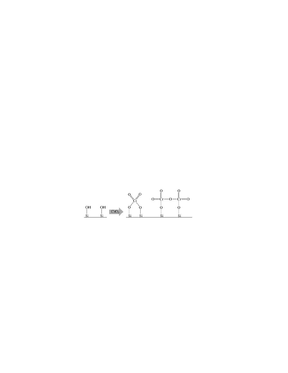
as silica, and then calcining it in dry air at 500–900
◦
C (25). This latter activa-
tion step converts the chromium into a hexavalent surface chromate, or perhaps
dichromate, ester. Because each Cr atom is individually attached to the surface,
the support is not inert but exerts a strong influence on the polymerization be-
havior of the site.
The first step in the development of polymerization activity occurs when
these hexavalent surface species are then reduced by ethylene in the reactor to
a lower valent active precursor, probably Cr(II) (25–28). Because Cr(VI) is tetra-
hedrally coordinated, and the reduced species can be octahedral, the resultant
expansion of the coordination sphere creates a high level of coordinative unsat-
uration which plays a role in the polymerization mechanism. Thus, the reduced
species chemisorbs olefin readily. However, this same trait makes the catalyst very
sensitive to small levels of polar impurities in the feed streams, such as alcohols,
water, amines, etc (29,30). Commercial catalysts usually contain about 1.0 wt%
Cr, but only a small fraction of this, perhaps 10–20% or even less, is actually active
for polymerization (25,27,30).
The second step in the development of polymerization activity is an alkyla-
tion reaction in which the first chain begins growing on the reduced chromium
species. Exactly how this reaction occurs has been unclear. Several possibilities
have been suggested over the years, but no clear answer has yet been established
(25,31–35). Recent studies suggest that initial adsorption of olefin on Cr(II) sites
may cause an oxidation to an alkylated Cr(IV) site as the active polymerization
386
ETHYLENE POLYMERS, HDPE
Vol. 2
Polymerization time
P
olymer
ization r
ate
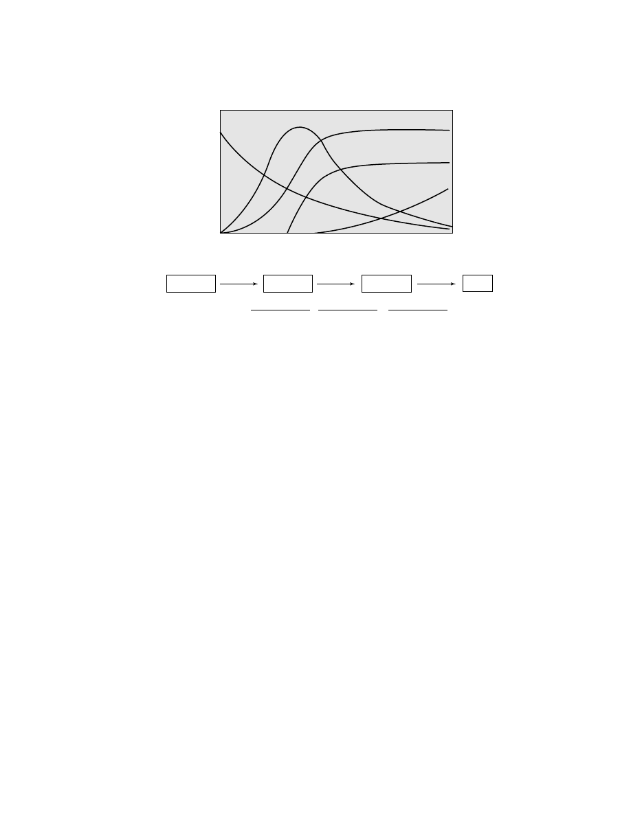
Fig. 2.
Kinetic profiles of Cr-based catalysts.
Oxidized
Alkylated
*
Dead
Reduced
k
1
k
2
k
3
[C
∗
]
= k
1
k
2
e
− k
1
t
(k
2
− k
1
)(k
3
− k
1
)
+
e
− k
2
t
(k
1
− k
2
)(k
3
− k
2
)
−
e
− k
3
t
(k
1
− k
3
)(k
2
− k
3
)
species (34,35). These two initial steps, reduction followed by alkylation, cause
the catalyst to display an induction time. That is, the onset of polymerization oc-
curs gradually after a delay which can last from a few minutes to over an hour
depending on reaction conditions (25,27).
Alternatively, the reduction step can also be accomplished before the catalyst
contacts ethylene in the reactor, by exposure to carbon monoxide at 350
◦
C (25,27).
In this case the reduced species has definitely been identified as Cr(II) (28,36–40).
This catalyst behaves much like its Cr(VI)/silica parent when introduced into the
reactor, producing similar polymer at similar activity in most cases. However, the
onset of polymerization often occurs more rapidly when the catalyst is prereduced,
since one step is omitted (25,27).
Once the polymerization reaction has developed, a decay in activity can also
sometimes be observed because of a chemical instability of the active species.
Thus, the kinetic profile of the polymerization reaction can be defined as a series
of three consecutive reactions: (1) reduction, (2) alkylation, and (3) decay. Each step
in the series has its own dependency on ethylene concentration, temperature, and
catalyst composition. Figure 2 shows some typical kinetic profiles that are often
obtained and that can be produced by varying the individual rate constants of the
three steps (41).
Metal alkyl cocatalysts, such as alkyl boron, aluminum, zinc, lithium, etc,
can also be added to the reactor as a way of enhancing the activity of the catalyst.
Such agents act by accelerating the reduction step, by alkylating the chromium, or
by scavenging minor amounts of poisons such as water and oxygen. These agents
are sometimes used commercially for specific resin types, although they are not
essential and in most cases are not used (41,42).
In another, less common, variation of the catalyst, lower valent
organochromium compounds can be deposited onto an already calcined support to
produce very active catalysts (43–51). These compounds react with surface hydrox-
yls to become attached to the support, often losing one or more ligands. Examples
Vol. 2
ETHYLENE POLYMERS, HDPE
387
include bisarene Cr(0), allyl Cr(II), and Cr(III), beta-stabilized alkyls of Cr(II) and
Cr(IV), and biscyclopentadienyl Cr(II). The latter example has been used commer-
cially to great extent. Such catalysts often develop activity more rapidly than the
chromium oxide catalysts, being already reduced and in some cases already alky-
lated. The remaining organic ligands can also change the polymer obtained in
certain ways.
The most common support used commercially is silica and silica–titania.
However, silica–alumina, alumina, and aluminophosphates can also be used
(52,53). Adding titania to the recipe enhances activity and broadens the molec-
ular weight distribution not because the titanium itself is active, but because it
influences the chromium (54). It is believed that some chromium sites become
attached to the titania, which thus indirectly influences the polymerization reac-
tion through electronic effects. Likewise, adding alumina, magnesia, boria, and
other oxides have unique effects. Aluminum phosphate is particularly interesting
in that it is isoelectronic and isostructural with silica, but of course the surface
chemistry is quite different, containing such diverse groups as P OH, P O, and
Al OH (41,52,53,55). Thus, changing the support can be a way of varying polymer
characteristics.
Ziegler Catalysts.
Titanium chloride based Ziegler catalysts are also
widely used throughout the HDPE industry. These catalysts generally produce
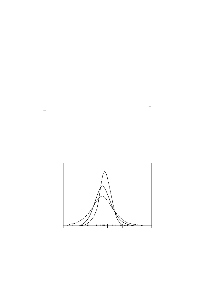
a narrower molecular weight distribution than that obtained from chromium ox-
ide catalysts. Figure 3 shows this typical distinction. Because of this, the Ziegler
catalysts are often used for different applications compared to chromium oxide.
While chromium oxide species may vary considerably in their local environ-
ment because of the heterogeneous nature of an amorphous oxide carrier, Ziegler
species are often thought to be more uniform, occupying certain places in a mi-
crocrystalline environment (56–58). Frequently, donor compounds, such as ethers,
Metallocene
Ziegler
Chromium
2
3
4
5
6
7
8
log
M
W
Fig. 3.
Molecular weight distribution (gpc curves) of resins derived from metallocene,
Ziegler, and chromium oxide based catalysts.

388
ETHYLENE POLYMERS, HDPE
Vol. 2
esters, and silane alkoxides, are added to neutralize or modify certain undesirable
sites (59).
The early commercial Ziegler catalysts were based on titanium(III) chloride,
often ball milled or otherwise treated to provide higher surface area. In about
1968, Hoechst introduced the so called high activity Ziegler catalysts, in which
the titanium was dispersed in a magnesium chloride lattice, into which it fitted
nicely (60–62). In this way the polymer yield per titanium atom was increased by
10-fold or more.
The transition-metal compound, usually a titanium(III) or titanium(IV) chlo-
ride, is transformed into the active catalytic species upon reaction with an alu-
minum alkyl cocatalyst. During this reaction the active metal becomes alkylated,
and ethylene is inserted into the metal–alkyl bond. Often the active site is con-
sidered to be a bridging complex between the transition metal and the alkyl alu-
minum compound, in which one or two ligands are shared between the two metals.
In some cases, broadening has been achieved by using vanadium, zirconium,
or other metal halides in the recipe, either alone or in combination with titanium
(63–65). In other cases, broadening has been achieved by providing two distinctly
different chemical environments for the titanium (66), or in the process by passing
the Ziegler catalyst through two or more reaction zones (67).
Metallocenes and Other Single-Site Catalysts.
One type of Ziegler cat-
alyst, based on cyclopentadienyl titanium or zirconium halides (which provided
only marginal activity using aluminum alkyls as cocatalysts) received an extreme
enhancement in activity in the mid-1970s with the discovery of methylalumi-
noxane (MAO) cocatalyst (68,69). Unlike traditional aluminum alkyl cocatalysts,
MAO is far more capable of ionizing the transitional metal compound (57,70–73).
Since that time other ionizing agents have also been developed, which are
capable of activating these “metallocene” compounds (74,75).
Metallocene catalysts differ from the traditional catalysts in that the site is
derived from a singular molecular species with defined ligands, unlike the het-
erogeneous character of chromium or Ziegler species. This accounts for the ultra-
narrow molecular weight distribution of the polymer obtained (see Fig. 3). Al-
though usually described as single-site catalysts, it is nevertheless clear on closer
inspection that many of these catalysts do not entirely fit the description because
the ionization agent is still part of the active site. MAO, the partial hydrolysis
product of trimethylaluminum, is also capable of providing a complex and varied
site environment.
Metallocene catalysts are at present just entering the market in certain spe-
cialty applications, accounting for perhaps less than 1% of all HDPE sales. How-
ever, the greater degree of control offered by metallocenes, and the ability to com-
bine different metallocenes into one catalyst, offers the ability for the first time to
truly tailor polymer architecture. Thus, it seems likely that future advancements
in single-site chemistry will have a profound impact on the HDPE market. The
influence of metallocenes on the LLDPE market has been somewhat greater to
date (see LLDPE). This has been mostly due to their ability to evenly distribute
branching over the molecular weight distribution. The result has been improved
film performance over traditional Ziegler systems.

Vol. 2
ETHYLENE POLYMERS, HDPE
389
Within the past 5 years, other types of new organo transitional metal com-
pounds have also been reported, which can be activated by ionizing agents like
MAO (76–78). Some of these compounds, such as Brookhart’s nickel diimine com-
plex, offer the possibility of producing highly branched ethylene homopolymers
that have never before been possible from low pressure systems. Thus, although
no commercial polymers are presently made from these systems, it seems likely
that these new catalyst developments will have a strong influence on the future
direction of HDPE markets.
Polymerization Mechanism and Reactor Control
Molecular Weight and Molecular Weight Distribution.
Once an active
site has been formed, through reduction and alkylation of chromium oxide species,
and once polymerization has been initiated, two reactions—propagation and ter-
mination (or chain transfer)—occur simultaneously and competitively. These cat-
alysts are not “living” systems, in which the polymer chain grows indefinitely.
Rather, the length of the chain formed is determined by the rate of propagation
relative to the rate of termination. On average in a commercial process, the life-
time of a chain on an active site is typically a small fraction of a second, say 0.1 s
or less. Since the lifetime of the catalyst in the reactor is usually 1–2 h, this means
that each site produces many chains before being discharged from the reactor.
For active chromium species on the Phillips catalyst, the rates of propagation
and termination are thought to be characteristic of the local geometry and ligand
field surrounding each site on the heterogeneous silica surface. Thus, different
sites tend to produce polymers of different average molecular weight, and the
overall molecular weight distribution of the polymer reflects the site heterogeneity
of the catalyst. This connection allows the molecular weight distribution to be
controlled by varying the composition and heat history of the catalyst.
The Schultz–Flory distribution has usually been considered as the simplest
model for representing the molecular weight distribution expected from a poly-
merization catalyst (79). It assumes that each site is identical and that the prob-
ability of termination is not dependent on the length of the growing chain. Thus
if the probability of propagation is considered to be p, and of termination to be
(1
−p), then the probability of producing a chain n units long would simply be
F(n)
= p
n
(1
−p). This distribution produces a breadth of molecular weight distri-
bution, or polydispersity (weight average/number average), of 2.0. In reality, typ-
ical chromium catalysts produce much broader molecular weight distributions,
with polydispersity values of 4–20. This is taken as an indication of multiple site
environments on these catalysts. Indeed this is also evident by the fact that the
molecular weight changes (increases) as the activity develops with time. Those
sites which come on stream first produce the lowest molecular weight. Some met-
allocene and other single-site catalysts, however, do approach the narrow theoret-
ical Schultz–Flory distribution of 2.0.
The propagation step, usually first order in ethylene concentration (80), is
thought to occur through the insertion of coordinated ethylene into the metal–
alkyl bond (56–58). Termination, or chain transfer, can occur through several
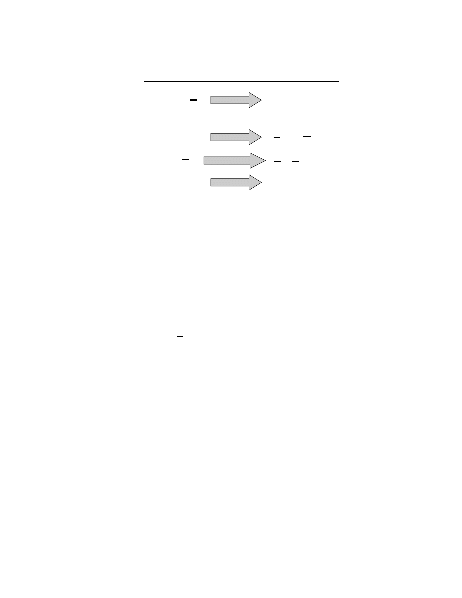
different mechanisms. Two of the most common reactions are shown in Figure 4
390
ETHYLENE POLYMERS, HDPE
Vol. 2
PROPAGATION
CHAIN TRANSFER
Cr
CH
2
CH
2
Chain
Cr
CH
2
CH
2
-Chain
Cr
H
+ CH
2
Cr-Chain
+ CH
2
CH
2
Cr-Chain
+ H
2
Cr-Chain
+ CH
2
CH
2
Transfer to Metal
Hydrogenation
Transfer to Monomer
CH Chain
Cr
H
+ H Chain
Cr
CH
2
CH
3
+ H Chain
-
-
-
-
Fig. 4.
Steps of polymerization.
as beta-H elimination (1) to monomer and (2) to the metal. Both reactions leave
a vinyl group on one end of the chain and a methyl on the other. In the former
case, the transfer step is dependent on ethylene concentration, while in the latter
case it is not. On many Ziegler and metallocene catalysts the primary transfer
mechanism is to monomer, so that the molecular weight is unrelated to ethylene
concentration (since both propagation and transfer are first order in ethylene).
However, on chromium oxide catalysts transfer to metal also becomes significant,
and this fact is used to control product molecular weight during commercial man-
ufacture. When ethylene concentration in the reactor is increased, the molecular
weight also increases (25).
Hydrogen can also be added to the reactor to control molecular weight for
most catalyst systems. When deuterium is used in place of hydrogen, the promi-
nent chain end-group
CH
2
D is observed (27). Metallocene and Ziegler catalysts
are more sensitive to hydrogen than most chromium oxide systems. In the latter
case, adding hydrogen to the reactor also tends to narrow the molecular weight
distribution, because the high molecular weight producing sites seem to be most
sensitive. Metal alkyls can also sometimes terminate chains through alkyl ex-
change. Aluminum, zinc, and boron alkyls have been reported to do this for some
catalyst systems. For chromium oxide catalysts there are indications that boron
alkyls are particularly potent and the process may even be catalytic (81). Again,
some sites seem to be more affected than others, which can be used to produce
special polymer effects (82).
Fracturing.
On silica supported catalysts, such as the Phillips chromium
oxide system and some Ziegler catalysts, the active sites are attached to the in-
ternal surface of pore walls. Within a minute or so after polymerization begins,
these pores become clogged with polymer. At this point, the silica particle begins
to fracture into perhaps a billion smaller fragments because of the internal pres-
sure created by polymer generation (25,83,84). This fracturing process only occurs
on certain high porosity (and thus friable) silicas which are specially prepared for
use as polymerization catalyst supports. Otherwise, fracturing does not take place
and the catalyst has little or no activity. These fragments, which may be as small
as 0.1
µm, then become engulfed in polymer, and unless the polymer is made in a

Vol. 2
ETHYLENE POLYMERS, HDPE
391
solution process, these subparticles are loosely held together by entwined polymer
into a larger polymer particle which replicates the shape of the original catalyst
particle. Each ton of catalyst produces some 2000–10,000 tons of polymer (or more)
before being discharged from the reactor. Each catalyst particle thus produces a
polymer particle of about the same shape, but many thousands of times its own
mass. The catalyst is left in the polymer as a minor impurity.
Polymer Structure
General Structure.
Commercial HDPE is a predominantly linear polymer
with the chemical composition roughly of polymethylene, (CH
2
)
n
. Its name reflects
the principal method of production: ethylene polymerization by transition-metal
catalysts. At least one end group of each chain contains a methyl group, and
depending on the method of manufacture, the other end group is also a methyl or
a vinyl group. Some general properties are shown in Table 3.
The weight-average molecular weight (M
w
) of typical commercial HDPE
grades can vary from 20,000 to over 1,000,000, depending on the application.
The molecular weight distribution of commercial HDPE polymers can range from
very narrow, for metallocene derived polymers, to very broad, for grades made
from chromium oxide catalysts. A convenient measure of the molecular weight
breadth is the polydispersity, or the ratio of the weight-average molecular weight
to the number-average molecular weight (M
w
/M
n
). Experimentally, the molecular
weight distribution is measured by gel-permeation chromatography (gpc).
Short-Chain Branching.
Although described as high density, commercial
HDPE can actually vary in density from 0.975 down to 0.935. HDPE contains a
crystalline phase and an amorphous phase, and the measured density directly
reflects the percentage of each. Typical homopolymer is normally about 94% crys-
talline and has a density of 0.960–0.965. Higher densities can be achieved by low
molecular weight and slow cooling.
Crystallinity is disrupted, and density therefore lowered, if branching is
added to the otherwise linear polymer backbone. This is typically accomplished
by copolymerizing alpha-olefins in small amounts with the ethylene. 1-Butene,
1-hexene, 1-octene, and 4-methyl-1-pentene are the comonomers most com-
monly used commercially, producing respectively ethyl, butyl, hexyl, and isobutyl
branches. On a weight basis, comonomer is usually added in an amount less than
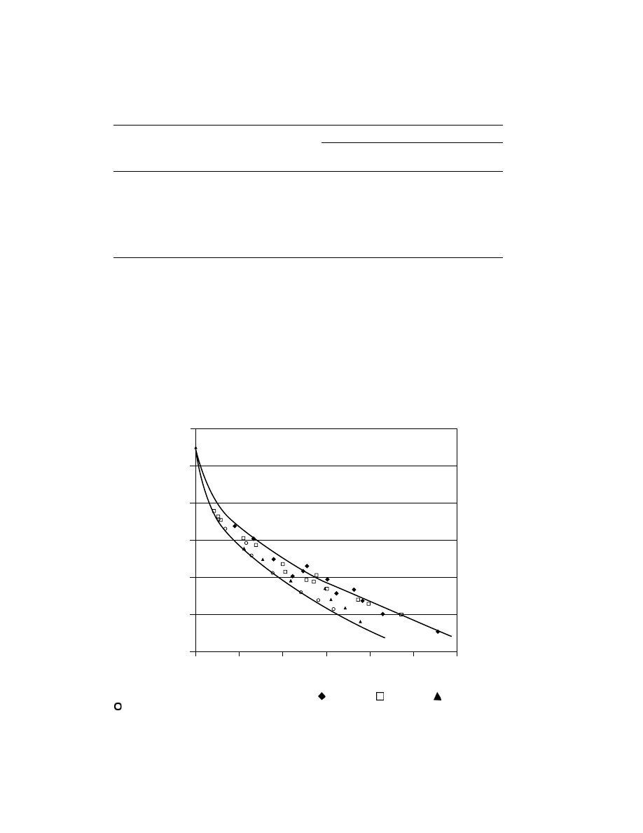
5% of the total composition. Figure 5 shows the relationship between density and
comonomer content.
Rheology and Long-Chain Branching.
Molten HDPE is a non-
Newtonian fluid at temperatures of 140–200
◦
C. Its effective viscosity is reduced
sharply, up to several thousand times, when the melt-flow speed is increased. The
viscosity of the polymer is also a function of its molecular weight. Non-Newtonian
behavior of the melt at low shear rates allows correlation of melt viscosity with
molecular weight. The reason for this behavior is disentanglement of polymer coils
at high shear rate and their partial orientation in the flow direction.
By convention, the most convenient and generally accepted representation of
melt viscosity is the “melt index”, which is the amount of polymer flowing through
a standard capillary viscosimeter at 190
◦
C under a 2.16-kg load for 10 min (ASTM

392
ETHYLENE POLYMERS, HDPE
Vol. 2
Table 3. Properties of Three Typical Commercial HDPE Grades
Resin Grade
Injection
Blow
Property
Test
molding
molding
Film
Physical
Melt index (2.16 kg)
ASTM D1238
33.59
0.36
0.31
High load melt index
ASTM D1238
High
34.14
23.22
(21.6 kg)
Density, g/cm
3
ASTM D1505
0.9678
0.9557
0.939
Refractive Index, n
D
25
1.54
1.53
1.51
Molecular Weight (weight
gpc
13,900
17,800
13,600
average M
w
)
Molecular Weight (number
gpc
48,400
143,000
177,000
average, M
n
)
Polydispersity (M
w
/M
n
)
gpc
3.5
8.0
13.1
Weight percent hexene
C
13
nmr
0.00
0.60
3.50
Mechanical
Yield point, MPa
a
ASTM D638
31.0
27.8
19.1
Tensile strength, MPa
a
ASTM D638
31.0
23.4
29.5
Tensile Impact, kJ/m
2b
ASTM D638
9.0
56.8
143.6
Elongation, %
ASTM D638
At yield point
ASTM D638
8.2
10.1
13
At break point
ASTM D638
8.2
669
745
Notched impact strength,
ASTM D256-84a
0.90
17.3
No Break
kJ/m
2b
Flexural modulus, MPa
a
ASTM D790-95a
1894
1375
822
Brinell hardness, MPa
a
60–70
50–60
35–50
Hardness (Shore D)
ASTM D2240
67
62
51
Environmental stress-
Condition A, h
ASTM D1693
0
49
>1000
crack resistance
Condition B, h
ASTM D1693
0
29
>1000
Condition C, h
ASTM D1693
0
0
>1000
Thermal
Melting point,
◦
C
136
133.5
127
Brittleness temp.
◦
C
ASTM D746
−140 to −70
Heat resistance temp.,
◦
C
ca 122
ca 120
ca 117
Vicat softening point,
◦
C
ASTM D1525
126
133
Specific heat capacity,
1.67–1.88
1.88–2.09
kJ/(kg
·K)
c
Thermal conductivity,
0.46–0.52
0.42–0.44
W/(m
·K)
Temp. coefficient of
(1–1.5)
× 10
− 4
linear expansion
Temp. coefficient of
(2–3)
× 10
− 4
volume expansion
Heat of combusion, kJ/g
c
46.0
Vol. 2
ETHYLENE POLYMERS, HDPE
393
Table 3. (Continued)
Resin Grade
Injection
Blow
Property
Test
molding
molding
Film
Electrical
Dielectric constant at 1 MHz
2.3–2.4
2.2–2.4
2.0–2.3
1 kHz–1 MHz
(2–4)
× 10
− 4
1 kHz–1 MHz
(2–4)
× 10
− 4
Volume resistivity
10
17
–10
18
Surface resistivity
10
15
Dielectric strength, kV/mm
d
45–55
a
Data provided by D.R. Register from Phillips Petroleum Co. Polymer Testing Laboratory
b
To convert MPa to psi
· multiply by 145.
c
To convert kJ/m
2
to ft
·lbf/in.
2
, divide by 2.1.
d
To convert kJ to kcal, divide by 4.184.
e
To convert kV/mm to V/mil, divide by 25.4.
Method D1238 condition 190/2). The melt index is inversely connected with molec-
ular weight.
In addition to the so called short-chain branches (ethyl, butyl, hexyl, etc from
copolymerization of alpha-olefins), many HDPE grades also contain a very small
Mole percent comonomer
0.97
0.96
0.95
0.94
0.93
0.92
0.91
0
1
2
3
4
5
6
Resin density
Fig. 5.
Resin density vs comonomer content.
1-Butene;
1-hexene;
1-octene; and
4-methyl pentene.

394
ETHYLENE POLYMERS, HDPE
Vol. 2
amount (perhaps less than 1 branch per 10,000 carbons) of long-chain branches.
These branches are defined as being long enough to affect the rheology of the
polymer, that is longer than about 130 carbons (85).
The viscosity of HDPE melt is strongly temperature dependent and can be
described by an exponential dependence similar to the Arrhenius equation. The
activation energy of the viscous flow of HDPE melt is usually 25–30 kJ/mol, but
it increases with increasing long-chain branching (LCB) up to 40 kJ/mol, or even
higher. This is one main method of determining the extent of LCB in a particu-
lar resin. Another method is to compare the measured (extrapolated) zero-shear
viscosity to a value expected from a linear polymer of the same molecular weight.
Although LCB occurs infrequently in commercial HDPE, it has a profound
effect when it does occur on the polymer flow behavior. Control of LCB is therefore
critical in the manufacture of HDPE grades because it affects the suitability of the
resin for film, blow molding, sheet, injection molding, and many other applications.
Some applications require the presence of LCB, whereas in other applications it
is a detriment (86,87). For example, LCB causes orientation in film, decreased
die swell in blow molding, and greater melt strength in sheet, geomembranes,
and blow molding. However, it also usually has a negative effect on environmen-
tal stress-crack resistance (ESCR), when compared at molecular weights to yield
equivalent processing.
Long-chain branching in HDPE grades is thought to have its origin in the
copolymerization of vinyl end groups. Upon termination of a chain, chromium
oxide catalysts typically leave one vinyl group on one end of that chain, which can
then be copolymerized into another growing chain, as shown in Figure 6 (25,88).
This fact would explain why most Ziegler resins, which contain few vinyl end
groups, also exhibit little LCB. The details of how this happens in a slurry process,
where polymer chains crystallize out as solids as they are formed, are still debated.
One thought is that chains are frozen out of solution almost instantaneously as
they are formed so that reincorporation of vinyl end groups would most likely
occur on a neighboring (and not the original) site as the tail of the incorporated
chain is still mobile. This would explain why the degree of LCB can be controlled
on a chromium oxide catalyst, by varying the chromium–chromium separation
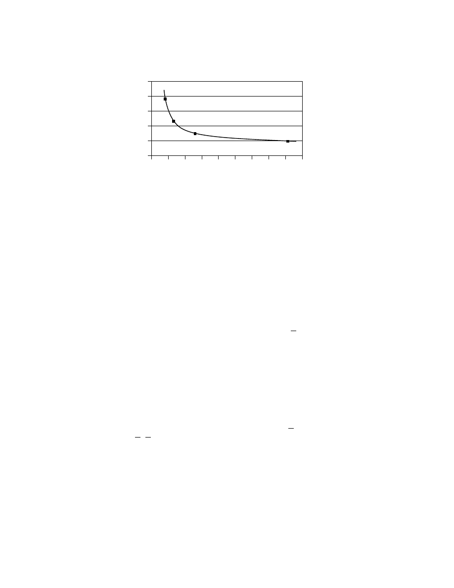
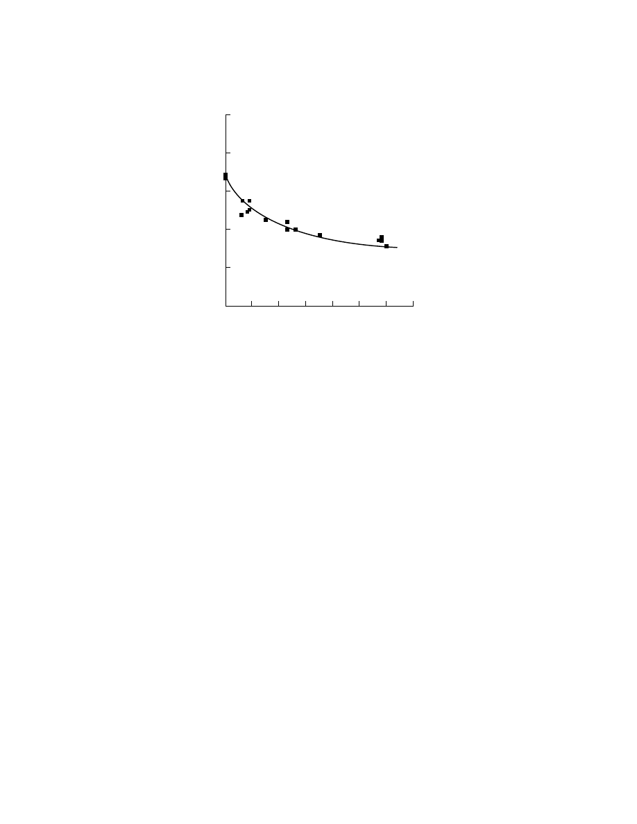
distance (ie, the chromium loading). Figure 7 shows how the activation energy of
the polymer, which reflects the degree of LCB, is affected by chromium loading on
the catalyst.
Other origins of LCB have also been identified. It has been observed that at
the typically high molecular weight used in extrusion grade resins, LCB content is
Cr
Cr
Cr
Cr
Cr
Cr
Fig. 6.
Long-chain branch formation through reincorporation of vinyl end groups.
Vol. 2
ETHYLENE POLYMERS, HDPE
395
Average Cr– Cr Separation, nm
0.0
5
15
25
10
20
30
0.2
0.4
0.6
0.8
1.0
1.2
1.4
1.6
1.8
Shear response (0.1)/ (100)
ηη
Fig. 7.
Dependence of long-chain branching (as measured by shear response) on chromium
loading.
highly dependent on the pore volume of the catalyst, even when the chromium site
density is held constant. The effect is also seen in some silica-supported Ziegler
resins of high molecular weight. When the porosity of the silica catalyst base is
very low, high levels of LCB are seen in the resin. The exact reason for this behavior
is unknown. One possible explanation is that long polymer chains entangled in
small catalyst pores (where they were formed) of catalyst fragments resist melt
flow much like true LCB, provided the relaxation time of these “knots” is longer
than the relaxation time permitted by the molding process.
More recently, extreme LCB-like behavior has also been observed from cer-
tain metallocene-derived polymers (89,90). Reincorporation of vinyl end groups
is again a possible method of origin. However, if true, it is hard to explain why
some metallocenes are so much more potent than others at creating LCB, and
why solution polymers or solution catalysts exhibit similar LCB levels to that of
samples made in slurry mode. Direct activation of polymer C H bonds by some
catalysts has also been proposed as another avenue to the formation of LCB (91).
“Chain walking” is known to happen on nickel-based catalysts (92) although it is
unknown whether this also happens on zirconium-based systems. Recently, still
another potential mechanism of LCB formation has also been advanced in this
laboratory, although not proven. It is suggested that on some catalysts two alkyl
chains may be simultaneously associated with one site through a bridging alu-
minum. If true, one chain terminated through beta-H elimination could be easily
incorporated into the other on the same site as LCB (M.P. McDaniel and M.D.
Jensen, Results from Phillips Petroleum Company Research Department).
Morphology.
The only stable local chain conformation of HDPE at low
temperature is the flat zigzag chain configuration with C C bond length of
0.154 nm, and C C C bond angle of 112
◦
(93). This local chain conformation also
prevails in the melt and solution. The principal crystalline form of linear PE is or-
thorhombic, like the linear paraffins, with theoretical density of 1.00 g/cm
3
. A sec-
ond crystalline form is pseudomonoclinic with theoretical density of 0.965 g/cm
3
.
The former is typical of most articles made of HDPE, while the latter forms during
low temperature stretching and orientation of films, and is thus always present
in HDPE film. It is stable only below 50
◦
C; annealing at 80–100
◦
C restores the
orthorhombic form.
396
ETHYLENE POLYMERS, HDPE
Vol. 2
PE Spherulite
Lamellae
a
b
c
Fig. 8.
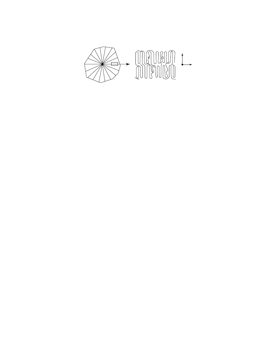
Structure of HDPE spherulite.
The principal morphological units of PE crystallizing under typical condi-
tions from the melt are spherulites, very small anisotropic spheres (ca 1–5
µm)
visible under high magnification with polarizers (Fig. 8). The spherulites form as a
result of a complex crystallization process of macromolecules. Their structural sub-
units are “rays,” thin rod-like fibrils spreading in all directions from the center to
the periphery and frequently branching, thus filling the spherulite body. The fibrils
consist of lamellae (crystallites). Spherulites are characteristic only where HDPE
crystallized slowly from the melt. In rapid crystallization, intertwined lamellae
or rod-like structures are formed (94). During crystallization, polymer chains fold
many times. When HDPE is crystallized from solution, this folding is tight, but
when crystallized from the melt, the chain packing organization is much looser
(95).
HDPE crystallizes very rapidly. Articles such as films, filaments, pipes, and
injection-molded articles exhibit some degree of molecular and crystal orientation.
This orientation develops either spontaneously during melt flow and crystalliza-
tion, or is introduced deliberately by stretching. The degree of orientation can be
measured by x-ray, polarization spectroscopy, acoustical methods, or birefringence.
When films or filaments are stretched uniaxially below the melting point, the
c-axis of the crystals is always oriented parallel to the stretching direction, as is
typical for all semicrystalline polymers. The degree of orientation increases with
the stretching ratio and can approach 100% (96). A similar orientation is developed
during the crystallization of a strongly oriented PE melt, such as during capillary
melt flow or solid-state extrusion. Under these conditions, both crystalline and
amorphous phases are nearly perfectly oriented in the flow direction (97). When
a polymer melt is slightly stretched at the outset of crystallization, a condition
typical in the production of blow-molded parts, the resulting solid films exhibit a
significant orientation of the a-axis of the crystal in the machine direction (98).
Polymer Properties
Mechanical Properties.
Polyethylene properties can be made to vary over
a wide range, by controlling the molecular weight, the molecular weight distribu-
tion, the degree of branching, the type and placement of branching, the end group
moieties, the extent of LCB, and by adding certain fillers, flow enhancers, etc. It
is no surprise then that hundreds of different grades of HDPE exist for as many
Vol. 2
ETHYLENE POLYMERS, HDPE
397
1-Butene content mol%
T
m
,°
C
150
140
130
120
110
100
0
2
4
6
8
10
12
14
Fig. 9.
Melting point of HDPE as a function of 1-butene content.
different applications, each of which require widely different properties. Such im-
portant final end-use properties include the stiffness of the polymer, the gloss or
clarity, the impact, puncture or tear resistance, chemical resistance, electrical in-
sulation properties, molding characteristics, and tensile properties, to name only
a few. Table 3 lists some of the most important polymer properties for three typical
commercial HDPE grades.
Measurements of highly crystallized HDPE samples give melting points of
133–138
◦
C. The melting point is a function of both molecular weight and of branch
content. In linear PE, the decrease in molecular weight from ca 1,000,000 to 40,000
is accompanied by a decrease in melting point from 137 to 128
◦
C. The change in
melting point with branch content is shown in Figure 9.
HDPE is a very good insulator and is therefore widely used for wire and cable
encapsulation. Polymer density and molecular weight affect electrical properties
very little. HDPE is only slightly permeable to organic compounds, both in liquid
and gas phases. Permeability to water and inorganic gases is also low.
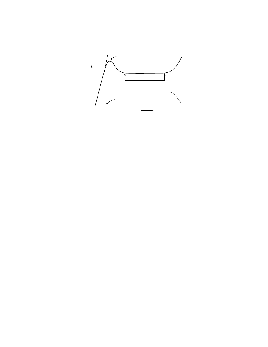
Forced elongation of an HDPE sample into a film or rod is accompanied
by structural and mechanical changes (Fig. 10) At low deformations (ca 0.5%
of sample length), spherulites elongate elastically. Further strain results in a
partial break of bridges between crystallites in lamellae, slippage of the lamellae
in rays constituting spherulites, ray splitting, and other irreversible mechanical
changes. These processes can be regarded as a succession of partial “meltings” of
the morphological features of HDPE under mechanical stress.
At some point, called the yield point, these transformations accumulate,
causing a significant change in sample appearance. A “neck” develops, which is an
area consisting of highly oriented bundles of polymer molecules. With further elon-
gation, the initial morphological structures (spherulites, rays) are disassembled
and the growth of the oriented polymer area continues. The primary mechanism
398
ETHYLENE POLYMERS, HDPE
Vol. 2
Strain
Stress
Tensile
strength
Yield
point
Limit of
elastic deformation
Elongation at
the break point
Flow at constant stress
Fig. 10.
Idealized stress–strain curve for HDPE.
of this transformation is slippage of lamellae with respect to one another and
crystallite reorientation. This process develops in the boundary layer between the
unchanged part of the sample and the neck, and continues in the neck, causing
further strain. As a result, the sample elongates at nearly constant stress until
all material in the samples becomes highly oriented. Subsequently, the oriented
structure adsorbs additional small strain at increased stress and finally beaks.
This ultimate stress is defined as the tensile strength.
Molecular weight has a large effect on this behavior. Low molecular weight
HDPE is brittle and breaks at low strain (ca 10%) without neck development.
In the range of 80,000–1,200,000, typical for commercial HDPE, the neck always
develops. The yield point of such polymers is nearly constant. However, increas-
ing molecular weight is accompanied by decreasing elongation at the breakpoint,
from ca 1200–1500% to 200–300%, and by significant increase in tensile strength,
from ca 35–40 MPa (5075–5800 psi) to ca 60 MPa (8700 psi). Finally, HDPE with
molecular weight greater than 1,500,000 does not develop a neck but elongates by
200–400%. Tensile strength of such polymers is very high, ca 60–70 MPa (8700–
10,150 psi).
Molecular weight also significantly affects impact strength. Low molecular
weight samples are brittle, but with increasing molecular weight, impact–stress
resistance can become very high.
An increase in branching reduces crystallinity and is accompanied by sig-
nificant modification of mechanical characteristics. An increase in branching is
accompanied by an increase in elongation at breakpoint and a significant drop in
tensile strength.
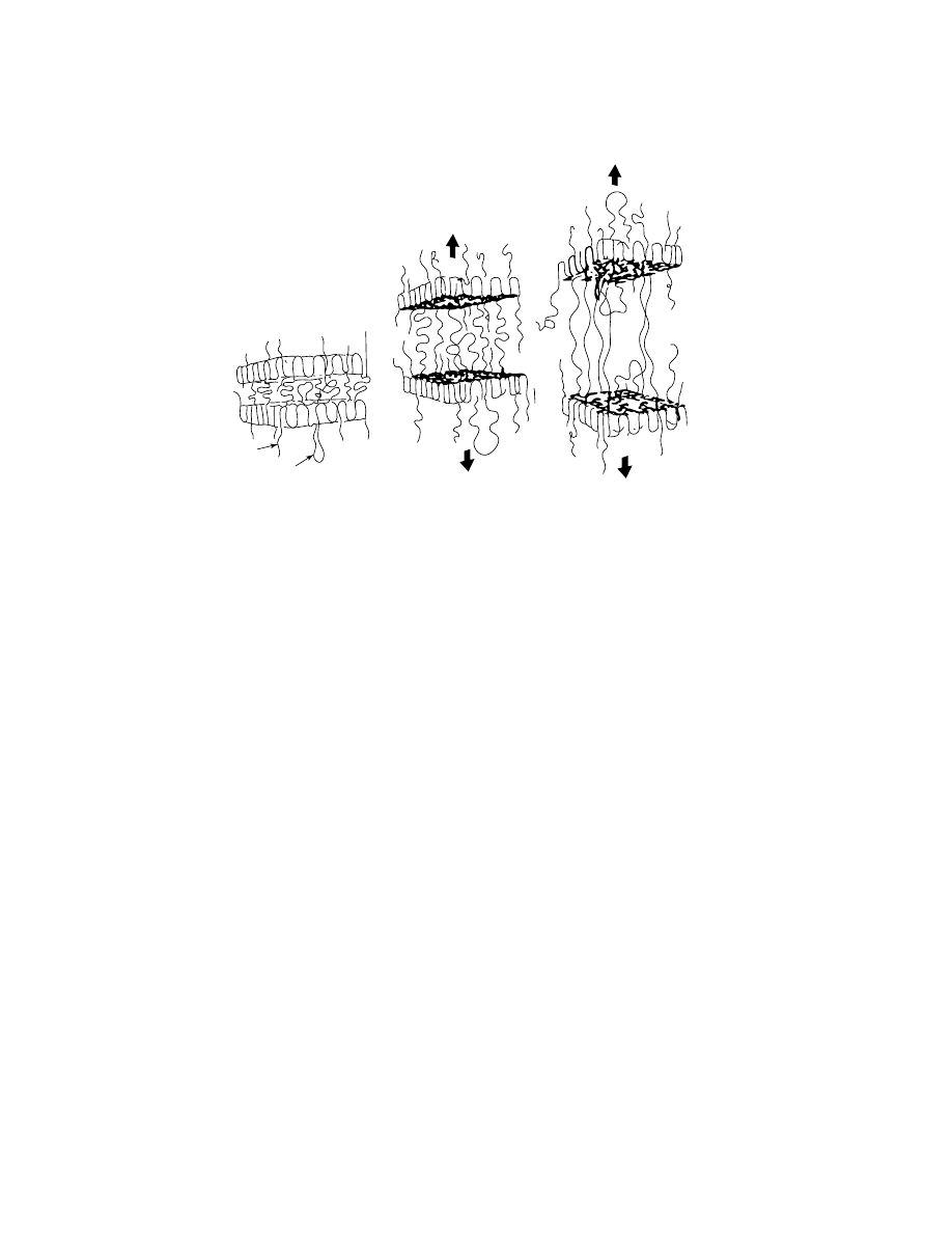
It is generally accepted that the mechanical strength of a polymer sample
is determined by the number of intercrystallite links, that is, polymer chains an-
chored in adjacent crystallites and binding them (Fig. 11). These links are the
weakest elements of the polymer structure. Special developments in processing
allow a significant increase in the number of the intercrystallite links. The tech-
nology employed is either low temperature (ca 100
◦
C) extrusion of solid HDPE at
high pressure [ca 200–300 MPa (29,000–43,500 psi)] or continuous casting of film
from a dilute solution. Such films are highly stretched (up to 40 times), usually
Vol. 2
ETHYLENE POLYMERS, HDPE
399
A
B
C
CILIA
LOOSE LOOP
TIE
MOLECULE
Fig. 11.
Role of intercrystallite links in resin failure.
transparent, and almost perfectly oriented in both phases. They exhibit ultrahigh
modulus [up to 100 GPa (1.45
× 10
7
psi)] and very high tensile strength of ca
500–600 MPa (72,500–87,000 psi).
One type of PE that has an increased number of intercrystallite links, and
thus improved physical properties, is called bimodal polymer. These polymer
grades are usually made of two components—a low molecular weight homopoly-
mer blended with a high molecular weight branched copolymer. In this combina-
tion, having branches on the longest chains selectively places these chains in the
amorphous phase, which thus increases the probability that they will function
as intercrystallite links. Much of PE research today is aimed at producing more
efficient methods of manufacturing such bimodal polymers.
Another important property that is influenced by molecular weight, by
branching, and by intercrystallite links is load-bearing ability or resistance to
creep. This property is of particular importance in applications in which the
applied stress is continuous or frequent and represents an appreciable (though
not necessarily large) fraction of the tensile strength. Even though the tensile
strength of linear PE decreases considerably as density is decreased, the load-
bearing ability of the polymer is greatly improved at densities decreasing from
0.960 to 0.950 g/cm
3
. Not only is time to failure increased greatly, but deformation
is decreased.
Chemical Resistance.
Linear PE is predominantly saturated linear hy-
drocarbon, and thus in general it exhibits low chemical reactivity. High crys-
tallinity and low permeability to most chemicals reduce the reactivity of solid
HDPE even further. HDPE is stable to alkaline solutions and solutions of salts,
including oxidizing agents such as KMnO
4
and K
2
Cr
2
O
7
. It does not react with
organic acids, HCl, or HF. Concentrated HNO
3
(ca 50%) does nitrate the polymer,
even at room temperature.

400
ETHYLENE POLYMERS, HDPE
Vol. 2
HDPE is not soluble in any known solvent at room temperature, although
several solvents (ie, xylenes) have a swelling effect. However, certain binary so-
lution mixtures including CS
2
dissolve HDPE at as low as 30–40
◦
C. Above 80
◦
C
HDPE dissolves in many aliphatic and aromatic hydrocarbons and their halogen-
substituted derivatives. Solvents most frequently used include xylenes, tetralin,
decalin, o-dichlorobenzene, 1,2,4-trichlorobenzene, and 1,2,4-trimethylbenzene.
These solvents are employed for the determination of molecular weights from
solution–viscosity data or by gpc.
An important measure of chemical resistance which is often used in house-
hold and industrial containers is environmental stress-crack resistance (ESCR).
Many variations of the test are known and used, such as ASTM D1693, Condi-
tions A and B. In these tests, the plastic part, a molded bar, a bottle, or a tube,
etc, is placed under a standardized stress usually at elevated temperature, and
exposed to a surface active agent. For example, one test uses 10% surfactant
in aqueous solution at 60
◦
C. The time needed for the sample to break is then
recorded. The surfactant is thought to aid in the relaxation and disentanglement of
chains.
Degradation.
HDPE is relatively stable to heat because of the high bond
energy of the single C C bond. However, above about 290–300
◦
C, chemical pro-
cesses in an inert medium begin to result in breakage and cross-linking of chains.
This reaction is similar to thermocracking of linear hydrocarbons. Near 500
◦
C in
an inert atmosphere, HDPE is rapidly pyrolized to a mixture of low molecular
weight alkanes, alkenes, and dienes.
Oxygen is quite aggressive toward the C H bonds of these macromolecules
at the usual melt processing temperatures (200–300
◦
C). This type of degradation
is also a combination of radical reactions, resulting in a reduction of molecular
weight, formation of oxygen-containing groups such as hydroxyl, carbonyl, and
low molecular weight by-products such as water, aldehydes, and ketones. The
initiation of oxidation can be enhanced by transition-metal impurities in the poly-
mer from catalyst residues. For this reason it is important to achieve high activity
from the catalyst, leaving only a few ppm of transition metal in the polymer. The
conditions of commercial pelletization and molding favor thermooxidative degra-
dation, and therefore oxygen is preferably excluded if possible. Protection is also
nearly always afforded by the addition of an antioxidant package as well, which
can include hindered phenols, phosphites, and other specialized agents added in
the concentration of 0.01–1.0%.
Exposure of the molded HDPE articles to sunlight and air also attacks the
polymer over time, especially at wavelengths less than 400 nm. Photooxidation
resembles thermooxidation in that it is a complex chain of radical transforma-
tions. Such exterior aging of the polymer results in development of surface cracks,
brittleness, changes in color, and a deterioration of mechanical and dielectrical
properties. Photooxidation degradation is prevented by small amounts of light
stabilizers, such as 2–4% carbon black or, for colorless articles, esters of salicylic
acid or derivatives of benzotriazole or benzophone and others in the 0.1–0.5%
range.
Chemical reactions of HDPE not involving oxidation include fluorination,
chlorination, and sulfonation. Sometimes molded articles, such as fuel tanks, are
given such a surface treatment to increase diffusional resistance.

Vol. 2
ETHYLENE POLYMERS, HDPE
401
Manufacturing Processes
Many diverse commercial technologies exist for the manufacture of HDPE, devel-
oped by many different companies worldwide. However, they can be divided into
three fundamental types: (1) solution processes, (2) slurry processes, and (3) gas-
phase processes. In recent years, hybrids and combinations of these three basic
forms have also been widely used.
Solution Processes.
The earliest commercial HDPE plants used a solu-
tion process in which the polymer dissolves in a hydrocarbon solvent as it is formed.
Cylcohexane was commonly used as solvent at 120–150
◦
C. Initially catalyst pro-
ductivity was low, but the solution process allowed a filtration or centrifugation
step in which catalyst residue could be removed. Later, as catalyst productivity
improved, this step could be omitted in some processes. Low molecular weight
polymers are made more easily in the solution process because of the lower solu-
tion viscosity. Although most of the earlier solution processes have been shut down
due to poor economics, more recent improved designs, such as those developed by
DuPont, Dow, and others, are still in production today and considered competitive
(98–104).
For example, the DuPont process is reported to operate at a temperature in
excess of 150
◦
C and a pressure of about 8 MPa (1160 psi). Residence time in the
reactor is short, on the order of 5–10 min and polymer concentration relatively
high, up to 35% for low molecular weight grades. The sensible heat of the reaction
mixture is employed to flash concentrate the solution from which the product
is recovered in a devolatilizing extruder. Terminating agents and stabilizers are
added in the extruder. Vapor from the flash step is condensed, cooled, and returned
to the reactor. Residual hydrocarbon is removed in the extrusion step and purified
for recycle to the polymerization.
The advantages of this process are a relatively small reactor and short
residence time which allows fast transition between grades and easy control
of some polymer properties. Because of the higher reactor temperature, higher
alpha-olefins can be more easily used in the solution process than in other pro-
cesses, and thus ethylene 1-octene copolymers are common from this technology.
The longer side chains derived from 1-octene (versus 1-hexene or 1-butene) are
thought to improve some resin properties. The solution process is also easily adapt-
able to multiple reactor schemes in order to tailor the molecular weight distri-
bution.
Further development of the solution polymerization concept has led to molten
PE as a medium for ethylene polymerization. Installations typically used for free-
radical ethylene polymerization at high pressure are converted to accommodate
catalytic ethylene polymerization. Stirred autoclaves operating at 30–200 MPa
(4350–29,000 psi) and 170–350
◦
C are convenient (105,106). Residence time is very
short, typically less than 1 min.
Slurry Processes.
If the hydrocarbon liquid described above is deliber-
ately chosen to be a bad solvent for PE, and the temperature is lowered so that
the polymer does not swell or melt in the hydrocarbon, the resultant process is
called slurry technology because the polymer is produced as a suspended powder.
In slurry systems the hydrocarbon non-solvent is called the diluent. Two major
types of slurry systems are widely used throughout the worldwide HDPE industry:

402
ETHYLENE POLYMERS, HDPE
Vol. 2
(1) light hydrocarbon loop reactor processes and (2) heavier hydrocarbon stirred
tank reactor processes.
Phillips Petroleum Co. originally developed the loop slurry process in the late
1950s for its chromium oxide catalyst, and Phillips has continued to develop the
loop technology up to the present on an ever larger scale. The preferred diluent is
isobutane, which was chosen to allow maximum reactor temperature without poly-
mer swelling. This was necessary because the early chromium catalysts tended
to produce lower melt index polymer (higher molecular weight) than optimum for
the new extrusion market. Higher reaction temperatures permit higher melt index
polymer to be produced. Initially, many hydrocarbon diluents were tested, and the
degree of polymer swelling caused by each diluent was found to be related to the
ratio of CH
3
to total carbons in the hydrocarbon (107). Thus, for example, pentane
was inferior to isopentane, and neopentane, which has the highest CH
3
/C ratio
of any hydrocarbon, permitted the highest reactor temperature without swelling.
However, isobutane, which permits a top reactor temperature of 113
◦
C, was con-
sidered as a close second and more economical.
The choice of light diluents and high reactor temperatures also means rela-
tively higher operating pressures. Thus a pipe-loop reactor was considered a con-
venient way to accommodate operating pressures of up to 5.5 MPa (800 psig). The
reactor is equipped with an impeller which drives a concentrated slurry of polymer
and isobutane rapidly around the jacketed loop at 5–12 m/s. Today’s loop reactors
can run up to 50% solids (by weight), typically in the temperature range of 80–
110
◦
C. Residence time is 0.5–1.5 h and conversion is high per pass (95–98%) (99).
The initial development of a slurry process for Ziegler-based catalysts did
not face the same problems as scientists at Phillips. Since Ziegler catalysts are
much more sensitive to hydrogen, molecular weight control does not rely on pre-
cise control of high reactor temperatures, as it did for the chromium oxide based
loop slurry process. Therefore, lower reactor temperatures and heavier hydrocar-
bons were possible, and there was no need to go beyond a stirred tank. Hoechst
developed the first such process, but Montedison, Mitsui, Solvay, and others have
also developed similar processes.
In the Hoechst process, for example, hexane is used as the diluent (108,109).
Hexane, ethylene, alpha-olefin, catalyst components, and hydrogen are continu-
ously fed into a stirred reactor for polymerization. The slurry is then transferred
into a smaller reactor for post-polymerization, after which the total charge is sepa-
rated by a centrifuge into a liquid stream (which is returned to the initial reactor)
and solid polymer. The wet polymer is steam-stripped from the solvent, dried, and
pelletized. The stripped hexane is purified and recycled. Although stirred tanks
are most common, loops can also be used in this fashion. In some schemes, a por-
tion of the recycle diluent from the centrifuge is returned to the reactor, and a
portion is fed to recycle purification for wax removal. This step removes some of
the lowest molecular weight polymer, which dissolves in the diluent.
Gas-Phase Processes.
Unlike solution or slurry processes, the original
gas-phase polymerization processes employed no hydrocarbon diluent. Union
Carbide introduced the first gas-phase technology in 1968, and other firms soon
developed the approach still further, such as Naphtachimie, British Petroleum,
BASF, and Amoco (110–114). In this technology, solid catalysts are used for
ethylene polymerization or its copolymerization with light comonomers in the

Vol. 2
ETHYLENE POLYMERS, HDPE
403
gas phase. The system can be agitated by mechanical devices, such as horizontal
paddles or screws, but more often by a gas stream of ethylene which fluidizes the
PE particle bed.
A typical fluidized bed reactor has a length-to-diameter ratio of ca 7 and
a disengagement zone at the top. Uniform fluidization is achieved by ethylene
flow through a distribution plate at the reactor bottom, and rapid circulation is
needed to remove heat. Conversion is about 2% per pass. Unreacted ethylene
enters the disengagement zone, separates from the entrained polymer particles,
and is filtered, cooled, compressed, and recycled. A catalyst is continuously fed
to the reactor without diluent, and polymer particles are continuously removed
from the bed through a system of valves. Reactor temperatures of 70–100
◦
C are
common, with pressure of 1.4–3.5 MPa (200–500 psig).
Polymerization of ethylene is quite exothermic (3.4
× 10
6
J/kg) and since
the heat capacity of gas is much lower than that of liquid, removal of the heat of
polymerization can be problematic compared to solution and slurry processes. This
was usually accomplished by lowering the activity of gas-phase catalysts by say
50–75% to reduce the rate of local heat generated. To compensate, the residence
time was then extended to several hours. As a result of these differences, gas-phase
processes tend to have a much larger polymer inventory in the reactor. The gas-
phase approach is also more rigid in its catalyst requirements. The kinetic profile of
a catalyst for a gas-phase process should preferably have a steady activity lasting
2–3 h. The particle size for consistent fluidization is also sometimes important,
and smaller particles are preferred for heat removal.
The fluidized bed gas-phase process offers some advantages and disadvan-
tages compared to the slurry processes. Since there is no diluent, it makes low
density resins well, without swelling. The lack of diluent also simplifies the op-
erations and equipment to some degree. On the other hand, transitions are ex-
tremely slow and there is usually a large inventory which can greatly increase
the off-specification rate during transitions. Gas-phase units are sometimes also
more sensitive to poisons in the feedstocks, and more sensitive to fouling. Once
a reactor has “logged,” cleanup can be longer and more difficult for a gas-phase
reactor.
In recent years the fluidized bed processes have been improved through the
addition of liquid hydrocarbons into the polymer bed (115,116). These evaporate,
adsorbing heat from the bed more effectively than gas alone, and are then con-
densed in the recycle stream and reused. The result of this “condensed mode” or
“super condensed mode” approach is increased production rates from the same
reactor, or greater tolerance for higher activity catalysts. Of course, it reverses
some of the benefits of pure gas phase, since it is a step back toward hydrocar-
bon diluent. Nevertheless, this innovation has greatly improved operations and
production of the gas-phase process, instilling new life into the technology.
Bimodal Reactor Technology.
In a modification of the original stirred
tank slurry process, Hoechst, Nissan, Mitsui, and others developed cascade reac-
tor systems to make bimodal resins with improved properties (67,117,118). Under
these processes, multiple reactors are aligned in series, parallel, or a combination
of series and parallel, so that a Ziegler catalyst is exposed to more than one set of
reaction conditions during its lifetime. In this way low molecular weight homopoly-
mer can be produced in combination with high molecular weight copolymer, the

404
ETHYLENE POLYMERS, HDPE
Vol. 2
so-called bimodal resin combination. This technique was originally developed to
counteract the limitation of Ziegler catalysts, which unaided, tend to make a nar-
row molecular weight distribution which is not useful for many extrusion applica-
tions. However, this type of broadening also allows the branching to be selectively
placed into the high molecular weight portion of the distribution.
In later years, other reactor arrangements have also been developed to
produce bimodal resins. Other variations include combining two loops in series
(Solvay, Fina, and others), two gas-phase reactors in series (Union Carbide), and
loop/gas phase (Borealis).
Multiple reactor processes have some advantages and disadvantages over
single reactor arrangements of similar capacity. They produce some unusual resins
that (at the time of this writing) cannot be exactly duplicated by any other means,
such as high molecular weight film resins. However, they are also more compli-
cated and more expensive to build and run, and they are much less flexible in
what can be made. Many HDPE researchers believe that new single-site catalyst
advances will eventually make bimodal reactor technology obsolete.
Commercial Applications of HDPE
Its low melting point and high chemical stability facilitate the processing of HDPE
by many conventional techniques. Some of the most common applications include
injection molding, blow molding, blown and cast film, pipe and tubing, and wire
and cable coating. Table 4 indicates the approximate current breakdown in the
United States by end use.
Injection Molding.
In this technique molten HDPE is injected into a metal
mold at 200–260
◦
C and 70–140 MPa pressure (690–1380 atm). The mold is then
cooled and opened and the solid article, which is now in the shape of the mold, is re-
moved. Usually resins with a narrow molecular weight distribution are preferred
Table 4. U.S. Usage of HDPE by Application
Market
Annual usage, 10
6
t
Market share, %
Extrusion
Film (up to 12 mil)
a
1.06
15.6
Sheet (over 12 mil)
a
0.35
5.1
Pipe and conduit, corrugated
0.30
4.3
Pipe and conduit, noncorrugated
0.58
8.5
Other extruded products
0.21
3.1
Rotomolding
0.07
1.0
Injection Molding
1.08
15.7
Blow Molding
2.23
32.5
Resellers and Compounders
0.85
12.4
All other uses
0.12
1.8
Total
6.85
100
a
Reflecting usage from the first quarter, 2000. Data from Digest of Polymer Developments,
Series I, Number 95, STR Publishing, Enfield, Conn., May, 2000.
1 mil
= 0.025% mm.
Vol. 2
ETHYLENE POLYMERS, HDPE
405
for injection-molding applications, because broader distributions are more likely
to leave orientations frozen into the articles upon cooling because of the slower
relaxation time. Such frozen orientations can lead to warpage of the article upon
cooling. For this reason most injection-molding resins are prepared from Ziegler
catalysts. Because of the narrow molecular weight distribution, which tends to
resist flow at high shear, and because of the need to completely fill sometimes
intricate molds, injection-molding resins generally have lower average molecular
weights than are needed for other applications. Injection-molding resins generally
include the melt index range of 3–80. A wide diversity of articles are made from
injection-molded HDPE including cups, pails, toys, housewares, auditorium seats
and chairs, crates, food containers, etc. (see I
NJECTION
M
OLDING
).
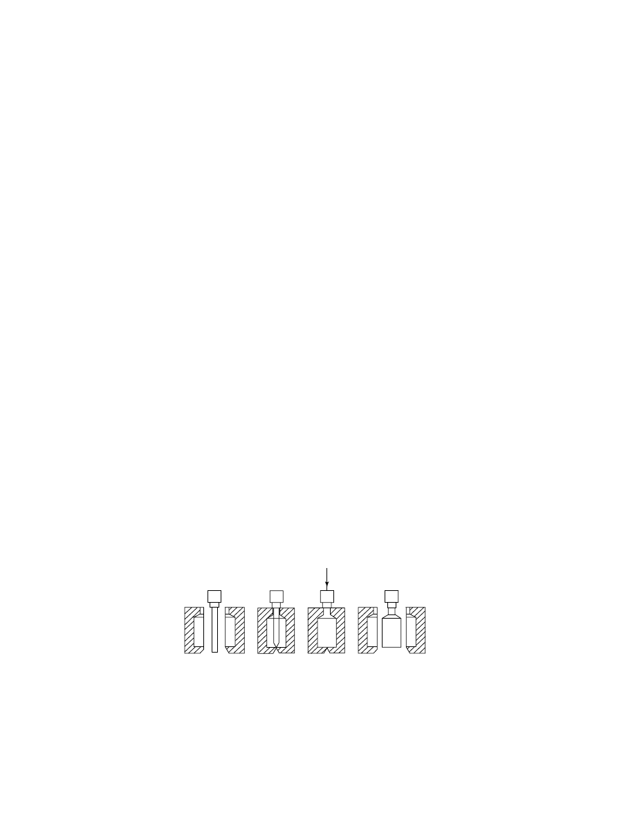
Blow Molding.
Blow molded articles account for the largest single use of
HDPE. The technique is used for rapid processing of large quantities of articles of
relatively simple configuration, such as bottles and simple containers. A molten
tube of HDPE, called a parison, is extruded through a die and then enclosed by a
doubly split metal mold (Fig. 12). The parison is blown by air pressure to conform
to the internal configuration of the mold into the formed article, much as glass is
blown into bottles. When the melt leaves the die, it swells and the parison diameter
increases, especially with HDPE of high molecular weight and at high extrusion
rates (see B
LOW
M
OLDING
).
In the initial phase of blow molding, the molten tube is extruded at high
pressure and rate through a small die gap and the tube thus formed is free-hanging
in the mold. Thus, low viscosity at high shear is preferred to enhance extrusion,
but to resist sagging in the mold, high zero-shear viscosity is preferred. Thus this
combination is achieved by using broader molecular weight distribution resins of
relatively high molecular weight (melt index 0.1–0.5). Chromium catalysts are
ideal for producing blow-molding resins.
Another important characteristic of blow-molding resins is the degree of
“parison swell” and “die swell.” The former is the extent to which the molten
tube tends to flare out during the extrusion step. An excessively high degree of
flare can cause the tube to extend beyond the mold cavity, while too little flare can
sometimes cause incomplete filling of the mold structure. Die swell is a measure
of how much the tube wall expands as it exits the die under high pressure. The
die gap must be adjusted to take die swell into account in order to produce the de-
sired wall thickness. Molders prefer to set this parameter midway and not have to
(a)
(b)
(c)
(d)
air
Fig. 12.
HDPE blow molding processing steps: (a) extrusion of parison, mold is open; (b)
mold is closed; (c) air is blown into parison; and (d) mold is opened for removal of article.
406
ETHYLENE POLYMERS, HDPE
Vol. 2
Fig. 13.
HDPE film blowing.
readjust it from one resin lot to another. The degree of swell in these resins is highly
influenced by the degree of LCB in the resin. A certain minimum level of LCB is
required for most resins. This is another reason that chromium oxide catalysts
lend themselves well to blow-molding applications. LCB content can be adjusted
easily by varying chromium loading, activation temperature, or cocatalyst level.
Blow molding is widely used to form bottles for food packaging, detergents,
oil, and other household materials, industrial drums, fuel tanks for automobiles,
toys, and a wide assortment of other articles.
Blown Film.
The impermeability, stiffness, and higher softening temper-
ature of HPDE make it useful for certain film applications (Fig. 13). A continuous
roll of blown film is produced by extrusion of HDPE melt through a die with a
circular slit of ca 0.6–1.5 mm; the diameter of the ring can typically be as large as
80–100 cm. The extruded thin-walled tube rises vertically and is filled with air,
thus expanding the tube to a certain size. Usually the ratio of the tube diameter
to the die diameter is about 4:1, allowing for the formation of a film trunk up to
4 m in diameter. The film, 0.007–0.125 mm thick, is air-cooled and rolled. Bags
can be made from the rolled hollow film tube, or it can be split into one continuous
sheet for wrapping and other uses. In coextrusion, two different types of plastic
are simultaneously extruded through a single die with two concentric circular
slits, giving a layered film. This can be done to achieve special physical properties
or permeability resistance.
Chromium-based catalysts can be used quite widely for production of HDPE
film grades but some of the best HDPE films, in terms of mechanical properties and
extrusion rates, are bimodal resins made from Ziegler catalysts passing through
two or more reaction zones. Most recently, metallocene resins have been used to
produce extremely high clarity resins, despite the high density. Applications of
HDPE films include food packaging, grocery and merchant bags, and drum liners.

Vol. 2
ETHYLENE POLYMERS, HDPE
407
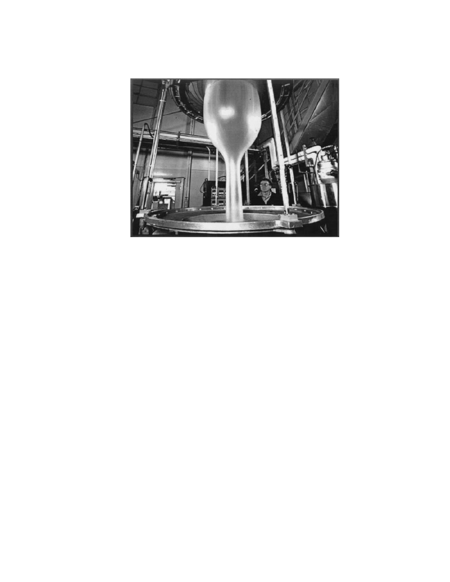
The thickest blown film made from HDPE, sometimes called sheeting, ranges
in gauge from 0.5 to 3.0 mm and is used in geomembranes. Geomembrane blowing
operations typically produce a sheet 6.9 m wide (22.5 ft), with the bubble rising
eight stories into the air, weighing 2.5 tons. Geomembrane sheeting is used to pro-
tect the environment by lining pits and covering landfills. For example, sewage
ponds and spillover sumps near oil and chemical storage tank areas are first lined
with geomembrane to prevent seepage into the groundwater. Reservoirs to hold
drinking water are also lined with geomembrane in some regions to prevent loss.
Leaching pads used in mining operations, irrigation canals, evaporation ponds,
and industrial waste lagoons are other applications of geomembrane. In this type
of service, toughness is extremely valued to avoid penetration by rocks, tree roots,
etc. Thus, high molecular weight and a significant amount of branching is pre-
ferred in the polymer. The blowing operation favors resins with high melt strength,
which is imparted by high levels of LCB. Chromium catalysts are commonly used
for this type of blown film.
Thermoforming.
Thermoforming is a process in which the resin is ex-
truded into flat sheets of perhaps 2–13 mm after which that sheet is softened
by heat and then stamped or pulled by vacuum into a large mold. Thermo-
formed sheet is widely used for trays, pans, for lining the beds of pickup trucks
or other vehicles, for flooring, and a wide variety of other articles. Thermo-
forming resins typically require stiffness, toughness, and good melt strength,
all of which are achieved from chromium oxide catalysts at 0.05–0.2 melt
index.
Pipe and Tubing.
Pipes (diameter
>1 cm) and tubing (diameter <1 cm)
are produced by passing HDPE melt through a die with a circular channel, form-
ing a thick tube. Immediately after leaving the die, the molten tube enters a
vacuum calibrator, where it is forced against sizing rings and cooled. Extrusion
and drawdown (ratio of the cross-sectional area of the die opening to the tube wall)
are adjusted with the help of mechanical pulling devices. For pipe manufacture,
die openings are large, resistance to polymer flow is low, and drawdown does not
exceed 1.1. Pipes with diameter ca 1.5 m are made commercially.
HDPE pipe is used in low pressure applications for transporting potable
water, gas, acids, liquid hydrocarbons, oils, salt water, and other chemicals and
solvents. Long-term load bearing, or “creep,” tests are essential to determine the
life of PE pipe under pressure. HDPE pipe withstands pressures in short-term
burst tests that are several times greater than long-term burst pressures because
of the creep phenomenon. Broad molecular weight distribution resin, as obtained
from chromium oxide catalysts, are ideal for most pipe applications. The intro-
duction of superior, bimodal type, pipe resins in recent years has extended HDPE
pipe applications.
Wire and Cable Insulation.
Excellent electrical properties and moisture
resistance make linear PE ideal for wire and cable coatings. Use includes power,
communications, and control applications. Continuous coatings can be extruded
directly onto wire at high speed, followed by cooling in a bath. The lubricity and
high abrasion resistance of the coating aid in conduit installations. Copolymers
of 0.935–0.945 g/cm
3
density and ca 1 melt index are commonly used because of
the good balance of toughness, ESCR, and extrudability. Polymers of medium-to-
broad molecular weight distribution are preferred because of high coating speeds

408
ETHYLENE POLYMERS, HDPE
Vol. 2
and good surface finish. Addition of about 2.5% small particle carbon black greatly
increases weather resistance.
Filament.
In the production of monofilament, extruded strands are
quenched, reheated, then pulled to draw ratios of 10:1. The tensile strength of
finished filament is 345–690 MPa (50,000–100,000 psi) due to the high degree of
orientation. Cord and rope are used in sporting goods and utility purposes. Larger
PE rope is used in marine applications where it has a clear advantage over ny-
lon, since HDPE floats and does not adsorb water. Ribbon yarn, made from split
film, finds applications in carpet backing, some fabrics, bags, and in binding of
multiwire cable together. A large market for these products is especially found in
Asia and South America. Owing to its chemical inertness, linear PE is used for
monofilament gauze for tissue reinforcement in surgery. Ziegler resins are partic-
ularly well suited to these applications, although chromium oxide derived resins
are also common.
Rotomolding.
Larger items, such as tote boxes, fuel tanks, and water stor-
age tanks are often made by a rotational molding operation. Usually HDPE pow-
der or pellets are introduced into a mold cavity which is then heated and rotated
evenly. As the polymer melts, it coats the inside surface of the mold uniformly. The
mold is then cooled while still under rotation to prevent sagging or other imper-
fections. Sometimes organic peroxide is added so that upon heating the plastic,
a cross-linking reaction takes place in which the molecular weight and viscosity
of the plastic dramatically increases. The mold is then separated and the article
removed. Tanks up to 37.8 M
3
(10,000 gal) are made in this way. Rotomolding ap-
plications require good flow under zero-shear conditions. Narrow molecular weight
distribution resins, as provided by Ziegler or metallocene catalysts, are preferred
for rotomolding applications.
Health and Safety of HDPE
HPDE is generally inert and lacking in any toxicity, which accounts for its
widespread use in food packaging. It is also used in prosthetic devices, in surgery,
hip or knee joint replacements, etc.
HDPE can present some health hazard during its combustion, pyrolysis, or
during thermocutting, when smoke, fumes or toxic decomposition products can be
formed. Irritation of the skin, eyes, and mucous membranes of the nose and throat
are possible. In some cases this irritation has been traced to traces of acrolein
or formaldehyde from thermooxidative decomposition. However, other large-scale
fire testing of foamed PE under actual conditions did not reveal significant acrolein
formation and demonstrated that PE presents no worse hazard than cellulosic
materials. Still other studies indicate that maximum evolution of irritants occurs
from smoldering combustion at 300–400
◦
C.
BIBLIOGRAPHY
“Ethylene Polymers” in EPST 1st ed., Vol. 6, pp. 275–454; “Ethylene Polymers, High Density
Polyethylene” in EPSE 2nd ed., Vol. 6, pp. 454–490, by D. L. Beach, Chevron Chemical Co.,
and Y. V. Kissin, Mobil Chemical Co.

Vol. 2
ETHYLENE POLYMERS, HDPE
409
1. E. Hinderman, Dissertation, Zurich, 1897.
2. H. von Fechman, Ber. 31, 2643 (1898).
3. E. Bamberger and F. Techirner, Ber. 33, 955 (1900).
4. J. Hertzig and R. Schonbach, Monatsh. Chem. 33, 677 (1912).
5. H. Meerwein and W. Burneleit, Ber. 618, 1840 (1928).
6. W. Werle, Dissertation, Marburg, 1938.
7. Phillips Petroleum Co., unpublished data, 1981; H. R. Sailors and J. P. Hogan, J.
Macromol. Sci. Chem. A 15(7), 1377–1402 (1981).
8. Hoberg, and K. Ziegler, Brennstoff-Chemie 39, 302 (1958).
9. R. A. V. Raff and E. Lyle, in R. A. V. Raff and K. W. Doak eds.,
High Polymers, Vol. XX, Part I, Wiley-Interscience, New York, 1965, p. 8.
10. H. Pichler, Brennstoff-Chemie 19, 226 (1938).
11. H. Pichler and H. Buffleb, Brennstoff-Chemie 21(24), 285 (1940).
12. J. C. Swallows, in A. Renfraw and P. Morgan, eds., Polythene, 2nd ed., Interscience
Publishers, New York, 1960, pp. 1–10.
13. Brit. Pat. 471590 (allowed Sept. 6, 1937), E. W. Facett and co-workers (to ICI).
14. J. J. Fox, and A. E. Martin, Trans. Faraday Soc. 36, 897 (1940).
15. U.S. Pat. 2816883 (Filed 1951, Issued 1957), A. W. Larcher and D. C. Pease (to E. I.
du Pont de Nemours & Co., Inc.).
16. U.S. Pat. 2692257 (Filed Apr. 28, 1951, Issued 1954), A. Zietz (to Standard Oil of
Indiana).
17. Belg. Pat. 530617 (Filed Jan. 24, 1955 and in the U.S. on Jan. 27, 1953 as S.N. 333,576),
J. P. Hogan and R. L. Banks (to Phillips Petroleum Co.); Aust. Pat. Appl. 864/54 (Filed
Aug. 6, 1954).
18. Ger. Pat. 973626 (Filed Nov. 17, 1953 and issued Apr. 14, 1960), K. Ziegler and co-
workers (to K. Ziegler); U.S. Pat. 3257332 (Filed Nov. 15, 1954 and issued June 21,
1966).
19. Chemistry in the Economy, American Chemical Society, Washington, D.C., 1973,
p. 71.
20. E. L. D’Ouville, in Ref. 12, p. 35.
21. J. P. Hogan, in G. Ham., ed., High Polymers, Vol. XVII, Wiley-Interscience, New York,
1964, p. 111.
22. A. Clark and co-workers, Ind. Eng. Chem. 48, 1152 (1956).
23. R. V. Jones and P. J. Boeke, Ind. Eng. Chem. 48, 1155 (1956).
24. D. C. Smith, Ind. Eng. Chem. 48, 1161 (1956).
25. M. P. McDaniel, Adv. Catal. 33, 47–98 (1985).
26. R. Merryfield, M. P. McDaniel, and G. Parks, J. Catal. 77, 348 (1982).
27. J. P. Hogan, J. Polym. Sci., Part A-1 8, 2637 (1970).
28. Inorg. Nucl. Chem. 4, 393 (1968); H. L. Krauss and H. Stach, Z. Anorg. Chem. 366,
280 (1969).
29. M. P. McDaniel and M. E. Grayson, J. Mol. Catal. 65(1/2), 139–144 (1991).
30. M. P. McDaniel and S. J. Martin. J. Phys. Chem. 95, 3289 (1991).
31. C. Groeneveld and co-workers, J. Catal. 83, 346 (1983).
32. H. L. Krauss and E. Hums, Z. Naturforsch., B: Anorg. Chem., Org. Chem. 34b, 1628
(1979);
H. L. Krauss and E. Hums, Z. Naturforsch., B: Anorg. Chem., Org. Chem.
35b(7), 848 (1980);
H. L. Krauss and E. Hums, Z. Naturforsch., B: Anorg. Chem.,
Org. Chem. 38b(11), 1412 (1983).
33. H. L. Krauss, in Symposium on the Mechanisms of Hydrocarbon Reactions, Slofok
Hungary, 1973.
34. J. A. N. Anjjou and S. L. Scott, J. Am. Chem. Soc. 122(37), 8968, (2000).
35. J. A. N. Anjjou, S. L. Scott, and V. Paquet, J. Am. Chem. Soc. 120(2), 415, (1998).
36. G. Ghiotti and co-workers, J. Chem. Soc. Chem. Commun., Com. 801, 1032 (1979).

410
ETHYLENE POLYMERS, HDPE
Vol. 2
37. G. Ghiotti and co-workers, J. Catal. 80, 249 (1983).
38. A. Zecchina and co-workers, J. Phys. Chem. 79(10), 972 (1975).
39. A. Zecchina and co-workers, J. Phys. Chem. 79(10), 978 (1975).
40. E. Garrone and co-workers, J. Phys. Chem. 79(10), 985 (1975).
41. M. P. McDaniel and M. M. Johnson, J. Catal. 101, 446–457 (1986).
42. E. A. Benham, P. D. Smith and M. P. McDaniel, Polym. Eng. Sci. (SPE) 28(22), 1469–
1472 (1988).
43. U.S. Pat. 3157712 (Nov. 1967), D. L. Walker and E. L. Czenkusch (to Phillips Petroleum
Co.).
44. F. J. Karol and R. N. Johnson, J. Polym. Sci., Polym. Chem. Ed. 13, 1607 (1975).
45. F. J. Karol, G. L. Brown, and J. M. Davison, J. Polym. Sci., Polym. Chem. Ed. 11, 413
(1973).
46. F. J. Karol and co-workers, J. Polym. Sci., Part A-1 10, 2621 (1972).
47. F. J. Karol and co-workers, J. Catal. 60, 68 (1979).
48. U.S. Pat. 3840508 (Oct. 1974), D. G. H. Ballard and co-workers (to Imperial Chemical
Industries).
49. P. D. Smith and M. P. McDaniel, J. Polym. Sci., Polym. Chem. Ed. 27, 2695 (1989).
50. P. D. Smith and M. P. McDaniel, J. Polym. Sci., Polym. Chem. Ed. 28, 3587 (1990).
51. M. P. McDaniel, C. H. Leigh, and S. M. Wharry, J. Catal. 120, 170 (1989).
52. S. M. Wharry, S. J. Martin, and M. P. McDaniel, J. Catal. 115, 463 (1989).
53. M. P. Mcaniel, C. H. Leigh, and S. M. Wharry, J. Catal. 120, 170 (1989).
54. M. P. McDaniel, M. B. Welch, and M. J. Dreiling, J. Catal. 82, 118 (1983).
55. T. T. P. Cheung and co-workers, J. Catal. 102, 10–20 (1986).
56. F. J. Karol, Catal. Rev. Sci. Eng. 26(3/4), 557 (1984).
57. G. Fink, R. Mulhaupt, and H. H. Brintzinger, Ziegler Catalysis: Recent Scientific
Innovations and Technological Improvements, Springer-Verlag, New York, 1995.
58. J. Boor Jr., Ziegler–Natta Catalysts and Polymerizations, Academic Press, Inc.,
New York, 1979.
59. Y. V. Kissin, Macromol. Symp. 89, 113 (1995).
60. Brit. Pat. 1286867 (1969), A. Mayr and co-workers (to Montedison).
61. W. A. Hewett, J. Polym. Sci. B 3, 855 (1965).
62. G. A. Short, and E. C. Shokal, J. Polym. Sci. B 3, 859 (1965).
63. J. L. Martin and co-workers, Inorg. Chem. 23, 4589 (1984).
64. J. L. Martin and co-workers, Inorg. Chem. 24, 2997 (1985).
65. H. L. Hsieh, M. P. McDaniel, J. L. Martin, P. D. Smith, and D. R. Fahey, in R.
B. Seymour and T. Cheng, eds., Advances in Polyolefins, Plenum Publishing Corp.,
New York, 1987.
66. L. L. Bohm, J. Berthold, R. Franke, W. Strobel, and U. Wolfmier, in T. Keii and K.
Soga, ed., Proc. Int Symp., Tokyo, Japan, 4–6 July, 1985,
Proc. Int Symp., Elsevier,
Amsterdam, 1985, p. 29.
67. L. L. Bohm, H. F. Enderle, and M. Fleissner, Plast. Rubber Compos. Process. Appl.
27(1), 25 (1998).
68. W. Breslow, Justus Liebigs Ann. Chem. 463 (1975).
69. W. Kaminsky, Angew. Chem. 88, 689 (1976).
70. M. Aulbach and F. Kuber, Chem. Unserer Zeit 28, 197 (1994).
71. P. C. Mohring and N. J. Coville, J. Organomet. Chem. 479, 1 (1994).
72. K. B. Sinclair and R. B. Wilson, Chem. Ind. (London) 857 (1994); W. Kaminsky, Catal.
Today 20, 257 (1994).
73. H. H. Brintzinger and co-workers, Angew. Chem. Int. Ed. Engl. 34, 1143 (1995).
74. U.S. Pat. 5919983 (March, 1997), R. K. Rosen and D. D. VanderLende (to The Dow
Chemical Company).
75. U.S. Pat. 6107230 (Aug. 2000), M. P. McDaniel (to Phillips Petroleum Co.).

Vol. 2
ETHYLENE POLYMERS, HDPE
411
76. B. L. Small, M. Brookhart, and A. M. A. Benett, J. Am Chem. Soc. 120, 4049 (1998).
77. Angew. Chem. 111, 448 (1999); G. J. P. Britovsek, V. C. Gibson, and D. F. Wass, Angew.
Chem. Int. Ed. Engl. 38, 428 (1999).
78. U.S. Pat. 5891963 (Apr. 6, 1999), M. S. Brookhart and co-workers (to E. I. du Pont de
Nemours & Co., Inc.).
79. G. V. Schultz, Z. Phys. Chem., Abt. B. 30, 379 (1935); P. J. Flory, J. Am. Chem. Soc.
58, 1877 (1936).
80. A. Clark and G. C. Bailey, J. Catal. 2, 230,241 (1963).
81. M. P. McDaniel and M. M. Johnson, Macromolecules 20, 773 (1987).
82. U.S. Pat. 4966951, (1990), E. A. Benham, M. P. McDaniel, and F. W. Bailey (to Phillips
Petroleum Co.); U.S. Pat. 4818800 (1989), M. P. McDaniel and J. N. Short (to Phillips
Petroleum Co.);
U.S. Pat. 4364854 (1982), M. P. McDaniel and M. M. Johnson (to
Phillips Petroleum Co.).
83. M. P. McDaniel, J. Polym. Sci. Polym. Chem. Ed. 19, 1967 (1981).
84. W. C. Conner and co-workers, Stud. Surf. Sci. Catal. 75B, 1827–1830 (1993).
85. J. Janzen and R. H. Colby, J. Mol. Struct. 569, 485–486 (1999).
86. A. M. Sukhadia, in Soc. Plastics Eng. ANTEC Conf. Proc., Atlanta, Ga., 1998, p. 160.
87. A. M. Sukhadia, in Soc. Plastics Eng. ANTEC Conf. Proc., Atlanta, Ga., 1998, p. 1157.
88. J. P. Hogan, Applied Industrial Catalysis, Vol. 1, Academic Press, Inc., Orlando, Fla.,
1983, Chapt. “6”.
89. WJ. Wang and co-workers, Macromolecules 31, 8677 (1998).
90. A. Malmberg and co-workers, Macromolecules 32, 6687, (1999).
91. M. K. Reinking, G. Orf, and D. McFaddin, J. Polym. Sci., Part A: Polym. Chem. 36,
2889 (1998).
92. V. M. Mohring and G. Fink, Angew. Chem. Int. Ed. Engl. 24(11), 1001 (1985).
93. H. V. Boenig, Polyolefins: Structure and Properties, Elsevier, Amsterdam, 1966.
94. L. Mandelkern and co-workers, J. Polym. Sci Polym. Lett. Ed. 19, 435 (1981).
95. M. Stamm, J. Polym. Sci. Polym. Phys. Ed. 20, 235 (1982).
96. R. S. Stain, in B. Ke, ed., Methods of Polymer Characterization, Wiley-Intescience,
New York, 1964.
97. A. E. Zachariades and R. S. Porter, J. Macromol. Sci. Phys. B 19, 377 (1981).
98. T. Nagasawa, T. Matsumura, and T. Hochino, Appl. Polym. Symp. 20, 295 (1973).
99. J. N. Short, in R. P. Quirk, ed., Transition Metal Catalyzed Polymerizations: Alkenes
and Dienes, Harwood Academic Publishers, New York, 1983, p. 651.
100. J. P. Forsman, Hydrocarbon Process 51, 132 (Nov. 1972).
101. U.S. Pat. 3644325 (Feb. 22, 1972), R. F. Roberts Jr. (to The Dow Chemical Company).
102. U.S. Pat. 4209603 (June 24, 1980), J. J. M. A. Van de Leemput (to Stamicarbon B.V.).
103. U.S. Pat. 4067822 (Jan. 10, 1978), D. E. Gessell, G. L. Dighton, and L. D. Valenzuela-
Bernal (to The Dow Chemical Company).
104. Plast. Technol. 26(2), 39 (1980).
105. J. P. Machon, R. Hermant, and J. P. Houzeaux, J. Polym. Sci. Polym. Symp. 52, 107
(1975).
106. J. P. Machon, in Ref. 99, p. 639.
107. J. P. Hogan, D. D. Norwood, and C. A. Ayres, Applied Polymer Symposium Vol. 36:
Commodity and Engineering Plastics, Wiley-Interscience, New York, 1982.
108. B. Diedrich, Polym. Prepr. 16(1), 316 (1975).
109. H. Kreuter and B. Diedrich, Chem. Eng. 81(16), 62 (1974).
110. U.S. Pat. 4011382 (1977), I. J. Levine and F. J. Karol (to Union Carbide Corp.).
111. U.S. Pat. 4003712 (1977), A. R. Miller (to Union Carbide Corp.).
112. U.S. Pat. 3965083 (1976), J. L. Jezl, E. F. Peters, and J. W. Shepard (to Standard Oil
Co.).
113. U.S. Pat. 3922322 (1975), R. Dormenval, L. Havas, and P. Mangin (to Napthachimie).

412
ETHYLENE POLYMERS, HDPE
Vol. 2
114. D. M. Rasmussen, Chem. Eng. 79, 104 (1972).
115. U.S. Pat. 4255542 (1981), G. L. Brown, D. F. Warner, and J. H. Byon (to Union Carbide
Corp.).
116. U.S. Pat. 5352749 (Oct. 1994), M. L. DeChellis and J. R. Griffin (to Exxon Chemicals).
117. U.S. Pat. 4307209 (Dec. 22, 1981), Y. Morita and N. Kashiwa (to Mitsui Chemical).
118. U.S. Pat. 4357448 (Nov. 2, 1982), K. Tsubaki and co-workers (to Nissan Chemical).
E
LIZABETH
B
ENHAM
M
AX
M
C
D
ANIEL
Chevron Phillips Chemical Company
Wyszukiwarka
Podobne podstrony:
Ethylene Polymers, LLDPE
Ethylene Polymers, LDPE
Ethylene Polymers, Chlorosulfonated
Ethylene Polymers, LLDPE
Ethylene Oxide Polymers
Perfluorinated Polymers, Perfluorinated Ethylene—Propylene Copolymers
Degradable Polymers and Plastics in Landfill Sites
Development of Carbon Nanotubes and Polymer Composites Therefrom
Polymer Processing With Supercritical Fluids V Goodship, E Ogur (Rapra, 2004) Ww
Inorganic Polymers
Propylene Polymers
Fundamentals of Polymer Chemist Nieznany
więcej podobnych podstron