
KONICA BUSINESS TECHNOLOGIES, INC.
SERVICE MANUAL
FIELD SERVICE
7115/7118


i
CONTENTS
DIS/REASSEMBLY, ADJUSTMENT
1. SAFETY INFORMATION ................................................................................. D-1
1-1. LASER SAFETY ...................................................................................... D-1
1-2. INTERNAL LASER RADIATION .............................................................. D-1
1-3. LASER SAFETY LABEL .......................................................................... D-4
1-4. LASER CAUTION LABEL ........................................................................ D-4
1-5. PRECAUTIONS FOR HANDLING THE LASER EQUIPMENT ............... D-4
2. SERVICE INSTRUCTIONS ............................................................................. D-5
2-1. IDENTIFICATION OF FUSES AND CIRCUIT BREAKERS .................... D-5
2-2. PARTS WHICH MUST NOT BE TOUCHED ........................................... D-6
(1)
Red Painted Screws ........................................................................ D-6
(2)
Variable Resistors on Board ............................................................ D-6
3. DISASSEMBLY/REASSEMBLY ...................................................................... D-7
3-1. DOORS, COVERS, AND EXTERIOR PARTS: IDENTIFICATION
AND REMOVAL PROCEDURES ............................................................ D-7
3-2. REMOVAL OF CIRCUIT BOARDS AND OTHER ELECTRICAL
COMPONENTS ....................................................................................... D-9
(1)
Removal of the Master Board .......................................................... D-10
(2)
Removal of the Control Board ......................................................... D-11
(3)
Removal of the High Voltage Unit ................................................... D-11
(4)
Removal of the DC Power Supply ................................................... D-13
3-3. MAINTENANCE SCHEDULE .................................................................. D-16
3-4. PAPER TAKE-UP/TRANSPORT SECTION ............................................ D-18
(1)
Removal of the Paper Separator Roll Assy and
Paper Take-Up Roll ......................................................................... D-18
(2)
Cleaning of the Paper Separator Roll .............................................. D-18
(3)
Cleaning of the Paper Take-Up Roll ................................................ D-18
(4)
Cleaning of the Right and Left Synchronizing Rollers ..................... D-19
(5)
Removal of the Cleaning Pad .......................................................... D-19
(6)
Cleaning of the Cleaning Pad .......................................................... D-20
(7)
Cleaning of the Bypass Transport Roller ......................................... D-20
3-5. OPTICAL SECTION ................................................................................ D-21
(1)
Cleaning of the Original Glass and ADF Glass ............................... D-21
(2)
Cleaning of Mirrors .......................................................................... D-21
(3)
Cleaning of the Lens ........................................................................ D-21
(4)
Cleaning of the CCD Sensor ........................................................... D-22
(5)
Cleaning of the Scanner Rails/Bushings ......................................... D-22
(6)
Removal of the CCD Unit ................................................................ D-23
(7)
Removal of the Scanner, Exposure Lamp, and Inverter Board ....... D-23
(8)
Removal of the Scanner Drive Cables ............................................ D-25
(9)
Winding of the Scanner Drive Cables .............................................. D-27
3-6. PH ............................................................................................................ D-29
(1)
Removal of the PH Unit ................................................................... D-29
(2)
Cleaning of the PH Window ............................................................. D-29

ii
3-7. Imaging Unit (IU) ...................................................................................... D-30
(1)
Removal of the IU ............................................................................ D-30
(2)
Disassembly of the IU ...................................................................... D-30
(3)
Application of Toner ......................................................................... D-34
(4)
Replacement of the ATDC Sensor .................................................. D-35
3-8. IMAGE TRANSFER SECTION ................................................................ D-36
(1)
Removal of the Image Transfer Roller Assy .................................... D-36
(2)
Cleaning of the Pre-Image Transfer Lower Guide Plate .................. D-36
(3)
Cleaning of the Charge Neutralizing Plate ...................................... D-36
3-9. FUSING SECTION .................................................................................. D-37
(1)
Removal of the Fusing Unit ............................................................. D-37
(2)
Disassembly of the Fusing Unit ....................................................... D-37
3-10.MULTIPLE BYPASS (MT-102): OPTION ................................................ D-42
(1)
Removal of the Separator Roll Assy ................................................ D-42
(2)
Removal of the Paper Take-Up Roll ................................................ D-42
(3)
Cleaning of the Separator Roll/Paper Take-Up Roll ........................ D-45
(4)
Cleaning of the Paper Take-Up Roll ................................................ D-45
3-11.JOB TRAY (IT-102): OPTION ................................................................. D-46
(1)
Removal of the Main Board ............................................................. D-46
(2)
Paper Detecting Board .................................................................... D-48
3-12.SHIFTING UNIT (IS-101): OPTION ......................................................... D-49
(1)
Removal of the Main Board ............................................................. D-49
4. ADJUSTMENT ................................................................................................. D-51
4-1. ADJUSTMENT JIGS AND TOOLS USED ............................................... D-51
4-2. TIMING BELT TENSION ADJUSTMENT ................................................ D-51
4-3. ACCESSING THE FUNCTION, TECH. REP. CHOICE, AND
ADJUST MODE ....................................................................................... D-52
(1)
Function Mode ................................................................................. D-52
(2)
Tech. Rep. Choice Mode ................................................................. D-52
(3)
Adjust Mode ..................................................................................... D-52
4-4. ELECTRICAL/IMAGE ADJUSTMENT ..................................................... D-53
(1)
Edge Erase Adjustment (Leading, Trailing, and Top/Bottom
Edges) ............................................................................................. D-53
(2)
Loop Length Adjustment (1st and 2nd Trays, Bypass Tray) ........... D-54
(3)
Printer CD Registration Adjustment ................................................. D-55
(4)
Printer FD Registration Adjustment ................................................. D-56
(5)
Scanner CD Registration Adjustment .............................................. D-57
(6)
Scanner FD Registration Adjustment .............................................. D-58
(7)
Scanner CD Zoom Adjustment ........................................................ D-59
(8)
Scanner FD Zoom Adjustment ........................................................ D-60
(9)
ATDC Sensor Automatic Adjustment (F8) ....................................... D-61
(10) 2nd Mirrors Carriage Distortion Adjustment .................................... D-61
(11) Manual Bypass Registration Adjustment ......................................... D-62
(12) Multiple Bypass Registration Adjustment (MT-102): Option ............ D-63
4-5. OTHER ADJUSTMENTS ......................................................................... D-64
(1)
Adjustment of the Position of the Scanner and 2nd/3rd Mirrors
Carriage ........................................................................................... D-64

iii
(2)
CCD Unit Position Adjustment ......................................................... D-65
(3)
Adjustment of the Gap between the Doctor Blade and Sleeve
Roller (Db Adjustment) .................................................................... D-66
4-6. MISCELLANEOUS .................................................................................. D-68
(1)
Remounting the EEPROM (U29) ..................................................... D-68
(2)
Installation of the Plug-In Counter Socket (Option) ......................... D-69
(3)
Installation of the Total Counter (Option) ......................................... D-70
SWITCHES ON PWBs, TECH. REP. SETTINGS
1. CONTROL PANEL KEYS AND TOUCH PANEL ............................................. S-1
1-1. Control Panel Keys .................................................................................. S-1
2. UTILITY MODE ................................................................................................ S-4
2-1. Settings in the Utility Mode ...................................................................... S-4
2-2. Utility Mode Setting Procedure ................................................................ S-4
(1)
User’s Choice Mode (Display: U-1) ................................................. S-4
(2)
Drum Dehumidify Mode (Display: U-2) ............................................ S-9
(3)
Toner Replenisher Mode (Display: U-3) .......................................... S-9
(4)
Custom Size Input Mode (Display: U-4) .......................................... S-9
(5)
Administrator Mode (Display: U-5) .................................................. S-10
3. TECH.REP.MODE ........................................................................................... S-13
3-1. Tech.Rep.Mode Menu Function Tree ...................................................... S-13
3-2. Tech.Rep.Mode Function Setting Procedure ........................................... S-14
3-3. Setting in the Tech.Rep.Mode ................................................................. S-15
(1)
Control Panel LED Check (Display: - - 0) ........................................ S-15
(2)
Function (Display: - - 1) ................................................................... S-15
(3)
Tech.Rep.Choice (Display: - - 2) ..................................................... S-16
(4)
Counter Mode (Display: - - 3) .......................................................... S-18
(5)
ATDC Sensor Output (Display: - - 4) ............................................... S-21
(6)
Level History (Display: - - 5) ............................................................ S-21
(7)
ROM Version (Display: - - 6) ........................................................... S-21
(8)
Administrator No. Input (Display: - - 7) ............................................ S-22
(9)
Change Fixed Zoom (Display: - - 8) ................................................ S-22
(10) Marketing Area Setting (Display: - - 9) ............................................ S-22
(11) Memory Clear (Display: - 10) ........................................................... S-23
(12) Total Clear (Display: - 11) ................................................................ S-23
(13) ADF Document Passage Test (Display: - 12) .................................. S-23
(14) ADF Original Glass Check (Display: - 13) ....................................... S-24
(15) Scanner Move Check (Display: - 14) ............................................... S-24
(16) Serial No. Display (Display: - 20) ..................................................... S-24
4. SECURITY MODE ........................................................................................... S-25
4-1. Settings in the Security Mode .................................................................. S-25
4-2. Security Mode Setting Procedure ............................................................ S-25
4-3. Setting in the Security Mode .................................................................... S-26
5. ADJUST MODE ............................................................................................... S-27
5-1. Settings in the Adjust Mode ..................................................................... S-27
5-2. Adjust Mode Setting Procedure ............................................................... S-27
5-3. Setting in the Adjust Mode ....................................................................... S-28

iv
TROUBLESHOOTING
1. INTRODUCTION ............................................................................................. T-1
1-1. Reading the Text ..................................................................................... T-1
2. PAPER TRANSPORT FAILURE ..................................................................... T-2
2-1. Paper Misfeed Detection ......................................................................... T-2
(1)
Outline ............................................................................................. T-2
2-2. Paper Misfeed .......................................................................................... T-2
2-3. Misfeed Detection Sensor Layout ............................................................ T-4
2-4. Types of Misfeed Detection and Detection Timings ................................ T-6
3. MISFEED TROUBLESHOOTING PROCEDURES ......................................... T-7
3-1. Misfeed at Copier Paper Take-Up J01 and Misfeed at
Bypass Tray J06 ...................................................................................... T-7
3-2. Misfeed at Paper Feed Cabinet Paper Take-Up and
Transport Section J02, J03, J04, J05, J1 (PF-121) ................................. T-11
3-3. Misfeed at PC Drum J2 ............................................................................ T-13
3-4. Misfeed at Fusing Unit J3 ........................................................................ T-16
4. MALFUNCTION ............................................................................................... T-18
4-1. Detection Timing by Malfunction Code .................................................... T-18
4-2. Resetting Procedure by Malfunction Code .............................................. T-22
4-3. Troubleshooting Procedures by Malfunction Code .................................. T-23
(1)
C0000: Main Motor malfunction ....................................................... T-23
(2)
C0045: Fusing Cooling Fan Motor malfunction ............................... T-24
(3)
C004E: Power Supply Cooling Fan Motor malfunction ................... T-25
(4)
C0070: Toner Replenishing Motor malfunction ............................... T-26
(5)
C0210: Abnormal image transfer voltage ........................................ T-27
(6)
C0500: Warm-up failure
C0510: Abnormally low fusing temperature
C0520: Abnormally high fusing temperature ................................... T-28
(7)
C0650: Faulty Scanner Home Position Sensor ............................... T-30
(8)
C0B60: Bin Switching Motor malfunction ........................................ T-31
(9)
C0B80 Shift Motor malfunction ........................................................ T-33
(10) C0F32: Faulty ATDC Sensor
C0F33: Improperly adjusted ATDC Sensor ..................................... T-34
(11) C1038: Engine connection failure .................................................... T-35
(12) C1200: Faulty ASIC/memory ........................................................... T-35
(13) C1300: Polygon Motor malfunction (startup failure,
Lock signal failure, faulty Lock signal)
C13F0: Faulty HSYNC .................................................................... T-36
(14) C1468: Faulty EEPROM .................................................................. T-37
(15) C14A3: IR fluorescent lamp fault ..................................................... T-38
(16) The copier does not turn ON. .......................................................... T-40
5. IMAGE FAILURE ............................................................................................. T-42
5-1. Image Failure Troubleshooting ................................................................ T-42
5-2. Initial Checks ........................................................................................... T-42
5-3. Image Failure Samples ............................................................................ T-44
5-4. Troubleshooting Procedures by Image Failure ........................................ T-45
(1)
Blank copy ....................................................................................... T-45

v
(2)
Black copy ....................................................................................... T-46
(3)
Low image density ........................................................................... T-47
(4)
Foggy background or rough image .................................................. T-49
(5)
Black streaks or bands .................................................................... T-51
(6)
Black spots ...................................................................................... T-52
(7)
Blank streaks or bands .................................................................... T-53
(8)
Void areas ....................................................................................... T-54
(9)
Smear on back ................................................................................ T-55
(10) Uneven image density ..................................................................... T-56
(11) Gradation reproduction failure ......................................................... T-58
(12) Periodically uneven image ............................................................... T-59
6. OTHER ERROR CODES ................................................................................ T-60
WIRING/CIRCUIT DIAGRAMS
SERVICE/ADJUSTMENT ITEM LIST
ELECTRICAL PARTS LAYOUT
CONNECTOR LAYOUT
WIRING DIAGRAMS (1-2)
CIRCUIT DIAGRAM (1-2)
CIRCUIT DIAGRAM PWB-A (1-3)
DF-217 WIRING DIAGRAM
DF-217 CIRCUIT DAIGRAM PWB
PF-121 WIRING DIAGRAM
PF-121 CIRCUIT DIAGRAM PWB

vi

SAFETY PRECAUTIONS
Installation Environment
Safety considerations usually are directed toward
machine design and the possibility of human error. In
addition, the environment in which a machine is oper-
ated must not be overlooked as a potential safety
hazard.
Most electrical equipment is safe when installed in a
normal environment. However, if the environment is
different from what most people consider to be nor-
mal, it is conceivable that the combination of the
machine and the room air could present a hazardous
combination. This is because heat (such as from
fusing units) and electrical arcs (which can occur
inside switches) have the ability to ignite flammable
substances, including air.
When installing a machine, check to see if there
is anything nearby which suggests that a poten-
tial hazard might exist. For example, a laboratory
might use organic compounds which, when they
evaporate, make the room air volatile. Potentially dan-
gerous conditions might be seen or smelled. The
presence of substances such as cleaners, paint thin-
ners, gasoline, alcohol, solvents, explosives, or simi-
lar items should be cause for concern.
If conditions such as these exist, take appropriate
action, such as one of the following suggestions.
•
Determine that the environment is controlled
(such as through the use of an exhaust hood) so
that an offending substance or its fumes cannot
reach the machine.
•
Remove the offending substance.
•
Install the machine in a different location.
The specific remedy will vary from site to site, but the
principles remain the same. To avoid the risk of injury
or damage, be alert for changes in the environment
when performing subsequent service on any ma-
chine, and take appropriate action.
Unauthorized Modifications
Konica equipment has gained a reputation for being
reliable products. This has been attained by a combi-
nation of outstanding design and a knowledgeable
service force.
The design of the equipment is extremely important.
It is the design process that determines tolerances
and safety margins for mechanical, electrical, and
electronic aspects. It is not reasonable to expect
individuals not involved in product engineering to
know what effect may be caused by altering any
aspect of the machine’s design. Such changes have
the potential of degrading product performance and
reducing safety margins.
For these reasons, installation of any modification not
specifically authorized by Konica Business Machines
U.S.A., Inc., is strictly prohibited.
The following list of prohibited actions is not all-inclu-
sive, but demonstrates the intent of this policy.
•
Using an extension cord or any unauthorized
power cord adapter.
•
Installing any fuse whose rating and physical size
differs from that originally installed.
•
Using wire, paper clips, solder, etc., to replace or
eliminate any fuse (including temperature fuses).
•
Removing (except for replacement) any air filter.
•
Defeating the operation of relays by any means
(such as wedging paper between contacts).
•
Causing the machine to operate in a fashion other
than as it was designed.
•
Making any change which might have a chance
of defeating built-in safety features.
•
Using any unspecified replacement parts.
General Safety Guidelines
This equipment has been examined in accordance
with the laws pertaining to various product safety
regulations prior to leaving the manufacturing facility
to protect the operators and service personnel from
injury. However, as with any operating device, compo-
nents will break down through the wear-and-tear of
everyday use, as will additional safety discrepancies
be discovered. For this reason, it is important that the
technician periodically performs safety checks on the
equipment to maintain optimum reliability and safety.
The following checks, not all-inclusive, should be
made during each service call:
CAUTION: Avoid injury. Ensure that the equipment is
disconnected from its power source before continu-
ing.
•
Look for sharp edges, burrs, and damage on all
external covers and copier frame.
•
Inspect all cover hinges for wear (loose or bro-
ken).
•
Inspect cables for wear, frays, or pinched areas.
SAFETY PRECAUTIONS
vii

•
Ensure that the power cord insulation is not dam-
aged (no exposed electrical conductors).
•
Ensure that the power cord is properly mounted
to the frame by cord clamps.
•
Check the continuity from the round lug (GND) of
the power cord to the frame of the copier -- ensure
continuity. An improperly grounded machine can
cause an electrically-charged machine frame.
Safeguards During Service Calls
Confirm that all screws, parts, and wiring which are
removed during maintenance are installed in their
original positions.
•
When disconnecting connectors, do not pull the
wiring, particularly on AC line wiring and high
voltage parts.
•
Do not route the power cord where it is likely to
be stepped on or crushed.
•
Carefully remove all toner and dirt adhering to any
electrical units or electrodes.
•
After part replacement or repair work, route the
wiring in such a way that it does not contact any
burrs or sharp edges.
•
Do not make any adjustments outside of the
specified range.
Applying Isopropyl Alcohol
Care should be exercised when using isopropyl alco-
hol, due to its flammability. When using alcohol to
clean parts, observe the following precautions:
•
Remove power from the equipment.
•
Use alcohol in small quantities to avoid spillage
or puddling. Any spillage should be cleaned up
with rags and disposed of properly.
•
Be sure that there is adequate ventilation.
•
Allow a surface which has been in contact with
alcohol to dry for a few minutes to ensure that the
alcohol has evaporated completely before apply-
ing power or installing covers.
Summary
It is the responsibility of every technician to use pro-
fessional skills when servicing Konica products. There
are no short cuts to high-quality service. Each piece
of equipment must be thoroughly inspected with re-
spect to safety considerations as part of every routine
service call. The operability of the copier, and more
importantly, the safety of those who operate or service
the equipment, are directly dependent upon the con-
scientious effort of each and every technician.
Remember...when performing service calls, use good
judgment (have a watchful eye) to identify safety
hazards or potential safety hazards that may be pre-
sent, and correct these problem areas as they are
identified -- the safety of those who operate the equip-
ment as well as those who service the copier depend
on it!
SAFETY PRECAUTIONS
viii
P-1
1.
SAFETY PRECAUTIONS FOR INSPECTION AND
SERVICE
• When performing inspection and service procedures, observe the following precautions
to prevent accidents and ensure utmost safety.
✽
Depending on the model, some of the precautions given in the following do not apply.
• Different markings are used to denote specific meanings as detailed below.
Indicates a potentially hazardous situation which, if not avoided,
could result in death or serious injury.
Indicates a potentially hazardous situation which, if not avoided,
may result in minor or moderate injury. It may also be used to
alert against unsafe practices.
• The following graphic symbols are used to give instructions that need to be observed.
Used to call the service technician’s attention to what is graphically represented
inside the marking (including a warning).
Used to prohibit the service technician’s from doing what is graphically repre-
sented inside the marking.
Used to instruct the service technician’s to do what is graphically represented
inside the marking.
1-1.
Warning
1. Always observe precautions.
2. Before starting the procedures, be sure to unplug the power cord.
WARNING
CAUTION
WARNING
• Parts requiring special attention in this product will include a label containing the
mark shown on the left plus precautionary notes. Be sure to observe the pre-
cautions.
• Be sure to observe the “Safety Information” given in the Operator’s Manual.
• This product contains a high-voltage unit and a circuit with a large current
capacity that may cause an electric shock or burn.
• The product also contains parts that can jerk suddenly and cause injury.
• If this product uses a laser, laser beam leakage may cause eye damage or
blindness.
P-2
3. Do not throw toner or the toner bottle into a fir.
4. Use the specified parts.
5. Handle the power cord with care and never use a multiple outlet.
6. Be careful with the high-voltage parts.
7. Do not work with wet hands.
8. Do not touch a high-temperature part.
9. Maintain a grounded connection at all times. (This item may not apply in the USA.)
10. Do not remodel the product.
• Do not throw toner or the toner bottle (Imaging Cartridge) into a fire. Toner
expelled from the fire may cause burns.
• For replacement parts, always use the genuine parts specified in the manufac-
turer’s parts manual. Installing a wrong or unauthorized part could cause dielec-
tric breakdown, overload, or undermine safety devices resulting in possible
electric shock or fire.
• Replace a blown electrical fuse or thermal fuse with its corresponding genuine
part specified in the manufacturer’s parts manual. Installing a fuse of a different
make or rating could lead to a possible fire. If a thermal fuse blows frequently,
the temperature control system may have a problem and action must be taken
to eliminate the cause of the problem.
• Do not break, crush or otherwise damage the power cord. Placing a heavy
object on the power cord, or pulling or bending it may damage it, resulting in a
possible fire or electric shock.
• Do not use a multiple outlet to which any other appliance or machine is con-
nected.
• Be sure the power outlet meets or exceeds the specified capacity.
• A part marked with the symbol shown on the left carries a high voltage. Touch-
ing it could result in an electric shock or burn. Be sure to unplug the power cord
before servicing this part or the parts near it.
• Do not unplug or plug in the power cord, or perform any kind of service or
inspection with wet hands. Doing so could result in an electric shock.
• A part marked with the symbol shown on the left and other parts such as the
exposure lamp and fusing roller can be very hot while the machine is energized.
Touching them may result in a burn.
• Wait until these parts have cooled down before replacing them or any surround-
ing parts.
• Be sure to connect the ground wire to the ground terminal even when perform-
ing an inspection or repair. Without proper grounding, electrical leakage could
result in an electric shock or fire.
• Never connect the ground wire to a gas pipe, water pipe, telephone ground wire,
or a lightning conductor.
• Modifying this product in a manner not authorized by the manufacturer may
result in a fire or electric shock. If this product uses a laser, laser beam leakage
may cause eye damage or blindness.
P-3
11. Restore all parts and harnesses to their original positions.
1-2.
Caution
1. Precautions for Service Jobs.
2. Precautions for Servicing with Covers and Parts Removed.
• To promote safety and prevent product damage, make sure the harnesses are
returned to their original positions and properly secured in their clamps and sad-
dles in order to avoid hot parts, high-voltage parts, sharp edges, or being
crushed.
• To promote safety, make sure that all tubing and other insulating materials are
returned to their original positions. Make sure that floating components mounted
on the circuit boards are at their correct distance and position off the boards.
CAUTION
• A toothed washer and spring washer, if used originally, must be reinstalled.
Omitting them may result in contact failure which could cause an electric shock
or fire.
• When reassembling parts, make sure that the correct screws (size, type) are
used in the correct places. Using the wrong screw could lead to stripped
threads, poorly secured parts, poor insulating or grounding, and result in a mal-
function, electric shock or injury.
• Take great care to avoid personal injury from possible burrs and sharp edges on
the parts, frames and chassis of the product.
• When moving the product or removing an option, use care not to injure your
back or allow your hands to be caught in mechanisms.
• Wherever feasible, keep all parts and covers mounted when energizing the
product.
• If energizing the product with a cover removed is absolutely unavoidable, do not
touch any exposed live parts and use care not to allow your clothing to be
caught in the moving parts. Never leave a product in this condition unattended.
• Never place disassembled parts or a container of liquid on the product. Parts
falling into, or the liquid spilling inside, the mechanism could result in an electric
shock or fire.
• Never use a flammable spray near the product. This could result in a fire.
• Make sure the power cord is unplugged before removing or installing circuit
boards or plugging in or unplugging connectors.
• Always use the interlock switch actuating jig to actuate an interlock switch when
a cover is opened or removed. The use of folded paper or some other object
may damage the interlock switch mechanism, possibly resulting in an electric
shock, injury or blindness.

P-4
3. Precautions for the Working Environment.
4. Precautions for Handling Batteries. (Lithium, Nickel-Cadmium, etc.)
5. Precautions for the Laser Beam. (Only for Products Employing a Laser)
6. Precautions for storage the toner or imaging cartridge.
1-3.
Other Precautions
• When handling circuit boards, observe the “HANDLING of PWBs”.
• The PC Drum is a very delicate component. Observe the precautions given in “HAN-
DLING OF THE PC DRUM” because mishandling may result in serious image problems.
• Note that replacement of a circuit board may call for readjustments or resetting of partic-
ular items, or software installation.
• The product must be placed on a flat, level surface that is stable and secure.
• Never place this product or its parts on an unsteady or tilting workbench when
servicing.
• Provide good ventilation at regular intervals if a service job must be done in a
confined space for a long period of time.
• Avoid dusty locations and places exposed to oil or steam.
• Avoid working positions that may block the ventilation ports of the product.
• Replace a rundown battery with the same type as specified in the manufac-
turer’s parts manual.
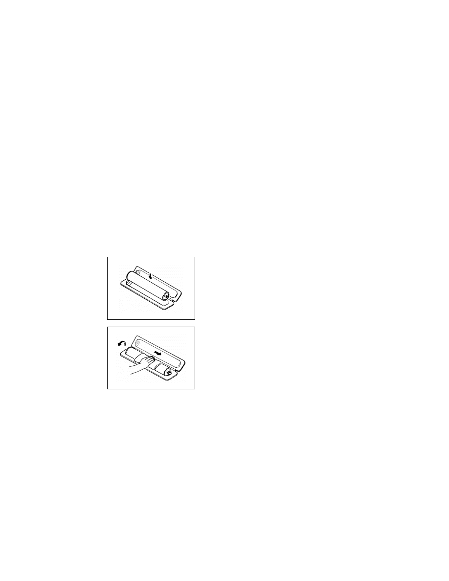
• Before installing a new battery, make sure of the correct polarity of the installa-
tion or the battery could burst.
• Dispose of used batteries according to the local regulations. Never dispose of
them at the user’s premises or attempt to try to discharge one.
• Removing the cover marked with the caution label could lead to possible expo-
sure to the laser beam, resulting in eye damage or blindness. Be sure to unplug
the power cord before removing this cover.
• If removing this cover while the power is ON is unavoidable, be sure to wear pro-
tective laser goggles that meet specifications.
• Make sure that no one enters the room when the machine is in this condition.
• When handling the laser unit, observe the “Precautions for Handling Laser
Equipment.”
• Be sure to keep the toner or imaging cartridge out of the reach of children. Lick-
ing the imaging cartridge or ingesting its contents is harmful to your health.

P-5
1-4.
Used Batteries Precautions
ALL Areas
CAUTION
Danger of explosion if battery is incorrectly replaced.
Replace only with the same or equivalent type recommended by the manufacturer.
Dispose of used batteries according to the manufacturer’s instructions.
Germany
VORSICHT!
Explosionsgefahr bei unsachgemäßem Austausch der Batterie.
Ersatz nur durch denselben oder einen vom Hersteller empfohlenen gleichwertigen Typ.
Entsorgung gebrauchter Batterien nach Angaben des Herstellers.
France
ATTENTION
Il y a danger d’explosion s’il y a remplacement incorrect de la batterie.
Remplacer uniquement avec une batterie du même type ou d’un type équivalent recom-
mandé par le constructeur.
Mettre au rebut les batteries usagées conformément aux instructions du fabricant.
Denmark
ADVARSEL!
Lithiumbatteri - Eksplosionsfare ved fejlagtig håndtering.
Udskiftning må kun ske med batteri af samme fabrikat og type.
Levér det brugte batteri tilbage til leverandøren.
Finland, Sweden
VAROlTUS
Paristo voi räjähtää, jos se on virheellisesti asennettu.
Vaihda paristo ainoastaan laitevalmistajan suosittelemaan tyyppiin.
Hävitä käytetty paristo valmistajan ohjeiden mukaisesti.
VARNING
Explosionsfara vid felaktigt batteribyte.
Använd samma batterityp eller en ekvivalent typ som rekommenderas av apparat-
tillverkaren.
Kassera använt batteri enligt fabrikantens instruktion.
Norway
ADVARSEL
Eksplosjonsfare ved feilaktig skifte av batteri.
Benytt samme batteritype eller en tilsvarende type anbefalt av apparatfabrikanten.
Brukte batterier kasseres i henhold til fabrikantens instruksjoner.

P-6
1-5.
Precautions for Service
• When performing inspection and service procedures, observe the following precautions
to prevent mishandling of the machine and its parts.
✽
Depending on the model, some of the precautions given in the following do not apply.
1. Precautions Before Service
• When the user is using a word processor or personal computer from a wall outlet of the
same line, take necessary steps to prevent the circuit breaker from opening due to over-
loads.
• Never disturb the LAN by breaking or making a network connection, altering termination,
installing or removing networking hardware or software, or shutting down networked
devices without the knowledge and express permission of the network administrator or
the shop supervisor.
2. How to Use this Book
< DIS/REASSEMBLY, ADJUSTMENT >
• To reassemble the product, reverse the order of disassembly unless otherwise specified.
< TROUBLESHOOTING >
• If a component on a PWB or any other functional unit including a motor is defective, the
text only instructs you to replace the whole PWB or functional unit and does not give trou-
bleshooting procedures applicable within the defective unit.
• All troubleshooting procedures contained herein assume that there are no breaks in the
harnesses and cords and all connectors are plugged into the right positions.
• The procedures preclude possible malfunctions due to noise and other external causes.
3. Precautions for Service
• Check the area surrounding the service site for any signs of damage, wear or need of
repair.
• Keep all disassembled parts in good order and keep tools under control so that none will
be lost or damaged.
• After completing a service job, perform a safety check. Make sure that all parts, wiring
and screws are returned to their original positions.
• Do not pull out the toner hopper while the toner bottle is turning. This could result in a
damaged motor or locking mechanism.
• If the product is to be run with the front door open, make sure that the toner hopper is in
the locked position.
• Do not use an air gun or vacuum cleaner for cleaning the ATDC Sensor and other sen-
sors, as they can cause electrostatic destruction. Use a blower brush and cloth. If a unit
containing these sensors is to be cleaned, first remove the sensors from the unit.

P-7
4. Precautions for Dis/Reassembly
• Be sure to unplug the copier from the outlet before attempting to service the copier.
• The basic rule is not to operate the copier anytime during disassembly. If it is absolutely
necessary to run the copier with its covers removed, use care not to allow your clothing to
be caught in revolving parts such as the timing belt and gears.
• Before attempting to replace parts and unplug connectors, make sure that the power
cord of the copier has been unplugged from the wall outlet.
• Be sure to use the Interlock Switch Actuating Jig whenever it is necessary to actuate the
Interlock Switch with the covers left open or removed.
• While the product is energized, do not unplug or plug connectors into the circuit boards
or harnesses.
• Never use flammable sprays near the copier.
• A used battery should be disposed of according to the local regulations and never be dis-
carded casually or left unattended at the user’s premises.
• When reassembling parts, make sure that the correct screws (size, type) and toothed
washer are used in the correct places.
5. Precautions for Circuit Inspection
• Never create a closed circuit across connector pins except those specified in the text and
on the printed circuit.
• When creating a closed circuit and measuring a voltage across connector pins specified
in the text, be sure to use the GND wire.

P-8
6. Handling of PWBs
< During Transportation/Storage >
• During transportation or when in storage, new P.W. Boards must not be indiscriminately
removed from their protective conductive bags.
• Do not store or place P.W. Boards in a location exposed to direct sunlight and high tem-
perature.
• When it becomes absolutely necessary to remove a Board from its conductive bag or
case, always place it on its conductive mat in an area as free as possible from static elec-
tricity.
• Do not touch the pins of the ICs with your bare hands.
• Protect the PWBs from any external force so that they are not bent or damaged.
< During Inspection/Replacement >
• Avoid checking the IC directly with a multimeter; use connectors on the Board.
• Never create a closed circuit across IC pins with a metal tool.
• Before unplugging connectors from the P.W. Boards, make sure that the power cord has
been unplugged from the outlet.
• When removing a Board from its conductive bag or conductive case, do not touch the
pins of the ICs or the printed pattern. Place it in position by holding only the edges of the
Board.
• When touching the PWB, wear a wrist strap and connect its cord to a securely grounded
place whenever possible. If you cannot wear a wrist strap, touch a metal part to dis-
charge static electricity before touching the PWB.
• Note that replacement of a PWB may call for readjustments or resetting of particular
items.
7. Handling of Other Parts
• The magnet roller generates a strong magnetic field. Do not bring it near a watch, floppy
disk, magnetic card, or CRT tube.
P-9
8. Handling of the PC Drum
✽
Only for Products Not Employing an Imaging Cartridge.
< During Transportation/Storage >
• Use the specified carton whenever moving or storing the PC Drum.
• The storage temperature is in the range between –20°C and +40°C.
• In summer, avoid leaving the PC Drum in a car for a long time.
< Handling >
• Ensure that the correct PC Drum is used.
• Whenever the PC Drum has been removed from the copier, store it in its carton or protect
it with a Drum Cloth.
• The PC Drum exhibits greatest light fatigue after being exposed to strong light over an
extended period of time. Never, therefore, expose it to direct sunlight.
• Use care not to contaminate the surface of the PC Drum with oil-base solvent, finger-
prints, and other foreign matter.
• Do not scratch the surface of the PC Drum.
• Do not apply chemicals to the surface of the PC Drum.
• Do not attempt to wipe clean the surface of the PC Drum.
If, however, the surface is contaminated with fingerprints, clean it using the following proce-
dure.
A. Place the PC Drum into one half of its carton.
1076D001
B. Gently wipe the residual toner off the surface of the
PC Drum with a dry, Dust-Free Cotton Pad.
• Turn the PC Drum so that the area of its surface on
which the line of toner left by the Cleaning Blade is
present is facing straight up. Wipe the surface in one
continuous movement from the rear edge of the PC
Drum to the front edge and off the surface of the PC
Drum.
• Turn the PC Drum slightly and wipe the newly
exposed surface area with a CLEAN face of the
Dust-Free Cotton Pad. Repeat this procedure until
the entire surface of the PC Drum has been thor-
oughly cleaned.
✽
At this time, always use a CLEAN face of the dry
Dust-Free Cotton Pad until no toner is evident on the
face of the Pad after wiping.
1076D002

P-10
NOTES
• Even when the PC Drum is only locally dirtied, wipe the entire surface.
• Do not expose the PC Drum to direct sunlight. Clean it as quickly as possible even under
interior illumination.
• If dirt remains after cleaning, repeat the entire procedure from the beginning one more
time.
9. Handling of the Imaging Cartridge
✽
Only for Products Employing an Imaging Cartridge.
< During Transportation/Storage >
• The storage temperature is in the range between –20°C and +40°C.
• In summer, avoid leaving the Imaging Cartridge in a car for a long time.
< Handling >
• Store the Imaging Cartridge in a place that is not exposed to direct sunlight.
< Precautionary Information on the PC Drum Inside the Imaging Cartridge >
• Use care not to contaminate the surface of the PC Drum with oil-base solvent, finger-
prints, and other foreign matter.
• Do not scratch the surface of the PC Drum.
• Do not attempt to wipe clean the surface of the PC Drum.
C. Soak a small amount of either ethyl alcohol or iso-
propyl alcohol into a clean, unused Dust-Free Cot-
ton Pad which has been folded over into quarters.
Now, wipe the surface of the PC Drum in one con-
tinuous movement from its rear edge to its front
edge and off its surface one to two times.
✽
Never move the Pad back and forth.
1076D003
D. Using the SAME face of the Pad, repeat the proce-
dure explained in the latter half of step 3 until the
entire surface of the PC Drum has been wiped.
Always OVERLAP the areas when wiping. Two
complete turns of the PC Drum would be appropri-
ate for cleaning.
1076D004

DIS/REASSEMBLY,
ADJUSTMENT

D-1
1.
SAFETY INFORMATION
1-1.
LASER SAFETY
• This is a digital machine certified as a class 1 laser product. There is no possibility of
danger from a laser, provided the machine is serviced according to the instruction in this
manual.
1-2.
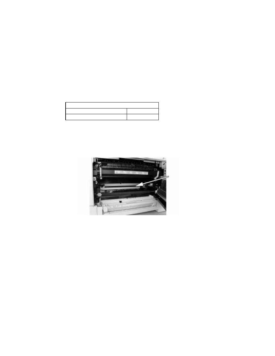
INTERNAL LASER RADIATION
*:Laser Aperture of the Print Head Unit
• This product employs a Class 3b laser diode that emits an invisible laser beam. The laser
diode and the scanning polygon mirror are incorporated in the print head unit.
• The print head unit is NOT A FIELD SERVICE ITEM. Therefore, the print head unit
should not be opened under any circumstances.
Semiconductor laser
Maximum average radiation power(*)
26.4 µW
Wavelength
770-795 nm
Laser Aperture of
the Print Head Unit
This figure Shows the view inside the Right Door
with the Imaging Unit removed.

D-2
the U.S.A., Canada
(CDRH Regulation)
• This machine is certified as a Class I Laser product under Radiation Performance Stan-
dard according to the Food, Drug and Cosmetic Act of 1990. Compliance is mandatory
for Laser products marketed in the United States and is reported to the Center for
Devices and Radiological Health (CDRH) of the U.S. Food and Drug Administration of
the U.S. Department of Health and Human Services (DHHS). This means that the device
does not produce hazardous laser radiation.
• The label shown to page D-4 indicates compliance with the CDRH regulations and must
be attached to laser products marketed in the United States.
All Areas
Denmark
CAUTION
Use of controls, adjustments or performance of procedures other than those specified in
this manual may result in hazardous radiation exposure.
Semiconductor laser
Maximum power of the laser diode
5 mW
Wavelength
770-795 nm
CAUTION
Use of controls, adjustments or performance of procedures other than those specified in
this manual may result in hazardous radiation exposure.
Semiconductor laser
Maximum power of the laser diode
5 mW
Wavelength
770-795 nm
ADVARSEL
Usynlig Laserstråling ved åbning, når sikkerhedsafbrydere er ude af funktion. Undgå
udsættelse for stråling. Klasse 1 laser produkt der opfylder IEC60825 sikkerheds kravene.
Halvlederlaser
Laserdiodens højeste styrke
5 mW
Bølgelængden
770-795 nm

D-3
Finland, Sweden
Norway
VARO!
Avattaessa ja suojalukitus ohitettaessa olet alttiina näkymättömälle lasersäteilylle. Älä
katso säteeseen.
LOUKAN 1 LASERLAITE
KLASS 1 LASER APPARAT
VAROITUS!
Laitteen Käyttäminen muulla kuin tässä käyttöohjeessa mainitulla tavalla saattaa altistaa
käyttäjän turvallisuusluokan 1 ylittävälle näkymättömälle lasersäteilylle.
Puolijohdelaser
Laserdiodin suurin teho
5 mW
Aallonpituus
770-795 nm
VARNING!
Om apparaten används på annat sätt än i denna bruksanvisning specificerats, kan använ-
daren utsättas för osynlig laserstrålning, som överskrider gränsen för laserklass 1.
Halvledarlaser
Den maximala effekten för laserdioden
5 mW
Våglängden
770-795 nm
VARNING!
Osynlig laserstrålning när denna del är öppnad och spärren är urkopplad. Betrakta ej
strålen.
ADVERSEL
Dersom apparatet brukes på annen måte enn spesifisert i denne bruksanvisning, kan
brukeren utsettes for unsynlig laserstråling som overskrider grensen for laser klass 1.
Halvleder laser
Maksimal effekt till laserdiode
5 mW
Bølgelengde
770-795 nm
D-4
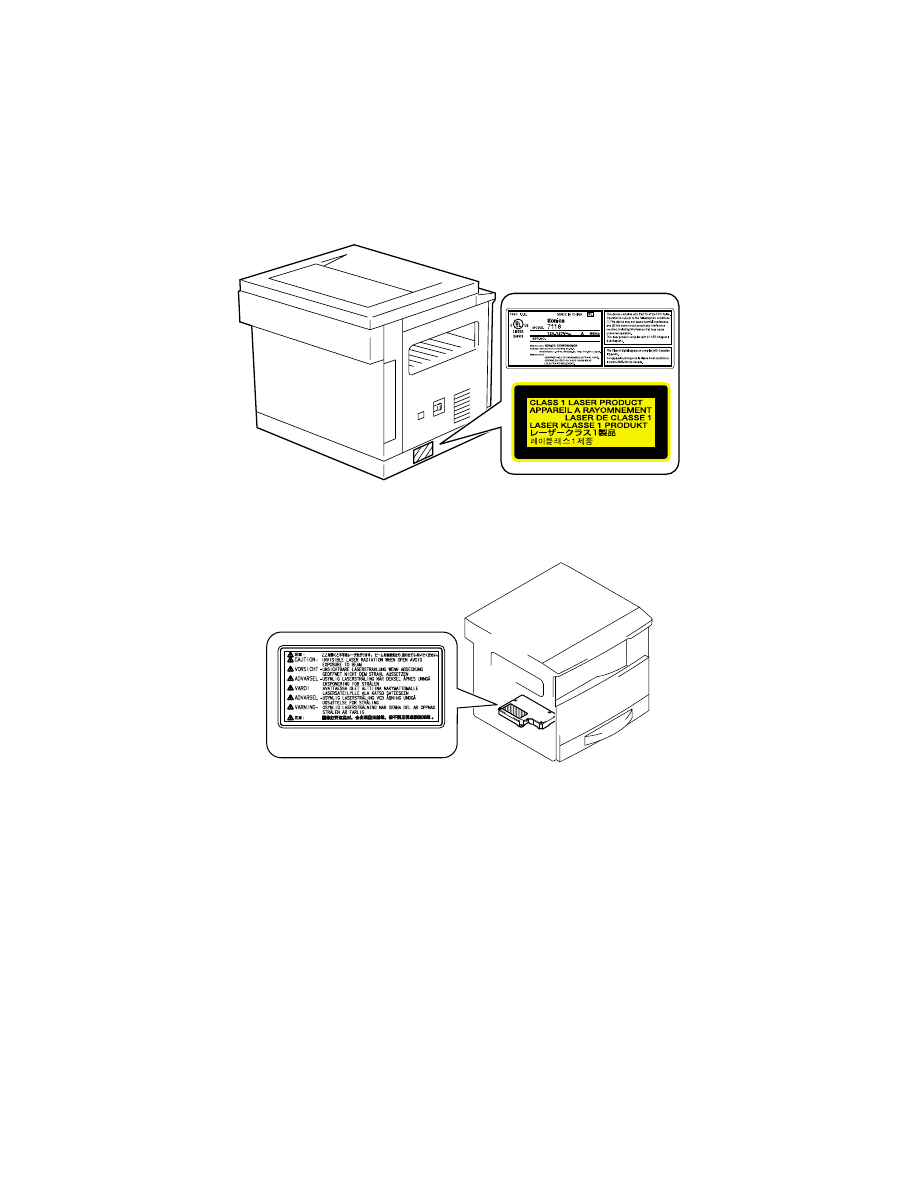
1-3.
LASER SAFETY LABEL
• A laser safety labels is attached to the outside of the machine as shown below.
1-4.
LASER CAUTION LABEL
• A laser caution label is attached to the inside of the machine as shown below.
1-5.
PRECAUTIONS FOR HANDLING THE LASER EQUIPMENT
• When laser protective goggles are to be used, select ones with a lens conforming to the
above specifications.
• When a disassembly job needs to be performed in the laser beam path, such as when
working around the printerhead and PC Drum, be sure first to turn the copier OFF.
• If the job requires that the copier be left ON, take off your watch and ring and wear laser
protective goggles.
• A highly reflective tool can be dangerous if it is brought into the laser beam path. Use
utmost care when handling tools on the user’s premises.
Laser safety label
4022D501AA
D-5
2.
SERVICE INSTRUCTIONS
2-1.
IDENTIFICATION OF FUSES AND CIRCUIT BREAKERS
Control Board (PWB-C)
125 V 3 A
DC Power Supply (PU1)
100 V system 125 V 15 A (F2)
200 V system 250 V 6.3 A (F2)
4021D006AA
Thermoswitch 1 (TS1)
250 V 7.5 A/125 V 15 A
D-6
2-2.
PARTS WHICH MUST NOT BE TOUCHED
(1)
Red Painted Screws
Purpose of Application of Red Paint
Red painted screws show that the assembly or unit secured can only be adjusted or set at
the factory and shall not be readjusted, set, or removed in the field.
If it becomes unavoidably necessary to disassemble any of these assemblies and units,
disassembly may be done provided that the conditions permitting reassembly are met.
Note also that when two or more screws are used on the part in question, only one repre-
sentative screw may be marked with red paint.
(2)
Variable Resistors on Board
Do not turn the variable resistors on boards for which no adjusting instructions are given in
“ADJUSTMENT.”
Other Screws not Marked with Red Paint
<PH Unit>
<IR Unit>
PH Unit
PH Unit base plate
Left side face
Right side face
D-7
3.
DISASSEMBLY/REASSEMBLY
3-1.
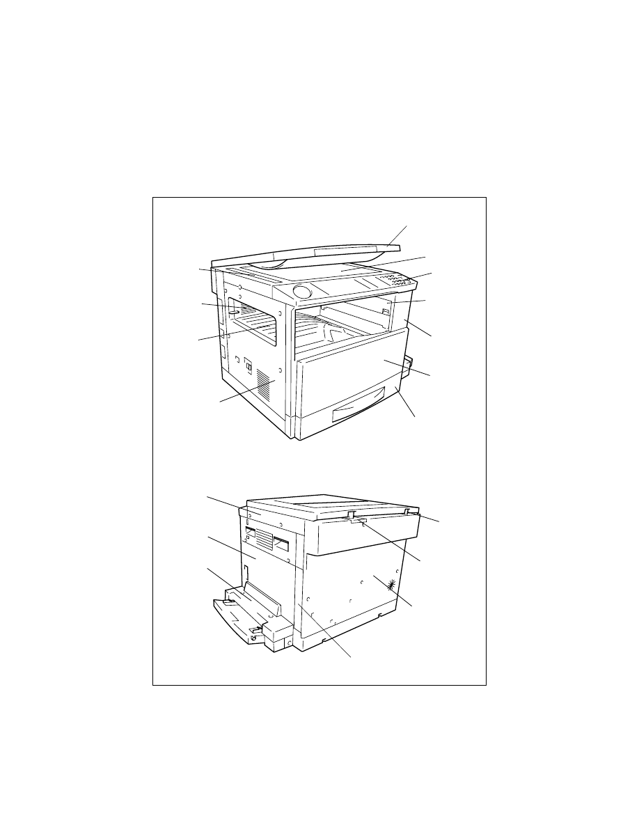
DOORS, COVERS, AND EXTERIOR PARTS: IDENTIFICATION
AND REMOVAL PROCEDURES
1
2
3
4
5
6
7
9
10
11
12
13
14
16
17
18
15
8

D-8
No.
Part Name
Removal Procedure
1
Original Cover
Pull the Original Cover straight up.
2
Original Glass
Remove no. 18.
→
Remove two holding brackets or no. 11 and
the Original Glass.
3
Control Panel
Remove two control panel mounting screws.
→
Remove two
ground wire mounting screws.
→
Remove one flat cable and
unplug one connector.
4
Right Inside Cover
Remove no. 5.
→
Remove one Right Inside Cover mounting
screw.
5
Front Cover
Remove no. 3.
→
Open the Front Door and remove six Front
Cover mounting screws.
6
Front Door
Open the Front Door and remove one band mounting screw.
→
Snap off one C-clip.
7
1st Tray
Slide out the 1st Tray.
→
Remove the fixing brackets on the right
and left.
8
Left Cover
Remove no. 3.
→
Remove no. 5.
→
Remove no. 14.
→
Remove
five Left Cover mounting screws.
9
Upper Cover
Remove no. 3.
→
Remove no. 5.
→
Remove no. 14.
→
Remove
no. 8.
→
Remove two screws and two Upper Cover mounting
screws.
10 Rear Inside Cover
Remove no. 3.
→
Remove no. 5.
→
Remove no. 14.
→
Remove
no. 8.
→
Remove no. 9.
→
Remove no. 4.
→
Remove two Rear
Inside Cover mounting screws.
11 ADF Glass
Remove two ADF Glass mounting screws.
12 Left Hinge
Remove no. 14.
→
Remove three Left Hinge mounting screws.
13 Right Hinge
Remove no. 14.
→
Remove three Right Hinge mounting screws.
14 Rear Cover
Remove six Rear Cover mounting screws.
15 Rear Right Cover
Remove no. 14.
→
Remove one Rear Right Cover mounting
screw.
16
Multiple Bypass
Cover (when the
option is mounted)
Remove two Multiple Bypass Cover mounting screws.
17 Right Door
Remove no. 14.
→
Remove no. 15.
→
Remove three Right Door
mounting screws.
18 Right Cover
Remove no. 3.
→
Remove no. 5.
→
Remove no. 14.
→
Remove
four Right Cover mounting screws.
D-9
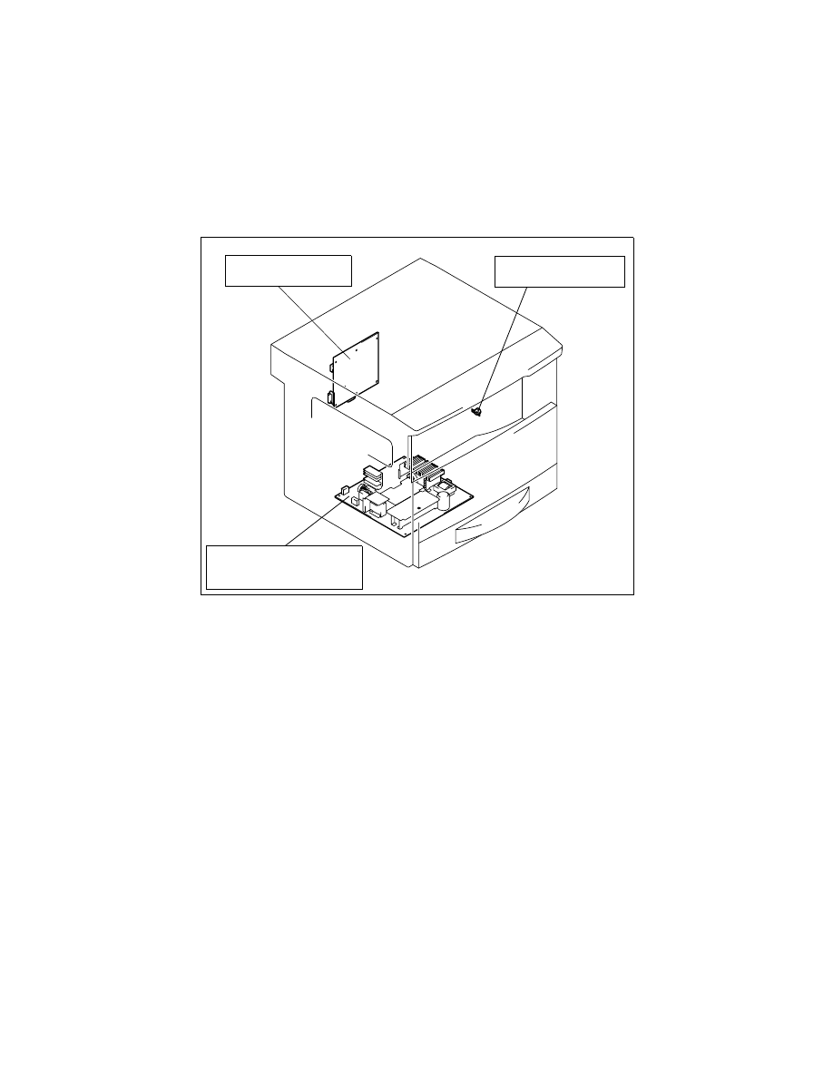
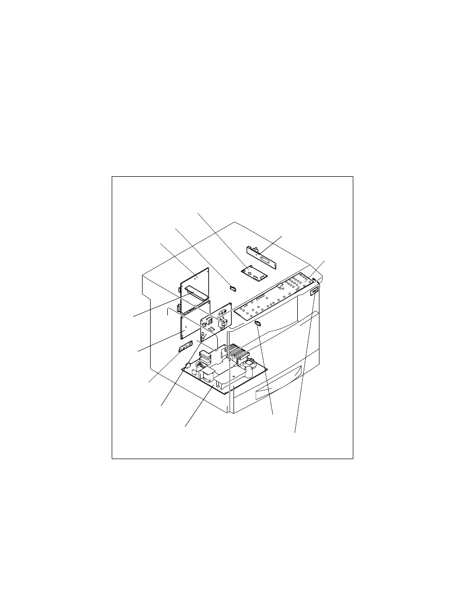
3-2.
REMOVAL OF CIRCUIT BOARDS AND OTHER ELECTRICAL
COMPONENTS
• When removing a circuit board or other electrical component, refer to “PRECAUTIONS
FOR HANDLING THE PWBs” and follow the corresponding removal procedures.
• The removal procedures given in the following omit the removal of connectors and
screws securing the circuit board support or circuit board.
• Where it is absolutely necessary to touch the ICs and other electrical components on the
board, be sure to ground your body.
PWB-J
PU3
PWB-R2
PU1
HV1
PWB-I
PWB-A
PU2
PWB-C
PWB-R1
PWB-A
Job Tray (IT-102): Option
Shifting Unit (IS-101): Option
PWB-B
Job Tray (IT-102): Option
4021D009AA
D-10
Job Tray (IT-102): Option
Shifting Unit (IS-101): Option
(1)
Removal of the Master Board
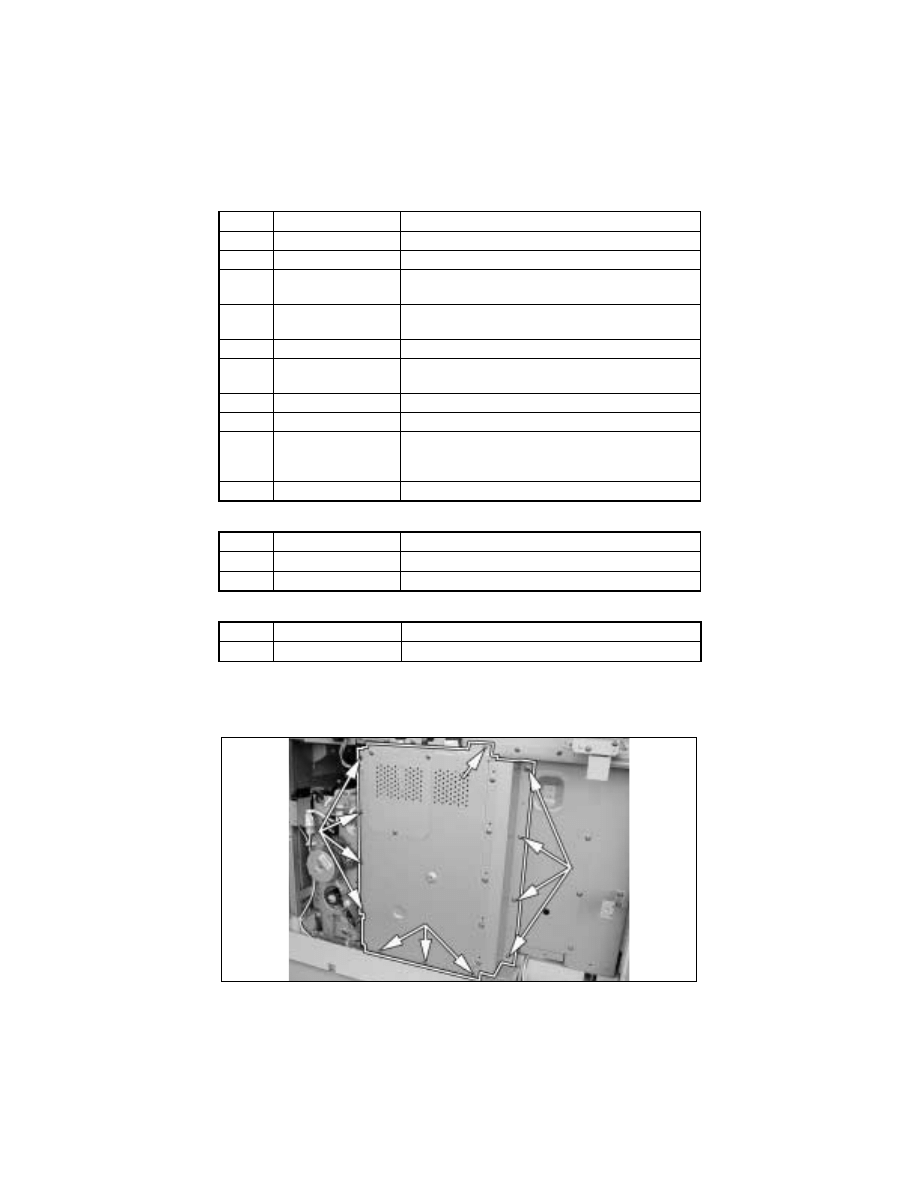
1. Remove the Rear Cover.
2. Remove 12 screws and the PWB Cover Assy.
Symbol
Part Name
Removal Procedure
PWB-A
Master Board
☞
D-10
PWB-C
Control Board
☞
D-11
PWB-I
Paper Size Detecting
Board
Remove the Rear Cover.
→
Remove the PWB Assy.
→
Remove two screws and the PWB-I Assy.
→
PWB-I
PWB-J
CCD Board
☞
D-23
✽
Remove the CCD Unit as a unit.
PWB-R1 Fusing Board
Remove the Fusing Unit.
→
PWB-R1
PWB-R2
Pre-Image Transfer
Board
Open the Right Door.
→
PWB-R2
PU1
DC Power Supply
☞
D-13
PU2
Inverter Board
☞
D-23
PU3
Control Panel
Remove two control panel mounting screws.
→
Remove two ground wire mounting screws.
→
Remove
one flat cable and unplug one connector.
→
PU3
HV1
High Voltage Unit
☞
D-11
Symbol
Part Name
Removal Procedure
PWB-A
Main Board
☞
D-46
PWB-B
Paper Detecting Board
☞
D-48
Symbol
Part Name
Removal Procedure
PWB-A
Main Board
☞
D-49
D-11
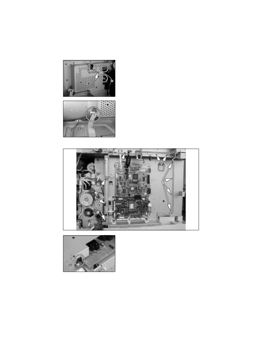
(2)
Removal of the Control Board
1. Remove the Rear Cover.
2. Remove the PWB Cover Assy.
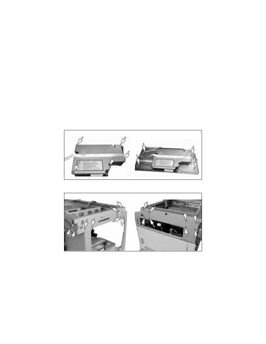
(3)
Removal of the High Voltage Unit
1. Remove the control panel, Front Cover, Rear Cover, Left Cover, Upper Cover, Right
Inside Cover, and Rear Inside Cover.
2. Remove the PWB Cover Assy.
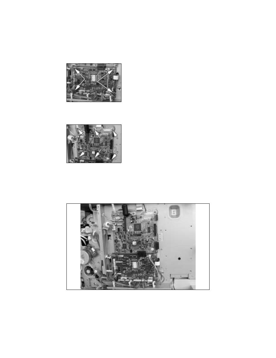
3. Unplug all connectors from the Master Board (except for PJ20) and from the Control
Board.
4. Remove the harness from seven wiring saddles and two edge covers.
3. Unplug all connectors (but PJ20) from the Master
Board.
4. Remove four screws and the Master Board.
3. Unplug all connectors from the Control Board.
4. Remove six screws and the Control Board.
D-12
7. Remove ten screws and the PWB Assy.
5. Unplug three connectors from the High Voltage
Unit and remove the harness from one wiring
saddle.
6. Remove the harness from one wiring saddle.
8. Remove the harness from one wiring saddle of
the High Voltage Unit cover.
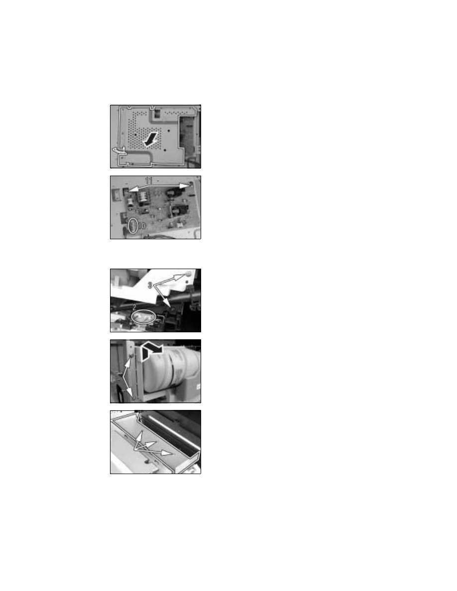
D-13
(4)
Removal of the DC Power Supply
1. Remove the control panel, Front Cover, Rear Cover, Left Cover, and Upper Cover.
9. Remove nine screws and the High Voltage Unit
cover.
10. Unplug two connectors from the High Voltage
Unit.
11. Remove two screws and the High Voltage Unit.
2. Unplug two connectors of the Hopper Assy.
3. Remove two Hopper mounting screws on the
right.
4. Remove two Hopper mounting screws on the left
and the Hopper Assy.
5. Remove three screws and the Power Supply
Right Cover.

D-14
6. Remove four screws and the Power Supply Left
Cover.
7. Unplug one connector and remove the harness
from one edge cover.
8. Unplug one connector and remove the harness
from one wiring saddle.
9. Unplug one connector and remove the harness
from one wiring saddle.
10. Unplug three connectors and remove the har-
ness from two wiring saddles.
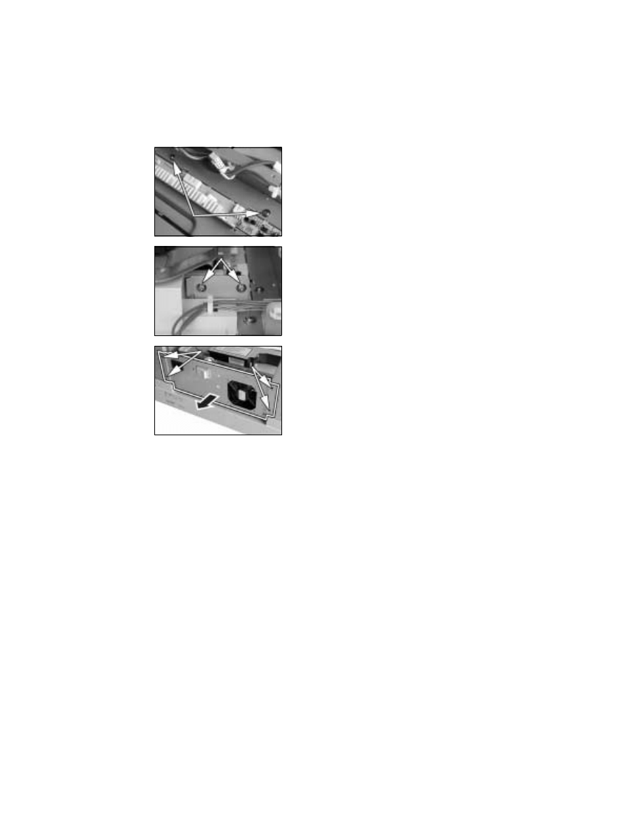
D-15
11. Remove two screws.
12. Remove two screws.
13. Remove four screws and the DC Power Supply.
D-16
3-3.
MAINTENANCE SCHEDULE
PM
P
a
rt
s
Mai
n
tena
nc
e
C
y
c
le
(K
)
P
a
rt
No
.
Q
ty
Ref.
Pa
g
e
C
o
unter
(
*3)
A
s
s
o
c
iat
ed P
robl
e
m
s
C
lean
R
epl
a
c
e
Pa
p
e
r T
a
k
e
-U
p
/
T
rans
por
t S
e
c
ti
o
n
P
aper
T
a
k
e
-U
p R
o
ll (
1
s
t T
ray
)
W
hen a
ma
lf
un
c
ti
o
n
oc
c
u
rs
150
27A
E
430
1
✱
1
☞
D-1
8
1s
t T
ra
y
P
ape
r t
a
k
e
-up f
a
ilu
re, do
u-
b
le f
e
ed
P
aper
S
epar
ator
R
o
ll A
s
s
y
150
111T
-501
✱
1
☞
D-1
8
D
oubl
e f
eed
Mul
ti
B
y
pas
s
P
ape
r T
a
k
e
-U
p R
o
ll
(M
ul
ti
pl
e
B
y
pas
s
)
150
14A
H
4001
✱
1
☞
D-4
2
B
y
pas
s
T
ray
P
ape
r t
a
k
e
-up f
a
ilu
re, do
u-
b
le f
e
ed
M
u
lt
i B
y
p
a
s
s
Se
p
a
ra
to
r R
o
ll As
sy
(M
ul
ti
pl
e
B
y
pas
s
)
150
111T
-501
✱
1
☞
D-4
2
D
oubl
e f
eed
C
lean
ing P
a
d
4
0
27A
E
270
2
✱
1
☞
D-1
9
IU Li
fe
F
a
ilur
e t
o
r
e
mov
e
tone
r o
ff
co
m
p
le
te
ly
, f
ilm
in
g
R
ight
S
y
nc
h
ron
iz
ing
R
o
ller
—
—
—
☞
D-1
9
—
D
ir
ty
i
m
age
Left S
y
nc
hr
oni
z
ing R
o
lle
r
—
—
—
☞
D-1
9
D
ir
ty
i
m
age
B
y
pas
s
T
rans
por
t R
o
lle
r
—
—
—
☞
D-2
0
P
ape
r m
is
feed
O
p
ti
ca
l S
e
ct
io
n
Mi
rr
o
rs
an
d l
e
ns
80
—
—
—
☞
D-2
1
IR
S
c
anner
r
a
ils
/bus
hi
ng
s
8
0
—
—
—
☞
D-2
2
O
ri
g
in
al
G
las
s
8
0
—
—
—
☞
D-2
1
P
H
S
e
c
ti
o
n
P
H
w
indow
W
hen a
ma
lf
un
c
ti
o
n
oc
c
u
rs
——
—
☞
D-2
9
—
Imag
e
noi
s
e
(
w
hi
te l
ine
s
)
Im
agi
n
g
U
n
it
(
*2)
PC
D
ru
m
W
hen a
ma
lf
un
c
ti
o
n
oc
c
u
rs
40
—
1
☞
D-3
0
IU Li
fe
Imag
e noi
s
e
(
w
hi
te l
ine
s
)
C
lean
ing B
la
d
e
—
40
27A
E
270
1
✱
1
☞
D-3
2
P
C
D
rum
P
ape
r S
epar
ator
F
in
ger
40
—
—
—
☞
D-3
2
P
C
D
rum
C
har
ge C
o
ro
n
a
A
s
s
y
—
4
0
27A
E
-250
✱
1
☞
D-3
2
D
e
v
e
lo
per
(
s
tar
ter
)
—
40
—
1
☞
D-3
3
D
s
c
o
llar
40
—
—
—
☞
D-3
3
D-17
PM
P
a
rt
s
Mai
n
tenanc
e C
y
c
le
(K
)
P
a
rt
No
.
Q
ty
Re
f.
P
age
C
oun
ter
(
*3)
A
s
s
o
c
iated
P
robl
em
s
C
lea
n
R
ep
la
c
e
Im
agi
ng U
n
it
(
*2)
D
e
v
e
loper
S
c
atte
ri
ng
P
re
v
enti
on P
late
4
0
—
—
—
☞
D-3
3
IU Li
fe
C
har
ge N
e
utr
a
liz
in
g
S
h
eet
—
4
0
27A
E
1066
✱
1
☞
D-3
2
P
re-
Imag
e T
rans
fer
U
pper
G
u
id
e P
late
4
0
—
—
—
☞
D-3
4
O
z
one F
ilt
er
(E
ur
ope
)
—
15
0
27A
E
1062
✱
1
☞
D-3
1
(A
reas
othe
r th
an E
u
ro
pe)
3
0
0
☞
D-3
1
O
z
o
ne F
ilt
er
Im
age T
rans
fe
r
Se
c
tio
n
Imag
e T
rans
fer
R
o
ller
A
s
s
y
—
1
50
27A
E
-451
✱
1
☞
D-3
6
Image
T
ra
n
s
-
fe
r R
o
lle
r/
F
u
s
ing U
n
it
P
re-
Imag
e T
rans
fer
Low
e
r G
u
ide P
late
W
h
en a
mal
func
ti
o
n
oc
c
u
rs
——
—
☞
D-3
6
—
D
ir
ty
im
a
g
e
C
har
ge N
e
utr
a
liz
in
g
P
late
—
—
—
☞
D-3
6
—
M
is
feed
due to
paper
no
t
p
ro
per
ly
s
epar
ated
fr
om
PC
D
ru
m
F
u
si
n
g
S
e
ct
io
n
F
u
s
ing U
n
it
(1
0
0
-V
s
y
s
tem)
—
1
5
0
27A
E
-530
✱
1
☞
D-3
7
Image
T
ra
n
s
-
fe
r R
o
lle
r/
F
u
s
ing U
n
it
(2
0
0
-V
s
y
s
tem)
—
1
5
0
27A
F
-530
✱
1
☞
D-3
7
*1
:
R
e
pl
ac
e at
40
K
f
o
r r
e
com
m
en
de
d pl
a
in
p
a
p
e
r.
C
lea
n w
h
e
n
t
h
e
C
lea
ni
ng
P
a
d
i
s
f
u
ll
o
f p
a
p
e
r du
st
f
o
r
p
a
p
e
r of
ot
h
e
r t
y
pe
s
.
*2
: Th
e
li
fe
o
f
th
e
Im
a
g
in
g
U
n
it (
e
x
c
e
p
t
fo
r th
e
O
z
o
n
e
Fi
lte
r)
i
s
d
e
te
rm
in
e
d
b
y
th
e
p
e
ri
o
d
o
f tim
e
th
ro
u
g
h
w
h
ic
h
th
e
PC
D
ru
m
h
a
s t
u
rn
e
d
(
a
s
tr
a
n
s
la
te
d
t
o
a
n
eq
ui
v
a
le
nt
di
st
an
ce t
ra
vel
ed
).
T
h
e ma
in
tena
nc
e cy
cl
e in
t
h
e t
a
b
le
r
e
pr
es
en
ts
t
h
e n
u
m
b
e
r o
f co
pi
es
mad
e
i
n
t
h
e
st
an
da
rd
c
o
p
y
mo
de (
A
4C
, 2P
J)
w
h
ic
h
ma
y
d
if
fer
d
e
p
end
ing o
n
co
nd
it
io
n
s
in
w
h
ic
h t
h
e
c
o
p
ie
rs ar
e
u
s
e
d
am
on
g di
ff
e
re
n
t u
s
e
rs
.
*3
:
F
o
r d
e
ta
ils
, s
e
e
SW
ITC
H
ES O
N
P
W
Bs
, TE
C
H
. R
E
P
. SE
TTI
N
G
S
.
NO
T
E
•
k =
1
,00
0 co
pi
es
•
Th
e
c
o
n
te
n
ts
o
f th
is
m
a
in
te
n
a
n
c
e
s
c
h
e
d
u
le
a
re
s
u
b
je
c
t
to
c
h
a
n
g
e
w
ith
o
u
t n
o
ti
c
e
.
•
F
o
r p
a
rt
nu
m
b
e
rs,
s
e
e P
a
rt
s M
a
nua
l
an
d P
a
rt
s M
o
di
fi
c
a
ti
o
n
N
o
ti
ce.
D-18
3-4.
PAPER TAKE-UP/TRANSPORT SECTION
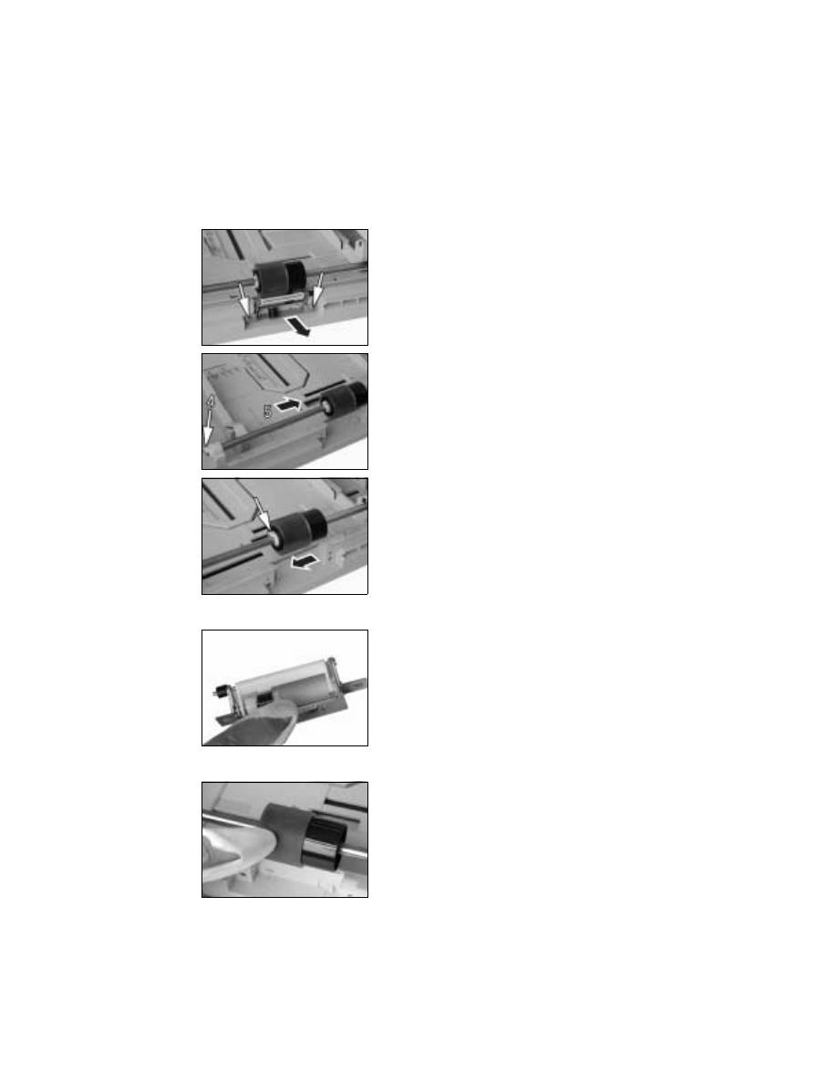
(1)
Removal of the Paper Separator Roll Assy and Paper Take-Up Roll
(2)
Cleaning of the Paper Separator Roll
(3)
Cleaning of the Paper Take-Up Roll
1. Slide out the 1st Tray.
2. Remove two screws and the Paper Separator
Roll Assy.
3. Press down the Paper Lifting Plate.
4. Snap off one C-clip from the Paper Take-Up Roll
Assy.
5. Slide the Paper Take-Up Roll Assy to the rear so
that it can be pulled off the bushing at the front.
6. Snap off one C-clip and remove the Paper Take-
Up Roll.
1. Remove the Paper Separator Roll Assy.
2. Using a soft cloth dampened with alcohol, wipe
the Paper Separator Roll clean of dirt.
1. Slide out the 1st Tray.
2. Remove the Paper Separator Roll Assy.
3. Using a soft cloth dampened with alcohol, wipe
the Paper Take-Up Roll clean of dirt.
D-19
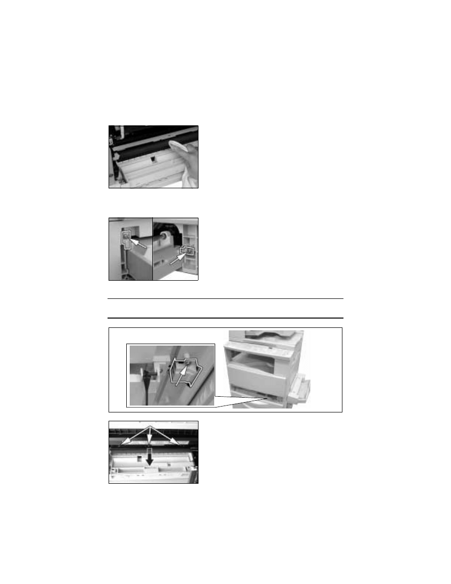
(4)
Cleaning of the Right and Left Synchronizing Rollers
1. Remove the Imaging Unit.
(5)
Removal of the Cleaning Pad
1. Remove the Imaging Unit.
4. Remove one screw and the Synchronizing Roller Sensor Assy.
NOTE
• Do not unplug the sensor harness connector.
2. Using a soft cloth dampened with alcohol, wipe
the Right and Left Synchronizing Rollers clean of
dirt.
2. Remove two screws and the stopper.
3. Remove the 1st Tray.
5. Remove three screws and the Cleaning Pad.
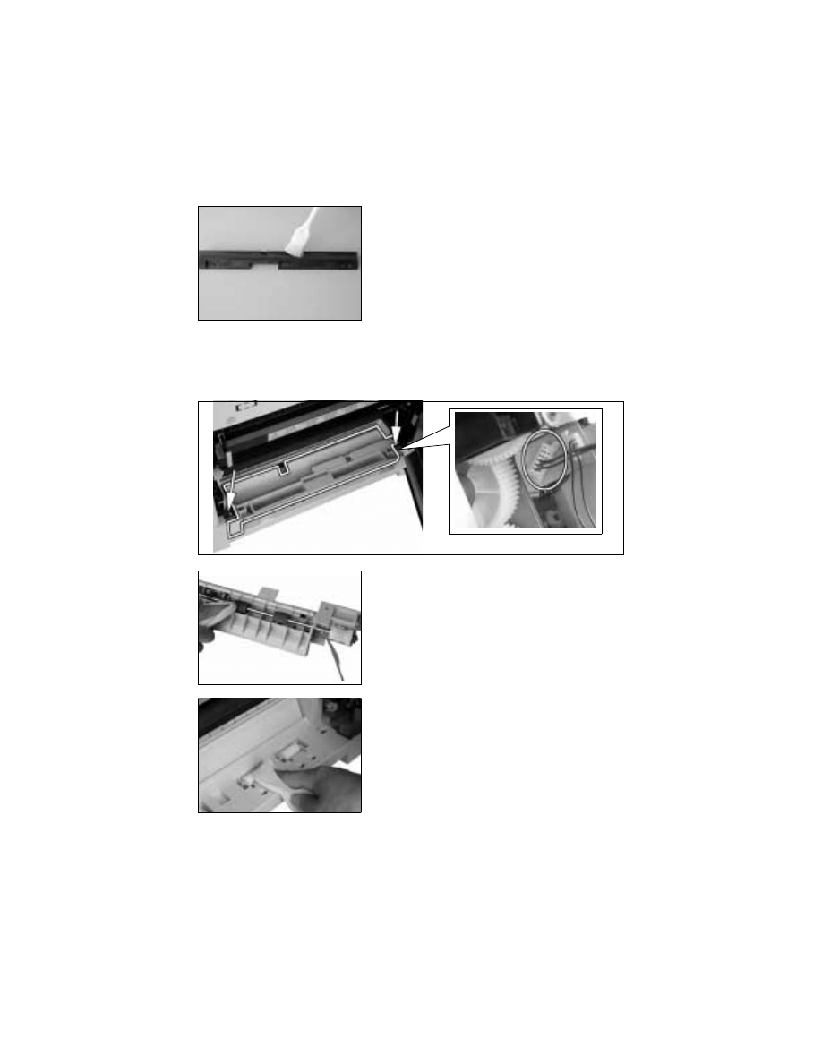
D-20
(6)
Cleaning of the Cleaning Pad
(7)
Cleaning of the Bypass Transport Roller
1. Remove the Imaging Unit.
2. Remove two screws, unplug one connector, and remove the Bypass Transport Roller
Assy.
1. Remove the Cleaning Pad.
2. Using a brush, whisk dust and dirt off the Clean-
ing Pad.
3. Using a soft cloth dampened with alcohol, wipe
the Bypass Transport Roller clean of dirt.
4. Using a soft cloth dampened with alcohol, wipe
the rolls clean of dirt.
D-21
3-5.
OPTICAL SECTION
(1)
Cleaning of the Original Glass and ADF Glass
(2)
Cleaning of Mirrors
(3)
Cleaning of the Lens
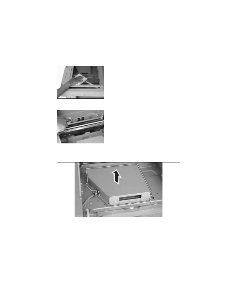
1. Remove the Original Glass.
2. Remove 15 screws and the CCD Unit cover.
1. Using a soft cloth dampened with alcohol, wipe
the Original Glass and ADF Glass clean of dirt.
1. Remove the Original Glass.
2. Using a soft cloth dampened with alcohol, wipe
the mirrors clean of dirt.
D-22
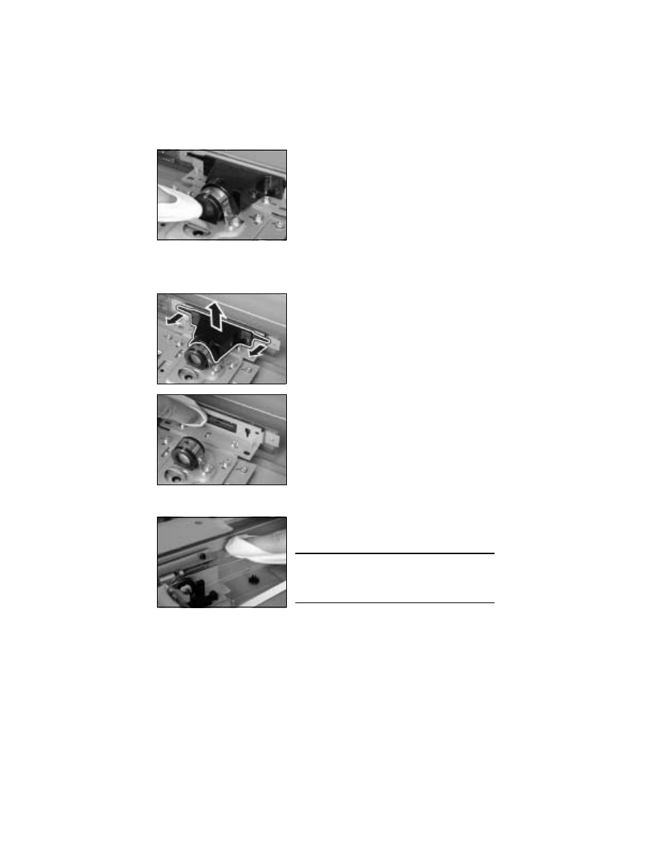
(4)
Cleaning of the CCD Sensor
1. Remove the Original Glass.
2. Remove 15 screws and the CCD Unit cover.
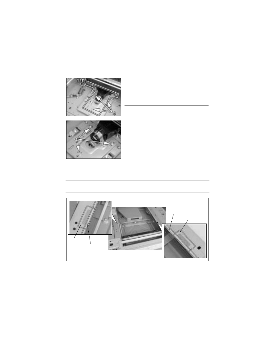
(5)
Cleaning of the Scanner Rails/Bushings
3. Using a soft cloth dampened with alcohol, wipe
the Lens clean of dirt.
3. Remove the Lens cover.
4. Using a soft cloth dampened with alcohol, wipe
the CCD Sensor clean of dirt.
1. Remove the Original Glass.
2. Using a soft cloth dampened with alcohol, wipe
the Scanner rails/bushings clean of dirt.
NOTE
• After the Scanner rails/bushings have been
cleaned, apply oil (copier lubricant A or FLOIL
947P).
D-23
(6)
Removal of the CCD Unit
1. Remove the Original Glass.
2. Remove 15 screws and the CCD Unit cover.
(7)
Removal of the Scanner, Exposure Lamp, and Inverter Board
1. Remove the control panel, Front Cover, Rear Cover, and Original Glass.
2. Remove the foam seal and mylar, one each at the front and rear.
NOTE
• Ready a new foam seal and mylar and affix them after the procedure.
3. Unplug one connector.
4. Remove three screws and the CCD Unit.
NOTE
• NEVER attempt to loosen or remove screws that
are not specified when removing the CCD Unit.
<<Reinstallation of the CCD Unit>>
• Temporarily secure the CCD Unit with each of the
screws at the center of each slot.
• After the CCD Unit has been installed, adjust the
position of the CCD Unit.
☞
D-65
Foam Seal
Mylar
Foam Seal
Mylar
Rear
Front
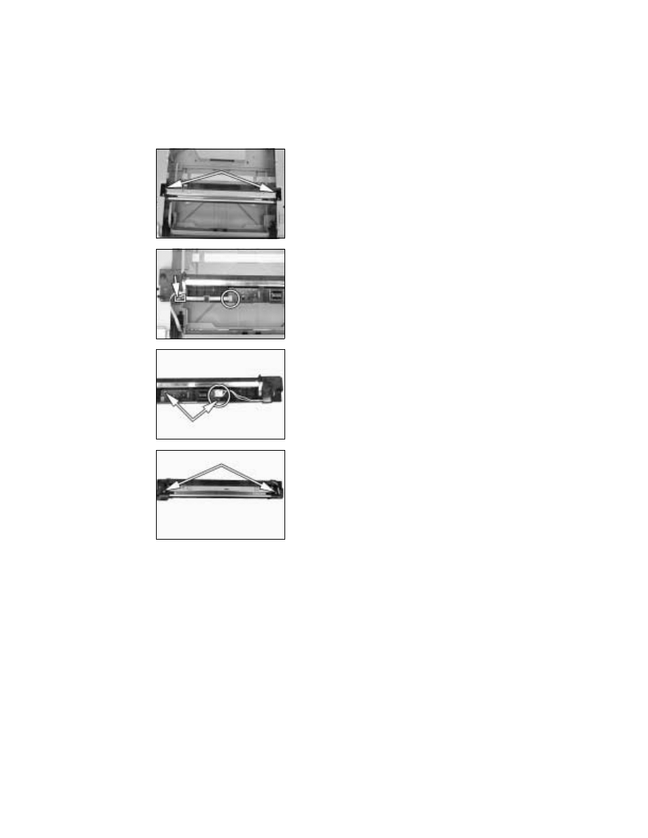
D-24
3. Remove two Scanner mounting screws (to which
no red paint has been applied).
4. Remove one screw and the cable holder.
5. Remove the flat cable from the Inverter Board
and then remove the Scanner.
6. Unplug one connector from the Inverter Board.
7. Remove two screws and the Inverter Board.
8. Remove two screws and the Exposure Lamp.
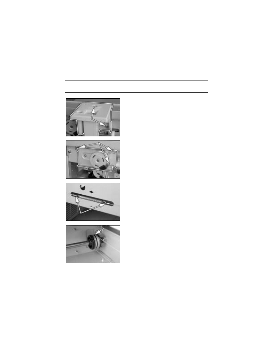
D-25
(8)
Removal of the Scanner Drive Cables
1. Remove the control panel, Front Cover, Rear Cover, Left Cover, Right Cover, Original
Glass, and ADF Glass.
2. Remove the Scanner.
NOTE
• Remove the two red painted screws to remove the Scanner in this step.
3. Remove two screws and the Exposure Lamp.
4. Loosen three screws to free the Scanner Motor
Assy.
5. Unhook the spring from the cable hooks at the
front and rear.
6. Remove the front cable from the cable pulley.
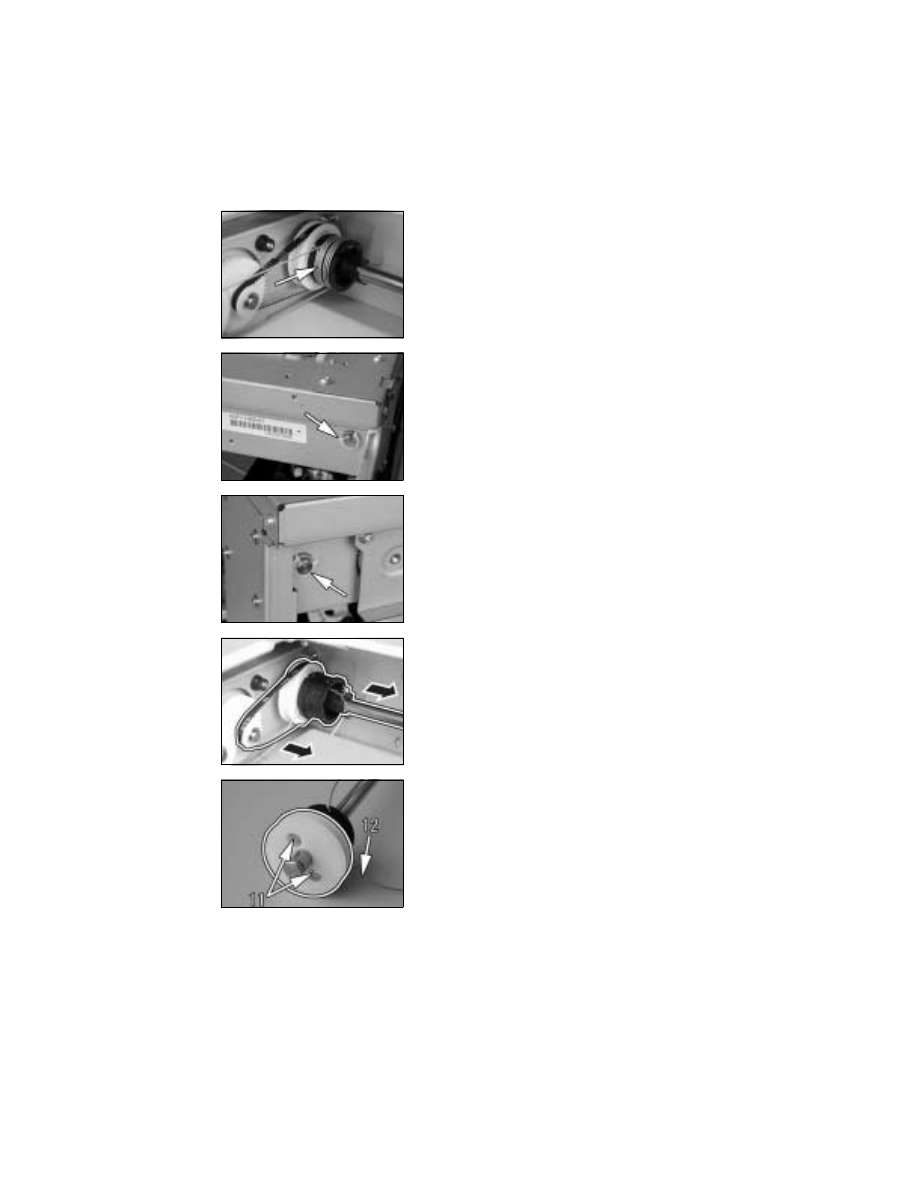
D-26
7. Remove the rear cable from the cable pulley.
8. Snap off one C-ring from the front side of the pul-
ley assy.
9. Snap off one C-ring from the rear side of the pul-
ley assy.
10. Remove the belt and the pulley assy.
11. Remove two screws and the pulley.
12. Remove the rear cable.
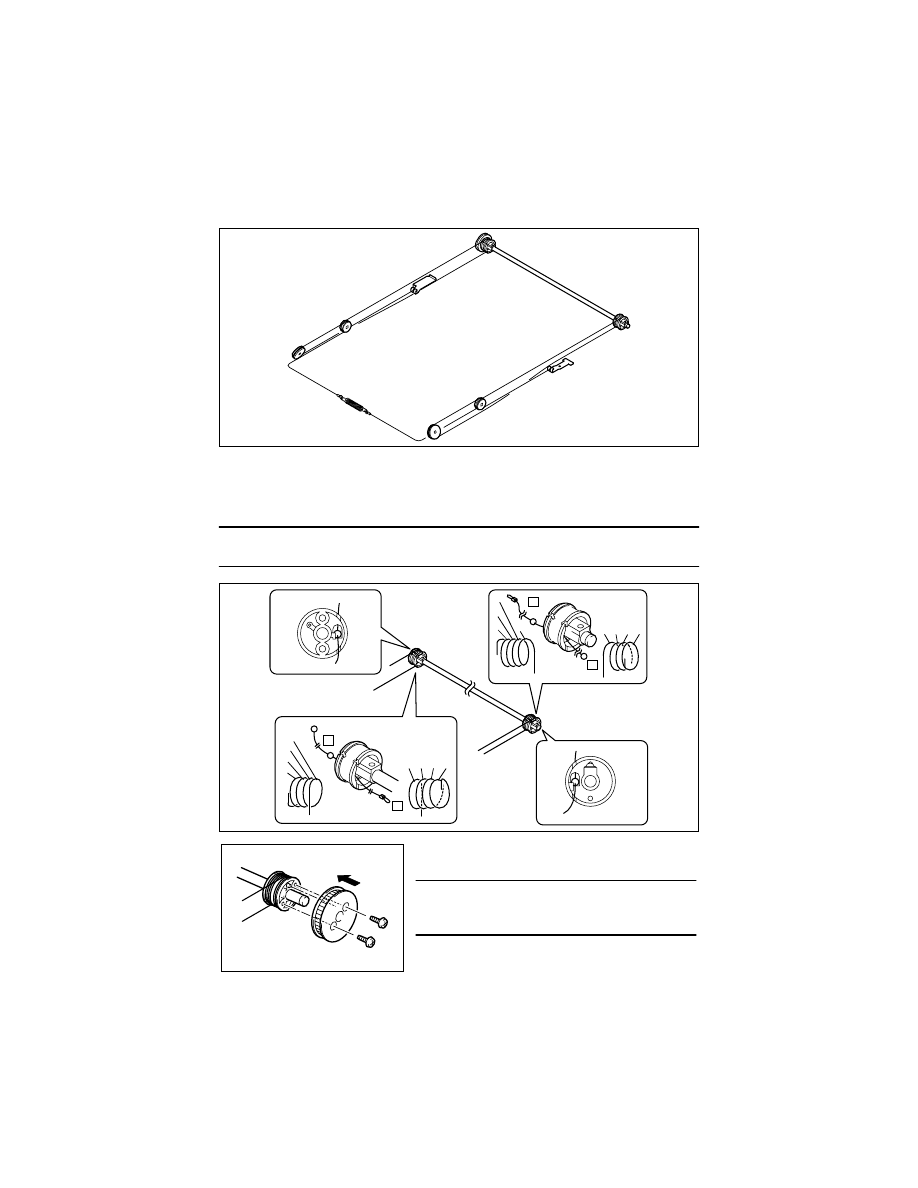
D-27
(9)
Winding of the Scanner Drive Cables
1. Wind the cable around the rear cable pulley of the pulley assy from side B toward side A
and then secure the cable with tape.
2. Wind the cable around the front cable pulley of the pulley assy from side A toward side
B and then secure the cable with tape.
NOTE
• Make sure that no part of the cable rides on the other.
Rear
Front
4022D003AA
Bead Position
Rear
Front
Bead Position
Winding
Direction on Side B
A
B
➀
➁
➂
➃
Winding Direction
on Side A
➀
➁
➂
➃
➀
➁
➂
➃
A
B
Winding Direction on Side B
Winding
Direction on
Side A
➃
➂
➁
➀
3. Secure the pulley to the rear cable pulley using
two screws.
NOTE
• Make sure that the pulley is doweled to the cable
pulley.
4022D005AA
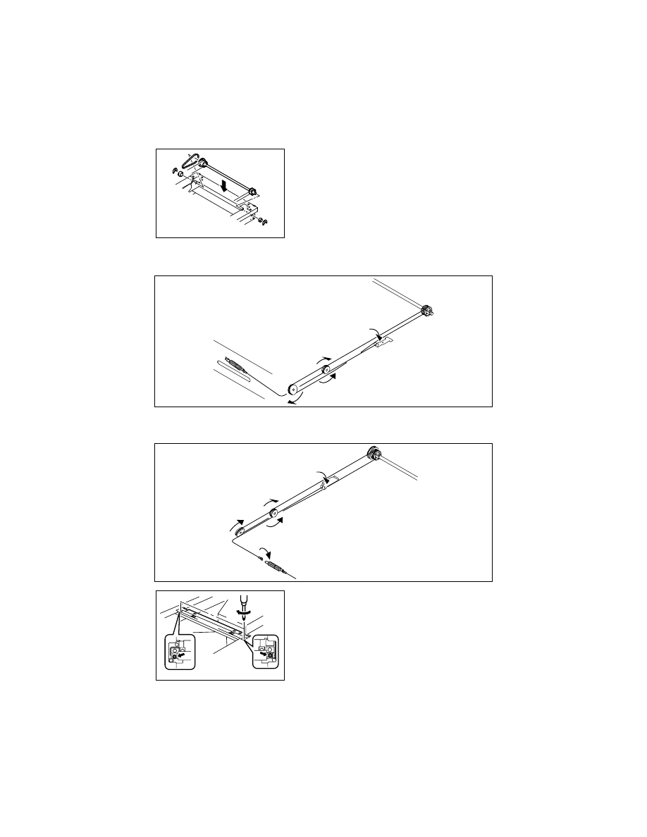
D-28
5. Wind the cable at the front.
6. Hook the spring onto the cable hook and hook the spring onto the frame.
7. Wind the cable in the rear.
8. Secure the cables at the front and rear with a spring.
4. Mount the pulley assy using two C-rings.
4022D006AB
4022D007AB
4022D008AB
9. Temporarily secure the Scanner to the front and
rear cables.
10. Perform the Focus-Positioning of the Scanner
and 2nd/3rd Mirrors Carriage.
☞
D-64
4022D009AA
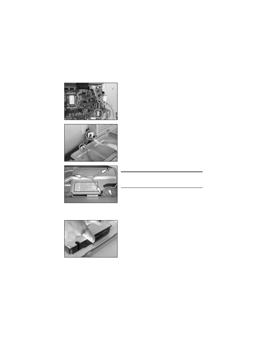
D-29
3-6.
PH
(1)
Removal of the PH Unit
1. Remove the control panel, Front Cover, Rear Cover, Left Cover, and Upper Cover.
2. Remove the PWB Cover Assy.
(2)
Cleaning of the PH Window
1. Remove the Front Cover, Rear Cover, Left Cover, and Upper Cover.
3. Remove one flexible harness and unplug one
connector from the Master Board.
4. Remove the harness from one edge cover and
one wiring saddle.
5. Remove one screw and the ground wire.
NOTE
• To remove the ground wire, remove the screw
installed on the copier side.
6. Remove three screws and the PH Unit.
2. Wipe the PH window clean of dirt using a soft
cloth.
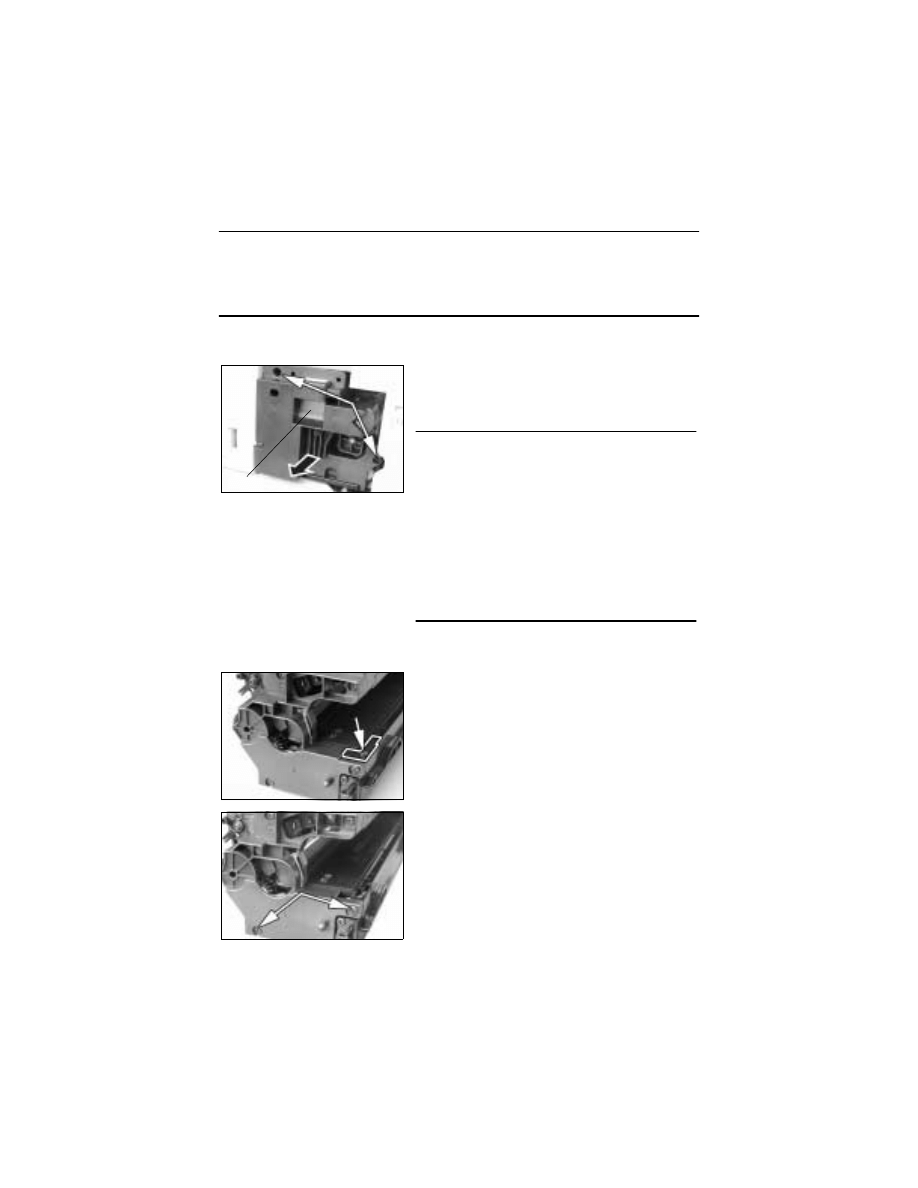
D-30
3-7.
Imaging Unit (IU)
NOTE
• When loading developer as part of the IU replacement procedure or when changing the
developer, remove the Toner Bottle and run “ATDC Sensor Automatic Adjustment” (F8)
twice to allow toner in the Spent Toner Recycling Duct and Toner Conveying Duct into the
Developer Mixing Chamber before removing the IU.
(1)
Removal of the IU
(2)
Disassembly of the IU
<Separating the Cleaning Assy from Developing Assy>
1. Open the Right Door.
2. Open the Front Door.
3. Remove two screws and, holding onto the handle
of the IU, take off the IU.
NOTE
• Before installing the IU, be sure to fully open the
Right Door.
If the IU is installed with the Right Door left ajar, the
PC Drum protective shutter will not open, interfer-
ing with the Image Transfer Roller gear, thus pro-
ducing noise.
• When inserting the IU, do that slowly and, when
you are sure that the drum gear contacts its mating
part, push the IU all the way into position. If this
step is done all at once, the drum gear could be
damaged.
Handle
1. Remove one screw in the rear of the IU and
remove the harness cover.
2. Remove two screws in the rear of the IU.
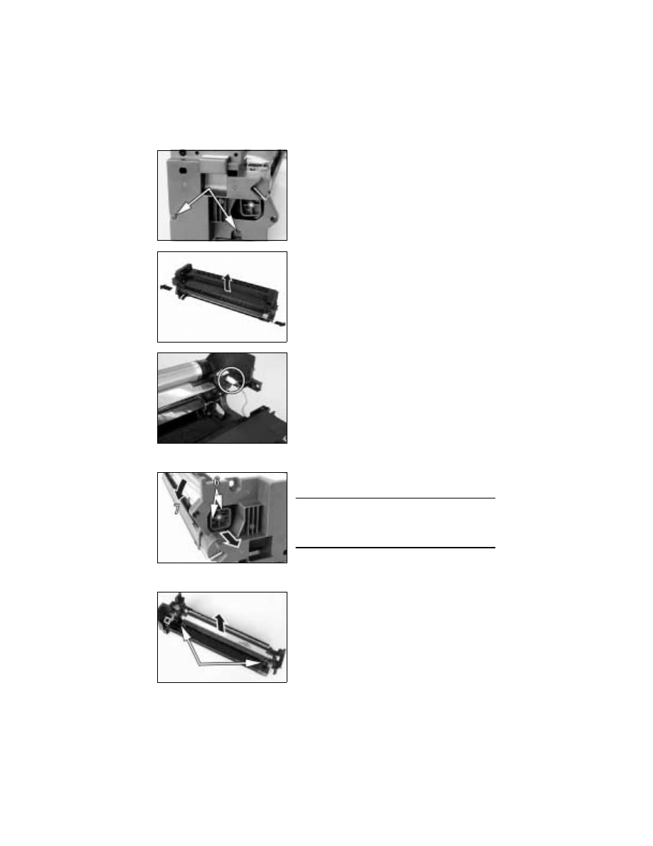
D-31
<Removal of the PC Drum>
<Removal of the Ozone Filter>
3. Remove two screws at the front of the IU.
4. Widen flaps on both ends (marked with A in the
illustration on the left) of the Cleaning Assy in the
direction of arrow and turn to take off the Clean-
ing Assy.
A
A
5. Unplug one connector of the Main Erase.
6. Remove two screws and the pivot shaft.
7. Remove the PC Drum.
NOTE
• When the PC Drum has been replaced, apply a
coat of toner to the surface of the PC Drum.
☞
D-34
8. Remove two screws and the Main Erase.
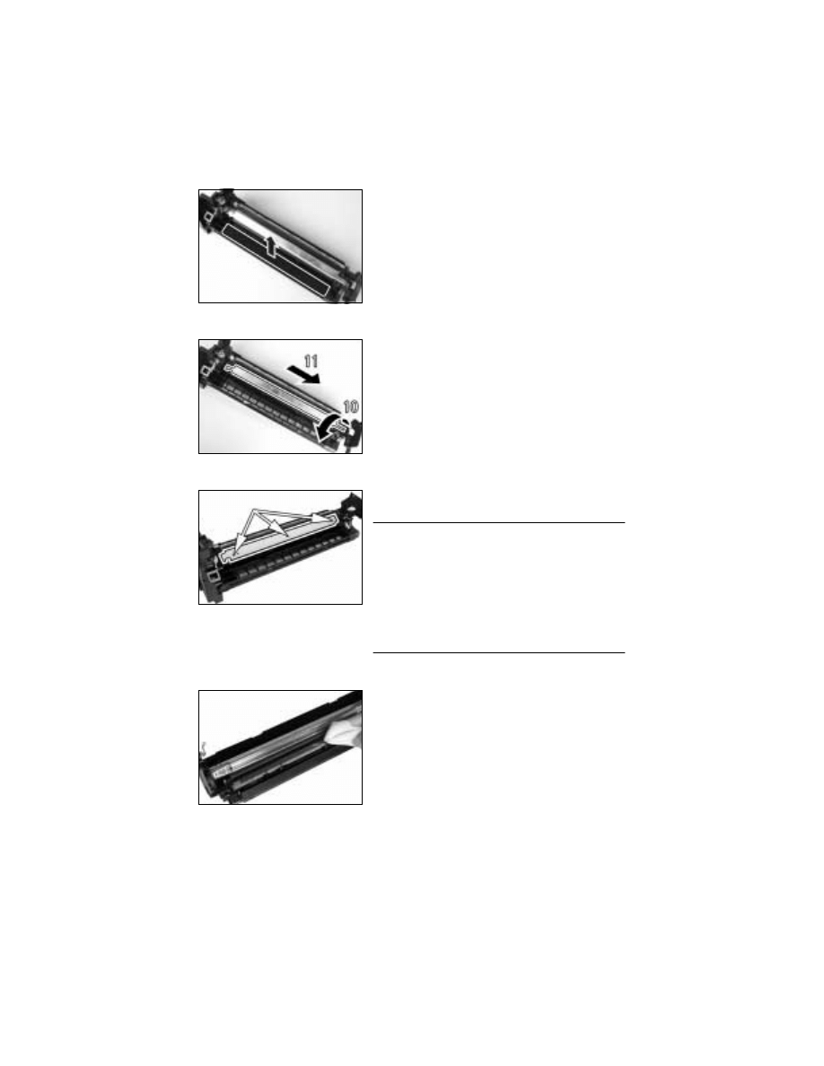
D-32
<Removal of the PC Drum Charge Corona Assy>
<Removal of the Charge Neutralizing Sheet and Cleaning Blade>
<Cleaning of the PC Drum Paper Separator Fingers>
9. Remove the Ozone Filter.
10. Turn the holder in the rear in the direction of the
arrow to remove it from the side bracket.
11. Slide out the PC Drum Charge Corona in the
direction of the arrow.
12. Remove three screws, the Charge Neutralizing
Sheet, and Cleaning Blade.
NOTE
• When securing the Cleaning Blade and Charge
Neutralizing Sheet, tighten screws in the order of
one on one edge, one at the center, and one on
the other edge.
• When the Cleaning Blade has been replaced,
apply a coat of toner to the surface of the PC
Drum.
☞
D-34
13. Using a soft cloth dampened with alcohol, wipe
the Paper Separator Fingers clean of dirt.
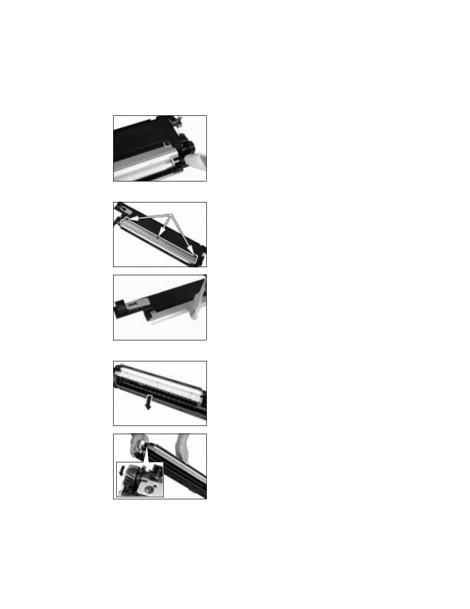
D-33
<Cleaning of the Ds Collars>
<Cleaning of the Developer Scattering Prevention Plate>
<Replacement of the Developer>
14. Using a soft cloth dampened with alcohol, wipe
the Ds Collars clean of dirt.
15. Remove three screws and the Developer Scatter-
ing Prevention Plate.
16. Using a brush, whisk dust and dirt off the surface
of the Developer Scattering Prevention Plate.
17. Dump the developer.
<<How to Dump Developer>>
• Dump developer on the Sleeve Roller by turning
the gear in the direction of the arrow with the
Developing Unit tilted as shown.
• Note at this time that turning the gear backward
could damage the mylar for cleaning the ATDC
Sensor.
• Dump developer until almost no developer sticks to
the Sleeve Roller.
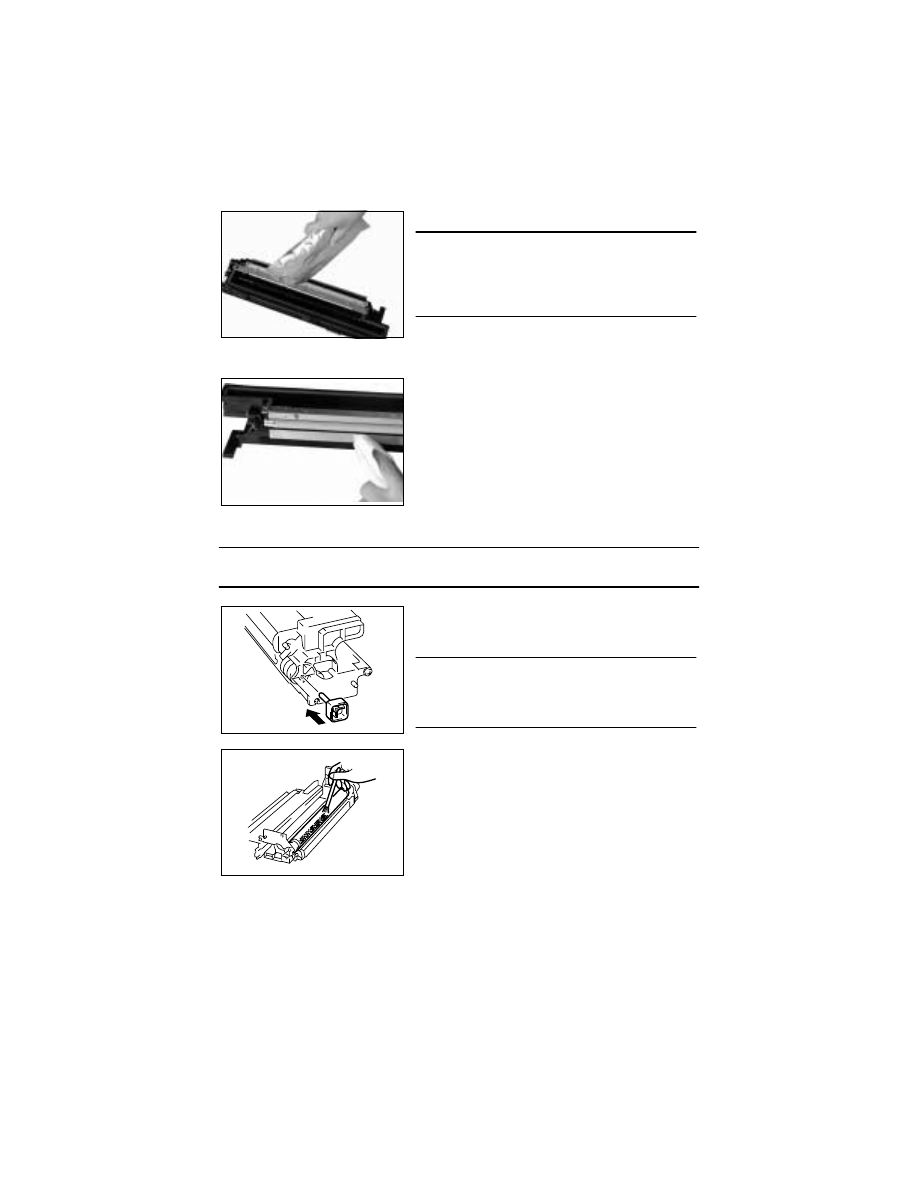
D-34
<Cleaning of the Pre-Image Transfer Guide Plate>
(3)
Application of Toner
NOTE
• Perform these steps when the PC Drum and/or Cleaning Blade have been replaced.
18. Pour one packet of developer.
NOTE
• Shake the packet of developer well before pouring.
• When the developer has been replaced, run
“ATDC Sensor Automatic Adjustment.”
☞
D-61
19. Using a soft cloth dampened with alcohol, wipe
the Pre-Image Transfer Guide Plate clean of dirt.
1. With the Cleaning Assy separated from the
Developing Assy, install the PC Positioning Jig in
the rear of the Developing Assy.
NOTE
• Ready the PC Positioning Jig (Pivot Shaft) sepa-
rately. (It can be ordered. For details, see the
Parts Manual.)
4022D034AA
2. Using a brush, apply a light coat of toner to the
surface of the PC Drum.
4021U008AB
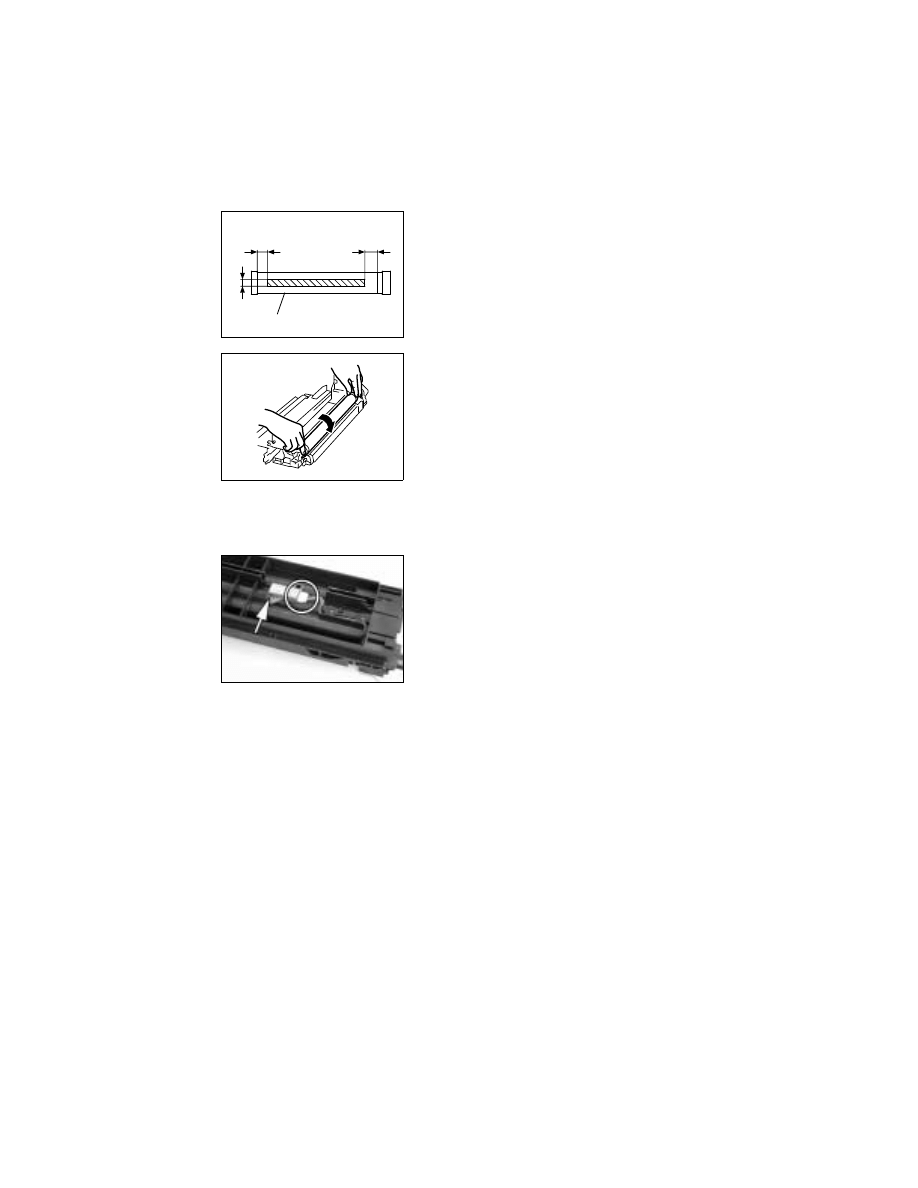
D-35
(4)
Replacement of the ATDC Sensor
1. Divide the IU into the Cleaning Assy and Developing Assy.
2. Remove the Developer Scattering Prevention Plate and dump developer.
4. Install the ATDC Sensor.
5. Pour developer.
6. Reinstall the Developer Scattering Prevention Plate.
7. Mount the Cleaning Assy to the Developing Assy.
8. Install the IU in the copier and run F8 operation.
9. Enter the adjustment value on the Adjust Label.
<<Area to which toner is to be applied>>
4021U057AA
20
-
3
0
mm
10 - 15 mm
20 - 25 mm
PC Drum
3. Hold both ends of the PC Drum with your both
hands and turn the PC Drum a half turn in the
direction of the arrow.
4021U009AA
3. Unplug one connector, and remove one screw
and the ATDC Sensor.
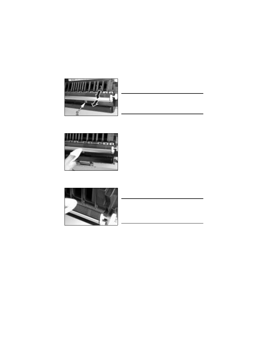
D-36
3-8.
IMAGE TRANSFER SECTION
(1)
Removal of the Image Transfer Roller Assy
1. Open the Right Door.
(2)
Cleaning of the Pre-Image Transfer Lower Guide Plate
1. Open the Right Door.
(3)
Cleaning of the Charge Neutralizing Plate
1. Open the Right Door.
2. Loosen one fixing bracket mounting screw.
3. Turn to remove the Pre-Image Transfer Upper
Guide Plate.
NOTE
• When reinstalling the fixing bracket, make sure
that the hook of the fixing bracket fits into the slot in
the Pre-Image Transfer Upper Guide Plate.
2. Using a soft cloth dampened with alcohol, wipe
the Pre-Image Transfer Lower Guide Plate clean
of dirt.
2. Using a soft cloth dampened with alcohol, wipe
the Charge Neutralizing Plate clean of dirt.
NOTE
• Use care not to allow the Image Transfer Roller to
be touched with alcohol.
• Do not allow the soft cloth to be caught by the tip of
the Charge Neutralizing Plate.
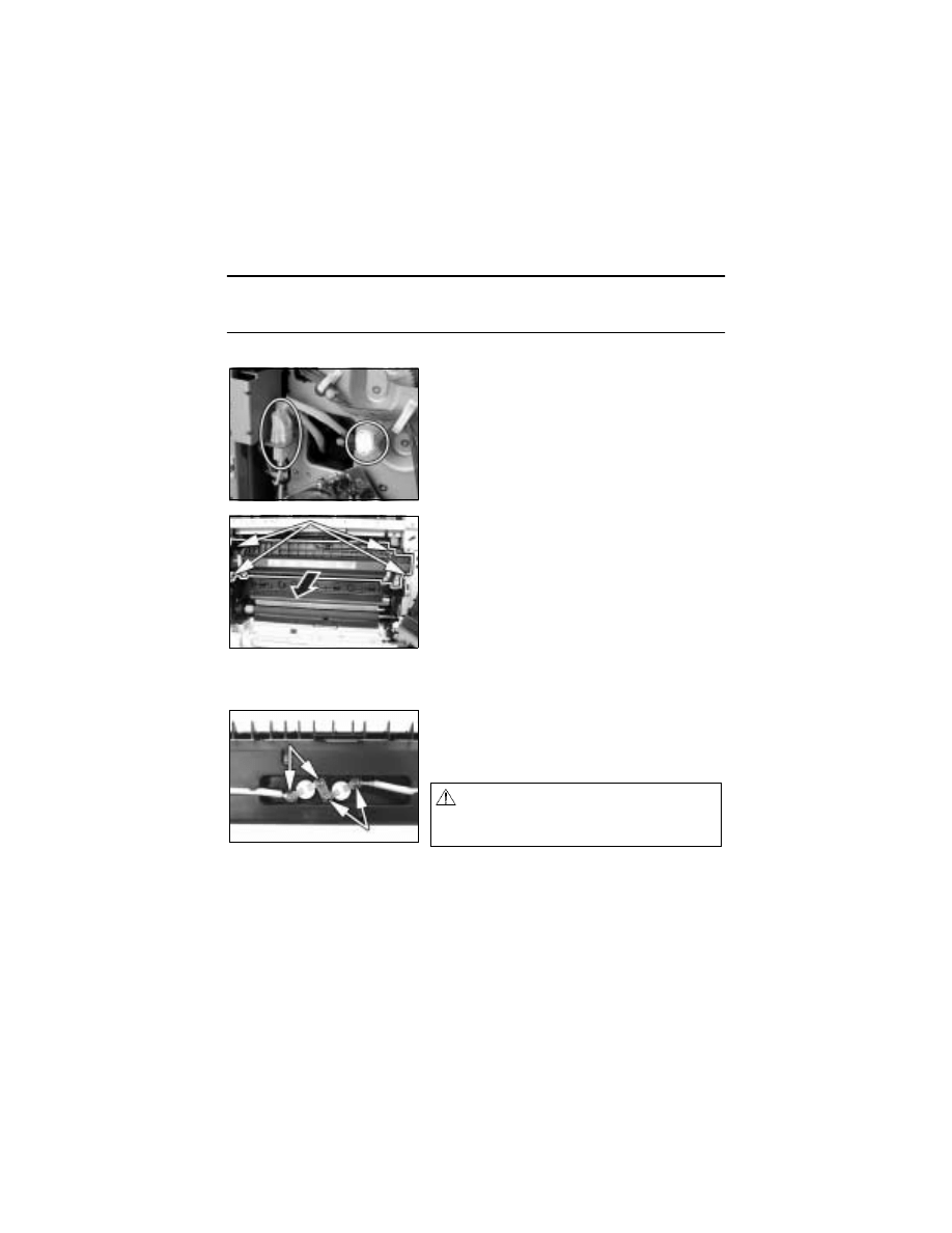
D-37
3-9.
FUSING SECTION
(1)
Removal of the Fusing Unit
1. Remove the control panel.
NOTE
• In this step, free the control panel without removing one flat cable and two ground wires
and unplugging one connector.
2. Remove the Front Cover, Rear Cover, and Rear Right Cover.
(2)
Disassembly of the Fusing Unit
<Removal of the Thermoswitch>
3. Unplug two connectors of the Fusing Unit.
4. Open the Right Door.
5. Remove four screws and the Fusing Unit.
1. For removal of per thermoswitch, remove two
screws.
✽
Although there are two thermoswitches actually,
the process of removal is same.
This is an Essential Safty Part.
(P/N: SP00-0130)
NOTE
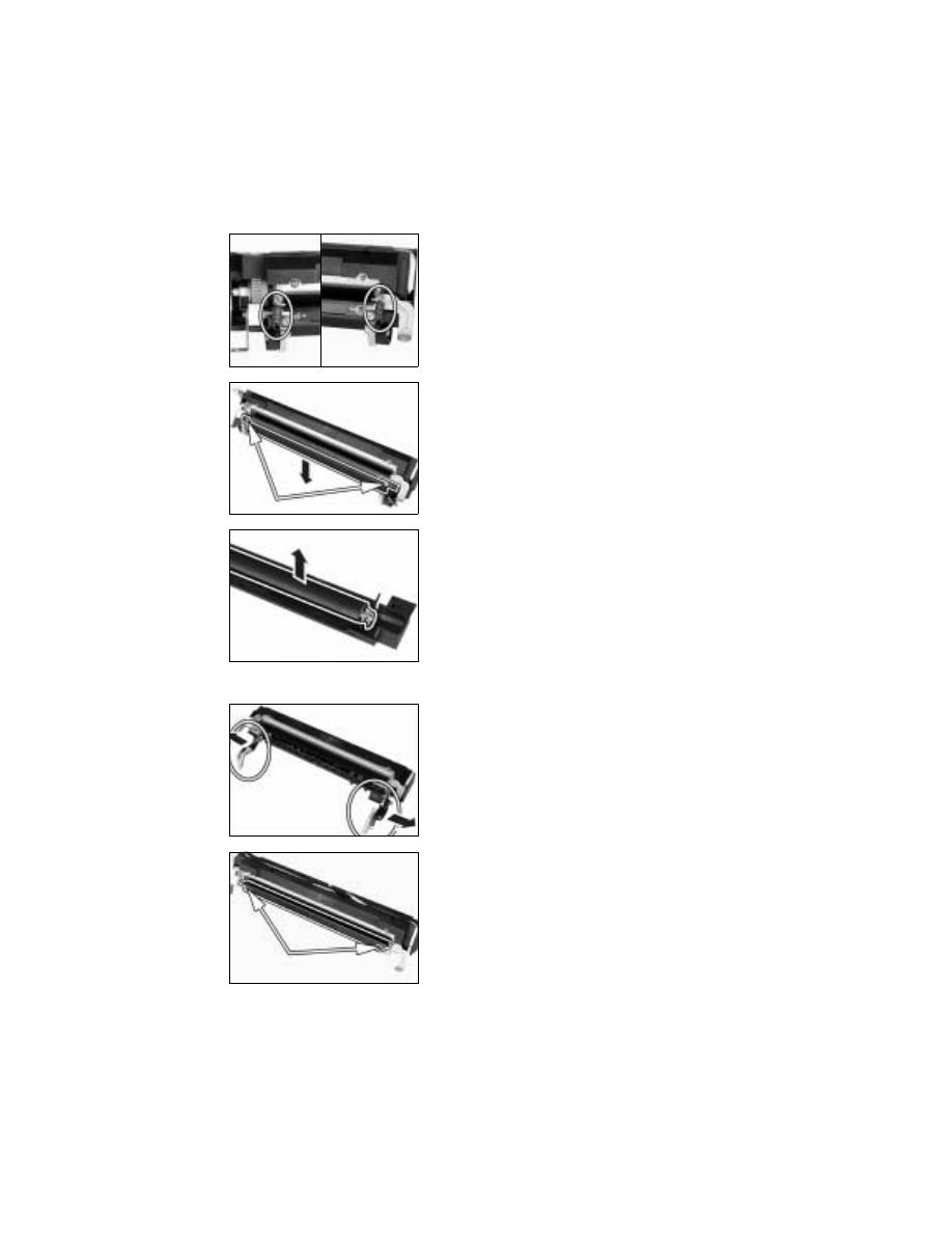
D-38
<Removal of the Right Fusing Roller>
<Removal of the Fusing Heater Lamp>
2. Unhook the pressure springs at the front and
rear.
3. Remove two shoulder screws, two washers, and
the Right Roller Assy.
4. Remove the Right Roller.
5. Remove the Pressure Lever Assemblies at the
front and rear.
6. Remove two screws and the Fusing Entrance
Guide Plate.
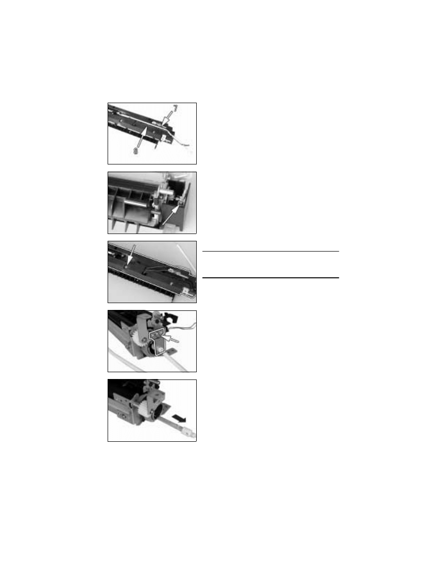
D-39
7. Remove the harness in the rear of the Heater
Lamp from the cover.
8. Remove the thermistor harness from the cover.
9. Remove one mounting screw from the front of the
Heater Lamp.
10. Remove one screw and the cover.
NOTE
• When reinstalling the cover, allow two tabs on the
cover to be caught in the frame.
11. Remove one screw and the rear lamp holder.
12. Remove the Fusing Heater Lamp.
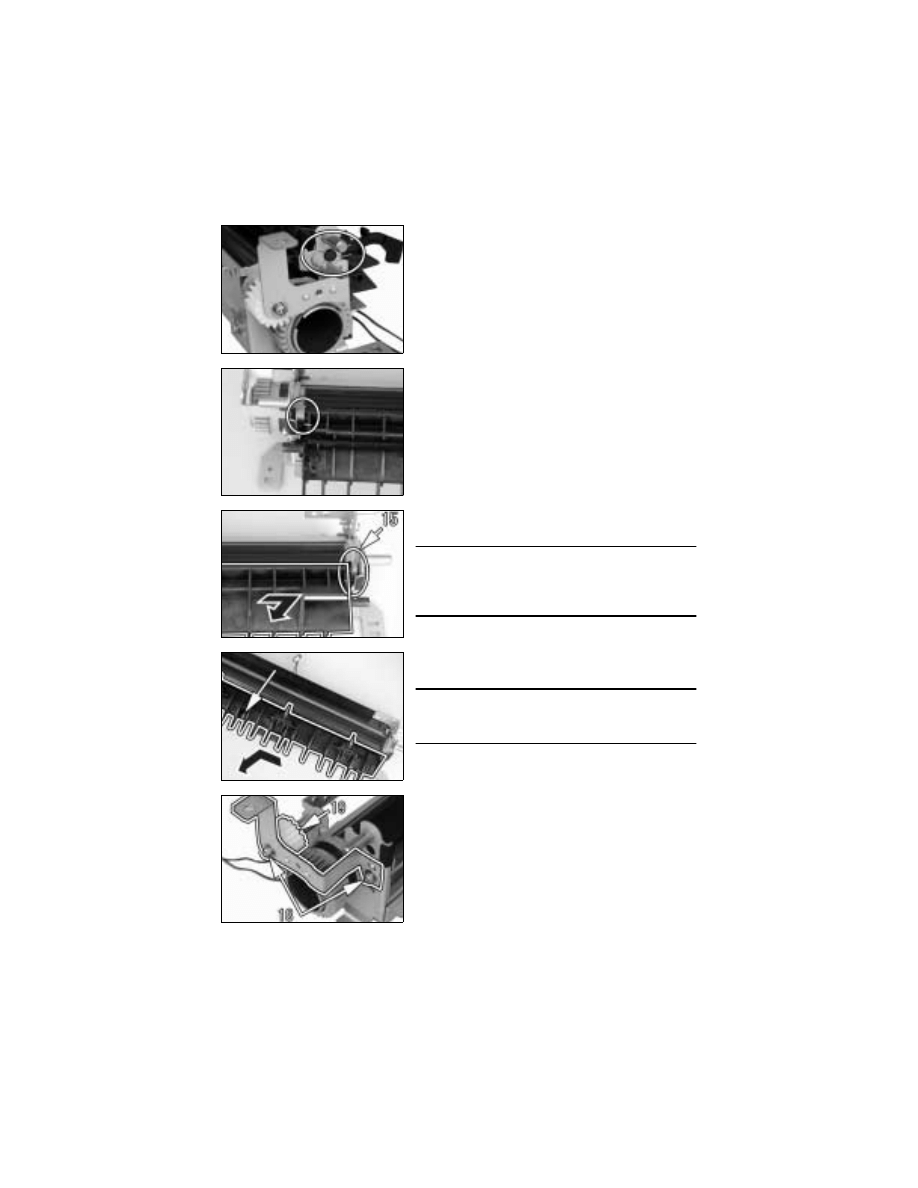
D-40
<Left Fusing Roller>
13. Snap off one retaining ring.
14. Unhook the spring in the rear of the Guide Assy.
15. Unhook the spring at the front of the Guide Assy.
16. Remove the Guide Assy.
NOTE
• When removing and reinstalling the Guide Assy,
use care not to allow the sensor lever spring to be
unhooked.
17. Remove one screw and the Paper Separator Fin-
ger Assy.
NOTE
• When reinstalling the Paper Separator Finger
Assy, allow six tabs to be caught in the frame.
18. Remove two screws and the mounting bracket.
19. Remove the idle gear.
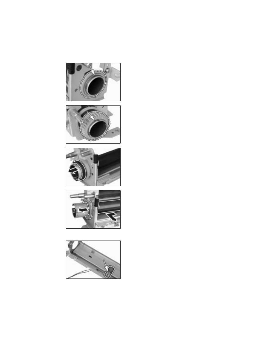
D-41
<Thermistor>
20. Snap off the retaining ring at the front of the Left
Fusing Roller and remove the washer and bush-
ing.
21. Snap off the retaining ring in the rear of the Left
Fusing Roller and remove the gear.
22. Remove the collar.
23. Remove the bushing.
24. Remove the Left Fusing Roller.
25. Remove one screw and the Thermistor.
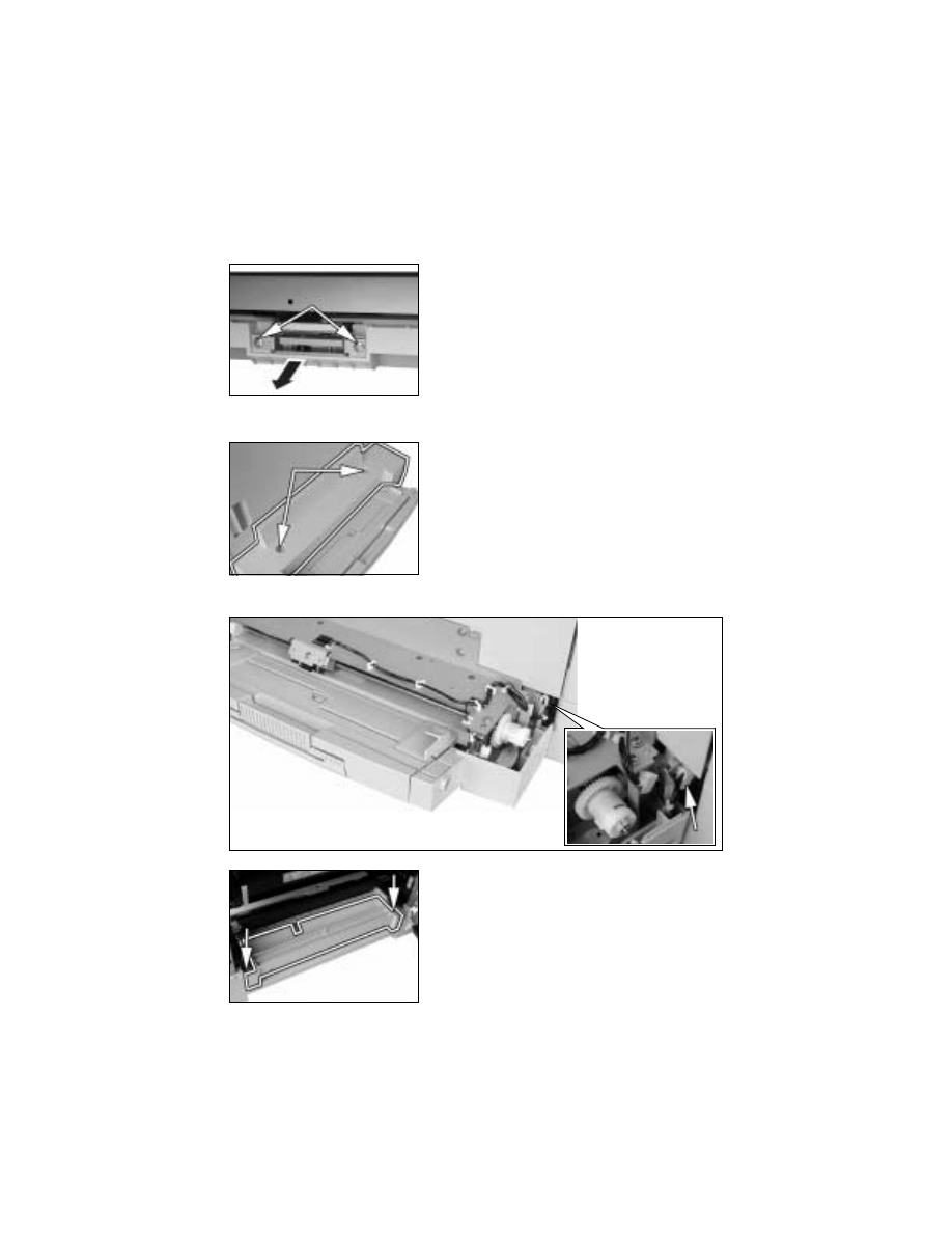
D-42
3-10.
MULTIPLE BYPASS (MT-102): OPTION
(1)
Removal of the Separator Roll Assy
(2)
Removal of the Paper Take-Up Roll
2. Remove the harness from one cord clamp.
1. Open the Right Door.
2. Remove two screws and the Separator Roll Assy.
1. Remove two screws and the cover.
3. Remove two screws and the Bypass Transport
Roller Assy.
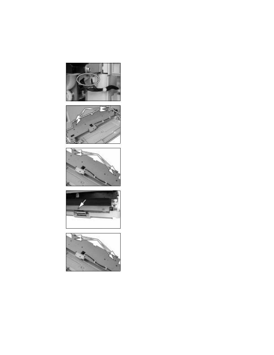
D-43
4. Unplug two connectors.
5. Remove four screws and the Multiple Bypass.
<<Multiple Bypass Installation Procedure>>
➀
Temporarily secure the Multiple Bypass using four
screws.
➁
Install the positioning pin at the location shown in
the illustration.
(Use the positioning pin furnished as an acces-
sory with the Multiple Bypass.)
➂
Close the Right Door and correctly position the
Multiple Bypass using the positioning pin.
➃
Tighten the four Multiple Bypass mounting screws
to specified torque.

D-44
6. Remove four screws and the Paper Take-Up
Assy.
7. Snap off one C-ring and remove the gear.
8. Snap off one C-ring.
9. Snap off one C-ring and remove the Paper Take-
Up Roll Assy.
10. Snap off one C-ring and remove the roll.
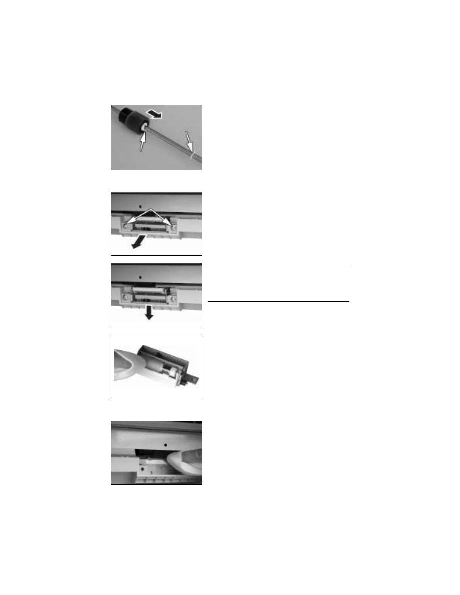
D-45
(3)
Cleaning of the Separator Roll/Paper Take-Up Roll
(4)
Cleaning of the Paper Take-Up Roll
11. Snap off one C-ring and one C-clip and remove
the paper Take-Up Roll.
1. Open the Right Door.
2. Remove two screws and the Separator Roll Assy.
NOTE
• When attempting to reinstall the Separator Roll
Assy, try to move the assy in the direction of the
arrow.
3. Using a soft cloth dampened with alcohol, wipe
the Separator Roll clean of dirt.
1. Open the Right Door.
2. Remove the Separator Roll Assy.
3. Using a soft cloth dampened with alcohol, wipe
the Paper Take-Up Roll clean of dirt.
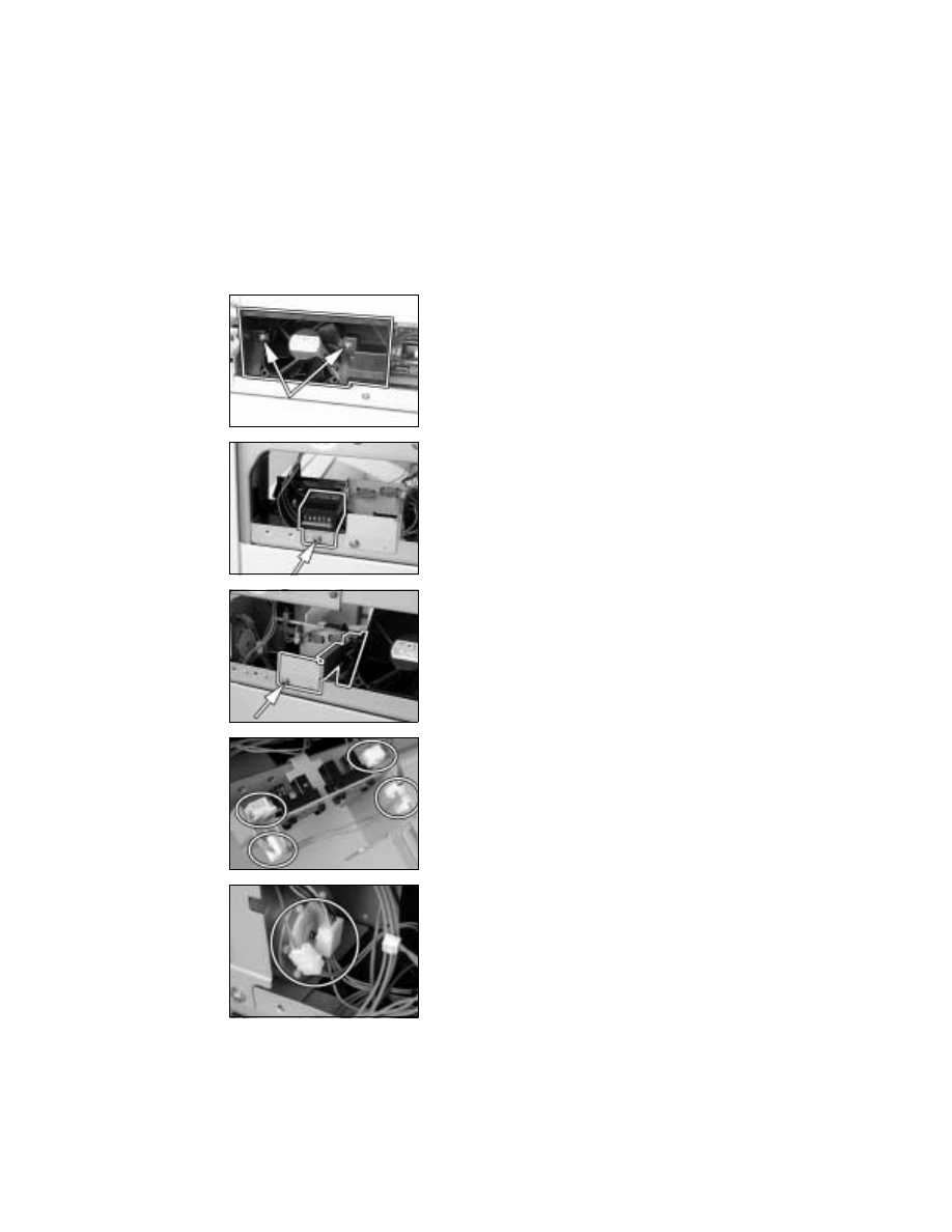
D-46
3-11.
JOB TRAY (IT-102): OPTION
(1)
Removal of the Main Board
1. Remove the control panel, Front Cover, Rear Cover, Right Cover, and Right Inside
Cover.
2. Remove two screws and the fan cover.
3. Remove one screw and the Total Counter (if the
copier is so equipped).
4. Remove one Sensor Assy mounting screw.
5. Unplug two connectors.
6. Remove the harness from two edge covers and
remove the Sensor Assy.
7. Unplug two connectors.
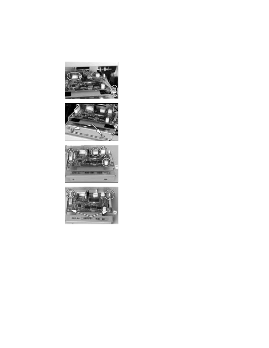
D-47
8. Unplug one connector and remove the harness
from one edge cover.
9. Remove two screws and the PWB Assy.
10. Unplug four connectors.
11. Remove two screws, two PWB Supports, and the
Main Board.
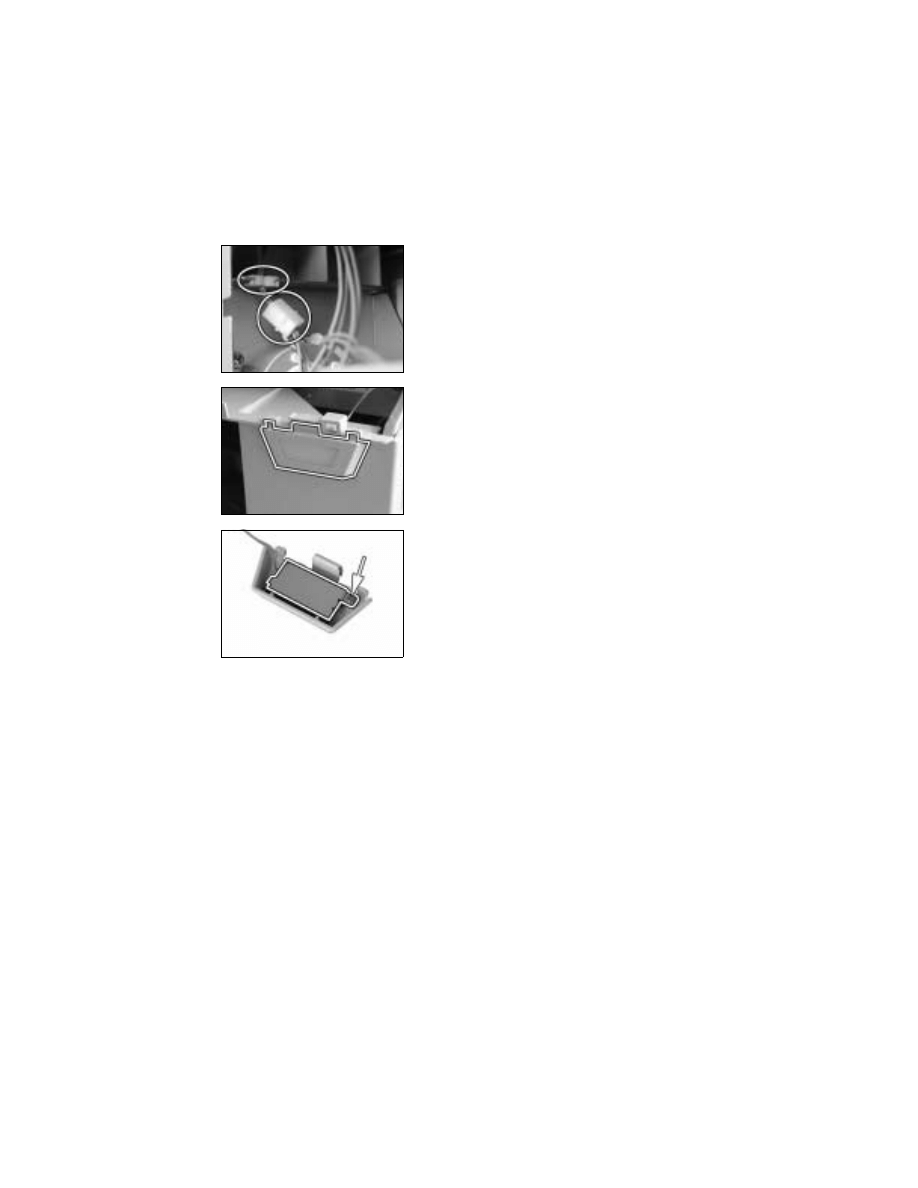
D-48
(2)
Paper Detecting Board
1. Remove the control panel, Rear Cover, and Right Cover.
2. Unplug one harness connector and remove the
harness from one edge cover.
3. Press the tabs to remove the Paper Detecting
Board Assy from the Front Cover.
4. Remove one screw and the Paper Detecting
Board.
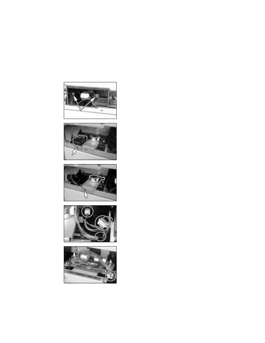
D-49
3-12.
SHIFTING UNIT (IS-101): OPTION
(1)
Removal of the Main Board
1. Remove the control panel, Front Cover, Rear Cover, Right Cover, and Right Inside
Cover.
2. Remove two screws and the fan cover.
3. Remove one screw and the Total Counter (if the
copier is so equipped).
4. Remove one screw and the Motor Assy.
5. Unplug two connectors and remove the harness
from the guide.
6. Unplug one connector from the Main Board.
7. Remove the harness from one edge cover.
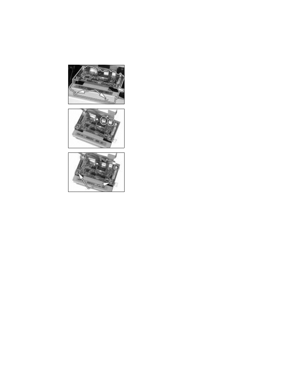
D-50
8. Remove two screws and the Main Board Assy.
9. Unplug two connectors.
10. Remove two screws, two PWB Supports, and the
Main Board.
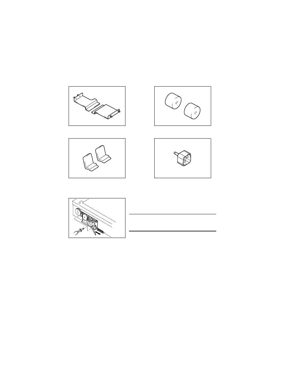
D-51
4.
ADJUSTMENT
4-1.
ADJUSTMENT JIGS AND TOOLS USED
<Scanner/Mirrors Carriage Positioning Jigs>
<Ds Collar Positioning Jigs>
<Db Gap Adjusting Jigs>
<PC Positioning Jig>
4-2.
TIMING BELT TENSION ADJUSTMENT
<Scanner Motor Timing Belt Adjustment>
4022D010AA
4022D011AA
4022D012AA
4022D030AA
1. Loosen three screws and move the Scanner
Motor Assy to the right or left to give tension to
the spring.
NOTE
• Give tension to the spring with the pulley in correct
mesh with the timing belt.
2. Using a torque driver, tighten the screws to a
torque of 2 kg
⋅
cm.
4022D032AA

D-52
4-3.
ACCESSING THE FUNCTION, TECH. REP. CHOICE, AND
ADJUST MODE
(1)
Function Mode
1. Press the COUNTER.
2. Press the following keys in this order: STOP
→
0
→
0
→
STOP
→
0
→
1.
3. Enter the code number “1” from the KEYPAD.
4. Press the START.
(2)
Tech. Rep. Choice Mode
1. Press the COUNTER.
2. Press the following keys in this order: STOP
→
0
→
0
→
STOP
→
0
→
1.
3. Enter the code number “2” from the KEYPAD.
4. Press the START.
(3)
Adjust Mode
1. Press the COUNTER.
2. Press the following keys in this order: STOP
→
0
→
0
→
STOP
→
0
→
1.
3. Press the STOP and then the START.
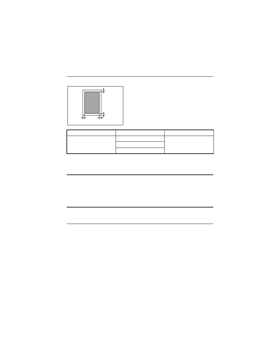
D-53
4-4.
ELECTRICAL/IMAGE ADJUSTMENT
(1)
Edge Erase Adjustment (Leading, Trailing, and Top/Bottom Edges)
Requirement
NOTE
• This adjustment is made when a request is made from the user to reduce the corre-
sponding erase width.
<Adjustment Procedure>
1. Enter the Tech. Rep. Choice mode.
2. With “c--” shown on the Display, enter the code number “5” from the KEYPAD and press
the START to enter the “Leading Edge Erase Adjustment” mode.
3. Press the CLEAR to clear the current setting value.
4. Enter the setting value from the KEYPAD and press the START to validate the entry.
Adjustment Instructions
To make the edge erase width smaller, decrease the setting value.
To make the edge erase width greater, increase the setting value.
5. Following the same procedure, set the erase width on the trailing edge and top/bottom
edge.
Mode
Code No.
Setting Range
Tech. Rep. Choice
5 (leading edge)
0 to 5, 1 step: 1 mm
6 (trailing edge)
7 (top/bottom)
• Adjust the erase width on the leading edge (width
A), trailing edge (width B), and the top/bottom edge
(width C).
✽
Default Setting: 4 mm
C
C
A
B
4022D503AA

D-54
(2)
Loop Length Adjustment (1st and 2nd Trays, Bypass Tray)
Requirement
• Adjust so that a loop of an adequate length is formed in the paper before the Synchroniz-
ing Roller as the paper is being fed through the copier.
NOTE
• This adjustment is made when the amount of leading edge void varies, or when paper
skews, is folded, or is misfed.
<Adjustment Procedure>
1. Enter the Tech. Rep. Choice mode.
2. With “c--” shown on the Display, enter the code number “8” from the KEYPAD and press
the START to enter the “Loop Length Adjustment (1st Tray)” mode.
3. Press the CLEAR to clear the current setting value.
4. Enter the setting value from the KEYPAD and press the START to validate the entry.
Adjustment Instructions
• Adjust by changing the setting value until the problems of variations in the amount of
leading edge void, paper skew, folded paper, and paper misfeed are eliminated.
5. Following the same procedure, adjust the loop length for the 2nd Tray and Bypass Tray.
Mode
Code No.
Setting Range
Tech. Rep. Choice
8 (1st Tray)
0 to 14,
1 step: Approx. 0.5 mm
9 (2nd - 5th Tray)
10 (Bypass Tray)
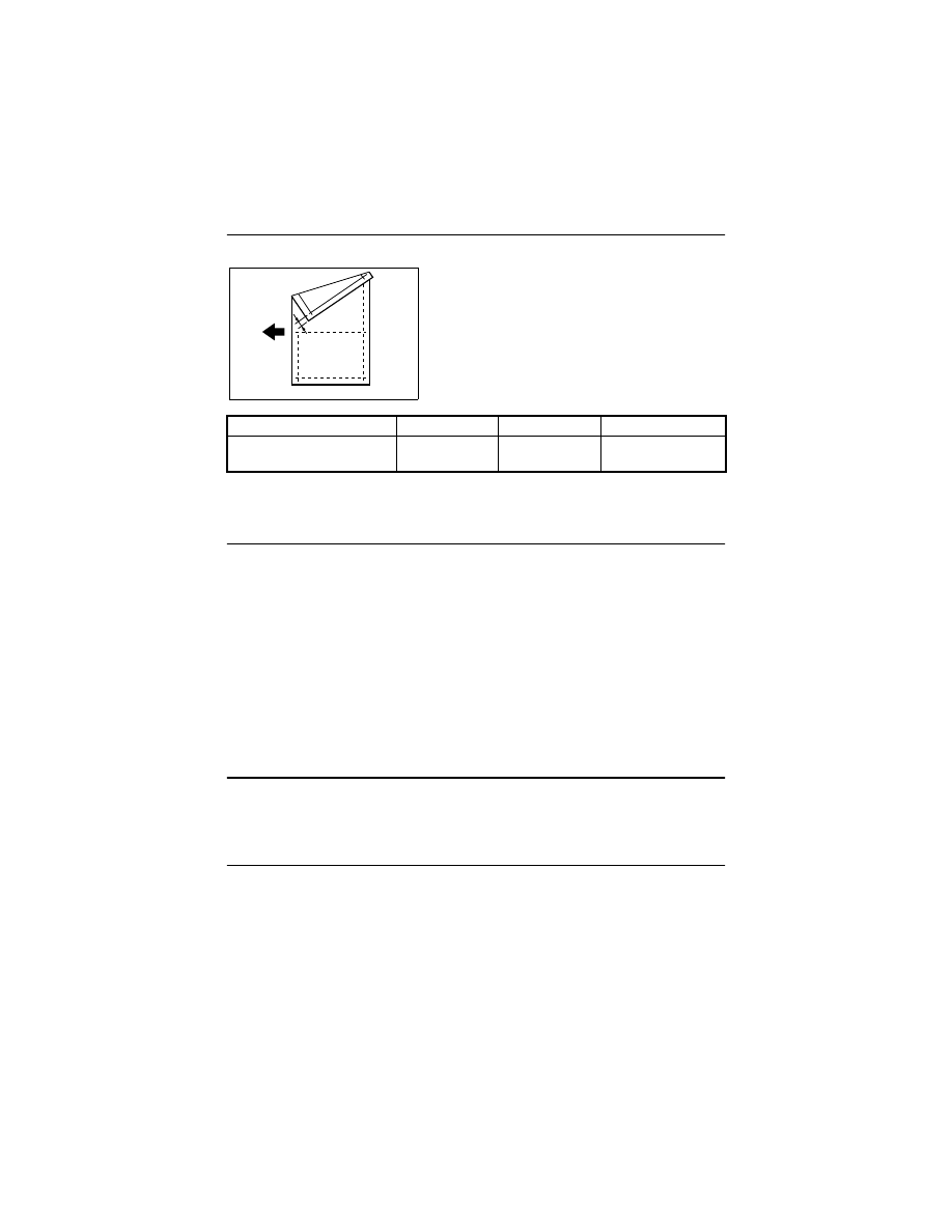
D-55
(3)
Printer CD Registration Adjustment
Requirement
NOTES
• This adjustment is made when the PH Unit has been replaced.
• Load the 1st Tray with A4 or 8-1/2
×
11 paper.
<Adjustment Procedure>
1. Enter the Adjust mode.
2. With “AJ-” shown on the Display, enter the code number “12” from the KEYPAD.
3. Press the PAPER SIZE to select the 1st Tray.
4. Press the START.
✽
Then, a test print will be produced.
5. Check to see if width A on the test print falls within the specified range.
If width A falls outside the specified range, perform the following steps to make an
adjustment.
6. With “AJ-” shown on the Display, enter the code number “1” from the KEYPAD and
press the START to enter the “Printer CD Registration Adjustment” mode.
7. Press the CLEAR to clear the current setting value.
8. Enter the new setting value from the KEYPAD and press the START to validate the
entry.
Adjustment Instructions
If width A on the test print is longer than the specifications, increase the setting value.
If width A on the test print is shorter than the specifications, decrease the setting value.
If a single adjustment procedure does not successfully bring width A into the specified
range, repeat steps 5 though 7.
Specifications
Mode
Code No.
Setting Range
A4: 20 ± 2.0 mm;
8-1/2
×
11: 11.2 ± 2.0 mm
Adjust
1
60 to 140,
1 step: 0.1 mm
• Adjust so that width A on the test print produced
falls within the specified range.
A
4686D504AA

D-56
(4)
Printer FD Registration Adjustment
Requirement
NOTES
• This adjustment is made when the PH Unit has been replaced.
• Load the 1st Tray with A4 or 8-1/2
×
11 paper.
<Adjustment Procedure>
1. Enter the Adjust mode.
2. With “AJ-” shown on the Display, enter the code number “12” from the Key Pad.
3. Press the PAPER SIZE to select the 1st Tray.
4. Press the START.
✽
Then, a test print will be produced.
5. Check to see if width B on the test print falls within the specified range.
If width B falls outside the specified range, perform the following steps to make an
adjustment.
6. With “AJ-” shown on the Display, enter the code number “2” from the KEYPAD and
press the START to enter the “Printer FD Registration Adjustment” mode.
7. Press the CLEAR to clear the current setting value.
8. Enter the new setting value from the KEYPAD and press the START to validate the
entry.
Adjustment Instructions
If width B on the test print is longer than the specifications, decrease the setting value.
If width B on the test print is shorter than the specifications, increase the setting value.
If a single adjustment procedure does not successfully bring width B into the specified
range, repeat steps 5 though 7.
Specifications
Mode
Code No.
Setting Range
10 ± 1.5 mm
Adjust
2
67 to 133, 1 step:
Approx. 0.19 mm
• Adjust so that width B on the test print produced
falls within the specified range.
B
4022D502AA

D-57
(5)
Scanner CD Registration Adjustment
Requirement
NOTES
• This adjustment is made when the PH Unit has been replaced and after “Printer Regis-
tration Adjustments (CD and FD)” and “Scanner Zoom Adjustment (CD).”
• This adjustment is made when the CCD Unit has been replaced and after “CCD Unit
Position Adjustment.”
• Load the 1st Tray with A4 or 8-1/2
×
11 paper.
<Adjustment Procedure>
1. Enter the Adjust mode.
2. With “AJ-” shown on the Display, enter the code number “12” from the KEYPAD.
3. Press the PAPER SIZE to select the 1st Tray.
4. Press the START.
✽
Then, a test print will be produced.
5. Place the test print produced on the Original Glass and make a copy of it.
6. Align the test print (original) with the copy and check for deviation.
If the deviation between width A on the test print and that on the copy falls outside the
specified range, perform the following steps to make an adjustment.
7. With “AJ-” shown on the Display, enter the code number “5” from the KEYPAD and
press the START to enter the “Scanner CD Registration Adjustment” mode.
8. Press the CLEAR to clear the current setting value.
9. Enter the new setting value from the KEYPAD and press the START.
Adjustment Instructions
If with A of the copy is longer than that on the test print, decrease the setting value.
If with A of the copy is shorter than that on the test print, increase the setting value.
If a single adjustment procedure does not successfully bring the deviation into the specified
range, repeat steps 6 though 8.
Specifications
Mode
Code No.
Setting Range
0 ± 2.0 mm
Adjust
5
20 to 180,
1 step: 0.1 mm
• Adjust so that the deviation between width A on the
test print and that on the copy falls within the spec-
ified range.
A
4686D504AA
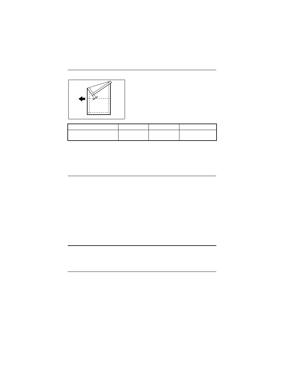
D-58
(6)
Scanner FD Registration Adjustment
Requirement
NOTES
• This adjustment is made when the PH Unit has been replaced and after “Printer Regis-
tration Adjustments (CD and FD)” and “Scanner Zoom Adjustment (CD).”
• This adjustment is made when the CCD Unit has been replaced and after “CCD Unit
Position Adjustment.”
• Load the 1st Tray with A4 or 8-1/2
×
11 paper.
<Adjustment Procedure>
1. Enter the Adjust mode.
2. With “AJ-” shown on the Display, enter the code number “12” from the KEYPAD.
3. Press the PAPER SIZE to select the 1st Tray.
4. Press the START.
✽
Then, a test print will be produced.
5. Place the test print produced on the Original Glass and make a copy of it.
6. Align the test print (original) with the copy and check for deviation.
If the deviation between width B on the test print and that on the copy falls outside the
specified range, perform the following steps to make an adjustment.
7. With “AJ-” shown on the Display, enter the code number “5” from the KEYPAD and
press the START to enter the 2Scanner CD Registration Adjustment” mode.
8. Press the CLEAR to clear the current setting value.
9. Enter the new setting value from the KEYPAD and press the START.
Adjustment Instructions
If with B of the copy is longer than that on the test print, increase the setting value.
If with B of the copy is shorter than that on the test print, decrease the setting value.
If a single adjustment procedure does not successfully bring the deviation into the specified
range, repeat steps 6 though 8.
Specifications
Mode
Code No.
Setting Range
0 ± 1.5 mm
Adjust
6
60 to 140,
1 step: 0.1 mm
• Adjust so that the deviation between width B on the
test print and that on the copy falls within the spec-
ified range.
B
4022D502AA
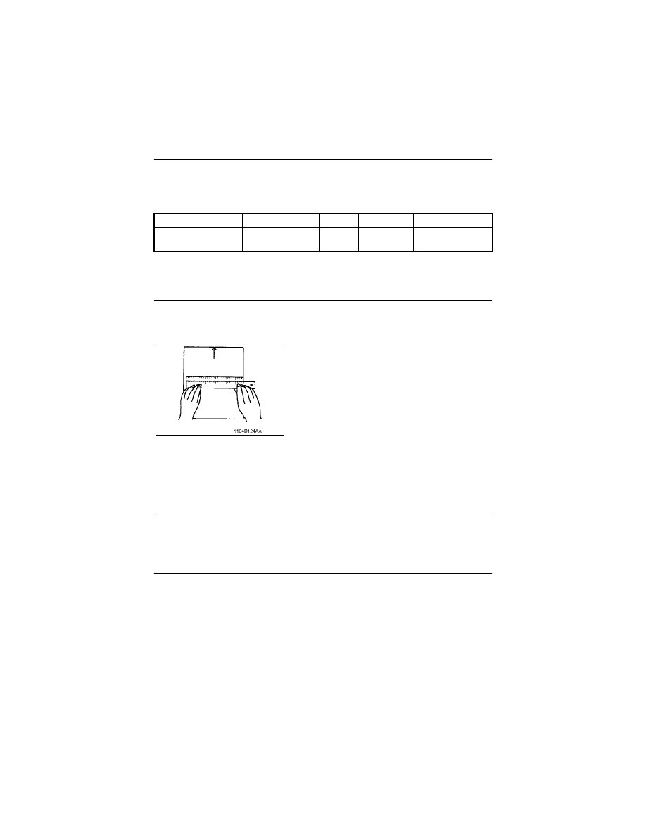
D-59
(7)
Scanner CD Zoom Adjustment
Requirement
• Adjust so that the amount of error falls within ±1.0 % of the length to be measured.
• Adjust so that the following specifications are met when the length of the scale is 200
mm.
NOTE
• This adjustment is made when the CCD Unit has been replaced and for fine-adjustment
after “CCD Unit Position Adjustment.”
<Adjustment Procedure>
1. Place a scale on the Original Glass in parallel with the Original Width Scale and make a
copy.
3. Enter the Adjust mode.
4. With “AJ-” shown on the Display, enter the code number “3” from the KEYPAD and
press the START to enter the “Scanner CD Zoom Adjustment” mode.
5. Press the CLEAR to clear the current setting value.
6. Enter the new setting value from the KEYPAD and press the START to validate the
entry.
Adjustment Instructions
If the length on the copy is longer than the actual one, decrease the setting value.
If the length on the copy is shorter than the actual one, increase the setting value.
If a single adjustment procedure does not successfully bring the amount of error into the
specified range, repeat steps 3 though 6.
Zoom Ratio
Specifications
Mode
Code No.
Setting Range
Full size (
×
1.00)
200 ± 2.0 mm
Adjust
3
97 to 103,
1 step: 0.4 %
2. Measure the length of the scale on the copy.
If the amount of error falls outside the specified
range, perform the following steps to make an
adjustment.
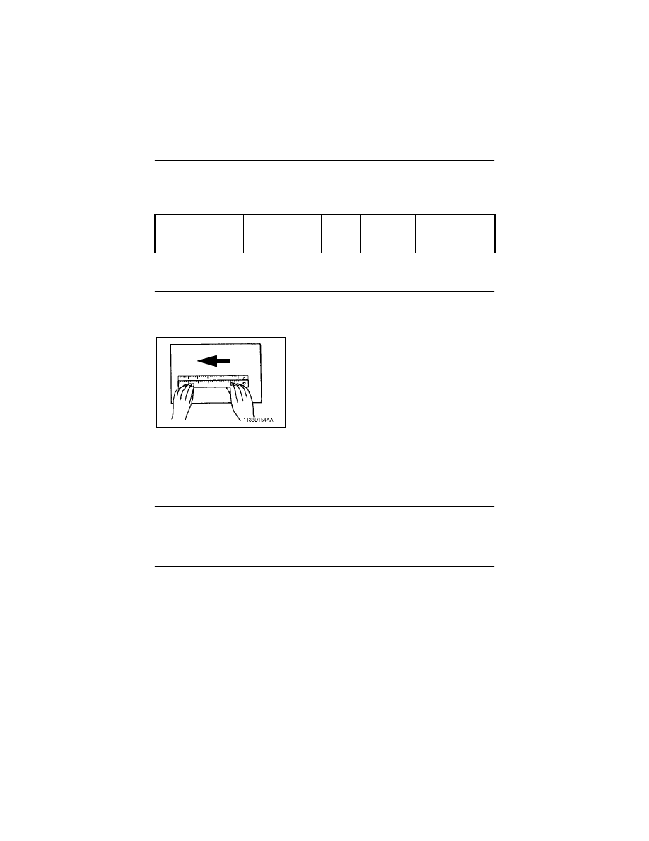
D-60
(8)
Scanner FD Zoom Adjustment
Requirement
• Adjust so that the amount of error falls within ±1.0 % of the length to be measured.
• Adjust so that the following specifications are met when the length of the scale is 300
mm.
NOTE
• This adjustment is made when the Scanner Drive Cables have been replaced.
<Adjustment Procedure>
1. Place a scale on the Original Glass in parallel with the Original Length Scale and make
a copy.
3. Enter the Adjust mode.
4. With “AJ-” shown on the Display, enter the code number “4” from the KEYPAD and
press the START to enter the “Scanner FD Zoom Adjustment” mode.
5. Press the CLEAR to clear the current setting value.
6. Enter the new setting value from the KEYPAD and press the START to validate the
entry.
Adjustment Instructions
If the length on the copy is longer than the actual one, decrease the setting value.
If the length on the copy is shorter than the actual one, increase the setting value.
If a single adjustment procedure does not successfully bring the amount of error into the
specified range, repeat steps 3 though 6.
Zoom Ratio
Specifications
Mode
Code No.
Setting Range
Full size (
×
1.00)
300 ± 3.0 mm
Adjust
4
97 to 103,
1 step: 0.4 %
2. Measure the length of the scale on the copy.
If the amount of error falls outside the specified
range, perform the following steps to make an
adjustment.
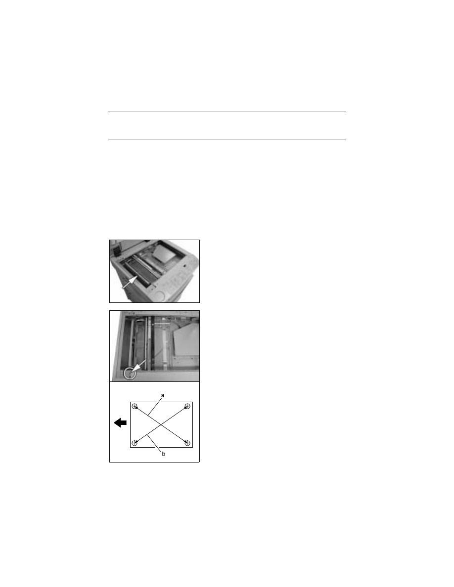
D-61
(9)
ATDC Sensor Automatic Adjustment (F8)
NOTES
• This adjustment is made when the developer has been replaced.
• Make this adjustment with the Toner Bottle removed from the copier.
<Adjustment Procedure>
1. Enter the Function mode.
2. With “F-” shown on the Display, enter the code number “8” from the KEYPAD to set the
copier into the “ATDC Sensor Automatic Adjustment” mode.
3. Press the START.
✽
This automatically runs the “ATDC Sensor Automatic Adjustment” sequence for about
three minutes.
4. After the F8 operation has been completed, check the adjustment value and enter it on
the Adjust Label.
(10) 2nd Mirrors Carriage Distortion Adjustment
1. Remove the ADF Glass.
2. Remove the Original Glass.
3. Move the 2nd Mirrors Carriage toward the adjust-
ment point as shown on the left.
4. Set precision (jeweller’s) screwdriver into the
adjusting hole and adjust the 2nd Mirrors Car-
riage Distortion Adjusting Screw.
<Adjustment Instructions>
✽
a<b: Turn the screw clockwise to raise the height.
✽
a>b: Turn the screw counterclockwise to lower the
height.
5. Install the Original Glass and make a copy to
check for images.
6. If there is a problem, repeat step 4.
7. Settle the 2nd Mirrors Carriage Height Adjusting
Screw with the paintlock.
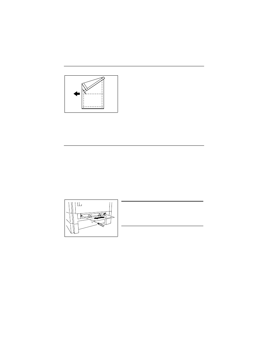
D-62
(11) Manual Bypass Registration Adjustment
Requirement
NOTES
• This adjustment is made when the PH Unit has been replaced and after “Printer Regis-
tration Adjustments (CD and FD)” and “Scanner Zoom Adjustment (CD).”
• This adjustment is made when the CCD Unit has been replaced and after “CCD Unit
Position Adjustment.”
• Load the 1st Tray with A4 paper.
<Adjustment Procedure>
1. Enter the Adjust mode.
2. With “AJ-” shown on the Display, enter the code number “12” from the KEYPAD.
3. Press the PAPER SIZE to select the 1st Tray.
4. Press the START.
✽
Then, a test print will be produced.
5. Place the test print produced on the Original Glass and make a copy using the Manual
Bypass Tray.
6. Align the test print (original) with the copy and check for deviation.
If the deviation between width A on the test print and that on the copy falls outside the
specified range, adjust the position of the Guide Plate Unit.
• Adjust so that the deviation between width A on the
test print and that on the copy falls within the spec-
ified range.
✽
Specifications: 0 ± 2.0 mm
A
4686D504AA
Adjustment Instructions
If with A of the copy is longer than that on the test
print, move the Guide Plate Unit to the rear.
If with A of the copy is shorter than that on the test
print, move the Guide Plate Unit to the front.
4022D033AA
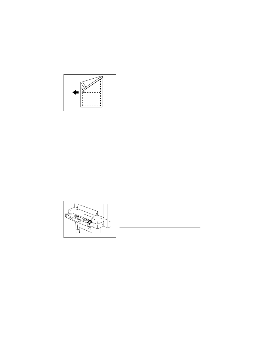
D-63
(12) Multiple Bypass Registration Adjustment (MT-102): Option
Requirement
NOTES
• This adjustment is made when the Multiple Bypass has been removed.
• This adjustment is made when the PH Unit has been replaced and after “Printer Regis-
tration Adjustments (CD and FD)” and “Scanner Zoom Adjustment (CD).”
• This adjustment is made when the CCD Unit has been replaced and after “CCD Unit
Position Adjustment.”
• Load the 1st Tray with A4 paper.
<Adjustment Procedure>
1. Enter the Adjust mode.
2. With “AJ-” shown on the Display, enter the code number “12” from the KEYPAD.
3. Press the PAPER SIZE to select the 1st Tray.
4. Press the START.
✽
Then, a test print will be produced.
5. Place the test print produced on the Original Glass and make a copy using the Multiple
Bypass Tray.
6. Align the test print (original) with the copy and check for deviation.
If the deviation between width A on the test print and that on the copy falls outside the
specified range, adjust the position of the Guide Plate Unit.
• Adjust so that the deviation between width A on the
test print and that on the copy falls within the spec-
ified range.
✽
Specifications: 0 ± 2.0 mm
A
4686D504AA
Adjustment Instructions
If with A of the copy is longer than that on the test
print, turn the adjusting screw counterclockwise.
If with A of the copy is shorter than that on the test
print, turn the adjusting screw clockwise.
4687U035AA
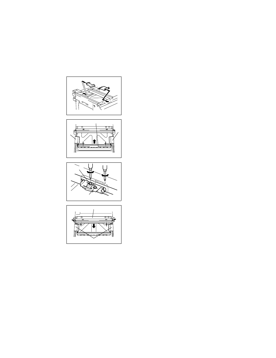
D-64
4-5.
OTHER ADJUSTMENTS
(1)
Adjustment of the Position of the Scanner and 2nd/3rd Mirrors Carriage
1. Fit the Scanner/Mirrors Carriage Positioning Jigs
in the space between the Scanner and the 2nd/
3rd Mirrors Carriage.
4022D013AA
Rear
2. Press the 2nd/3rd Mirrors Carriage tightly up
against the jigs.
4022D014AA
Re
a
r
2nd/3rd Mirrors Carriage
Jig
Jig
3. Loosen the set screw of the cable holding plate
and turn the adjusting screw as necessary to
eliminate clearance between the 2nd/3rd Mirrors
Carriage and the Scanner/Mirrors Carriage Posi-
tioning Jigs.
4022D015AB
Adjusting
Screw
Fixing Screw
4. Press the Scanner tightly up against the jigs and
tighten the set screw of the cable holding plate to
the specified torque.
4022D016AA
Scanner
Jigs
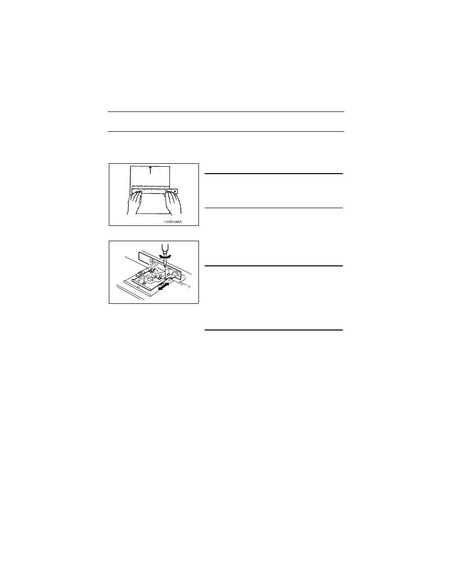
D-65
(2)
CCD Unit Position Adjustment
NOTE
• This adjustment is made when the CCD Unit has been replaced.
<Adjustment Procedure>
1. Place a scale on the Original Glass in parallel with the Original Width Scale and make a
copy.
2. Measure the length of the scale on the copy.
Requirement
• In compliance with “Scanner CD Zoom Adjust-
ment.”
☞
D-59
✽
If the measured value falls outside the specified
range, perform the following step to make an
adjustment.
3. Loosen three CCD Unit mounting screws, slide
the CCD Unit to the right or left, and secure it in
position.
Adjustment Instructions
If the length on the copy is longer than the actual
one, move the CCD Unit to the right.
If the length on the copy is shorter than the actual
one, move the CCD Unit to the left.
If a single adjustment procedure does not success-
fully bring the amount of error into the specified
range, repeat the steps.
4022D017AB
Left
Right
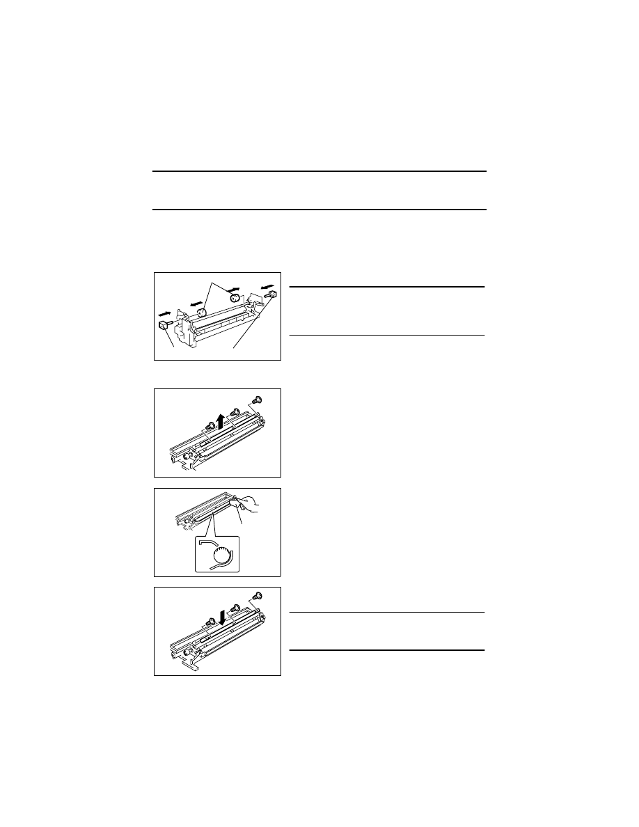
D-66
(3)
Adjustment of the Gap between the Doctor Blade and Sleeve Roller (Db Adjust-
ment)
Requirement
• The gap between the Doctor Blade and the Sleeve Roller should be 0.39 ± 0.04 mm (as
set using the jigs).
<Adjustment Procedure>
1. Remove the IU.
2. Separate the Cleaning Assy from the Developing Assy.
3. Remove the PC Drum, Main Erase, PC Drum Charge Corona Assy, and Ozone Filter.
5. Remove three screws and the Developer Scattering Prevention Plate.
4. Install the Ds Collar Positioning Jigs.
NOTE
• Ready a PC Positioning Jig (Pivot Shaft) sepa-
rately. (It can be ordered. For details, see the
Parts Manual.)
4022D018AC
Ds Collar Positioning Jigs
PC Positioning Jig
6. Remove three screws and the Doctor Blade.
4022D019AA
7. Using a small piece of paper, remove developer
from the shaded area on the surface of the
Sleeve Roller and put it in the Developer Mixing
Chamber.
8. Vacuum the developer left on the Sleeve Roller.
4022D036AA
Piece of paper
9. Temporarily secure the Doctor Blade using three
new screws.
NOTE
• Whenever a Db adjustment is made, use new
screws (to which lock paint has been applied).
4022D020AA
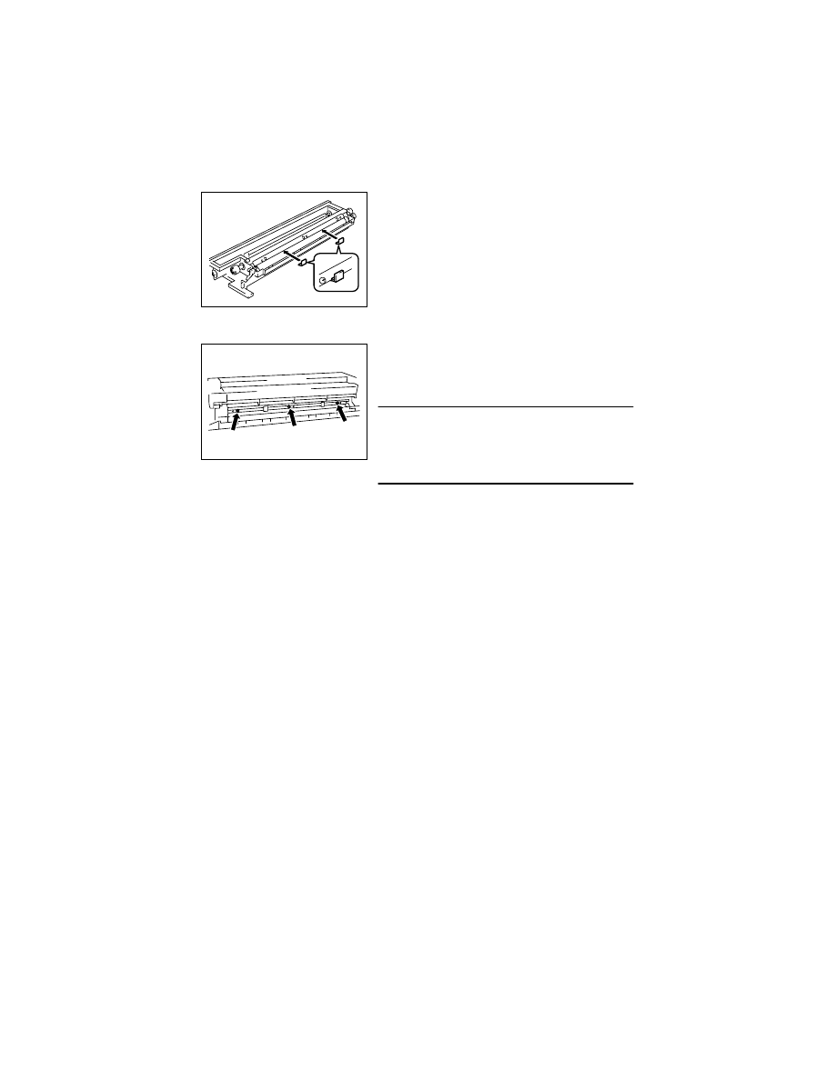
D-67
11. Put the Developing Assy and Cleaning Assy together.
10. Install the Db Gap Adjusting Jigs in a space
between the Sleeve Roller and Doctor Blade.
4022D021AB
12. Press the Doctor Blade tightly up against the Db
Gap Adjusting Jigs and, keeping that position,
tighten the screws in the order of
➀
at the front,
➁
at the center, and
➂
in the rear.
NOTE
• The Doctor Blade mounting screws have been
coated with lock paint and the job must be com-
pleted within 30 min. It the job extends more than
that time, change the screws for new ones.
4022D022AB
➀
➁
➂
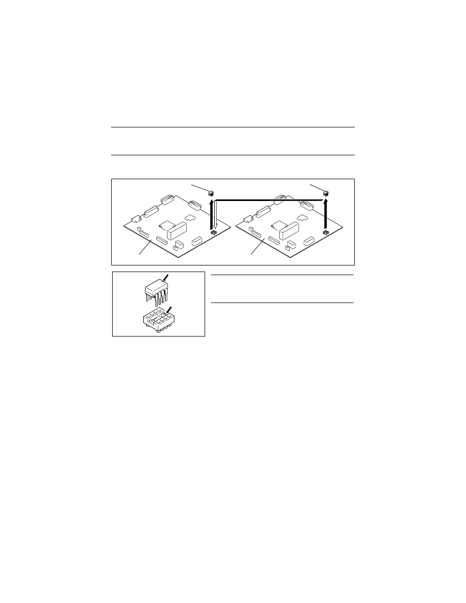
D-68
4-6.
MISCELLANEOUS
(1)
Remounting the EEPROM (U29)
NOTE
• When the Control Board (PWB-C) is replaced with a new one, EEPROM (U29) must be
demounted from the old PWB-C and remounted on the new PWB-C.
Remove the EEPROM (U29) from the new Control Board and mount the EEPROM (U29) of
the old Control Board to the new Control Board.
New EEPROM
Old EEPROM
New Control Board
Old Control Board
4022D031AA
NOTE
• Note the alignment notch marked with A on the
EEPROM (U29) when mounting the IC.
1171D049AA
A
A
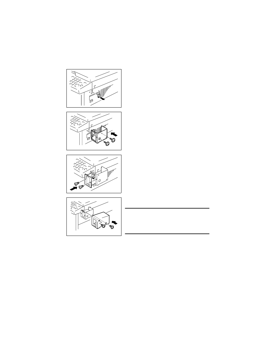
D-69
(2)
Installation of the Plug-In Counter Socket (Option)
1. Cut out the knockout from the Right Cover.
4021S010AA
2. Using two screws, secure the counter mounting
bracket.
4021D011AA
3. Connect the Plug-In Counter Socket connector.
4. Using two screws, secure the counter socket.
4021D012AA
5. Using two screws, secure the Plug-In Counter
cover.
NOTE
• When the Plug-In Counter Socket is mounted, set
“Plug-In Counter” of the Security mode to “1.” (For
details, see SWITCHES ON PWBs/TECH. REP.
SETTINGS.)
4021D013AA
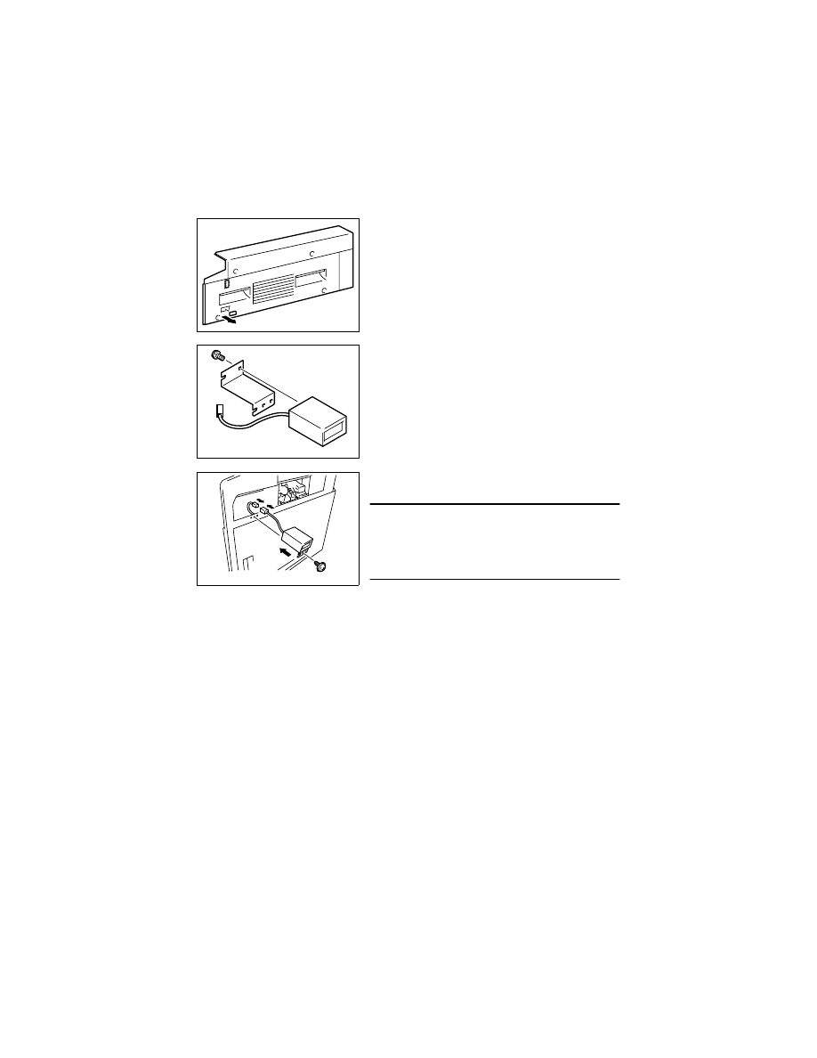
D-70
(3)
Installation of the Total Counter (Option)
1. Remove the control panel, Front Cover, Rear Cover, and Right Cover.
2. Cut out the knockout from the Right Cover.
4021D001AA
3. Using one screw, secure the Total Counter to its
mounting bracket.
4021D002AA
4. Connect the Total Counter connector.
5. Using one screw, secure the Counter Assy.
NOTE
• When the Total Counter is mounted, set “Mechani-
cal Total Counter” of the Security mode to “1.” (For
details, see SWITCHES ON PWBs/TECH. REP.
SETTINGS.)
4021D003AA

SWITCHES ON PWBs,
TECH. REP. SETTINGS

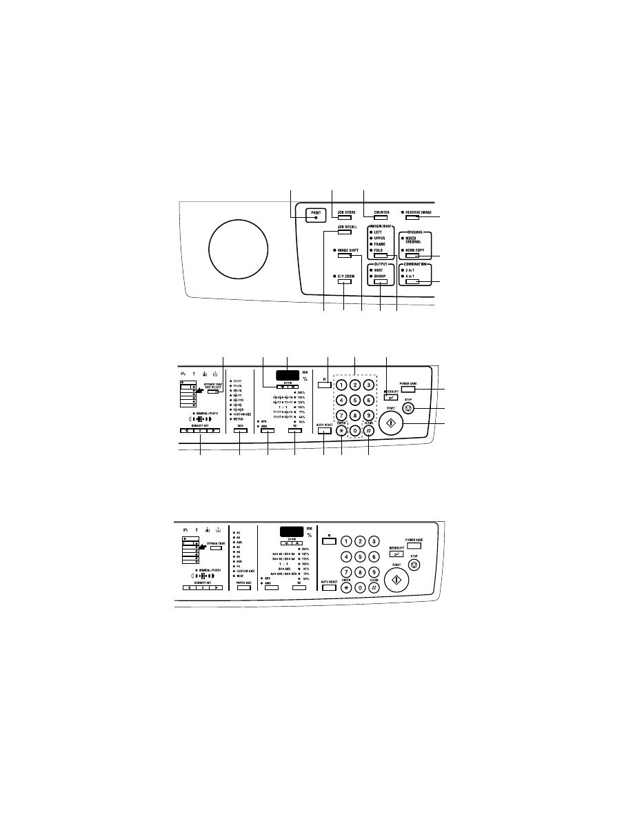
S-1
1.
CONTROL PANEL KEYS AND TOUCH PANEL
1-1.
Control Panel Keys
1
2
3
4
5
6
7
8
9
10
11
14
15
20
23
19
24
25
26
27
16
17
18
12
13
21
22
Metric area
Inch area
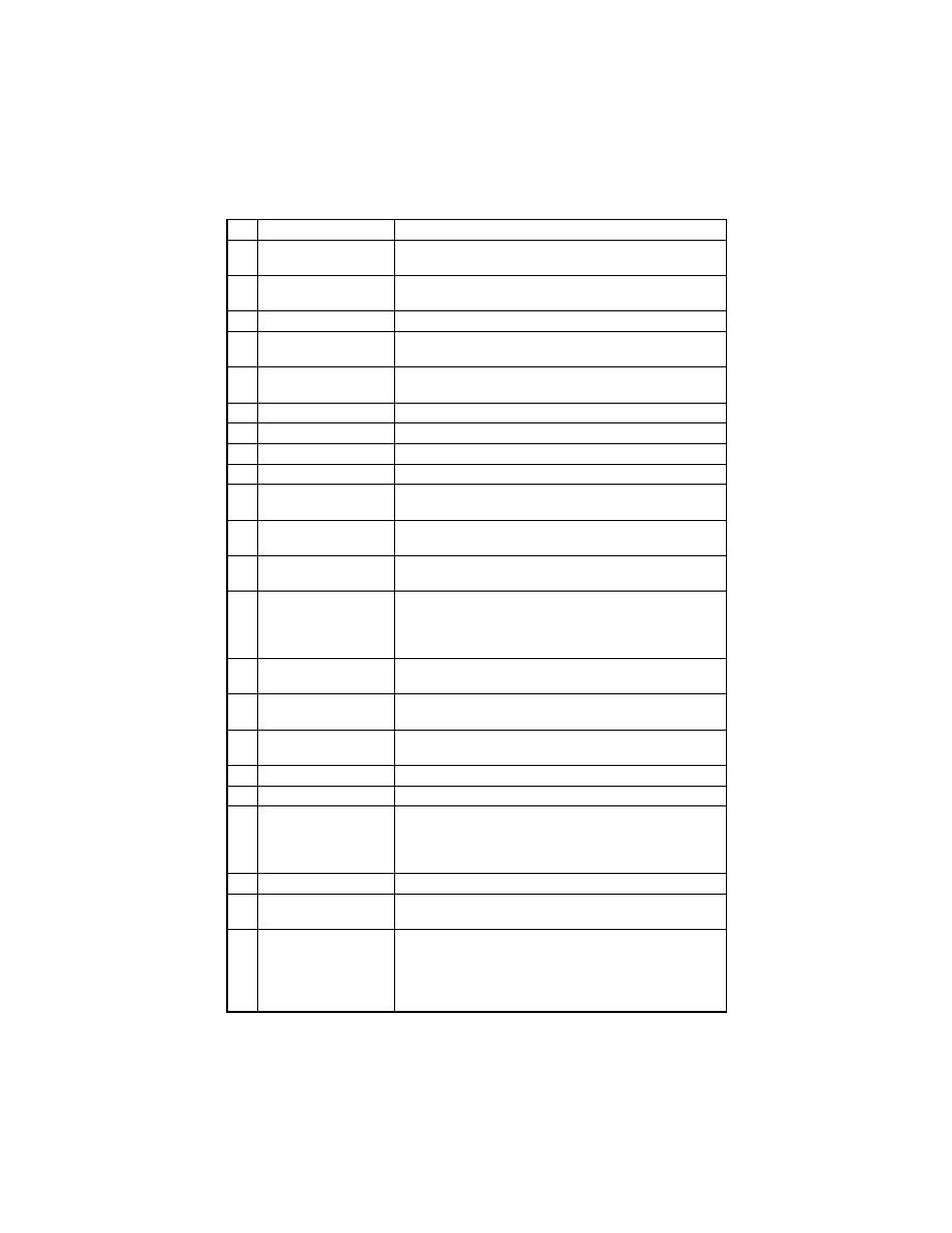
S-2
No.
Name
Description
1
Lit while data received from personal computer is being
printed
2
JOB STORE
Press to select the Job Input mode. Two different jobs can
be programmed.
3
COUNTER
Press to display the Total Counter or Size Counter value.
4
REVERSE IMAGE
Press to copy an original with the original total arrange-
ments reversed.
5
ORIGINAL
Press to select the Mixed Orig. or Book Separation func-
tion.
6
COMBINATION
Press to select the 2in1 or 4in1 function.
7
MARGINE ERASE
Press to select the erase position.
8
OUTPUT
Press to select the finishing function.
9
IMAGE SHIFT
Press to select the Image Shift mode.
10
X/Y ZOOM
Press to make a copy with different zoom ratios set for
X (horizontal) and Y (vertical) directions.
11
JOB RECALL
Press to recall either one of the two jobs previously stored
in memory.
12
BYPASS TRAY SIZE
SELECT
Press to select the size of the paper loaded in the Bypass
Tray.
13
ZOOM
• Press to change the zoom ratio in the range between
50 % and 200 % in 1 % increments.
• What is shown on the Display changes from the number
of copies to be made to the zoom ratio.
14
DISPLAY
Shows the number of copies to be made, the zoom ratio,
and other setting data.
15
KEYPAD
Use to type in the number of copies to be made and any
other numeric data.
16
ID
• Press when entering an account number.
• Becomes valid only when Copy Track has been set.
17
POWER SAVE
Press to set the copies into the Energy Saver mode.
18
INTERRUPT
Press to interrupt a copy job.
19
AUTO RESET
• Press to reset all copy functions and settings to their
defaults.
• Holding down the key for 3 seconds or more will set the
copies into the Utility mode.
20
CLEAR
Press to reset the number of copies to “1”.
21
STOP
• Press to stop a print cycle.
• Press to stop a scanning sequence.
22
START
• Press to start a scanning sequence.
• Press to start a print cycle.
• Press to validate the setting just made.
• The key lights up green when the copier is ready to make
copies, orange when it is not ready to make copies.

S-3
No.
Name
Description
23
ENTER
Press to validate the setting just made.
24
RE
Press to select a zoom ratio from among those fixed ratio
available as standard.
25
APS/AMS
Press to select either Auto Paper or Auto Size.
26
SIZE
Press to select the paper size.
27
DENSITY SET
Press to adjust the image density of the copy.
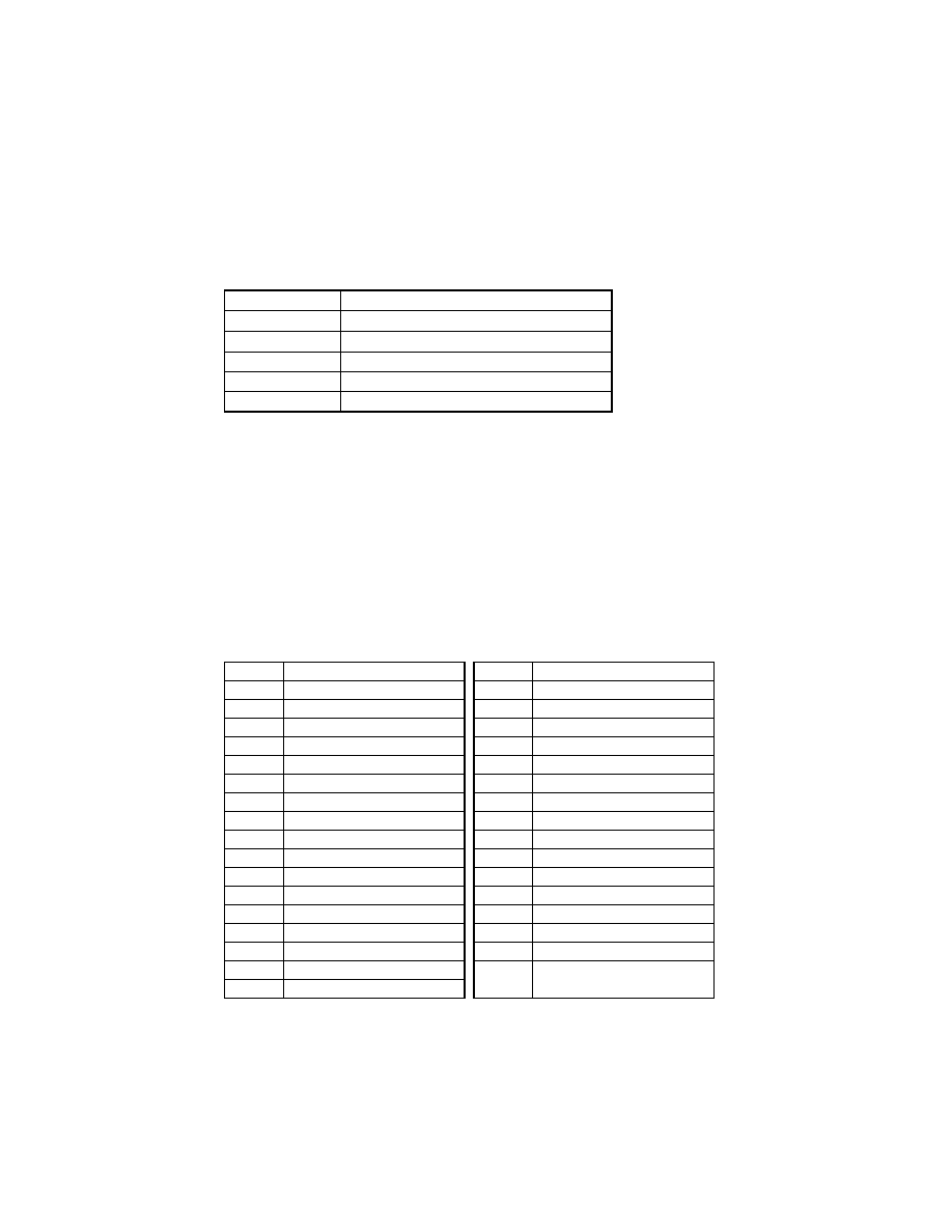
S-4
2.
UTILITY MODE
• Utility Mode is used to make various settings according to the user’s need.
2-1.
Settings in the Utility Mode
2-2.
Utility Mode Setting Procedure
<Procedure>
1. Hold down the AUTO RESET for 3 seconds.
2. Using the KEYPAD, enter the code corresponding to the desired subfunction.
Code No.: 1 to 5
3. Press the START.
<Exiting the Mode>
• Press the AUTO RESET.
(1)
User’s Choice Mode (Display: U-1)
• User’s Choice is used to make various settings according to the user’s need.
1. Settings in the User’s Choice Mode
Code No.
Description
U-1
User’s Choice Mode
U-2
Drum Dehumidify Mode
U-3
Toner Replenisher Mode
U-4
Custom Size Input Mode
U-5
Administrator Mode
Code No.
Function
Code No.
Function
C-1
Mixed Orig.
C18
Density (ADF)
C-2
Paper Priority
C19
Print Density
C-3
Copy Priority
C20
Paper Auto Detection (1st Tray)
C-4
Density Priority
C21
Paper Auto Detection (2nd Tray)
C-5
Density Level (Auto)
C22
Paper Auto Detection (3rd Tray)
C-6
Density Level (Manual)
C23
Paper Auto Detection (4th Tray)
C-7
Output Priority
C24
Paper Auto Detection (5th Tray)
C-8
Crisscross Mode
C25
Paper Size Detection (1st Tray)
C-9
4in1 Copy Order
C26
Paper Type (1st Tray)
C10
Book Binding Position
C27
Paper Type (Bypass Tray)
C11
Margin Setting
C28
Special Paper Setting (1st Tray)
C12
Erase Setting (Left)
C29
Special Paper Setting (2nd Tray)
C13
Erase Setting (Upper)
C30
Special Paper Setting (3rd Tray)
C14
Erase Setting (Frame)
C31
Special Paper Setting (4th Tray)
C15
Auto Panel Reset
C32
Special Paper Setting (5th Tray)
C16
Energy Saver
C33
Special Paper Setting
(Multiple Bypass Tray)
C17
Auto Shut OFF
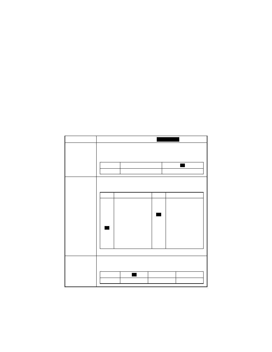
S-5
2. User’s Choice Mode Setting Procedure
<Procedure>
1. Hold down the AUTO RESET for 3 seconds.
2. Enter “1” from the KEYPAD. (Display: U-1)
3. Press the START.
4. Enter the corresponding code number from the KEYPAD.
5. Press the START. Then, the Display will show the current setting value.
6. Press the CLEAR to reset the current setting value.
7. Enter the new setting value from the KEYPAD.
8. Press the START. This will validate the new setting value just entered.
If any value outside the available setting range is entered, the Display shows “Err”
rejecting the entry. (The old setting value will reappear on the Display 1 sec. later.)
<Exiting the Mode>
• Press the AUTO RESET until the initial screen reappears.
3. Setting in the User’s Choice Mode
Code No.
Setting (The default is
).
C-1
<Mixed Orig.>
Select the priority Mixed Original Detection mode that is automatically
selected when the Power Switch is turned ON or AUTO RESET
pressed.
C-2
<Paper Priority>
Select the priority paper size or paper source that is automatically
selected when the copier is set into the Auto Size or Manual mode.
Initial setting: Metric area “6”/Inch area “15”
C-3
<Copy Priority>
Select the priority Auto mode (Auto Paper or Auto Size) selected
when the Power Switch is turned ON or AUTO RESET pressed.
Highlighted
Setting
0
Description
Mixed Orig. enabled
Mixed Orig. disabled
1
Setting
Description
Setting
Description
0
1
2
3
4
5
7
8
10
11
A3 (R)
B4 (R)
A4 (R)
B5 (R)
A5 (R)
F4 (R)
A4
B5
A5
11×17 (R)
11×14 (R)
12
13
14
16
20
21
22
23
24
25
8-1/2×14 (R)
8-1/2×11 (R)
5-1/2×8-1/2 (R)
11×8-1/2
8-1/2×5-1/2
1st Tray
2nd Tray
3rd Tray
4th Tray
5th Tray
Multiple Bypass Tray
6
15
Setting
1
2
Description
Auto paper
Auto Size
Manual
0
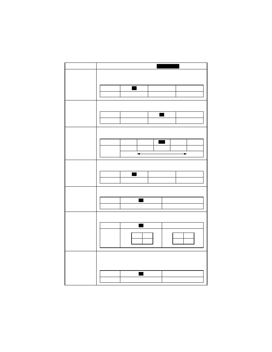
S-6
Code No.
Setting (The default is
).
C-4
<Density Priority>
Select the priority exposure mode selected when the Power Switch is
turned ON or AUTO RESET pressed.
C-5
<Density Level (Auto)>
Select the priority exposure level in the Auto Exposure mode.
C-6
<Density Level (Manual)>
Select the priority exposure level in the Manual Exposure mode.
C-7
<Output Priority>
Select the priority finishing type.
C-8
<Crisscross Mode>
Select whether to enable or disable crisscross sorting automatically
C-9
<4in1 Copy Order>
Specify the default copying order in the 4in1 mode.
C10
<Book Binding Position>
Select whether to the copier scan the left-hand-side page (Left-
bound) or the right-hand-side page (Right-bound) first when it scans
an open book.
Highlighted
Setting
1
2
Description
Auto
Manual
Photo Manual
0
Setting
0
2
Description
Lighter
Normal
Darker
1
Setting
1
2
4
5
Description
Step 1
Step 2
Step 3
Step 4
Step 5
Lighter
Darker
3
Setting
1
2
Description
Non-Sort
Sort
Group
0
Setting
1
Description
Enabled
Disabled
0
Setting
1
Description
0
1
2
3
4
1
3
2
4
Setting
1
Description
Left-bound
Right-bound
0
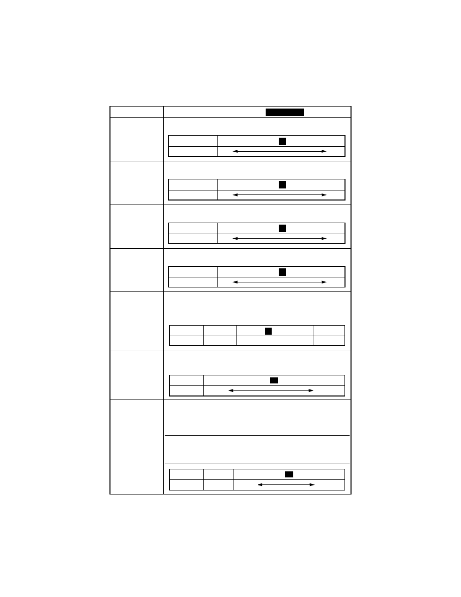
S-7
Code No.
Setting (The default is
).
C11
<Margin Setting>
Adjust the margin width for the File Margin copy.
C12
<Erase Setting (Left)>
Adjust the erase width for the Left Erase copy.
C13
<Erase Setting (Upper)>
Adjust the erase width for the Upper Erase copy.
C14
<Erase Setting (Frame)>
Adjust the erase width for the Frame Erase copy.
C15
<Auto Panel Reset>
Select the time it takes the Auto Panel Reset function, which resets
the panel settings when the set period of time elapses after a copy
cycle has been completed or the last key operated, to be activated.
C16
<Energy Saver>
Select the time it takes the copier to enter the Energy Saver mode
after a copy cycle has been completed or the last key operated.
C17
<Auto Shut OFF>
Select the time it takes the Auto Shut Off function, which shuts down
the copier when the set period of time elapses after a copy cycle has
been completed or the last key operated, to be activated.
Note:
• The option of “0” can be set if “Yes” is selected for “Disable Auto
Shut OFF” of the “Administrator Mode” function.
Highlighted
Setting
0 .................................
.......................... 20
Description (mm) 0
20
10
Setting
5 .................................
.......................... 20
Description (mm) 5
20
10
Setting
5 .................................
.......................... 20
Description (mm) 5
20
10
Setting
5 .................................
.......................... 20
Description (mm) 5
20
10
Setting
0
to 5
6
Description
30 sec.
1 min. to 5 min.
Disable
1
Setting
1 ...................................
................................ 240
Description 1 min.
240 min.
15
Setting
0
1...........................
.......................240
Description
Disabled 1 min.
240 min.
30
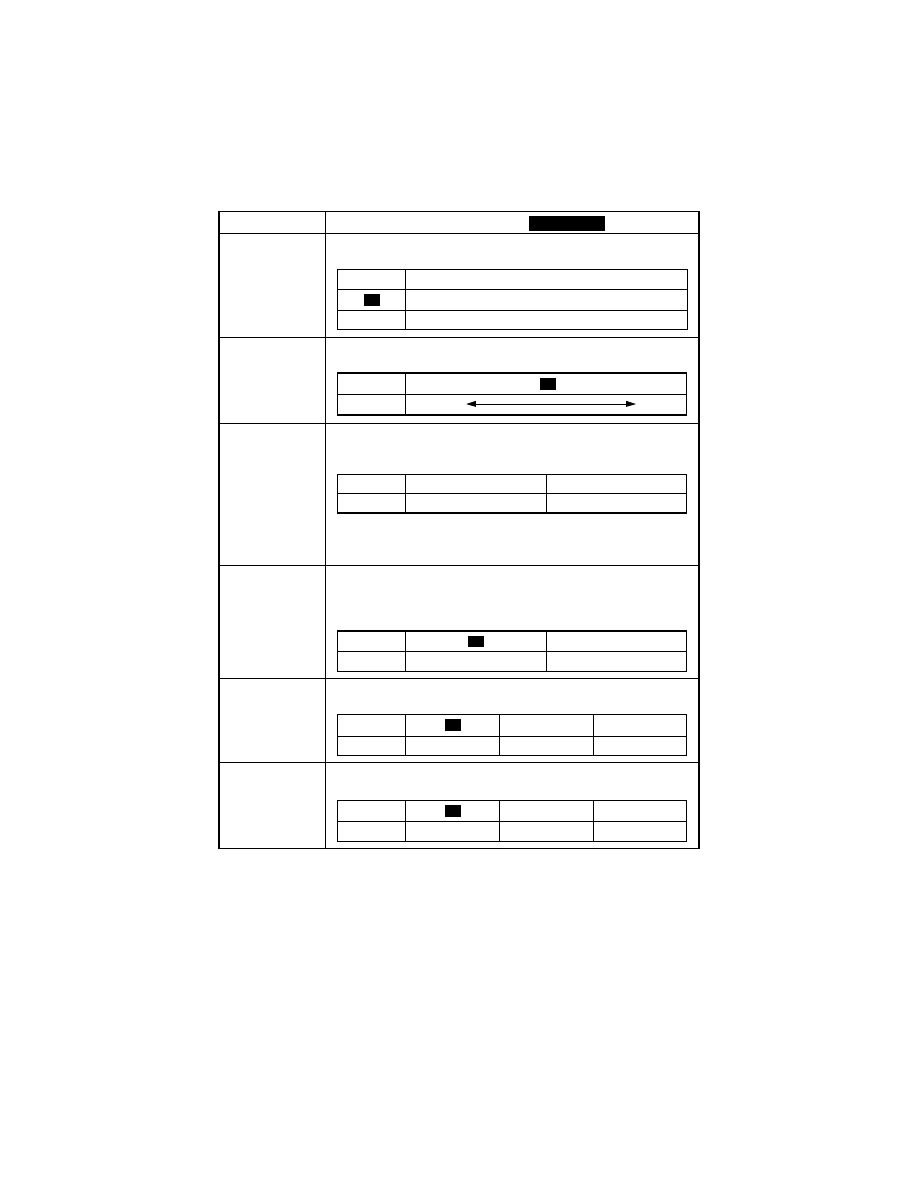
S-8
Code No.
Setting (The default is
).
C18
<Density ADF>
Adjust the copy image density level when the ADF is being used.
C19
<Priority Density>
Set the image density level for printing
C20 to 24
<Paper Auto Detection>
Select the system of measurement of the paper for automatic paper
size detection.
Initial setting: Metric area “1”/Inch area “0”
C20: 1st Tray C21: 2nd Tray C22: 3rd Tray
C23: 4th Tray C25: 5th Tray
C25
<Paper Size Detection>
Select the paper size detection method for the 1st Tray. If paper of a
nonstandard size is to be used, select “1.” Size input is made using
“U-4.”
C26
<Paper Type (1st Tray)>
Select the type of paper loaded in the 1st Tray.
C27
<Paper Type (Bypass Tray)>
Select the type of paper loaded in the Bypass Tray.
Highlighted
Setting
Description
When the standard original (text, etc.) is used.
1
To give better reproduction of faint original.
0
Setting
0 1 3 4
Description Lighter.
Darker
2
Setting
0
1
Description
Inch
Metric
Setting
1
Description
Automatic detection
Size input
0
Setting
1
2
Description
Plain Paper
Cards
OHP
0
Setting
1
2
Description
Plain Paper
Cards
OHP
0
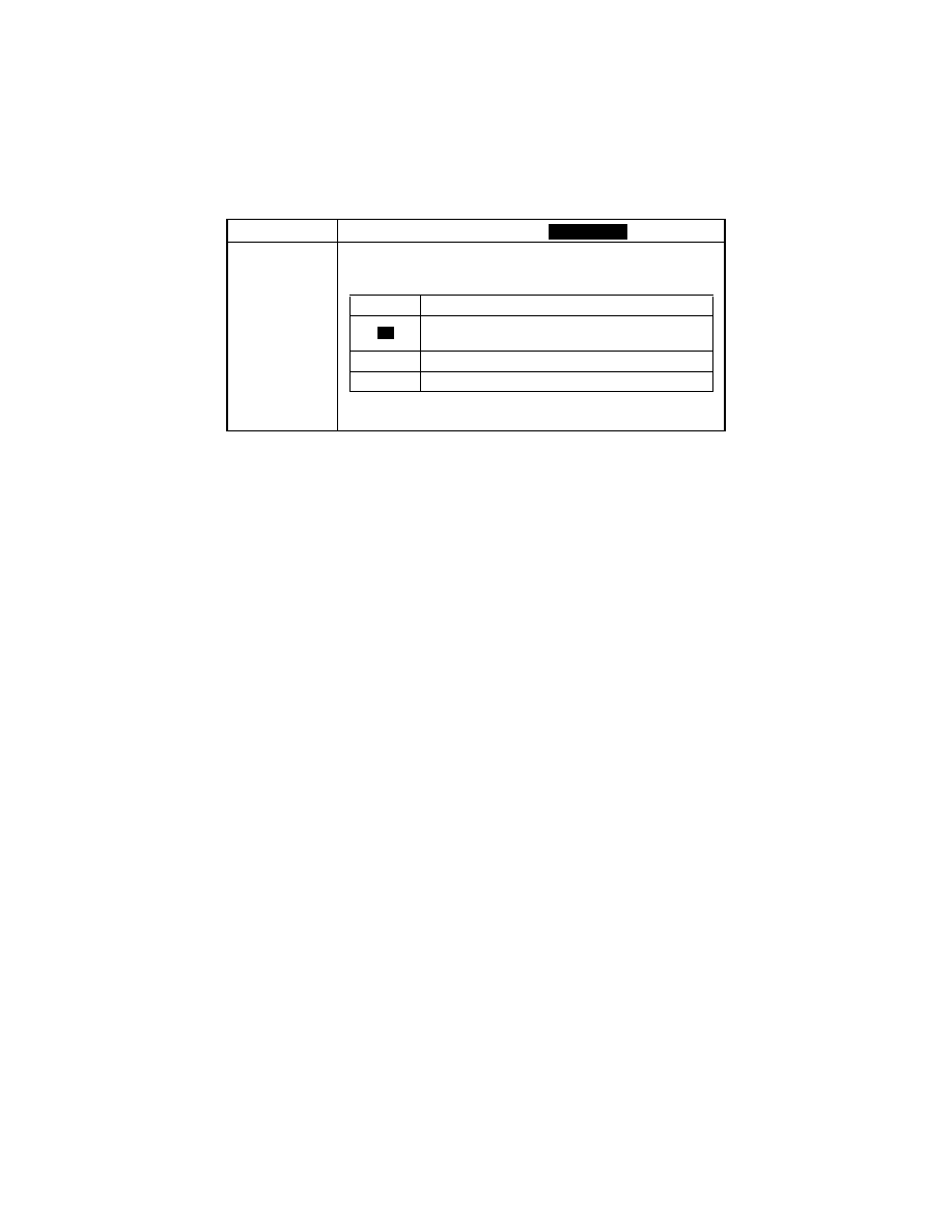
S-9
(2)
Drum Dehumidify Mode (Display: U-2)
• Removes dewdrops that have formed on the surface of the PC Drum.
<Procedure>
1. Hold down the AUTO RESET for 3 seconds.
2. Enter “2” from the KEYPAD. (Display: U-2)
3. Press the START. The Drum Dry sequence will be stopped after a given period of time.
(3)
Toner Replenisher Mode (Display: U-3)
• Supply of toner is replenished. The replenishing sequence is stopped after a given
period of time or when a required level of toner-to-carrier ratio is recovered.
<Procedure>
1. Hold down the AUTO RESET for 3 seconds.
2. Enter “3” from the KEYPAD. (Display: U-3)
3. Press the START.
(4)
Custom Size Input Mode (Display: U-4)
• Input the size of the paper loaded in the 1st Tray. (This is necessary when paper of a
nonstandard size is to be used.)
<Procedure>
1. Hold down the AUTO RESET for 3 seconds.
2. Enter “4” from the KEYPAD. (Display: U-4)
3. Press the START. Then, the Display will show the currently set value (in the FD direc-
tion).
4. Press the CLEAR to reset the currently set value.
5. Enter the new value from the KEYPAD.
6. Press the START. Then, the Display will show the currently set value (in the CD direc-
tion).
7. Press the CLEAR to reset the currently set value.
8. Enter the new value from the KEYPAD.
9. Press the START to validate the values entered.
✽
If a value entered falls outside the specified range (paper size), that entry is rejected and
the old value is restored.
<Exiting the Mode>
• Press the AUTO RESET.
Code No.
Setting (The default is
).
C28 to 33
<Special Paper Setting>
Allow Paper of same type to be fed from another tray when paper from
one source is empty.
C20: 1st Tray C21: 2nd Tray C22: 3rd Tray
C23: 4th Tray C25: 5th Tray
C23: Multiple Bypass Tray
Highlighted
Setting
Description
Enables Auto Paper (selection). Enables Auto Tray
Switching.
1
Disables Auto Paper. Enables Auto Tray Switching.
2
Disables Auto Paper. Disables Auto Tray Switching.
0

S-10
(5)
Administrator Mode (Display: U-5)
• The entry on the “Administrator No. Input” set using the Tech. Rep. Mode permits the set-
tings of the following functions.
1. Administrator Mode Function Setting Procedure
<Procedure>
1. Hold down the AUTO RESET for 3 seconds.
2. Enter “5” from the KEYPAD. (Display: U-5)
3. Press the START.
4. Enter the Administrator number from the KEYPAD.
5. Press the START. (Display: Ad )
✽
If a mismatch is detected of the administrator number, the Display shows “---.”
6. Enter the code assigned to the desired subfunction from the KEYPAD. (1 or 2)
7. Press the START.
<Exiting the Mode>
• Press the AUTO RESET until the initial screen reappears.
2. Administrator Mode Function Tree
U-5: Administrator
Mode
Ad1: Copy Track
Ad2: Disable Auto
Shut OFF
A-1: Copy Track
A-2: Input Account
A-3: Disable Account
A-4: Change Account
A-5: Total Counter Display
by Account
A-6: Total Counter Clear
for All Accounts
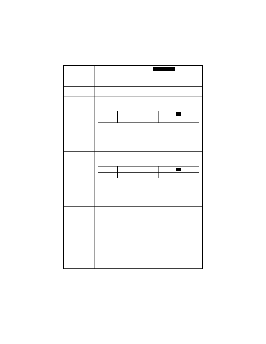
S-11
3. Setting in the Administrator Mode
Code No.
Setting (The default is
).
U-5
<Administrator Mode>
Allows for setting two functions, “Copy Track” and “Disable Auto Shut
OFF.”
Ad1
<Copy Track>
Allows for making the six different subfunctions.
Ad2
<Disable Auto Shut OFF>
Select whether to allow the option “0” to be select in User’s choice
function no.17.
<Procedure>
1. Enter “2” from the KEYPAD.
2. Press the START to show the current setting value.
3. Press the CLEAR to reset the current setting value.
4. Enter the new setting value from the KEYPAD.
5. Press the START to validate the new setting value just entered.
A-1
<Copy Track>
Select whether to enable or disable Copy Track. (Up to 20 different
accounts can be controlled under Copy Track.)
<Procedure>
1. Enter “1” from the KEYPAD. (Display: A-1)
2. Press the START to show the current setting value.
3. Press the CLEAR to reset the current setting value.
4. Enter the new setting value from the KEYPAD.
5. Press the START to validate the new setting value just entered.
A-2
<Input Account>
Using the KEYPAD, enter a 3-digit access number that can range
from 001 to 999. The access number corresponds to the account
number.
<Procedure>
1. Enter “2” from the KEYPAD. (Display: A-2)
2. Press the START. This will blank out the Display.
✽
If 20 accounts have already been programmed, the contents of the
Display alternate between “A-2” and “blank.”
3. Enter the access number from the KEYPAD.
4. Press the START to validate the access number just entered.
✽
If the access number just entered already exists, “Err” appears on
the Display and then the Display blanks out.
In this case, perform steps 3 and 4 again.
Highlighted
Setting
0
Description
Authorized
Not authorized
1
Setting
0
Description
Copy Track enabled
Copy Track disabled
1

S-12
Code No.
Setting (The default is
).
A-3
<Delete Account>
Delete an account (access number) which has previously been
stored.
<Procedure>
1. Enter “3” from the KEYPAD. (Display: A-3)
2. Press the START. This will blank out the Display.
✽
If no accounts are yet to be programmed, the contents of the Dis-
play alternate between “A-3” and “blank.”
3. Press the RE to display the account to be deleted.
4. Press the START to delete the account.
A-4
<Change Account>
Change an access number which has previously been programmed.
<Procedure>
1. Enter “4” from the KEYPAD. (Display: A-4)
2. Press the START. This will blank out the Display.
✽
If no accounts are yet to be programmed, the contents of the Dis-
play alternate between “A-4” and “blank.”
3. Press the RE to display the access number to be changed.
4. Press the START to validate the access number displayed.
5. Enter a new access number from the KEYPAD.
6. Press the START to validate the new access number just entered.
✽
If the new access number just entered already exists, “Err” appears
on the Display and then the Display blanks out.
In this case, perform steps 5 and 6 again.
A-5
<Total Counter Display by Account>
Display the count of the Total Counter for each account.
<Procedure>
1. Enter “5” from the KEYPAD. (Display: A-5)
2. Press the START. This will blank out the Display.
✽
If no accounts are yet to be programmed, the contents of the Dis-
play alternate between “A-5” and “blank.”
3. Press the RE to display the access number.
4. Press the START to validate the access number displayed.
5. Press the START. This will allow the Total Counter value to be dis-
played.
E.g.: “123” and “456” alternate if the count is 123,456.
6. Press the CLEAR to clear the count.
If the count is mistakenly cleared, press the INTERRUPT, which
will restore the count just cleared.
A-6
<Total Counter Clear for All Accounts>
Clear the Total Counter counts for all accounts.
<Procedure>
1. Enter “6” from the KEYPAD. (Display: A-6)
2. Press the START. Then, “CLr” appears on the Display.
3. Press the START again to clear all counts.
Highlighted

S-13
3.
TECH.REP.MODE
• This mode allows the Tech. Rep. to set adjust, and/program various service functions.
3-1.
Tech.Rep.Mode Menu Function Tree
---: Tech.Rep.Mode
---0: Control Panel LED Check
---1: Function “F- ”
F-1 : Paper Passage Test
F-2 : HV Output
F-8 : ATDC Sensor Automatic Adjustment
F12: Test Pattern Output
---2: Tech.Rep.Choice “c--”
c-1 : Maintenance Counter Count
c-2 : IU Life Stop
c-3 : ID Adjustment
c-4 : VG Adjustment
c-5 : Leading Edge Erase Adjustment
c-6 : Trailing Edge Erase Adjustment
c-7 : Top/Bottom Edge Erase Adjustment
c-8 : Loop Length Adjustment (1st Tray)
c-9 : Loop Length Adjustment (2nd Tray)
c10: Loop Length Adjustment (Bypass Tray)
c11: Priority FLS Setting
---3: Counter “cnt”
--1: PM Counter
--2: Maintenance Counter
--3: IU Life Counter
--4: Application Counter
--5: Jam Counter
--6: Trouble Counter
--7: Paper Size Counter
---4: ATDC Sensor Output
---5: Level History
---6: ROM Version Display
---7: Administrator No. Input
Vg (grid voltage)
Vb (developing bias voltage)
~

S-14
3-2.
Tech.Rep.Mode Function Setting Procedure
<Procedure>
1. Press the COUNTER.
2. Press the following keys in this order:
STOP
→
0
→
0
→
STOP
→
0
→
1
3. Enter the code number corresponding to the function to be used from the KEYPAD.
Code No.: 0 to 14,20
4. Press the START.
<Exiting the Mode>
• Press the AUTO RESET until the initial screen reappears.
---: Tech.Rep.Mode
---9: Marketing Area Setting
-20: Serial No. Display “Sn”
~
-10: Memory Clear “CLr”
-11: Total Clear “tCL”
-13: ADF Original Glass Check “AdF”
-14: Scanner Drive Check “ccd”
---8: Change Fixed Zoom
-12: ADF Document Passage Test “doc”

S-15
3-3.
Setting in the Tech.Rep.Mode
(1)
Control Panel LED Check (Display: - - 0)
• The LEDs on the control panel are made to blink to check for any LED that has burned
out.
Any LED that is not blinking is considered to be out.
(2)
Function (Display: - - 1)
• This function allows the Tech. Rep. to make the various function tests and adjustments.
<Procedure>
1. Enter the code number corresponding to the function to be used from the KEYPAD.
2. Press the START.
<Exiting the Mode>
• Press the AUTO RESET until the initial screen reappears.
Code No.
Operation
F-1
<Paper Passage Test>
Correct paper passage (paper transport path) is checked without
involving any printing action.
This test is used to check for a paper misfeed and transport path.
<Procedure>
1. Select the paper source.
2. Press the START to start the paper passage cycle.
3. Press the STOP to stop the paper passage cycle.
F-2
<HV Output>
This test is for factory adjustment only and should NOT be used.
F-8
<ATDC Sensor Automatic Adjustment>
Adjusts the output level of the ATDC Sensor.
This test is used when the copier is set up, developer is changed, and
the IU is replaced.
✽
For details, see DIS/REASSEMBLY, ADJUSTMENT.
F12
<Test Pattern Output>
Outputs a test pattern. (Halftone)
This test is used to determine whether the engine is responsible for
an image problem which has occurred or the IR is responsible for it.
<Procedure>
1. Select the paper source.
2. Press the START to start the output sequence.
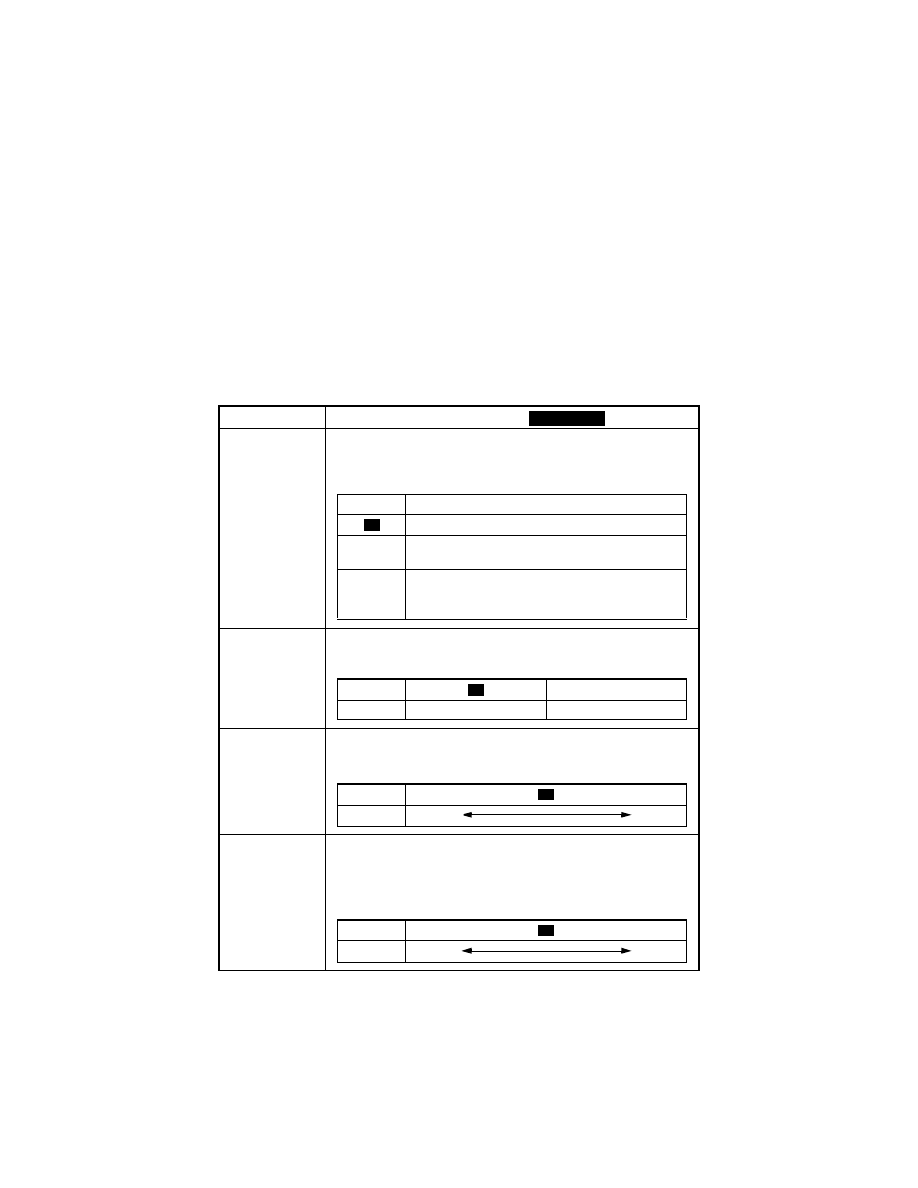
S-16
(3)
Tech.Rep.Choice (Display: - - 2)
• This function allows the Tech. Rep. to make various settings and adjustments.
<Procedure>
1. Enter the code number corresponding to the function to be used from the KEYPAD.
2. Press the START to display the current setting value.
3. Press the CLEAR to clear the current setting value.
4. Enter the new setting value from the KEYPAD.
5. Press the START to validate the new setting value just entered.
If any value outside the available setting range is entered, the Display shows “Err”
rejecting the entry. (The old setting value will reappear on the Display 1 sec. later.)
<Exiting the Mode>
• Press the AUTO RESET until the initial screen reappears.
Code No.
Setting (The default is
).
C-1
<Maintenance Counter Count>
Select the counting method of the maintenance counter.
It is used as guidelines for the number of copies to be made before
the next maintenance time.
C-2
<IU Life Stop>
Select whether to prohibit copying or not when the IU Counter
reaches a life value.
C-3
<ID Adjustment>
Set the central value of image density.
This function is used when image density is not satisfactory.
C-4
<VG Adjustment>
Vary the Vg voltage to adjust image density.
The function is used when a fog or a void occurs.
Increase the setting value to eliminate void.
Decrease the setting value to eliminate fog.
Highlighted
Setting
Description
Not Count
1
Counted (Maintenance Indicator lights when a set-
ting value is reached.)
2
Counted (No new copy cycle can be initiated and
the Tech. Rep. Call LED lights when a setting value
is reached.)
0
Setting
1
Description
Copying allowed
Copying prohibited
0
Setting
0 1 2
4
Description
Lighter
Darker
3
Setting
0 1 3 4
Description
Lighter
Darker
2
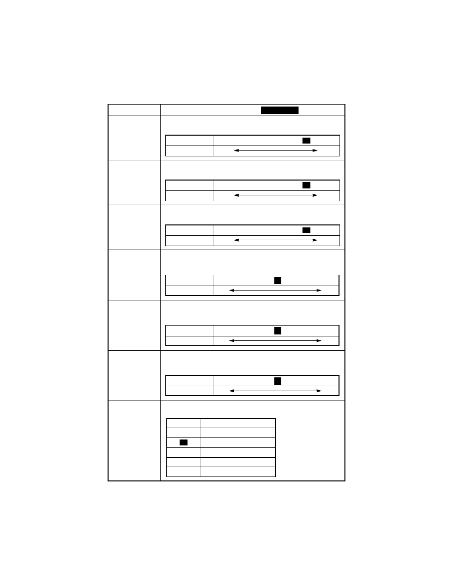
S-17
Code No.
Setting (The default is
).
C-5
<Leading Edge Erase Adjustment>
Select whether to enable or disable the leading edge erase.
C-6
<Trailing Edge Erase Adjustment>
Select whether to enable or disable the trailing edge erase.
C-7
<Top/Bottom Edge Erase Adjustment>
Select the width of erase on the top and bottom edges.
C-8
<Loop Length Adjustment (1st Tray)>
Adjust the length of the loop formed before the Synchronizing Roller
when a skew or misfeed occurs. (1st Tray)
C-9
<Loop Length Adjustment (2nd Tray)>
Adjust the length of the loop formed before the Synchronizing Roller
when a skew or misfeed occurs. (2nd Tray)
C10
<Loop Length Adjustment (Bypass Tray)>
Adjust the length of the loop formed before the Synchronizing Roller
when a skew or misfeed occurs. (Bypass Tray)
C11
<Priority FLS Setting>
Set the size for F4.
Highlighted
Setting
0 1 2 3 5
Description (mm)
0
5
4
Setting
0 1 2 3 5
Description (mm)
0
5
4
Setting
0 1 2 3 5
Description (mm)
0
5
4
Setting
0 .................................
.......................... 14
Description (mm) -3.9
+3.9
7
Setting
0 .................................
.......................... 14
Description (mm) -3.9
+3.9
7
Setting
0 .................................
.......................... 14
Description (mm) -3.9
+3.9
7
Setting
Description
0
330×203
330×210
2
330×216
3
330×220
4
337×206
1
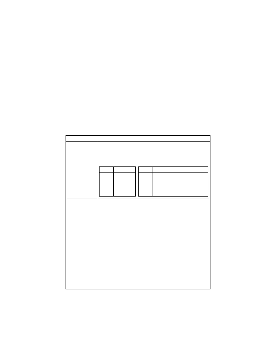
S-18
(4)
Counter Mode (Display: - - 3)
• Shows the number of copies made on each paper size or type.
<Procedure>
1. Enter the code number corresponding to the function to be used from the KEYPAD.
2. Press the START to show the count.
If the count consists of 4 or more digits, it is displayed in two groups alternately as fol-
lows.
E.g.: “123” and “456” alternate if the count is 123,456.
3. Press the PAPER SIZE to select the display of another counter.
4. Call the counter count to be cleared on the Display.
5. Press the CLEAR.
Press INTERRUPT to undo the clearing operation, restoring the original setting.
6. Press the START.
<Exiting the Mode>
• Press the AUTO RESET until the initial screen reappears.
Code No.
Setting
--1
<PM Counter>
Counts the frequency of use of each of the different parts of the
copier.
The count should be cleared when the corresponding PM part is
replaced.
--2
<Maintenance Counter>
Enter a value for the maintenance counter (for any given part).
The count is based on a countdown system and when the set value is
counted down to “0,” the Maintenance Indicator lights.
If counting continues after “0,” a minus sign (-) is appended to the
value shown on the Display.
NOTE
• The above counting method varies depending on the setting made
for “c-1” of Tech. Rep. Choice.
The Display shows “nc1” if copying is prohibited.
<Procedure>
1. Press the START to display the current count.
2. Press the CLEAR to clear the current count.
If the current count is mistakenly cleared, press the INTERRUPT
to restore the count just cleared.
3. Enter the new value from the KEYPAD (that can range from 0 to
999999).
4. Press the START to validate the new setting just made.
Display Description
Display
Description
1
2
3
4
5
Bypass Tray
1st Tray
2nd Tray
3rd Tray
4th Tray
6
7
8
9
10
5th Tray
ADF
IR
Ozone Filter
Image Transfer Roller/Fusing Unit
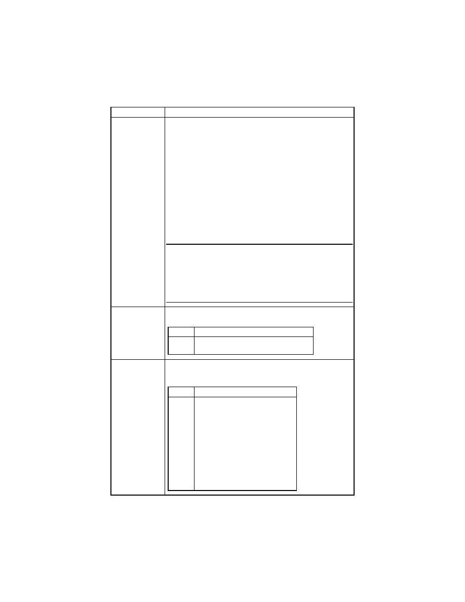
S-19
Code No.
Setting
--3
<IU Life Counter>
Show the count of the IU Life Counter.
The count is based on a countdown system and, if counting continues
after “0,” a minus sign (-) is appended to the value shown on the Dis-
play.
The count is controlled according to the period of time through which
the PC Drum has turned and, when a near-life value is reached, the
Maintenance Indicator blinks.
<Procedure>
1. Press the START to display the current count.
2. Press the CLEAR to clear the current count.
If the current count is mistakenly cleared, press the INTERRUPT
to restore the count just cleared.
3. Press the START to automatically set “40,000.” (The value
“40,000” is the starting value from which it is counted down.)
✽
No value can be set from the KEYPAD.
NOTES
• There are some discrepancies between the count and the actual
number of copies made.
• The setting made in “c-2” of Tech. Rep. Choice determines the
copying operation after the life value has been reached.
If “Copying prohibited” is selected, “nc2” is displayed and the Main-
tenance Indicator lights steadily.
--4
<Application Counter>
The count is made according to the application..
--5
<Jam Counter>
Counts the number of misfeeds that have occurred at different loca-
tions in the copier.
Display
Description
1
2
No. of copies made.
No. of printed pages produced through PC
Display
Description
1
2
3
4
5
6
7
8
9
10
11
12
Bypass Tray
1st Tray
2nd Tray
3rd Tray
4th Tray
5th Tray
Paper take-up and vertical transport
Separator
Fusing Unit
ADF take-up
ADF transport
ADF exit
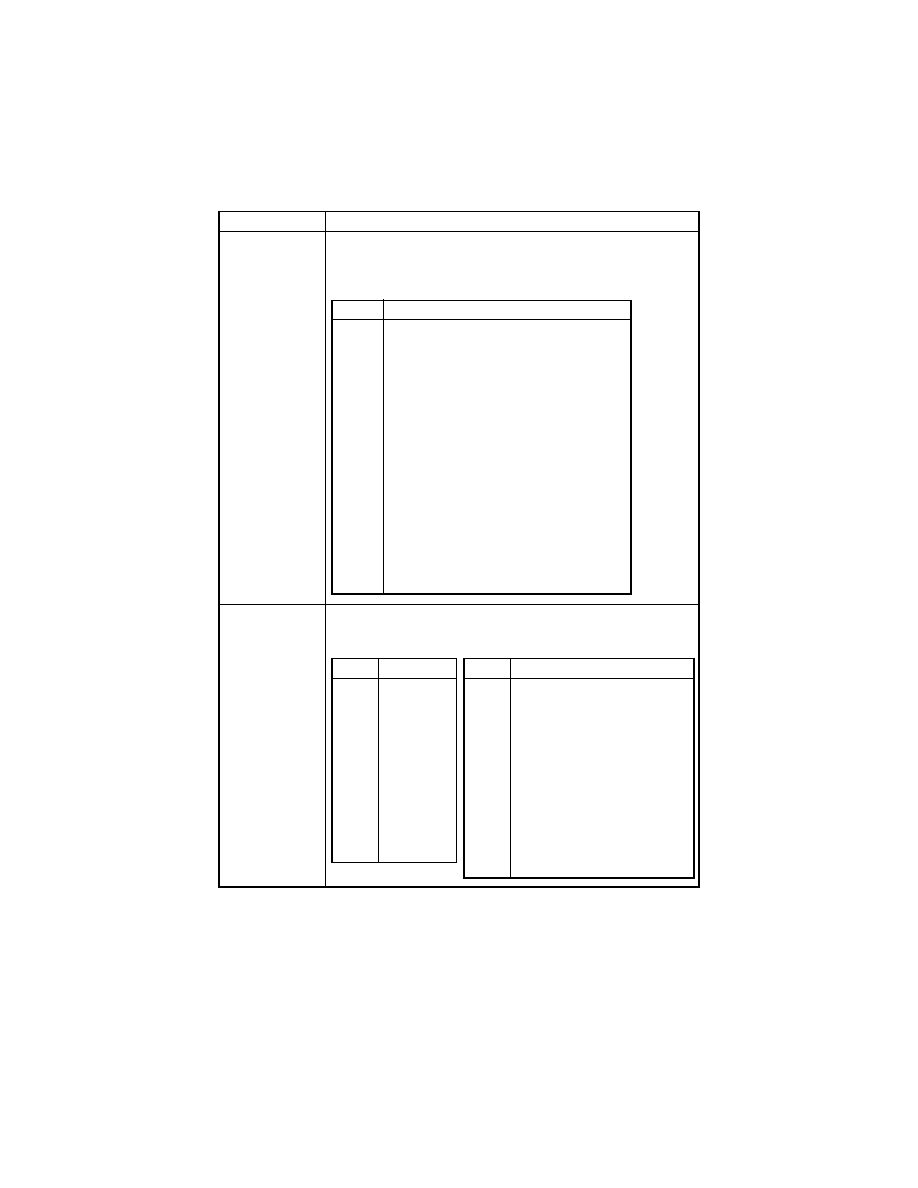
S-20
Code No.
Setting
--6
<Trouble Counter>
Counts the number of malfunctions that have occurred at different
parts of the copier.
If all malfunction counters are “0,” “ALL” and “0” alternate.
--7
<Paper Size Counter>
Counts the number of sheets of paper used according to the size and
type.
Display
Description
1
2
3
4
5
6
7
8
9
10
11
12
13
14
15
16
17
18
Main Motor malfunction
Fusing Cooling Fan Motor malfunction
Power Supply Cooling Fan Motor malfunction
Toner Replenishing Motor malfunction
Faulty image transfer voltage
Warm-up failure
Abnormally low fusing temperature
Abnormally high fusing temperature
Scanner Home Sensor malfunction
Tray Selecting Motor malfunction
Shift Motor malfunction
ATDC Sensor malfunction
ATDC adjustment failure
ASIC/memory malfunction
Polygon Motor malfunction
HSYNC detection failure
EEPROM malfunction
Exposure Lamp malfunction
Display
Description
1
2
3
4
5
6
7
8
9
10
11
12
A3 (R)
B4 (R)
A4 (R)
A4
B5 (R)
B5
A5 (R)
A5
F4 (R)
11×17 (R)
11×14 (R)
8-1/2×14 (R)
Display
Description
13
14
15
16
17
18
19
20
21
22
8-1/2×11 (R)
11×8-1/2
5-1/2×8-1/2 (R)
8-1/2×5-1/2
Other size
Paper enabling Auto Paper/
enabling auto tray switching
Paper disabling Auto Paper/
enabling auto tray switching
Paper disabling Auto Paper/
disabling auto tray switching
OHP
Thick paper

S-21
(5)
ATDC Sensor Output (Display: - - 4)
• This function displays a T/C ratio representing the current ATDC Sensor output value.
• It is used for checking the T/C when image density is not good.
✽
It is not possible to change or reset the sensor output data.
<Exiting the Mode>
• Press the AUTO RESET until the initial screen reappears.
(6)
Level History (Display: - - 5)
• This function displays the grid voltage and developing bias voltage.
✽
It is not possible to change or reset the voltage data.
<Procedure>
1. Press the START to display the current grid voltage (Vg).
2. Press the Zoom “down” key to display the current developing bias voltage (Vb).
Press the Zoom “up” key to return to the display of the current grid voltage (Vg).
<Exiting the Mode>
• Press the AUTO RESET until the initial screen reappears.
(7)
ROM Version (Display: - - 6)
• This function displays the ROM version.
• It is used when upgrading the F/W or the PWB is replaced with a new one.
• The version is displayed in the order of the copier controller and engine.
• The version consists of 12 digits, each being displayed sequentially as the image density
key (darker) (the digits flow in the left direction).
<Procedure>
1. Press the START to display the first 3 digits of the total 12.
2. Press the image density key (darker). Then, the leftmost digit will disappear and,
instead, a new fourth digit will appear.
Press the image density key (darker) a number of times to view the entire digits of the
version.
✽
Pressing the image density key (lighter) will reverse the display of digits.
3. Press the Zoom “down” key to display the version of the engine ROM.
Follow the same steps as those given above.
✽
Pressing the Zoom “up” or “down” key selects the display of the ROM version of the
copier controller or engine.
<Exiting the Mode>
• Press the AUTO RESET until the initial screen reappears.

S-22
(8)
Administrator No. Input (Display: - - 7)
• Set an ID number for opening the “Administrator Mode” screen of Utility Mode from the
KEYPAD.
<Procedure>
1. Press the START to alternately display the current administrator number.
2. Press the CLEAR to clear the current administrator number.
3. Enter the new administrator number from the KEYPAD. The number should consist of 6
digits, ranging from 000000 to 999999.
4. Press the START to validate the new administrator number just entered.
(9)
Change Fixed Zoom (Display: - - 8)
• Change a fixed zoom ratio to a desired value.
✽
The ratios of 50 %, 100 %, and 200 % cannot be changed.
<Procedure>
1. Press the START to display the fixed zoom ratio.
2. Press the RE to select the specific zoom ratio to be changed.
3. Press the CLEAR to clear the zoom ratio selected.
4. Enter the new zoom ratio from the KEYPAD.
5. Press the START to validate the new zoom ratio just entered.
If any value outside the allowable setting range is entered, the Display shows “Err”
rejecting the entry. (The old zoom ratio will reappear on the Display 1 sec. later.)
(10) Marketing Area Setting (Display: - - 9)
• Set the marketing area.
<Procedure>
1. Press the START to display the current marketing area setting.
2. Press the CLEAR to clear the current marketing area setting value.
3. Enter the new setting value from the KEYPAD.
4. Press the START to validate the setting value just entered.
If any value outside the available setting range is entered, the Display shows “Err”
rejecting the entry. (The old setting value will reappear on the Display 1 sec. later.)
Setting
Description
0
JAPAN
1
USA
2
EUROPE
3
China
4
Other areas
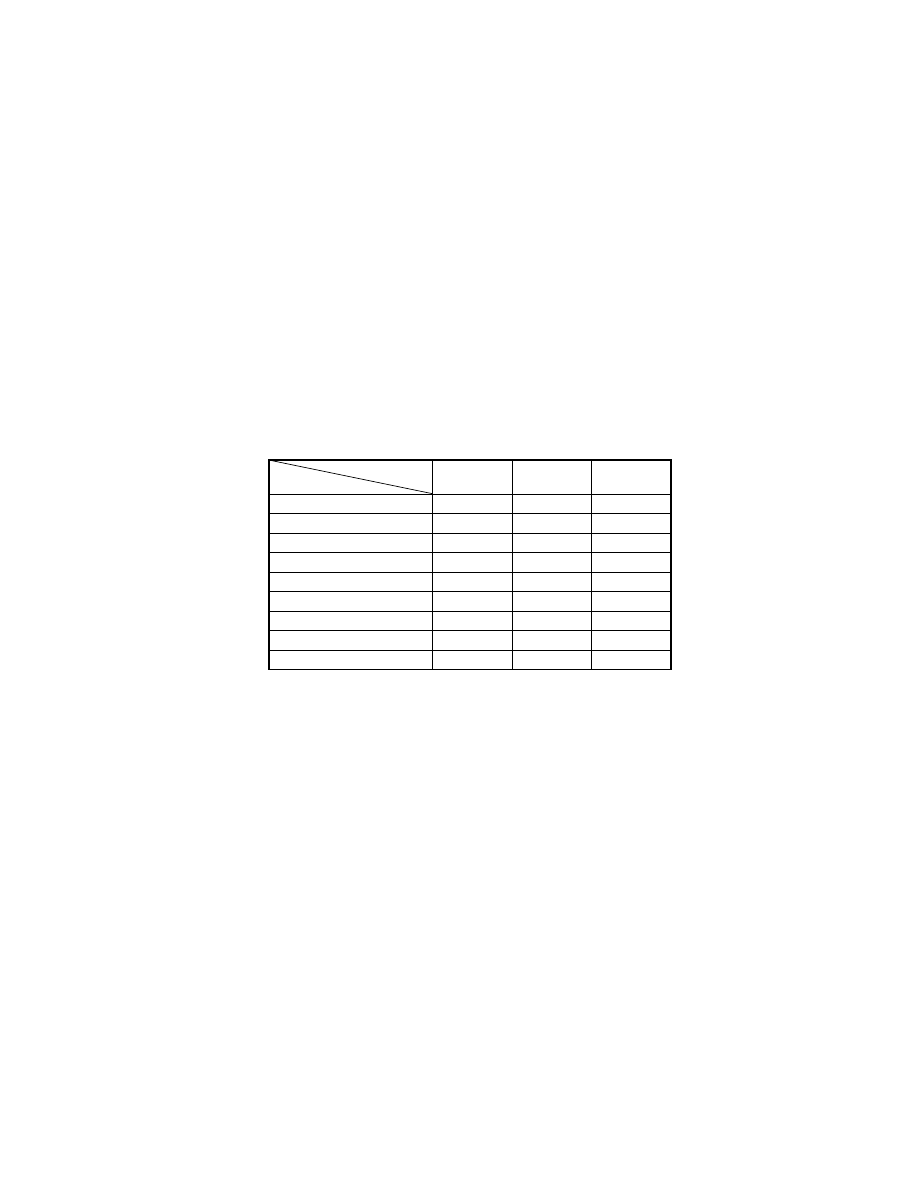
S-23
(11) Memory Clear (Display: - 10)
• This function is used to clear all data except that of the various electronic counters.
<Procedure>
1. Press the START to display “CLr” on the Display.
2. Press the START to blank out the Display.
Then, “CLr” will reappear.
3. Turn OFF and ON the Power Switch.
(12) Total Clear (Display: - 11)
• This function is used to clear all data of the various electronic counters.
<Procedure>
1. Press the START to display “tCL” on the Display.
2. Press the START to blank out the Display.
Then, “tCL” will reappear.
3. Turn OFF and ON the Power Switch.
(13) ADF Document Passage Test (Display: - 12)
• This function is used to check for correct document passage through the ADF when a
document misfeed occurs.
<Procedure>
1. Load a paper stack in the Document Feeding Tray.
2. Press the START to let the ADF start feeding the paper.
3. Press the STOP to stop the sequence.
✽
For details, see the relevant option service manual.
<List of Types of Data to be Cleared>
❍
: Cleared —: Not cleared
*1: Except Copy Track, Input Account, and Total Counter Display by Account.
*2: Except Marketing Area Setting and Serial No. Display.
Door
Open/Close
Memory
Clear
Total
Clear
Jam display
❍
❍
—
Trouble display
—
❍
—
Erratic operation/display
—
❍
—
Utility (*1)
—
❍
—
Tech.Rep.Mode (*2)
—
❍
—
Security
—
❍
—
Adjust
—
❍
—
Job programs
—
❍
—
Electronic counters
—
—
❍
Clearing
Data Cleared

S-24
(14) ADF Original Glass Check (Display: - 13)
• The original scanning area of the ADF is scanned to check for possible dirt or scratches
on the glass. The scanned area is produced as a copy.
<Procedure>
• Press the START to start the sequence.
✽
For details, see the relevant option service manual.
(15) Scanner Move Check (Display: - 14)
• This function is used to check the drive for the Scanner.
• It is also used when securing the Scanner in position with the fixing pin (for transportation
of the machine).
<Procedure>
• Press the START. This will move the Scanner to the left and stop.
(16) Serial No. Display (Display: - 20)
• This function is used to display the serial number (consisting of 8 digits).
<Procedure>
• Press the START to display the serial number.
E.g.: The Display shows “Sn”
→
“12”
→
“345”
→
“678” in that order if the serial number is
12345678.

S-25
4.
SECURITY MODE
• Allows the Tech. Rep. to set the various counters.
4-1.
Settings in the Security Mode
4-2.
Security Mode Setting Procedure
<Procedure>
1. Set the machine into the Tech. Rep. Mode.
2. Press the following keys in this order:
STOP
→
9 (Display: SCU).
3. Enter the code number corresponding to the subfunction to be used.
Code No.: 1 to 4
4. Press the START to display the current setting value.
5. Press the CLEAR to clear the current setting value.
6. Enter the new setting value from the KEYPAD.
7. Press the START to validate the new setting value just entered.
If any value outside the available setting range is entered, the Display shows “Err”
rejecting the entry. (The old setting value will reappear on the Display 1 sec. later.)
<Exiting the Mode>
• Press the AUTO RESET until the initial screen reappears.
Code No.
Description
--1
Total Counter Count Mode
--2
Size Counter Count Mode
--3
Key Counter
--4
Total Counter
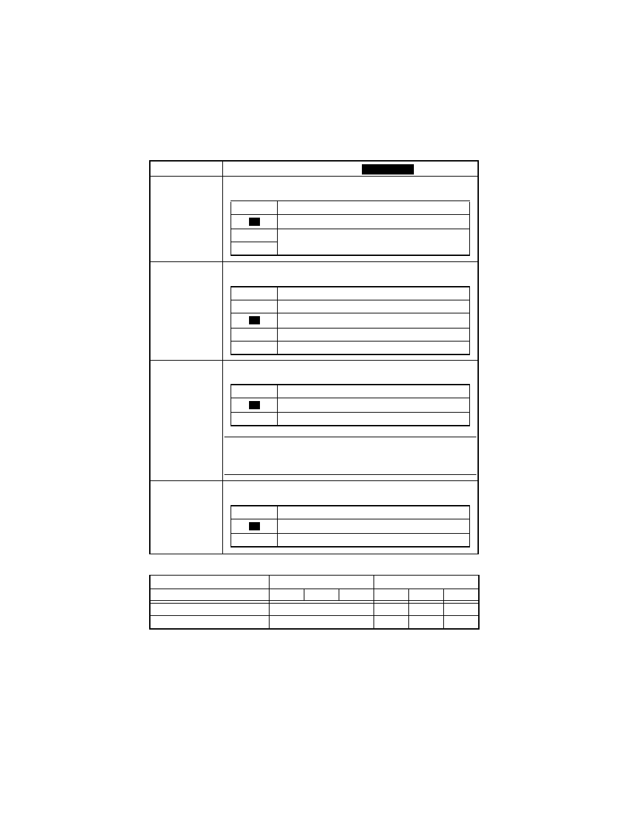
S-26
4-3.
Setting in the Security Mode
<Count-up Table>
1: 1 count 2: 2counts
Code No.
Setting (The default is
).
--1
<Total Counter Count Mode>
Select the condition by which the Counter count is increased.
--2
<Size Counter Count Mode>
Select the size of the paper to be counted by the Size Counter.
--3
<Key Counter>
Set to “1” if a Key Counter is plugged in.
NOTE
• If “0” is set, copies can be made without having to plug the Key
Counter into the socket.
--4
<Total Counter>
Set to “1“ if a Total Counter is plugged in.
Size Counter Count Mode
Size other than those set
Set size
Total Counter Count Mode
0
1
2
0
1
2
Total Counter
1
1
2
2
Size Counter
Not Count
1
1
2
Highlighted
Setting
Description
1 Copy per 1 copy cycle.
1
Multiple count-up according to the paper size and
copying mode.
2
0
Setting
Description
0
Not Count
A3/Ledger
2
A3/B4/8-1/2×14/11×17
3
A3/B4/8-1/2×14/11×17/11×14/F4
1
Setting
Description
Plug-In Counter not plugged in
1
Plug-In Counter plugged in
0
Setting
Description
Mechanical Total Counter not installed
1
Mechanical Total Counter installed
0

S-27
5.
ADJUST MODE
• Used at the factory for making adjustments.
5-1.
Settings in the Adjust Mode
5-2.
Adjust Mode Setting Procedure
<Procedure>
1. Set the machine into the Tech. Rep. Mode.
2. Press the following keys in this order:
STOP
→
START.
3. Enter the code number corresponding to the subfunction to be used.
Code No.: 1 to 12 and 20
4. Press the START to display the current setting value.
5. Press the CLEAR to clear the current setting value.
6. Enter the new setting value from the KEYPAD.
If any value outside the available setting range is entered, the Display shows “Err”
rejecting the entry. (The old setting value will reappear on the Display 1 sec. later.)
7. Press the START to validate the new setting value just entered.
<Exiting the Mode>
• Press the AUTO RESET until the initial screen reappears.
Code No.
Description
--1
Printer CD Registration adjustment
--2
Printer FD Registration adjustment
--3
Scanner CD Zoom adjustment
--4
Scanner FD Zoom adjustment
--5
Scanner CD Registration adjustment
--6
Scanner FD Registration adjustment
--7
ADF FD Zoom adjustment
--8
ADF CD Registration adjustment
--9
ADF FD Registration adjustment
-10
ATDC Sensor Gain Manual adjustment
-11
-12
Test Print
-20
This test is for factory adjustment only and should
NOT be used.
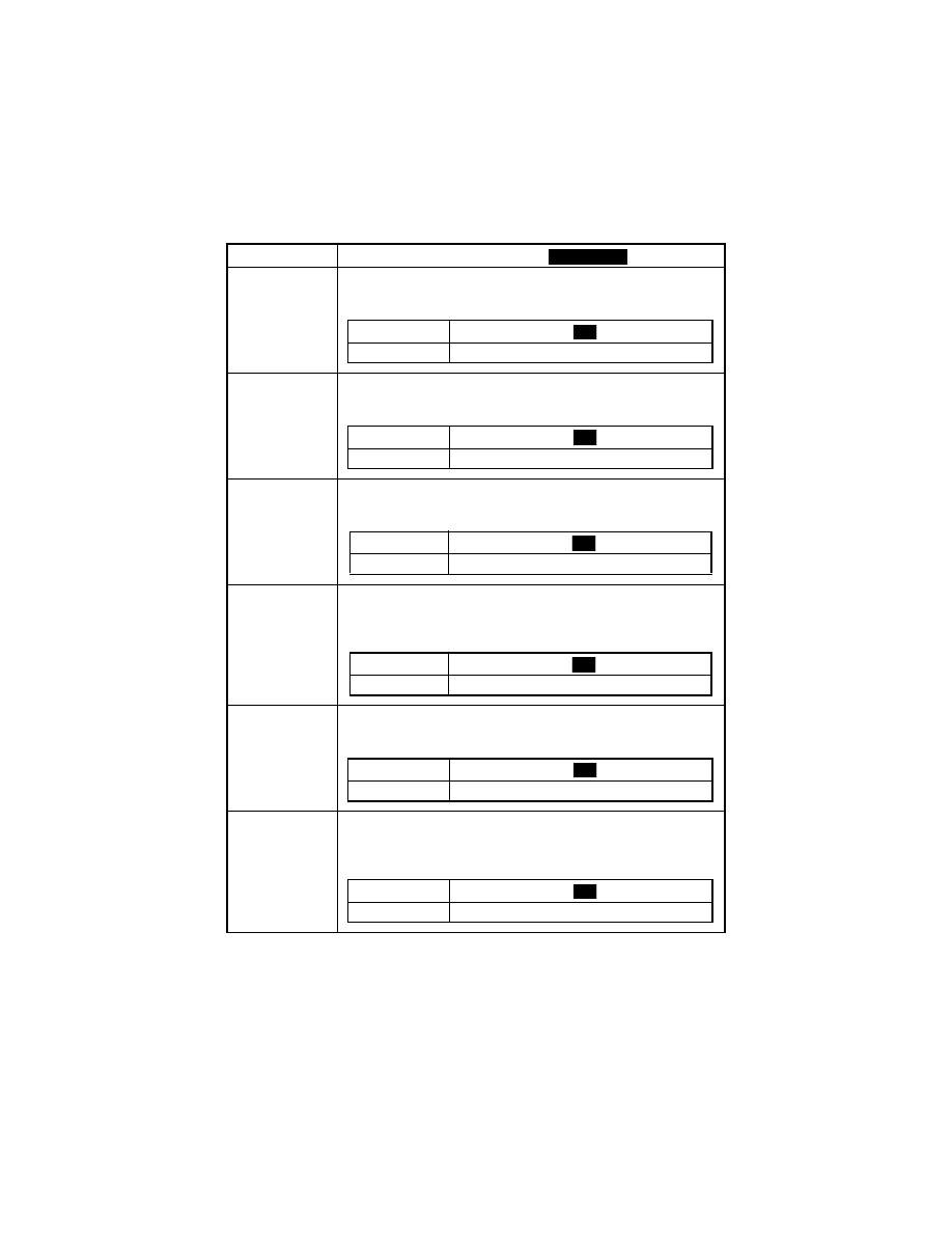
S-28
5-3.
Setting in the Adjust Mode
Code No.
Setting (The default is
).
--1
<Printer CD Registration adjustment>
Adjust registration in the CD direction on the printer (engine) side.
It is used when the PH Unit has been replaced.
--2
<Printer FD Registration adjustment>
Adjust registration in the FD direction on the printer (engine) side.
It is used when the PH Unit has been replaced.
--3
<Scanner CD Zoom adjustment>
Adjust the zoom ratio in the CD direction on the Scanner (IR) side.
It is used when the PH Unit or CCD Unit has been replaced.
--4
<Scanner FD Zoom adjustment>
Adjust the zoom ratio in the FD direction on the Scanner (IR) side.
It is used when the PH Unit or the Scanner Drive Cables have been
replaced, or when the Scanner has been removed.
--5
<Scanner CD Registration adjustment>
Adjust registration in the CD direction on the Scanner (IR) side.
It is used when the PH Unit or CCD Unit has been replaced.
--6
<Scanner FD Registration adjustment>
Adjust registration in the FD direction on the Scanner (IR) side.
It is used when the PH Unit or the Scanner Drive Cables have been
replaced, or when the Scanner has been removed.
Highlighted
Setting
60 ..............................
........................ 140
Description (mm) -4 ................................. 0 ............................ +4
100
Setting
67 ..............................
........................ 133
Description (mm) -6.14 ............................ 0 ....................... +6.14
100
Setting
97..............................
........................ 103
Description (%) -1.2 ..............................0 ......................... +1.2
100
Setting
97..............................
........................ 103
Description (%) -1.2 ..............................0 ......................... +1.2
100
Setting
20 ..............................
........................ 180
Description (mm) -8 ................................. 0 ............................ +8
100
Setting
60 ..............................
........................ 140
Description (mm) -4 ................................. 0 ............................ +4
100
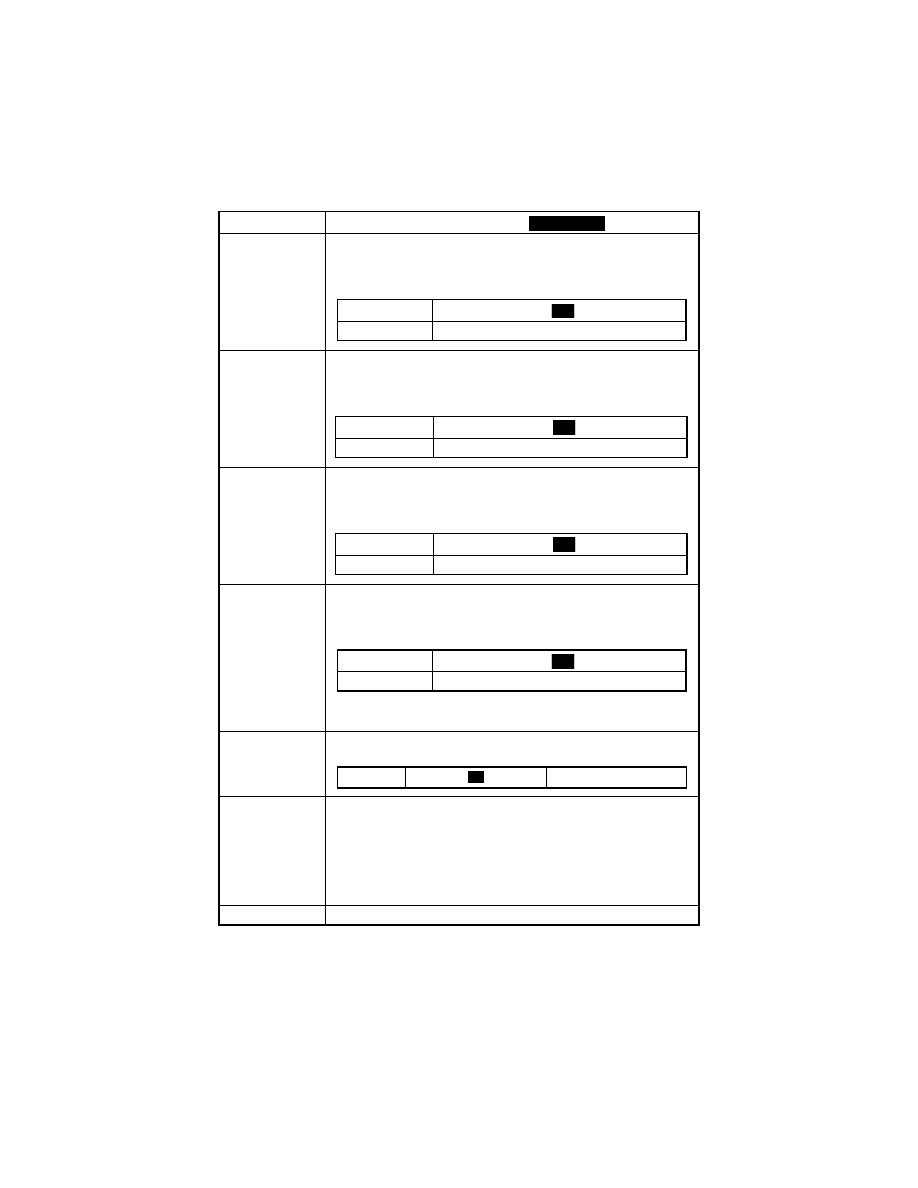
S-29
Code No.
Setting (The default is
).
--7
<ADF FD Zoom adjustment>
Adjust the zoom ratio in the FD direction on the ADF side.
It is used when the machine is set up, the PH Unit or Scanner Drive
Cables have been replaced, or the Scanner has been removed.
--8
<ADF CD Registration adjustment>
Adjust registration in the CD direction on the ADF side.
It is used when the machine is set up, or the PH Unit or CCD Unit has
been replaced.
--9
<ADF FD Registration adjustment>
Adjust registration in the FD direction on the ADF side.
It is used when the PH Unit or Scanner Drive Cables have been
replaced, or the Scanner has been removed.
-10
<ATDC Sensor Gain Manual adjustment>
Adjust the ATDC Sensor voltage.
It is used when an IU of another machine is to be used or the T/C con-
trol voltage is to be changed.
✽
The value, to which F-8 (ATDC Sensor Automatic Adjustment) has
been adjusted, is to be the setting value.
-11
Be sure to set to “1” whenever Memory Clear has been effected on
the 18-cpm machine.
-12
<Test Print>
This function is used to produce a test print, when a check is made
after a setting value of an Adjust function has been changed and on
image.
<Procedure>
1. Select the paper source (Bypass Tray cannot be selected).
2. Press the START to let the machine produce a test print.
-20
✽
This test is for factory adjustment only and should NOT be used.
Highlighted
Setting
87..............................
........................ 113
Description (%) 9.48............................100 ..................... 105.2
100
Setting
20 ..............................
........................ 180
Description (mm) -8.0 .............................. 0 ......................... +8.0
100
Setting
50 ..............................
........................ 150
Description (mm) -5 ................................. 0 ............................ +5
100
Setting
123............................
........................ 186
Description (V) 5.39........................... 6.79 ....................... 8.15
155
Setting
1
0

S-30

TROUBLESHOOTING


T-1
1.
INTRODUCTION
1-1.
Reading the Text
1. The paper transport failure troubleshooting procedures are given according to the
symptom. First identify the location where the paper is present and start the procedure
for that particular location. For malfunction troubleshooting, start with step 1 and
onward.
2. Make checks in the numerical order of steps and, if an item is checked okay, go to the
next step.
<E.g.: Pattern 1>
<E.g.: Pattern 2>
Step
Check
Result
Action
1
—
NO
—
2
Step
Check
Result
Action
1
—
YES
—
NO
—
2
Go to the next step if you answered
YES.
Go to the next step if it checks okay.
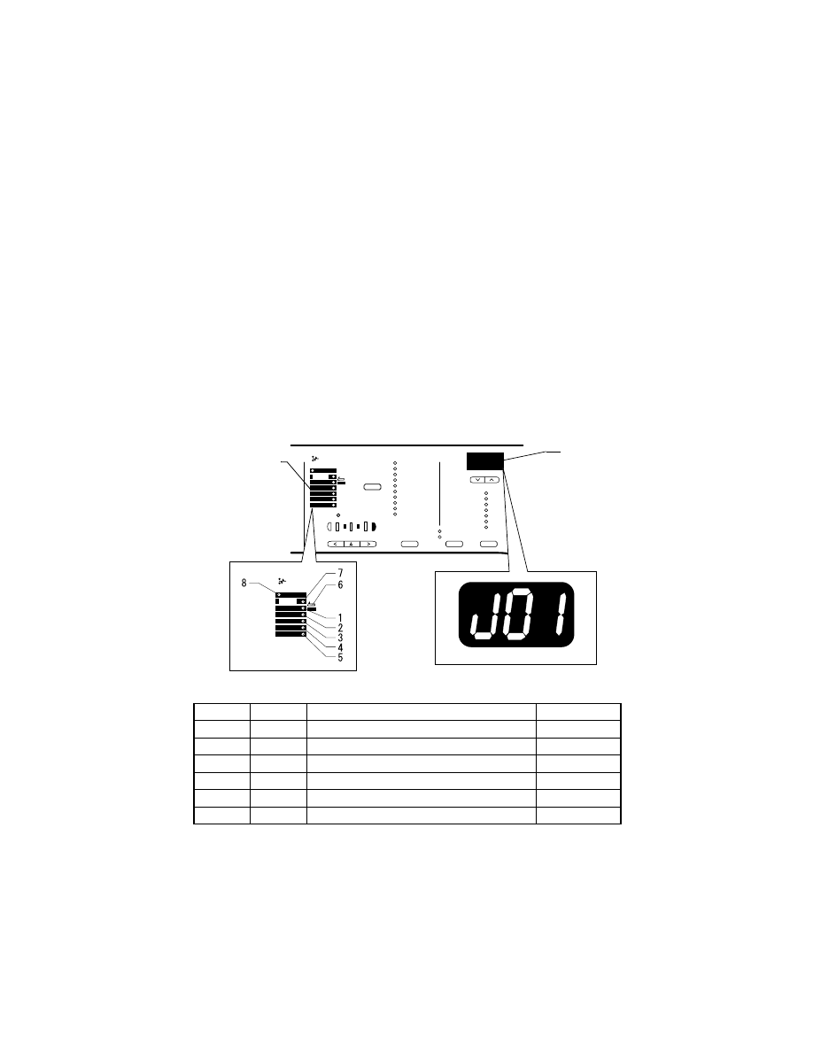
T-2
2.
PAPER TRANSPORT FAILURE
2-1.
Paper Misfeed Detection
(1)
Outline
• A paper misfeed is detected by detecting different states of signals (H, L) of several sen-
sors located near the paper take-up section and the Exit Paper Sensor.
• The timings of the rising and falling edges of the paper take-up-related sensors and the
Exit Paper Sensor are monitored to detect a misfeed of paper being fed through the
copier.
• The states (H, L) of the paper take-up-related sensors and the Exit Paper Sensor are
monitored to detect a sheet of paper left in the copier.
• All drives are brought to an immediate stop when a sheet of paper misfeed or left in the
copier is detected.
2-2.
Paper Misfeed
When a paper misfeed occurs, the control panel shows the misfeed location and paper
location.
LED No.
Code
Misfeed/Paper Location
Action Ref. Page
1
J01
Misfeed at the 1st Tray
☞
T-7
2
J02
Misfeed at the 2nd Tray
☞
T-11
3
J03
Misfeed at the 3rd Tray
☞
T-11
4
J04
Misfeed at the 4th Tray
☞
T-11
5
J05
Misfeed at the 5th Tray
☞
T-11
6
J06
Misfeed at the Bypass Tray
☞
T-7
4022T502AA
4022T503AA
4022T501AA
Misfeed Location
Indicator LED
Display
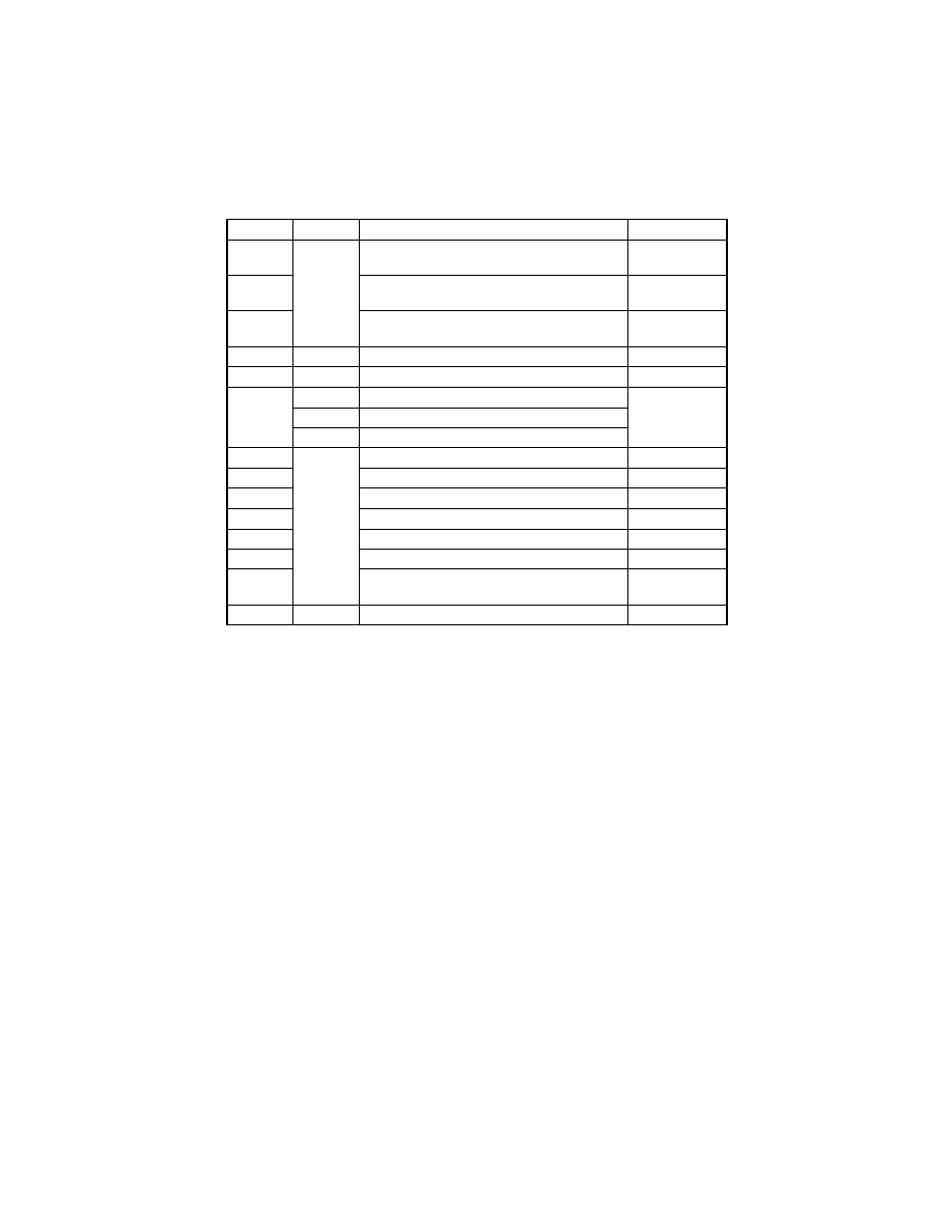
T-3
LED No.
Code
Misfeed/Paper Location
Action Ref. Page
2/3
J1
Misfeed on paper transport path between PC1
and PC12 (3rd Tray)
☞
T-11
3/4
Misfeed on paper transport path between PC12
(3rd Tray) and PC12 (4th Tray)
☞
T-11
4/5
Misfeed on paper transport path between PC12
(4th Tray) and PC12 (5th Tray)
☞
T-11
7
J2
Misfeed at the PC Drum
☞
T-13
7
J3
Misfeed at the Fusing Unit
☞
T-16
8
J80
Original misfeed: ADF Separator
See option
service manual.
J81
Original misfeed: ADF registration
J83
Original misfeed: ADF exit
1/7
J – –
Paper left: PC1
☞
T-7
7
Paper left: PC3
☞
T-16
2
Paper left: 2nd Tray Paper Take-Up Sensor
☞
T-11
3
Paper left: 3rd Tray Paper Take-Up Sensor
☞
T-11
4
Paper left: 4th Tray Paper Take-Up Sensor
☞
T-11
5
Paper left: 5th Tray Paper Take-Up Sensor
☞
T-11
8
Paper left: ADF
See option
service manual.
6
byp
Paper left: Manual Bypass Tray
☞
T-7
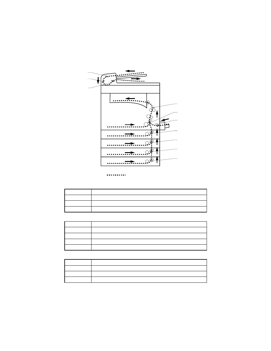
T-4
2-3.
Misfeed Detection Sensor Layout
Copier
Paper Feed Cabinet (option)
ADF (option)
Symbol
Name
PC1
Synchronizing Roller Sensor
PC2
Manual Feed Paper Sensor
PC3
Exit Paper Sensor
Symbol
Name
PC12*
2nd Tray Paper Take-Up Sensor
PC12*
3rd Tray Paper Take-Up Sensor
PC12*
4th Tray Paper Take-Up Sensor
PC12*
5th Tray Paper Take-Up Sensor
Symbol
Name
PC3*
Registration Sensor
PC4*
Separator Sensor
PC5*
Paper Exit Sensor
PC4*
PC3*
PC5*
PC3
PC1
PC2
PC12*
PC12*
PC12*
PC12*
Paper Path
4022T504AA

T-5
<Resetting the Misfeed Display>
Misfeed Location
Resetting Procedure
Misfeed in
the copier
Misfeed at 1st Tray J01,
misfeed at Multiple Bypass Tray J06,
misfeed at Manual Bypass Tray J06,
misfeed at PC Drum J2,
misfeed at Fusing Unit J3,
paper left J - -
Open the Right Door or slide out
the 1st Tray, remove all sheets of
paper misfeed and left inside, and
close the Right Door.
Paper wedged at Manual Bypass Tray byp Pull the paper wedged out of the
tray. (Removing the paper will
reset the misfeed display.)
Misfeed in the option:
J02, J03, J04, J05, J1, J80, J81, and J83
Remove all sheets of paper mis-
feed and left inside and then raise
and lower or disconnect and
reconnect the option.

T-6
2-4.
Types of Misfeed Detection and Detection Timings
• The following list the types of misfeed detection and detection timings for different mis-
feed locations.
• The symbol “L” (for the leading edge) and “T” (for the trailing edge) given in ( ) indicate
the particular edge of the paper detected by the sensor.
NOTE
• For the types of misfeed detection and detection timings of options, see the relevant
option service manual.
<Misfeed at the Paper Take-Up Section>
<Misfeed at the PC Drum>
<Misfeed at the Fusing Unit>
Type
Detection Start
Paper Detection
Misfeed at 1st Tray
J01
Paper Take-Up Solenoid (SL1)
energized
Synchronizing Roller Sensor
(PC1) (L)
Misfeed at Manual
Bypass Tray J06
Manual Bypass Solenoid (SL2)
energized
Synchronizing Roller Sensor
(PC1) (L)
Misfeed at Multiple
Bypass Tray J06
Multiple Bypass Solenoid (SL21)
energized
Synchronizing Roller Sensor
(PC1) (L)
Type
Detection Start
Paper Detection
Misfeed at PC Drum
J2
Synchronizing Roller Sensor (PC1)
(L)
Exit Paper Sensor (PC3) (L)
Synchronizing Roller Sensor (PC1)
(L)
Synchronizing Roller Sensor
(PC1) (T)
Type
Detection Start
Paper Detection
Misfeed at Fusing
Unit J3
Synchronizing Roller Sensor (PC1)
(T)
Exit Paper Sensor (PC3) (T)
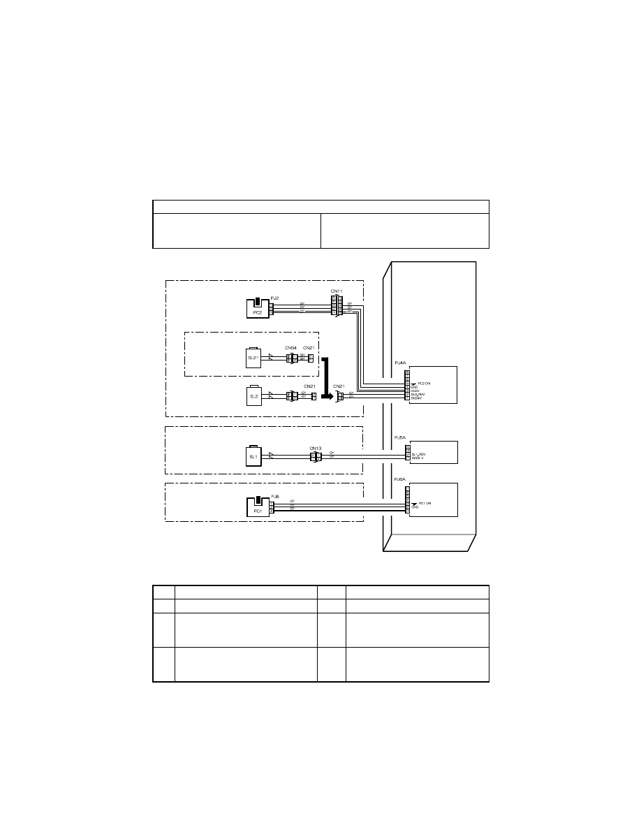
T-7
3.
MISFEED TROUBLESHOOTING PROCEDURES
3-1.
Misfeed at Copier Paper Take-Up J01 and Misfeed at Bypass
Tray J06
Misfeed at 1st Tray J01 Troubleshooting Procedures
Relevant Electrical Parts
Synchronizing Roller Sensor (PC1)
Manual Feed Paper Sensor (PC2)
Paper Take-Up Solenoid (SL1)
Manual Bypass Solenoid (SL2)
Multiple Bypass Solenoid (SL21)
Master Board (PWB-A)
Step
Check
Result
Action
1
Paper meets product specifications.
NO
• Change paper.
2
Paper is curled, wavy, or damp.
YES
• Change paper.
• Instruct user to load paper that
meets product specifications.
3
Edge Guide and Trailing Edge Stop
are at correct position to accommo-
date paper.
NO
• Adjust as necessary.
CN26
PC1 ANODE
Multiple Bypass
MANUAL BYPASS SECTION
DRAWER SECTION
TRANSPORT SECTION
Multiple
Bypass Solenoid
Manual Feed
Bypass Solenoid
Paper Take-Up
Solenoid
Synchronizing
Roller Senser
Manual Feed
Paper Senser
PWB-A
Master Board
4022T522AA
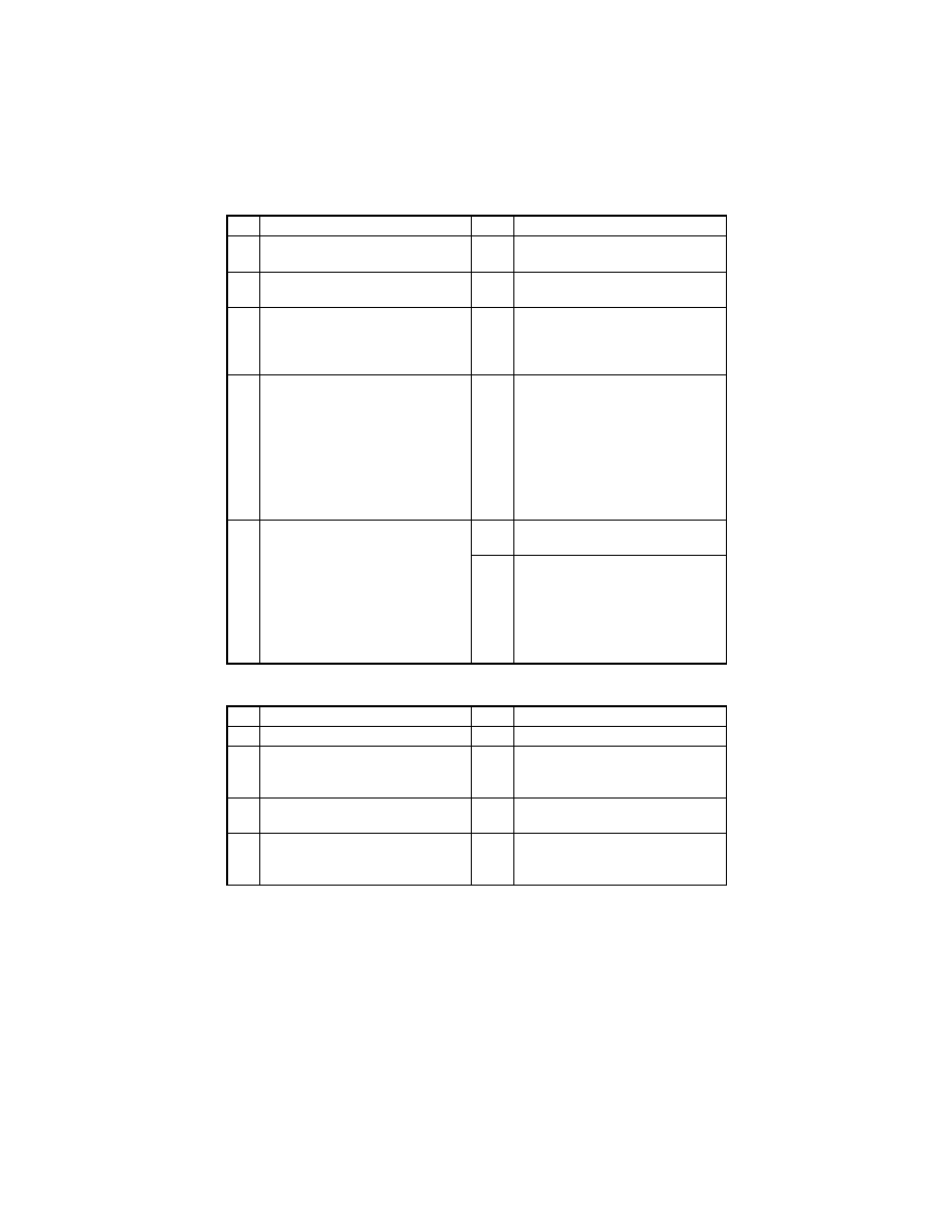
T-8
Misfeed at Manual Bypass Tray J06 Troubleshooting Procedures
Step
Check
Result
Action
4
Paper Take-Up Roll (1st Tray) is dirty,
scratchy, deformed, or worn.
YES
• Clean or change.
5
Paper Separator Roll (1st Tray) is
dirty, scratchy, deformed, or worn.
YES
• Clean or change.
6
Paper Take-Up Roll drive shaft turns
when the Start key is pressed.
NO
• Reinstall the Paper Take-Up Roll
drive shaft.
• Reinstall the Paper Take-Up Roll
drive gear and spring.
7
Paper Take-Up Solenoid (SL1) is
operational when the Start key is
pressed.
<Check Procedure>
Check voltage across a Master Board
(copier: PWB-A) pin and GND.
• Voltage across PJ5A-2 and GND
In standby: DC24 V
When pressed: DC0 V
NO
• Change Paper Take-Up Solenoid
(SL1).
8
Synchronizing Roller Sensor (PC1) is
operational.
<Check Procedure>
Check voltage across a Master Board
(copier: PWB-A) pin and GND when
the sensor is blocked.
• Voltage across PJ6A-3 and GND
When blocked: DC5 V
When unblocked: DC0 V
NO
• Change Synchronizing Roller Sen-
sor (PC1).
YES
• Change Master Board (copier:
PWB-A).
Step
Check
Result
Action
1
Paper meets product specifications.
NO
• Change paper.
2
Paper is curled, wavy, or damp.
YES
• Change paper.
• Instruct user to load paper that
meets product specifications.
3
Paper Guides are at correct position
to accommodate paper.
NO
• Adjust as necessary.
4
Transport Roller (Manual Bypass
Tray) is dirty, scratchy, deformed, or
worn.
YES
• Clean or change.
T-9
Misfeed at Multiple Bypass Tray J06 Troubleshooting Procedures
Step
Check
Result
Action
5
Manual Bypass Solenoid (SL2) is
operational when the Start key is
pressed.
<Check Procedure>
Check voltage across a Master Board
(copier: PWB-A) pin and GND.
• Voltage across PJ4A-2 and GND
In standby: DC24 V
When pressed: DC0 V
NO
• Change Manual Bypass Solenoid
(SL2).
6
Manual Feed Paper Sensor (PC2) is
operational.
<Check Procedure>
Check voltage across a Master Board
(copier: PWB-A) pin and GND when
the sensor is blocked.
• Voltage across PJ4A-5 and GND
When unblocked: DC5 V
When blocked: DC0 V
NO
• Change Manual Feed Paper Sen-
sor (PC2).
7
Synchronizing Roller Sensor (PC1) is
operational.
<Check Procedure>
Check voltage across a Master Board
(copier: PWB-A) pin and GND when
the sensor is blocked.
• Voltage across PJ6A-3 and GND
When blocked: DC5 V
When unblocked: DC0 V
NO
• Change Synchronizing Roller Sen-
sor (PC1).
YES
• Change Master Board (copier:
PWB-A).
Step
Check
Result
Action
1
Paper meets product specifications.
NO
• Change paper.
2
Paper is curled, wavy, or damp.
YES
• Change paper.
• Instruct user to load paper that
meets product specifications.
3
Paper Guides are at correct position
to accommodate paper.
NO
• Adjust as necessary.
4
• Paper Take-Up Roll drive shaft
(Multiple Bypass Tray) turns when
the Start key is pressed.
NO
• Reinstall.

T-10
Step
Check
Result
Action
5
Multiple Bypass Solenoid (SL21) is
operational when the Start key is
pressed.
<Check Procedure>
Check voltage across a Master Board
(copier: PWB-A) pin and GND.
• Voltage across PJ4A-2 and GND
In standby: DC24 V
When pressed: DC0 V
NO
• Change Multiple Bypass Solenoid
(SL21).
6
Paper Take-Up Roll (Multiple Bypass
Tray) is dirty, scratchy, deformed, or
worn.
YES
• Clean or change.
7
Separator Roll (Multiple Bypass Tray)
is dirty, scratchy, deformed, or worn.
YES
• Clean or change.
8
Synchronizing Roller Sensor (PC1) is
operational.
<Check Procedure>
Check voltage across a Master Board
(copier: PWB-A) pin and GND when
the sensor is blocked.
• Voltage across PJ6A-3 and GND
When unblocked: DC5 V
When blocked: DC0 V
NO
• Change Synchronizing Roller Sen-
sor (PC1).
YES
• Change Master Board (copier:
PWB-A).
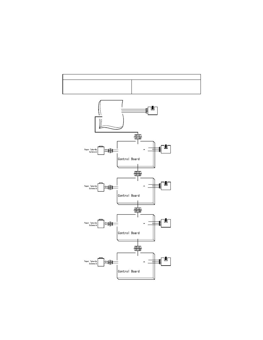
T-11
3-2.
Misfeed at Paper Feed Cabinet Paper Take-Up and Transport
Section J02, J03, J04, J05, J1 (PF-121)
Relevant Electrical Parts
Paper Take-Up Solenoid (SL11)
Synchronizing Roller Sensor (PC1)
Paper Take-Up Sensor (PC12)
Master Board (PWB-A)
Control Board (PWB-A): PF-121
SL11
CN53
PJ3A-2A(GND)
PJ3A-1A(SL11 ON)
PJ3A-3B(DC5 V)
PJ3A-1B(GND)
CN25
PJ6
PC1
PJ6A-3(PC1 ON)
PJ6A-2(GND)
PJ6A-1(PC1 ANODE)
PWB-A
Master Board
PJ18A
PJ1A
PWB-A
2nd Tray
3rd Tray
4th Tray
(PF-121)
Synchronizing
Roller Sensor
13
13
13
SL11
CN53
PJ3A-2A(GND)
PJ3A-1A(SL11 ON)
PJ1A
PJ2APJ1A
SL11
CN53
PJ3A-2A(GND)
PJ3A-1A(SL11 ON)
PJ1A
PJ2APJ1A
PJ2APJ1A
PJ3A-2B( PC12ON)
PJ53
PC12
Paper
Take-Up
Sensor
PJ3A-3B(DC5 V)
PJ3A-1B(GND)
PWB-A
(PF-121)
PJ3A-2B( PC12ON)
PJ53
PC12
Paper
Take-Up
Sensor
PJ3A-3B(DC5 V)
PJ3A-1B(GND)
PWB-A
(PF-121)
PJ3A-2B( PC12ON)
PJ53
PC12
Paper
Take-Up
Sensor
5th Tray
13
SL11
CN53
PJ3A-2A(GND)
PJ3A-1A(SL11 ON)
PJ1A
PJ3A-3B(DC5 V)
PJ3A-1B(GND)
PWB-A
(PF-121)
PJ3A-2B( PC12ON)
PJ53
PC12
Paper
Take-Up
Sensor
4022T543AA
T-12
Misfeed at Paper Feed Cabinet Paper Take-Up and Transport Section J02, J03, J04, J05,
J1 (PF-121) Troubleshooting Procedures
• Paper is not taken up at all.
• Paper is at a stop near the vertical transport section or Synchronizing Roller.
Step
Check
Result
Action
1
Paper meets product specifications.
NO
• Change paper.
2
Paper is curled, wavy, or damp.
YES
• Change paper.
• Instruct user to load paper that
meets product specifications.
3
Edge Guides and Trailing Edge Stop
are at correct position to accommo-
date paper.
NO
• Adjust position as necessary.
4
Paper Take-Up Roll is dirty, scratchy,
deformed, or worn.
YES
• Clean or change.
5
Mylar is dirty, scratchy, or deformed.
YES
• Clean or change.
6
Separator Fingers are dirty or
deformed.
YES
• Clean or change.
7
Paper guide plate is dirty or
deformed.
YES
• Clean or change.
8
Paper Take-Up Solenoid (SL11)
operation check:
The voltage across PJ3A-1A on Con-
trol Board (PF-121: PWB-A) and
GND changes from DC0 V to DC24 V
when the Start key is pressed.
YES
• Change Paper Take-Up Solenoid
(SL11).
NO
• Change Control Board (PF-121:
PWB-A).
9
Paper Take-Up Sensor (PC12) oper-
ation check:
The voltage across PJ3A-2 on Con-
trol Board (PF-121: PWB-A) and
GND is DC 5 V when the sensor is
unblocked and DC 0 V when the sen-
sor is blocked.
YES
• Change Control Board (PF-121:
PWB-A) and/or Master Board
(copier: PWB-A).
NO
• Correct actuator and/or change
Paper Take-Up Sensor (PC12).
Step
Check
Result
Action
1
Vertical Transport Roller/Rolls are
dirty, deformed, or worn.
YES
• Clean or change.
2
Paper is curled, wavy, or damp.
YES
• Change paper.
• Instruct user to load paper that
meets product specifications.
3
Synchronizing Roller Sensor (PC1)
operation check:
The voltage across PJ6A-3 on Mas-
ter Board (copier: PWB-A) and GND
is DC5 V when the sensor is blocked
and DC0 V when the sensor is
unblocked.
YES
• Change Master Board (copier:
PWB-A).
NO
• Correct actuator and/or change
Synchronizing Roller Sensor
(PC1).
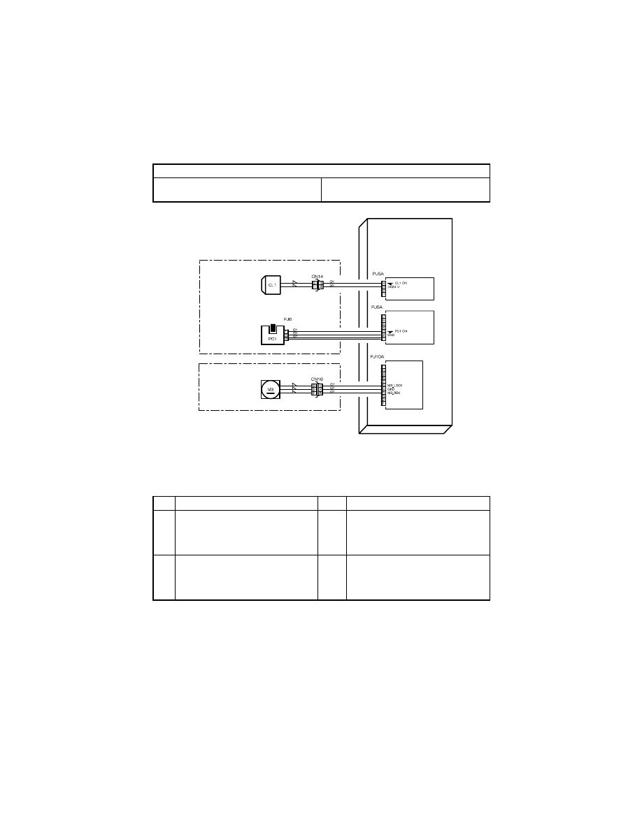
T-13
3-3.
Misfeed at PC Drum J2
Misfeed at PC Drum J2 Troubleshooting Procedures
• Paper is at a stop at the Synchronizing Roller.
Relevant Electrical Parts
Synchronizing Roller Sensor (PC1)
Fusing Cooling Fan Motor (M3)
Synchronizing Roller Clutch (CL1)
Master Board (PWB-A)
Step
Check
Result
Action
1
Synchronizing Rollers are dirty,
scratchy, deformed, or worn.
YES
• Clean or change the Synchronizing
Rollers.
• Clean or change the Paper Dust
Remover.
2
Loop length is set to an appropriate
value.
NO
• Adjust loop length using Tech. Rep.
Choice.
• For details, see DIS/REASSEM-
BLY, ADJUSTMENT.
PC1 ANODE
PWB-A
Master Board
TRANSPORT SECTION
FUSING SECTION
Synchronizing
Roller Senser
Fusing Cooling
Fan Motor
Synchronizing
Roller Clutch
4022T523AA
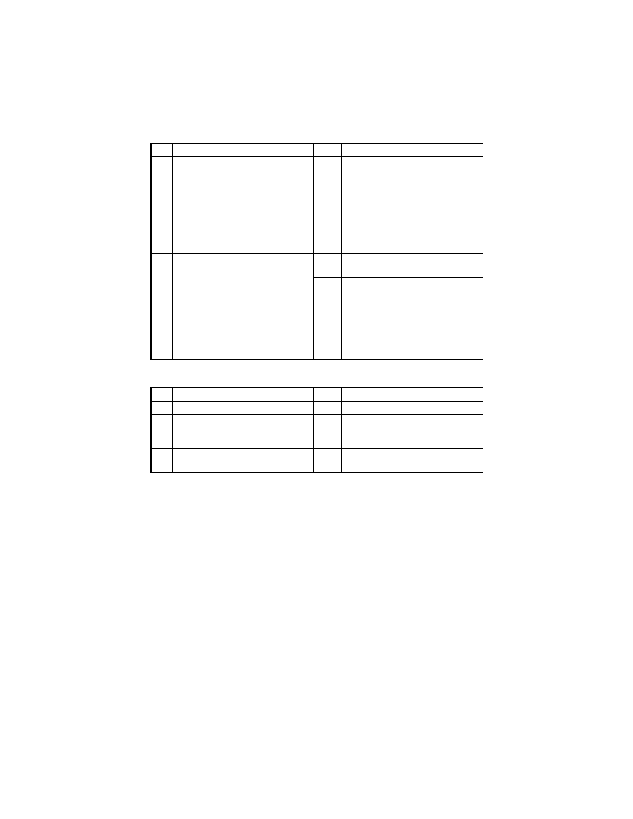
T-14
• Paper is at a stop at the PC Drum.
Step
Check
Result
Action
3
Synchronizing Roller Sensor (PC1) is
operational.
<Check Procedure>
Check voltage across a Master Board
(copier: PWB-A) pin and GND when
the sensor is blocked.
• Voltage across PJ6A-3 and GND
When blocked: DC5 V
When unblocked: DC0 V
NO
• Change Synchronizing Roller Sen-
sor (PC1).
4
The following voltage is supplied to
the Synchronizing Roller Clutch
(CL1).
<Check Procedure>
Check voltage across a Master Board
(copier: PWB-A) pin and GND when
the Start key is pressed.
• Voltage across PJ5A-4 and GND
In standby: DC24 V
When pressed: DC0 V
YES
• Change Synchronizing Roller
Clutch (CL1).
NO
• Change Master Board (copier:
PWB-A).
Step
Check
Result
Action
1
Image Transfer Roller is dirty.
YES
• Clean or change.
2
PC Drum Paper Separator Fingers
are dirty, scratchy, deformed, worn, or
damaged.
YES
• Clean or change.
3
Charge Neutralizing Plate is dirty,
scratched, broken, or bent.
YES
• Clean, correct, or change.

T-15
• Paper is at a stop at the transport section.
Step
Check
Result
Action
1
Transport guide plate is dirty,
scratchy, deformed, worn, or dam-
aged.
YES
• Clean or change.
2
The following voltage is supplied to
the Fusing Cooling Fan Motor (M3).
<Check Procedure>
Check voltage across a Master Board
(copier: PWB-A) pin and GND when
the Start key is pressed.
• Voltage across PJ10A-4 and GND
During decelerated rotation: DC8 V
During full speed rotation: DC24 V
YES
• Change Fusing Cooling Fan Motor
(M3).
NO
• Change Master Board (copier:
PWB-A).
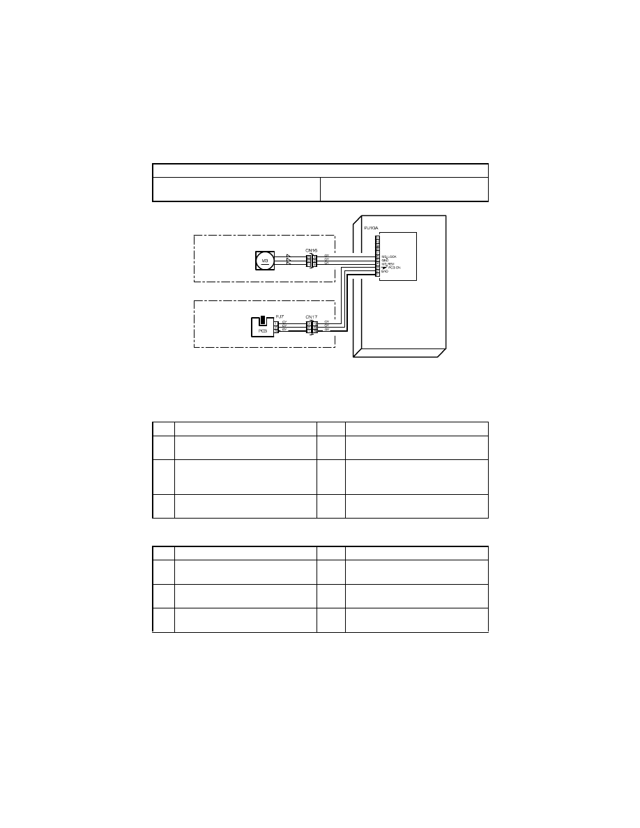
T-16
3-4.
Misfeed at Fusing Unit J3
Misfeed at Fusing Unit J3 Troubleshooting Procedures
• Paper is at a stop at the Fusing Unit.
• Paper is at a stop at the paper exit section.
Relevant Electrical Parts
Exit Paper Sensor (PC3)
Fusing Cooling Fan Motor (M3)
Master Board (PWB-A)
Step
Check
Result
Action
1
Fusing guide plate is dirty, scratchy,
deformed, worn, or damaged.
YES
• Clean or change.
2
Fusing Paper Separator Fingers are
dirty, scratchy, deformed, or worn.
YES
• Clean or change the Fusing Paper
Separator Fingers, or change
spring.
3
Fusing Rollers are dirty, scratchy,
deformed, or worn.
YES
• Clean or change.
Step
Check
Result
Action
1
Exit guide plate is dirty, scratchy,
deformed, worn, or damaged.
YES
• Clean or change.
2
Transport Roller is dirty, scratchy,
deformed, or worn.
YES
• Clean or change.
3
Exit Roller/Rolls are dirty, scratchy,
deformed, or worn.
YES
• Clean or change.
PC3 ANODE
PWB-A
Master Board
PAPER EXIT SECTION
FUSING SECTION
Fusing Cooling
Fan Motor
Exit Paper
Sensor
4022T511AA

T-17
Step
Check
Result
Action
4
Exit Paper Sensor (PC3) is opera-
tional.
<Check Procedure>
Check voltage across a Master Board
(copier: PWB-A) pin and GND when
the sensor is blocked.
• Voltage across PJ10A-3 and GND
When blocked: DC5 V
When unblocked: DC0 V
NO
• Change Exit Paper Sensor (PC3).
YES
• Change Master Board (copier:
PWB-A).

T-18
4.
MALFUNCTION
The copier’s CPU is equipped with a self-diagnostics function that, on detecting a malfunc-
tion, gives the corresponding malfunction code on the Display.
4-1.
Detection Timing by Malfunction Code
Code
Description
Detection Timing
C0000
Main Motor malfunc-
tion
• The Main Motor (M1) Lock signal remains HIGH for a
continuous 1-sec. period at any time 1 sec. after the
Main Motor has started turning.
C0045
Fusing Cooling Fan
Motor malfunction
• The Fusing Cooling Fan Motor (M3) Lock signal
remains HIGH for a continuous 1-sec. period while the
Fusing Cooling Fan Motor is turning at full speed or
decelerated speed.
C004E
Power Supply Cool-
ing Fan Motor mal-
function
• The Power Supply Cooling Fan Motor (M4) Lock sig-
nal remains HIGH for a continuous 1-sec. period while
the Power Supply Cooling Fan Motor Remote signal
remains ON (for full-speed rotation) or OFF (for decel-
erated-speed rotation).
C0070
Toner Replenishing
Motor malfunction
• The Toner Bottle Home Position Sensor (PC7) outputs
a HIGH signal for a continuous 3.5-sec. period while
the Toner Bottle is turning.
• The Toner Bottle Home Position Sensor (PC7) outputs
a LOW signal for a continuous 2-sec. period while the
Toner Bottle is turning.
C0210
Abnormal image
transfer voltage
• The image transfer voltage remains more than 100 V
for a continuous given period of time while the PC
Drum remains stationary.
C03FF
Improperly set Adjust
Mode 11
• An incorrect setting is made of Adjust 11.
C0500
Warm-up failure
• It takes the surface temperature of the Left Fusing
Roller more than 35 sec. to reach 100 °C since the
start of a warm-up cycle.
• It takes the surface temperature of the Left Fusing
Roller more than 25 sec. to reach 140 °C after it has
reached 100 °C.
• It takes more than 20 sec. for the warm-up cycle to be
completed after the surface temperature of the Left
Fusing Roller has reached 140 °C.
C0510
Abnormally low fus-
ing temperature
• The surface temperature of the Left Fusing Roller
remains lower than 120 °C for a given period of time
while the copier is in a standby state.
• The surface temperature of the Left Fusing Roller
remains lower than 120 °C for a given period of time
during a print cycle.
C0520
Abnormally high fus-
ing temperature
The surface temperature of the Left Fusing Roller
remains higher than 240 °C for a given period of time.

T-19
Code
Description
Detection Timing
C0650
Faulty Scanner Home
Position Sensor
• The Scanner Home Position Sensor (PC6) does not
go from HIGH to LOW when the Scanner Motor (M5)
is energized for a given number of steps after the
sequence to bring the Scanner back to its home posi-
tion has been started at the end of a scan motion and
during re-shading.
• The Scanner Home Position Sensor (PC6) does not
go from LOW to HIGH when the Scanner Motor (M5)
is energized for a given number of steps after a scan
motion has been started at the end of a Scanner
Home Position Sensor home check scan motion and
during re-shading.
C0B60
Bin Switching Motor
malfunction
If the Upper Home Position Sensor is LOW during an ini-
tial operation:
• The Lower Home Position Sensor (PC33) is LOW
when the Bin Switching Motor (M1) starts turning for-
ward.
• If the Lower Home Position Sensor (PC33) does not
go LOW at a time 2.5 sec. after the Bin Switching
Motor (M1) has started turning forward, the Bin
Switching Motor is kept deenergized for a given
period of time and then energized again to turn back-
ward. The Upper Home Position Sensor (PC32) does
not go LOW after the motor has started turning back-
ward.
• The Upper Home Position Sensor (PC32) does not go
HIGH at a time 1 sec. after the Bin Switching Motor
(M1) has started turning forward.
• When the Lower Home Position Sensor (PC33) goes
LOW, the Bin Switching Motor (M1) starts turning
backward. The Upper Home Position Sensor (PC32)
does not go LOW at a time 2.5 sec. after the motor
has started turning backward.
• When the Lower Home Position Sensor (PC33) goes
LOW, the Bin Switching Motor (M1) starts turning
backward. The Lower Home Position Sensor (PC33)
does not go HIGH at a time 1 sec. after the motor has
started turning backward.
If the Lower Home Position Sensor is LOW during an ini-
tial operation:
• The Upper Home Position Sensor (PC32) does not go
LOW at a time 2.5 sec. after the Bin Switching Motor
(M1) has started turning backward.
• The Lower Home Position Sensor (PC33) does not go
HIGH at a time 1 sec. after the Bin Switching Motor
(M1) has started turning backward.

T-20
Code
Description
Detection Timing
C0B60
Bin Switching Motor
malfunction
If both the Upper Home Position Sensor and the Lower
Home Position Sensor are HIGH during an initial opera-
tion:
• If the Lower Home Position Sensor (PC33) does not
go LOW at a time 2.5 sec. after the Bin Switching
Motor (M1) has started turning forward, the Bin
Switching Motor is kept deenergized for a given
period of time and then energized again to turn back-
ward. The Upper Home Position Sensor (PC32) does
not go LOW after the motor has started turning back-
ward.
• When the Lower Home Position Sensor (PC33) goes
LOW, the Bin Switching Motor (M1) starts turning
backward. The Upper Home Position Sensor (PC32)
does not go LOW at a time 2.5 sec. after the motor
has started turning backward.
• When the Lower Home Position Sensor (PC33) goes
LOW, the Bin Switching Motor (M1) starts turning
backward. The Lower Home Position Sensor (PC33)
does not go HIGH at a time 1 sec. after the motor has
started turning backward.
C0B80
Shift Motor malfunc-
tion
• The Home Sensor (S31) is LOW at a timing immedi-
ately before the Shift Motor (M1) starts turning back-
ward.
• The Home Sensor (S31) is LOW after the lapse of a
given period of time after the Shift Motor (M1) has
started turning backward.
C0F32
Faulty ATDC Sensor
• The measurement taken by the ATDC Sensor (UN1)
at a time 2.5 sec. after the Main Motor (M1) has
started turning is less than 3 % (greater than 4.98 V).
• The measurement taken by the ATDC Sensor (UN1)
at a time 2.5 sec. after the Main Motor (M1) has
started turning is 19 % or more (1.41 V or less).
C0F33
Improperly adjusted
ATDC Sensor
• The adjustment of the ATDC control voltage is not
completed within 1 sec. after sampling has started of
the ATDC Sensor (UN1) as part of an operation of
ATDC Sensor Automatic Adjustment.
• The ATDC Sensor control voltage falls outside the
range of 5.39 V to 8.15 V during an operation of ATDC
Sensor Automatic Adjustment.
C1038
Engine connection
failure
Master Board (PWB-A) to Control Board (PWB-C) con-
nection failure
• There is no acknowledge signal transmitted from the
Master Board (PWB-A) to Control Board (PWB-C) for
1.5 sec. or more.
• An error command signal is transmitted from the Con-
trol Board (PWB-C) to Master Board (PWB-A).
• An error status signal is transmitted from the Master
Board (PWB-A) to Control Board (PWB-C).

T-21
Code
Description
Detection Timing
C1200
Faulty ASIC/memory
ASIC/memory (for image and control) fault
• A write or read error occurs with SRAM on the Control
Board (PWB-C).
C1300
Polygon Motor mal-
function
Startup failure
• A LOW Polygon Motor (M2) Lock signal is not
detected within a given period of time that begins 1
sec. after the Polygon Motor has started turning.
Lock signal fault: Unstable after the first Lock signal has
been detected
• For a period of 1 sec. after the first LOW Polygon
Motor (M2) Lock signal (first Lock) has been detected,
the next LOW Polygon Motor Lock signal is not
detected.
Lock signal fault: Lock signal out-of-timing
• A LOW Polygon Motor (M2) Lock signal is not
detected for a continuous given period of time while
the rotation of the Polygon Motor remains stabilized.
Faulty Lock signal
• A LOW Polygon Motor (M2) Lock signal is detected for
a given period of time or more when the Polygon
Motor remains deenergized.
C13F0
Faulty HSYNC
Laser scanning system malfunction
• The SOS Sensor does not detect a rising edge of
SOS within a given period of time after the Polygon
Motor (M2) has started turning and a laser output has
been started.
• The SOS Sensor detects no rising edges of SOS
while VIA (image area control) is ON.
C1468
Faulty EEPROM
EEPROM fault
• Data cannot be written in EEPROM.
• Data stored in EEPROM is wrong.
C14A3
IR fluorescent lamp
fault
The Exposure Lamp (LA2) of the Scanner fails to turn
ON.
• The intensity of the Exposure Lamp is a predeter-
mined value or less during shading and re-shading.
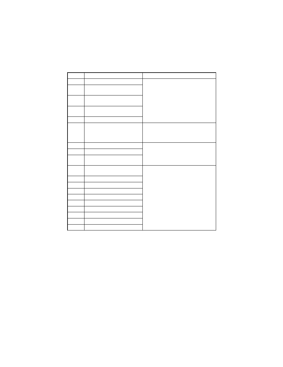
T-22
4-2.
Resetting Procedure by Malfunction Code
Code
Description
Resetting Procedure
C0000
Main Motor malfunction
• Turn OFF and ON the Power Switch.
C0045
Fusing Cooling Fan Motor mal-
function
C004E
Power Supply Cooling Fan Motor
malfunction
C0070
Toner Replenishing Motor mal-
function
C0210
Abnormal image transfer voltage
C03FF
Improperly set Adjust Mode 11
• Set Adjust Mode 11 correctly and then
turn OFF and ON the Power Switch.
• For details, see SWITCHES ON PWBs/
TECH. REP. SETTINGS.
C0500
Warm-up failure
• Turn ON the Power Switch with the Stop
key held down.
C0510
Abnormally low fusing temperature
C0520
Abnormally high fusing tempera-
ture
C0650
Faulty Scanner Home Position
Sensor
• Turn OFF and ON the Power Switch.
C0B60
Bin Switching Motor malfunction
C0F32
Faulty ATDC Sensor
C0F33
Improperly adjusted ATDC Sensor
C1038
Engine connection failure
C1200
Faulty ASIC/memory
C1300
Polygon Motor malfunction
C13F0
Faulty HSYNC
C1468
Faulty EEPROM
C14A3
IR fluorescent lamp fault
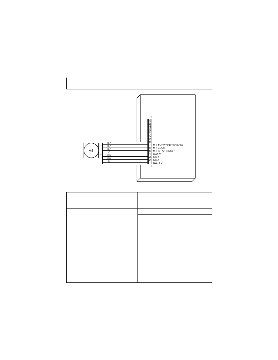
T-23
4-3.
Troubleshooting Procedures by Malfunction Code
(1)
C0000: Main Motor malfunction
Relevant Electrical Parts
Main Motor (M1)
Master Board (copier: PWB-A)
Step
Check
Result
Action
1
Main Motor (M1) turns when the Start
key is pressed.
NO
• Check for overload.
2
The following voltage is supplied to
the Main Motor (M1) when the Start
key is pressed.
Check voltage across a Master Board
(copier: PWB-A) pin and GND when
the Start key is pressed.
• Voltage across PJ7A-6 and GND
DC5 V when Main Motor (M1) is in
standby state
DC0 V when Main Motor (M1) is
energized
• Voltage across PJ7A-5 and GND
DC5 V when Main Motor (M1) is in
standby state
DC0 V when Main Motor (M1) is
energized
NO
• Change Main Motor (M1).
YES
• Change Master Board (copier:
PWB-A).
PJ4
PJ7A
1
2
3
4
5
6
7
PWB-A
Master Board
Main Motor
4022T525AA
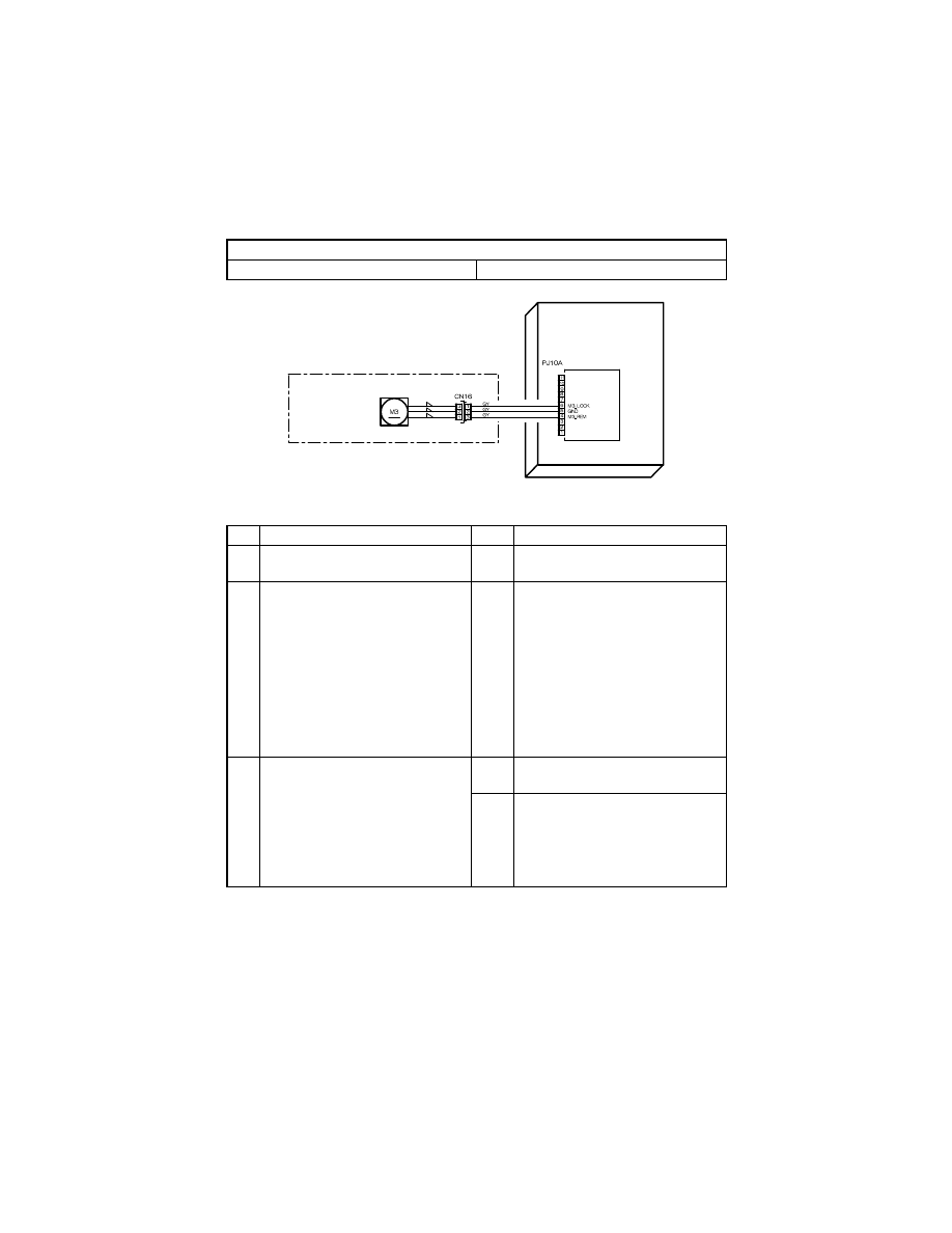
T-24
(2)
C0045: Fusing Cooling Fan Motor malfunction
Relevant Electrical Parts
Fusing Cooling Fan Motor (M3)
Master Board (copier: PWB-A)
Step
Check
Result
Action
1
Fusing Cooling Fan Motor (M3) turns
when the Power Switch is turned ON.
NO
• Check for overload.
2
The following voltage is supplied to
the Fusing Cooling Fan Motor (M3).
<Check Procedure>
Check voltage across a Master Board
(copier: PWB-A) pin and GND when
the Power Switch is turned ON.
• Voltage across PJ10A-4 and GND
DC8 V during rotation at deceler-
ated speed
DC24 V during rotation at full
speed
YES
• Change Fusing Cooling Fan Motor
(M3).
3
The following voltage is supplied to
the Fusing Cooling Fan Motor (M3).
<Check Procedure>
Check voltage across a Master Board
(copier: PWB-A) pin and GND when
the Power Switch is turned ON.
• Voltage across PJ10A-6 and GND
DC0 V when energized
NO
• Change Fusing Cooling Fan Motor
(M3).
YES
• Change Master Board (copier:
PWB-A).
PWB-A
Master Board
FUSING SECTION
Fusing Cooling
Fan Motor
4022T526AA
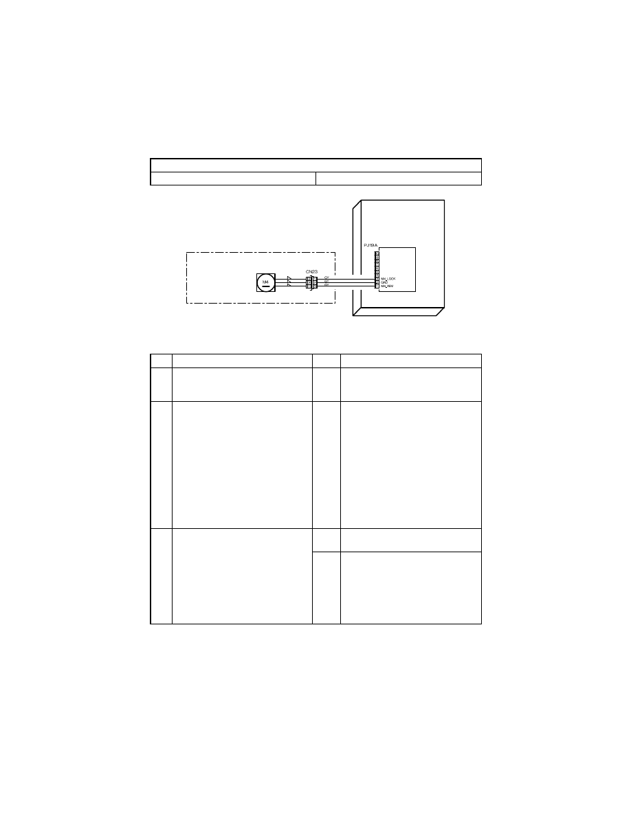
T-25
(3)
C004E: Power Supply Cooling Fan Motor malfunction
Relevant Electrical Parts
Power Supply Cooling Fan Motor (M4)
Master Board (copier: PWB-A)
Step
Check
Result
Action
1
Power Supply Cooling Fan Motor
(M4) turns when the Power Switch is
turned ON.
NO
• Check for overload.
2
The following voltage is supplied to
the Power Supply Cooling Fan Motor
(M4).
<Check Procedure>
Check voltage across a Master Board
(copier: PWB-A) pin and GND when
the Power Switch is turned ON.
• Voltage across PJ19A-1 and GND
DC8 V during rotation at deceler-
ated speed
DC24 V during rotation at full
speed
YES
• Change Power Supply Cooling Fan
Motor (M4).
3
The following voltage is supplied to
the Power Supply Cooling Fan Motor
(M4).
<Check Procedure>
Check voltage across a Master Board
(copier: PWB-A) pin and GND when
the Power Switch is turned ON.
• Voltage across PJ19A-3 and GND
DC0 V when energized
NO
• Change Power Supply Cooling Fan
Motor (M4).
YES
• Change Master Board (copier:
PWB-A).
PWB-A
Master Board
POWER SUPPLY SECTION
Power Supply
Cooling Fan Motor
4022T527AA
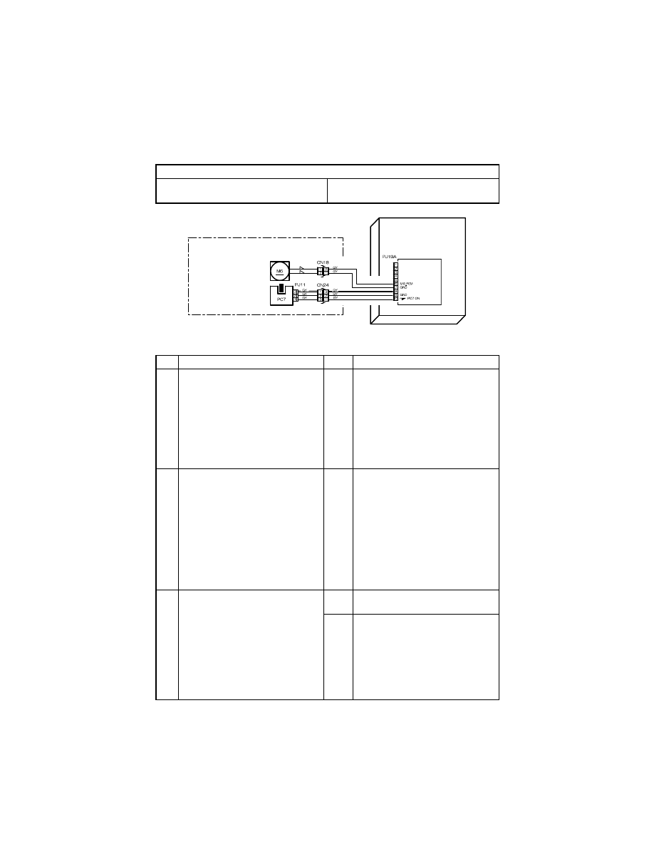
T-26
(4)
C0070: Toner Replenishing Motor malfunction
Relevant Electrical Parts
Toner Replenishing Motor (M6)
Toner Bottle Home Position Sensor (PC7)
Master Board (copier: PWB-A)
Step
Check
Result
Action
1
The coupling of the Toner Hopper
turns as the Toner Replenishing
Motor (M6) turns.
<Check Procedure>
• Disengage the Toner Bottle
Release Lever.
• Turn the Toner Bottle a half turn by
hand.
• Turn ON the Power Switch.
NO
• Check for overload.
2
The Toner Bottle Home Position Sen-
sor (PC7) is operational.
<Check Procedure>
Check voltage across a Master Board
(copier: PWB-A) pin and GND when
the Toner Replenishing Motor (M6)
turns.
• Voltage across PJ19A-10 and
GND
DC0 V when unblocked
DC5 V when blocked
NO
• Change Toner Bottle Home Posi-
tion Sensor (PC7).
3
The following voltage is supplied to
the Toner Replenishing Motor (M6).
<Check Procedure>
Check voltage across a Master Board
(copier: PWB-A) pin and GND when
the Toner Replenishing Motor (M6)
turns.
• Voltage across PJ19A-6 and GND
DC0 V when deenergized
DC24 V when energized
YES
• Change Toner Replenishing Motor
(M6).
NO
• Change Master Board (copier:
PWB-A).
PC7 ANODE
PWB-A
Master Board
DEVELOPING SECTION
Toner Replenishing
Motor
Toner Bottle Home
Position Sensor
4022T528AA
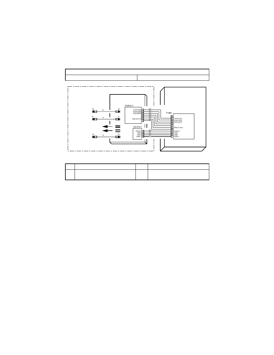
T-27
(5)
C0210: Abnormal image transfer voltage
Relevant Electrical Parts
High Voltage Unit (HV1)
Master Board (copier: PWB-A)
Step
Check
Result
Action
1
• C0210 reappears when the Power
Switch is turned OFF and ON.
YES
• Change High Voltage Unit (HV1).
• Change Master Board (PWB-A).
PWB-A
Master Board
DEVELOPING SECTION
HV1
High Voltage Unit
Developing Bias
Image Transfer
VG Voltage
Charge Neutralizing Cloth
Photo Conductor
Not Use
P.C/I.T._REM
P.C/I.T._REM
I.T.Control
I.T.Control
I.T.Voltage Monitor
I.T.Voltage Monitor
4022T529AA
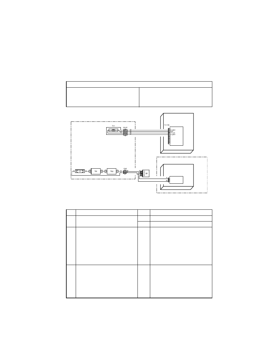
T-28
(6)
C0500: Warm-up failure
C0510: Abnormally low fusing temperature
C0520: Abnormally high fusing temperature
C0500: Warm-up failure; C0510: Abnormally low fusing temperature
Relevant Electrical Parts
Fusing Heater Lamp (H1)
Thermistor (TH1)
Thermoswitch 1 (TS1)
Thermoswitch 1 (TS2)
Fusing Unit Interlock Switch (S2)
DC Power Supply (PU1)
Master Board (copier: PWB-A)
Step
Check
Result
Action
1
• Fusing Heater Lamp (H1) turns
ON.
YES
• Go to step 3.
NO
• Go to step 2.
2
Fusing Heater Lamp (H1) is open-cir-
cuited.
<Check Procedure>
Check the resistance across both
ends of the Fusing Heater Lamp
(H1).
The Fusing Heater Lamp is open-cir-
cuited if the resistance is infinity.
YES
• Change Fusing Heater Lamp (H1).
3
Thermoswitch 1/2 (TS1/TS2) is oper-
ational.
<Check Procedure>
Check the resistance across both
ends of the Thermoswitch 1/2 (TS1/
TS2). The Thermoswitch 1 is open-
circuited if the resistance is infinity.
NO
• Change Thermoswitch 1 (TS1).
• Change Thermoswitch 2 (TS2).
CN2PU1
HEATER_L
HEATER_N
R
R
PWB-A
Master Board
PU1
DC Power Supply
FUSING SECTION
POWER SUPPLY SECTION
Fusing Heater
Lamp
Thermistor
Thermo-
switch 1
Fusing Unit
Interlock Switch
Not Use
Not Use
Thermo-
switch 2
4022T530AA
T-29
C0520: Abnormally high fusing temperature
Step
Check
Result
Action
4
Fusing Unit Interlock Switch (S2) is
operational.
<Check Procedure>
Check continuity across terminals
when the Fusing Unit Interlock
Switch (S2) is turned ON.
• Across S2-1A and S2-1B
• Across S2-2A and S2-2B
NO
• Change Fusing Unit Interlock
Switch (S2).
YES
• Change DC Power Supply (PU1).
5
Thermistor (TH1) is open-circuited.
<Check Procedure>
Check the resistance across CN15-2
and CN15-3 on the Fusing Unit side
with CN15 disconnected.
The Thermistor is open-circuited if
the resistance is infinity.
YES
• Change Thermistor (TH1).
6
The following voltages are supplied
from the Master Board (copier: PWB-
A).
<Check Procedure>
Check voltage across a Master Board
(copier: PWB-A) pin and GND when
the Power Switch is turned ON.
• Voltage across PJ10A-7 and GND
DC24 V when Fusing Heater Lamp
(H1) is OFF
DC0 V when Fusing Heater Lamp
(H1) is ON
• Voltage across PJ10A-10 and
GND
DC24 V when Fusing Heater Lamp
(H1) is OFF
DC0 V when Fusing Heater Lamp
(H1) is ON
NO
• Change Master Board (copier:
PWB-A).
Step
Check
Result
Action
1
Thermistor (TH1) is dirty.
YES
• Clean Thermistor (TH1).
2
Thermistor (TH1) is open-circuited.
<Check Procedure>
Check the resistance across CN15-2
and CN15-3 on the Fusing Unit side
with CN15 disconnected.
The Thermistor is open-circuited if
the resistance is infinity.
YES
• Change Thermistor (TH1).
NO
• Change Master Board (copier:
PWB-A).
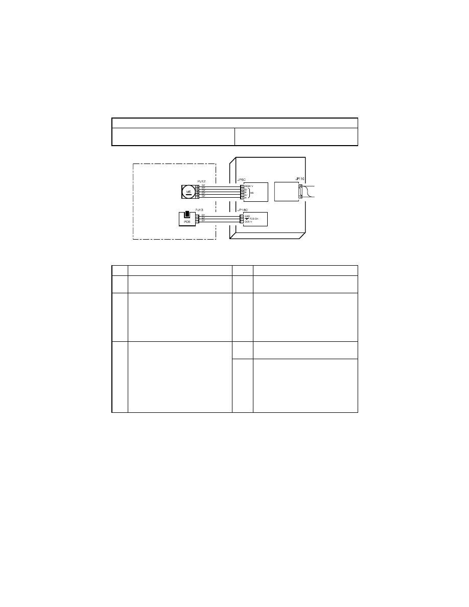
T-30
(7)
C0650: Faulty Scanner Home Position Sensor
Relevant Electrical Parts
Scanner Motor (M5)
Scanner Home Position Sensor (PC6)
Control Board (copier: PWB-C)
Step
Check
Result
Action
1
Scanner Motor (M5) turns when the
Power Switch is turned ON.
NO
• Change Scanner Motor (M5).
2
Scanner moves smoothly.
<Check Procedure>
Gently move the Scanner by hand to
check for smooth operation.
NO
• Remove foreign matter and other
obstacle.
• Clean the Scanner rails.
• Clean or change the Scanner bush-
ings.
• Reinstall Scanner.
3
Scanner Home Position Sensor
(PC6) is operational.
<Check Procedure>
Check voltage across a Control
Board (copier: PWB-C) pin and GND
when the sensor is blocked.
• Voltage across PJ18C-2 and GND
DC5 V when unblocked
DC0 V when blocked
NO
• Change Scanner Home Position
Sensor (PC6).
YES
• Change Control Board (PWB-C).
PWB-C
Contorol Board
IR SECTION
Scanner
Moter
Scanner Home
Position Sensor
PWB-A
Master
Board
4022T531AA
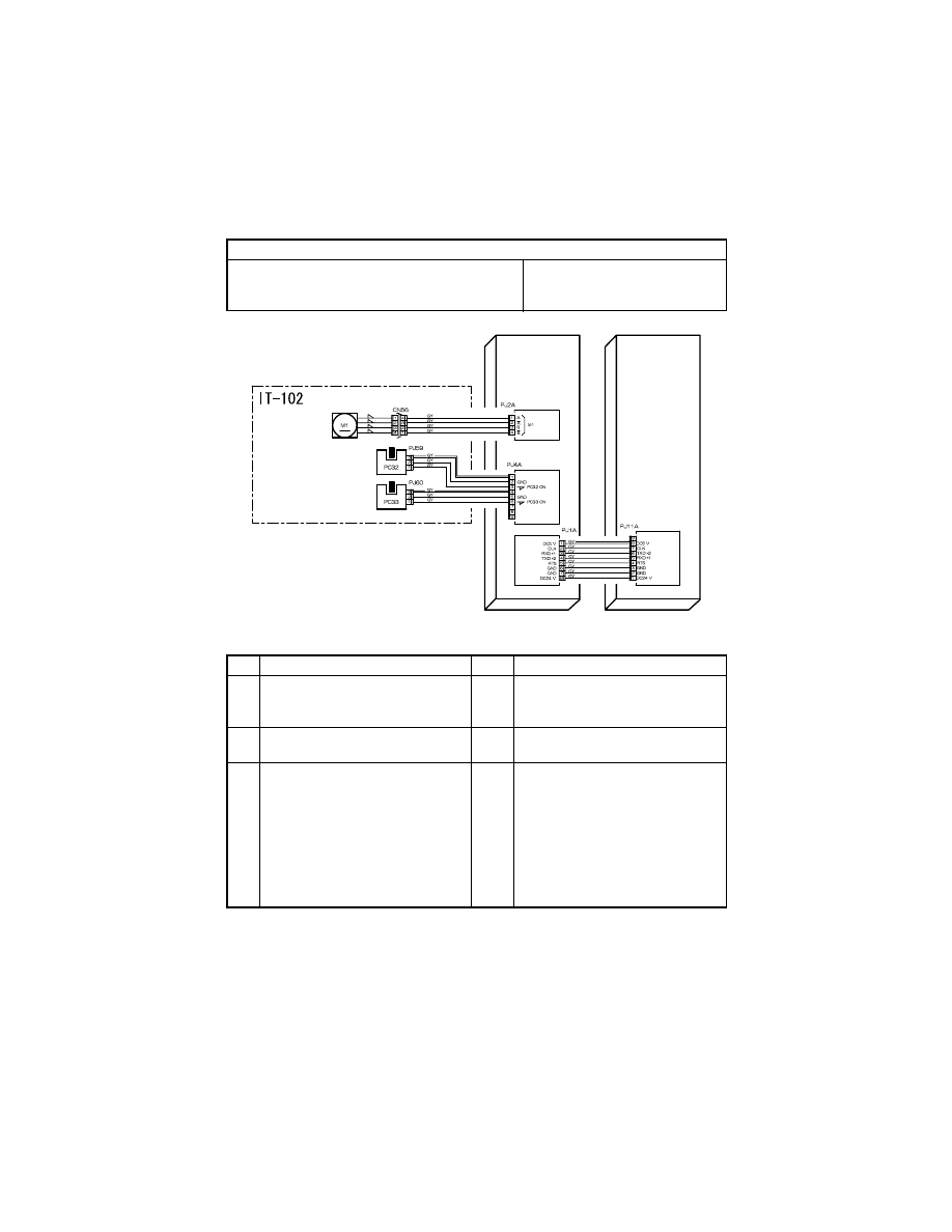
T-31
(8)
C0B60: Bin Switching Motor malfunction
Relevant Electrical Parts
Bin Switching Motor (IT-102: M1)
Upper Home Position Sensor (IT-102: PC32)
Lower Home Position Sensor (IT-102: PC33)
Main Board (IT-102: PWB-A)
Master Board (copier: PWB-A)
Step
Check
Result
Action
1
Bin Switching Motor (IT-102: M1)
turns when the Power Switch is
turned ON.
NO
• Change Bin Switching Motor (IT-
102: M1).
2
Tray is moved as the Bin Switching
Motor (IT-102: M1) operates.
NO
• Reinstall motor unit.
3
Upper Home Position Sensor (IT-102:
PC32) is operational.
<Check Procedure>
Check voltage across a Main Board
(IT-102: PWB-A) pin and GND when
the sensor is blocked.
• Voltage across PJ4A-3 and GND
DC0 V when unblocked
DC5 V when blocked
NO
• Change Upper Home Position Sen-
sor (PC32).
PC32 ANODE
PC33 ANODE
Not Use
PWB-A
Master
Board
IT-102
PWB-A
Main Board
Bin Switching
Motor
Upper Home
Position Sensor
Lower Home
Position Sensor
4022T532AA

T-32
Step
Check
Result
Action
4
Lower Home Position Sensor (IT-102:
PC33) is operational.
<Check Procedure>
Check voltage across a Main Board
(IT-102: PWB-A) pin and GND when
the sensor is blocked.
• Voltage across PJ4A-6 and GND
DC0 V when unblocked
DC5 V when blocked
NO
• Change Lower Home Position Sen-
sor (PC33).
YES
• Change Master Board (copier:
PWB-A).
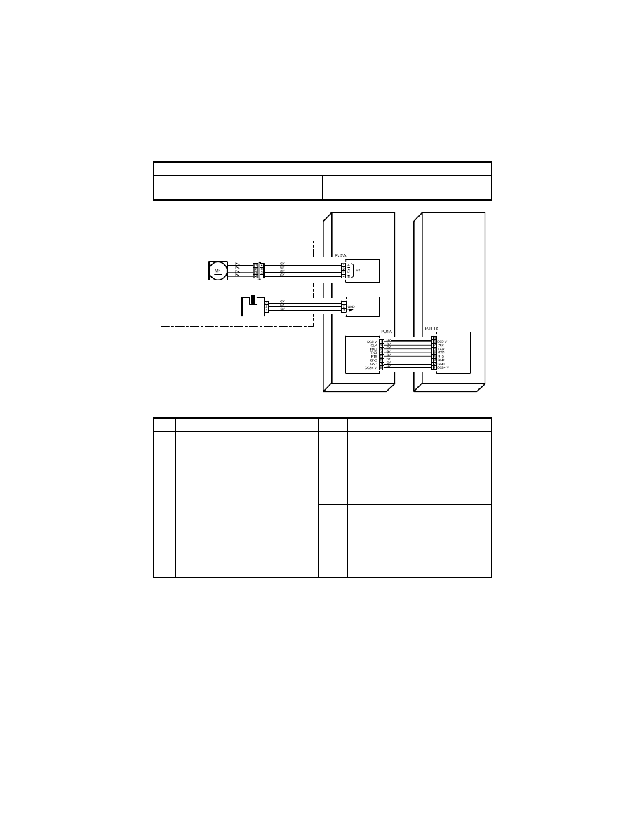
T-33
(9)
C0B80 Shift Motor malfunction
Relevant Electrical Parts
Shift Motor (IS-101: M1)
Home Sensor (IS-101: S31)
Main Board (IS-101: PWB-A)
Master Board (copier: PWB-A)
Step
Check
Result
Action
1
Shift Motor (IS-101: M1) turns when
the Power Switch is turned ON.
NO
• Change Shift Motor (IS-101: M1).
2
Exit Roller operates as the Shift
Motor (IS-101: M1) is energized.
NO
• Reinstall motor unit.
3
Home Sensor (IS-101: S31) is opera-
tional.
<Check Procedure>
Check voltage across a Main Board
(IS-101: PWB-A) pin and GND when
the sensor is blocked.
• Voltage across PJ3A-3 and GND
DC5 V when blocked
DC0 V when unblocked
NO
• Change Home Sensor (IS-101:
S31).
YES
• Change Master Board (copier:
PWB-A).
S31 ON
S31 ANODE
PJ3A
PWB-A
Master
Board
IS-101
PWB-A
Main Board
Not Use
IS-101
Shift Motor
Home Sensor
CN55
PJ58
S31
4022T536AA
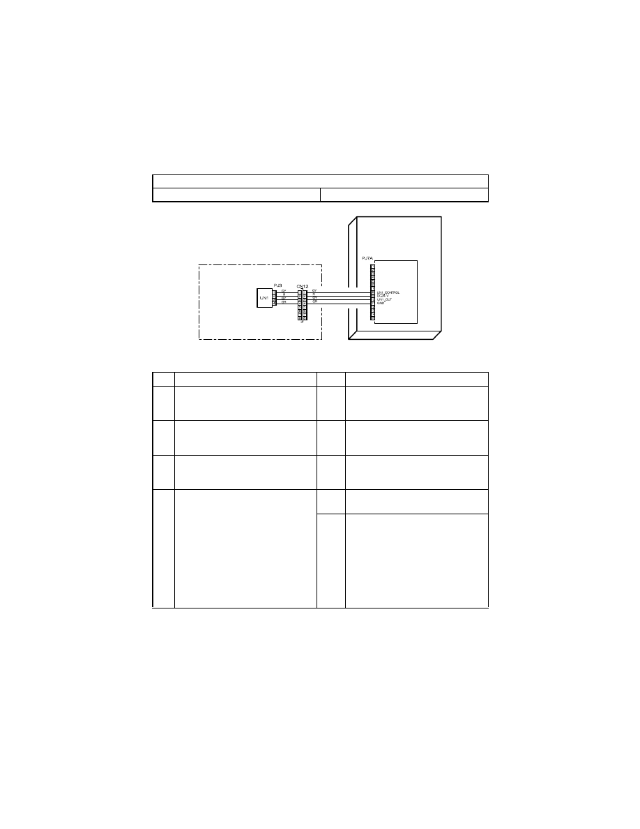
T-34
(10) C0F32: Faulty ATDC Sensor
C0F33: Improperly adjusted ATDC Sensor
Relevant Electrical Parts
ATDC Sensor (UN1)
Master Board (copier: PWB-A)
Step
Check
Result
Action
1
Developer is not even in the Devel-
oper Mixing Chamber.
YES
• Gently swing the IU in the horizon-
tal direction to even out developer
in the Developer Mixing Chamber.
2
ATDC Sensor (UN1) is dirty with for-
eign matter (such as paper dust)
other than developer.
YES
• Clean ATDC Sensor (UN1).
3
Foreign matter (such as paper dust)
is trapped in the Developer Mixing
Chamber.
YES
• Remove foreign matter from the
Developer Mixing Chamber.
4
The following voltages are supplied
from the Master Board (copier: PWB-
A).
<Check Procedure>
Check voltage across a Master Board
pin and GND when the Power Switch
is turned ON.
• DC5.39 V to 8.15 V across PJ7A-8
and GND
• DC1.41 V to 4.98 V across PJ7A-
10 and GND
YES
• Change ATDC Sensor (UN1) and
developer.
NO
• Change Master Board (copier:
PWB-A).
PWB-A
Master Board
DEVELOPING SECTION
ATDC Sensor
4022T533AA
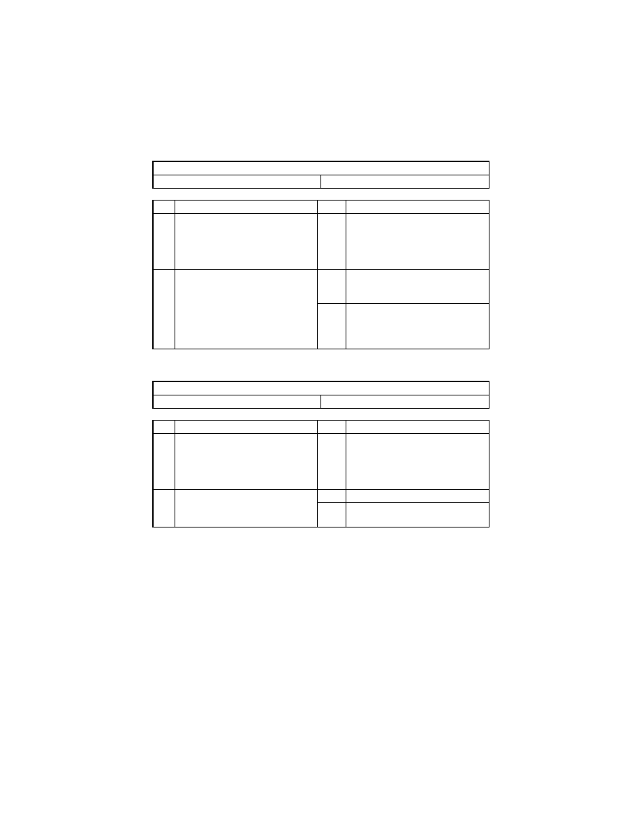
T-35
(11) C1038: Engine connection failure
(12) C1200: Faulty ASIC/memory
Relevant Electrical Parts
Master Board (copier: PWB-A)
Control Board (copier: PWB-C)
Step
Check
Result
Action
1
C1038 reappears when the copier is
turned OFF and ON again.
<Check Procedure>
Turn OFF and ON the Power Switch
to check to see if C1038 reappears.
YES
• Go to step 2.
2
The connection between Master
Board (copier: PWB-A) and Control
Board (copier: PWB-C) is loose.
YES
• Make good connection between
Master Board (copier: PWB-A) and
Control Board (copier: PWB-C).
NO
• Change Control Board (copier:
PWB-C).
• Change Master Board (copier:
PWB-A).
Relevant Electrical Parts
Control Board (copier: PWB-C)
Step
Check
Result
Action
1
C1200 reappears when the copier is
turned OFF and ON again.
<Check Procedure>
Turn OFF and ON the Power Switch
to check to see if C1200 reappears.
YES
• Go to step 2.
2
Memory (U8) on Control Board
(copier: PWB-C) is loose.
YES
• Reinstall memory (U8).
NO
• Change Control Board (copier:
PWB-C).
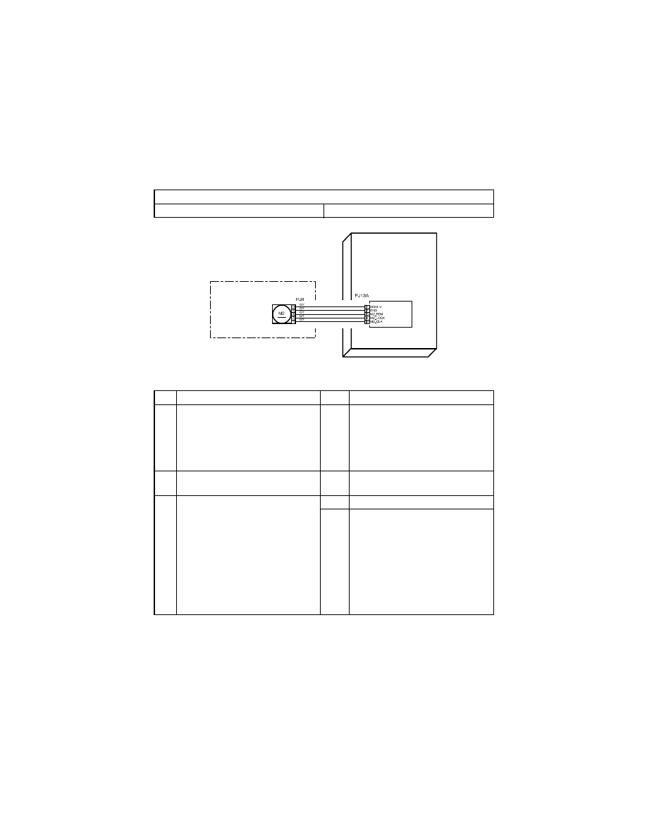
T-36
(13) C1300: Polygon Motor malfunction (startup failure, Lock signal failure, faulty
Lock signal)
C13F0: Faulty HSYNC
Relevant Electrical Parts
Polygon Motor (M2)
Master Board (copier: PWB-A)
Step
Check
Result
Action
1
C1300/C13F0 reappears when the
copier is turned OFF and ON again.
<Check Procedure>
Turn OFF and ON the Power Switch
to check to see if C1300/C13F0 reap-
pears.
YES
• Go to step 2.
2
Polygon Motor (M2) connector PJ13A
is loose.
YES
• Reconnect connector PJ13A.
3
The following voltage is supplied to
the Polygon Motor (M2).
<Check Procedure>
Check voltage across a Master Board
(copier: PWB-A) and GND when the
Start key is pressed.
• Voltage across PJ13A-3 and GND
DC5 V while Polygon Motor (M2) is
in standby state
DC0 V when Polygon Motor (M2) is
energized
YES
• Change PH Unit.
NO
• Change Master Board (copier:
PWB-A).
IR/PH SECTION
Polygon Motor
PWB-A
Master Board
4022T534AA

T-37
(14) C1468: Faulty EEPROM
Relevant Electrical Parts
Control Board (copier: PWB-C)
Step
Check
Result
Action
1
C1468 reappears when the copier is
turned OFF and ON again.
<Check Procedure>
Turn OFF and ON the Power Switch
to check to see if C1468 reappears.
YES
• Go to step 2.
2
Memory (U29) on Control Board
(copier: PWB-C) is loose.
YES
• Reinstall memory (U29).
NO
• Change Control Board (copier:
PWB-C).
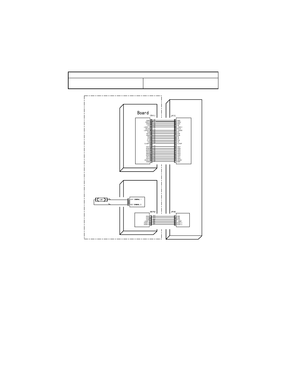
T-38
(15) C14A3: IR fluorescent lamp fault
Relevant Electrical Parts
Exposure Lamp (LA2)
Inverter Board (copier: PU2)
Control Board (copier: PWB-C)
PWB-J
CCD
IR SECTION
Exposure Lamp
PU2
Inverter Board
PWB-C
Control Board
Not Use
Not Use
Not Use
Not Use
4022T535AA

T-39
Step
Check
Result
Action
1
Exposure Lamp turns ON when the
Power Switch is turned ON.
NO
• Go to step 3.
2
Exposure Lamp is abnormally lit
(flickers or abnormally dark) when
the Power Switch is turned ON.
NO
• Go to step 4.
3
Inverter Board (copier: PU2) connec-
tor is loose.
YES
• Reconnect.
NO
• Change Exposure Lamp (LA2).
4
CCD Board (copier: PWB-J) connec-
tor is loose.
YES
• Reconnect.
5
The following voltage is supplied from
the Control Board (copier: PWB-C).
<Check Procedure>
Check voltage across a Control
Board (copier: PWB-C) pin and GND
when the Power Switch is turned ON.
• Voltage across JP16C-4 and GND
DC24 V when Exposure Lamp
(LA2) is OFF
DC0 V when Exposure Lamp (LA2)
is ON
YES
• Change Inverter Board (PU2).
NO
• Change Control Board (copier:
PWB-C).
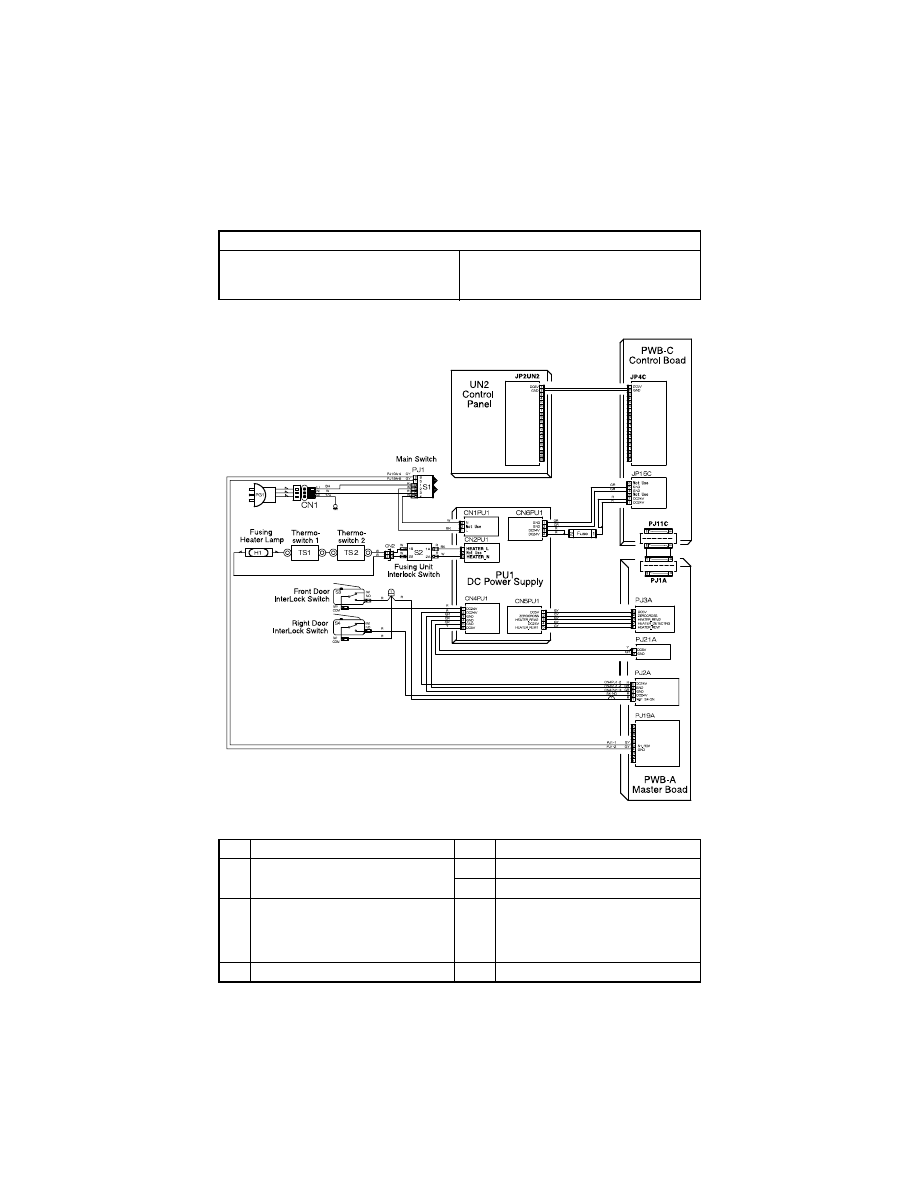
T-40
(16) The copier does not turn ON.
Relevant Electrical Parts
Power Switch (S1)
DC Power Supply (PU1)
Control Panel (UN2)
Fuse (F3)
Control Board (copier: PWB-C)
Master Board (copier: PWB-A)
Step
Check
Result
Action
1
A malfunction code appears when
the Power Switch is turned ON.
YES
• Go to step 2.
NO
• Go to step 3.
2
The malfunction is temporarily reset
when the Power Switch is turned
OFF and ON with the Stop key held
down.
YES
• Perform the troubleshooting proce-
dure according to the malfunction
code.
3
Check fuse for short.
YES
• Change Fuse (F3).
4022T545AA

T-41
Step
Check
Result
Action
4
Power supply voltage check
<Check Procedure>
Check voltage across pins of DC Power Sup-
ply (PU1) when the Power Switch is turned
ON.
• Voltage across CN1PU1-1 and CN1PU1-3
AC0 V when the Power Switch is OFF
Rated AC voltage when the Power Switch is
turned ON
NO
• Check wall outlet for volt-
age.
• Check power cord for con-
tinuity.
• Check Power Switch.
5
Check of output of DC24 V to Control Board
(copier: PWB-C)
<Check Procedure>
Check voltage across a Control Board (copier:
PWB-C) pin and GND when the Power Switch
is turned ON.
• Voltage across JP15C-1 and GND
• Voltage across JP15C-2 and GND
DC0 V when the Power Switch is OFF
DC24 V when the Power Switch is turned
ON
NO
• Check Front Door Inter-
lock Switch (S3).
• Check Right Door Inter-
lock Switch (S4).
• Change DC power Supply
(PU1).
6
Check of output of DC24 V to Master Board
(copier: PWB-A)
<Check Procedure>
Check voltage across a Master Board (copier:
PWB-A) pin and GND when the Power Switch
is turned ON.
• Voltage across PJ2A-2 and GND
DC0 V when the Power Switch is OFF
DC24 V when the Power Switch is turned
ON
NO
• Check Front Door Inter-
lock Switch (S3).
• Check Right Door Inter-
lock Switch (S4).
• Change DC power Supply
(PU1).
7
Check of output of DC 5 V to Master Board
(copier: PWB-A)
<Check Procedure>
Check voltage across a Master Board (copier:
PWB-A) pin and GND when the Power Switch
is turned ON.
• Voltage across PJ21A-1 and GND
DC0 V when the Power Switch is OFF
DC24 V when the Power Switch is turned
ON
NO
• Change DC power Supply
(PU1).
8
Check of output of DC5 V to control panel
(UN2)
<Check Procedure>
Check voltage across a Control Board (copier:
PWB-C) pin and GND when the Power Switch
is turned ON.
• Voltage across JP4C-1 and GND
DC0 V when the Power Switch is OFF
DC5 V when the Power Switch is turned ON
NO
• Check Control Board
(copier: PWB-C).
• Change Master Board
(copier: PWB-A).
• Change DC power Supply
(PU1).
YES
• Change control panel
(UN2).

T-42
5.
IMAGE FAILURE
5-1.
Image Failure Troubleshooting
• In this chapter, troubleshooting is divided into “initial checks” and “troubleshooting proce-
dures classified by image failures.”
• If any image failure has occurred, first make the initial checks, then proceed to the corre-
sponding image failure troubleshooting procedure.
5-2.
Initial Checks
• Determine if the failure is attributable to a basic cause or causes.
Section
Step
Check
Result
Action
Installation
site
1
The installation site complies
with the requirements speci-
fied in “PRECAUTIONS FOR
INSTALLATION” contained in
GENERAL.
NO
• Change the installation site.
Paper
2
Paper meets product specifi-
cations.
NO
• Change paper for one that
meets specifications.
• Instruct user to use paper
that meets specifications and
is recommended.
3
Paper is damp.
YES
• Change paper for one that is
dry.
Then, instruct user to use
paper that meets specifica-
tions and in how to store
paper.
Original
4
Original is placed correctly.
NO
• Reposition original.
• Instruct user in how to place
original correctly.
5
Original is written in light pen-
cil.
YES
• Change original.
• Instruct user to use original
with appropriate image den-
sity.
6
Original is transparent (OHP
transparencies, etc.).
YES
• Change original.
• Instruct user to use originals
that meet specifications.
7
Original Glass is dirty.
YES
• Clean Original Glass.
8
Original Glass is scratchy.
YES
• Change Original Glass.
PM parts
9
The PM parts relating to
image formation have reached
the end of cleaning/replace-
ment cycles.
YES
• Clean PM parts.
• Change PM parts.
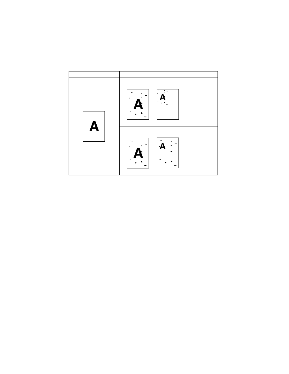
T-43
• Determine if the failure is attributable to an input system (IR) or output system (engine).
Check
Result
Action
Copy made at a reduced
ratio.
Input system
Output system
Original
1177T03YA
Full-size copy
Reduced copy
1177T04YA
Full-size copy
Reduced copy
1177T05YA
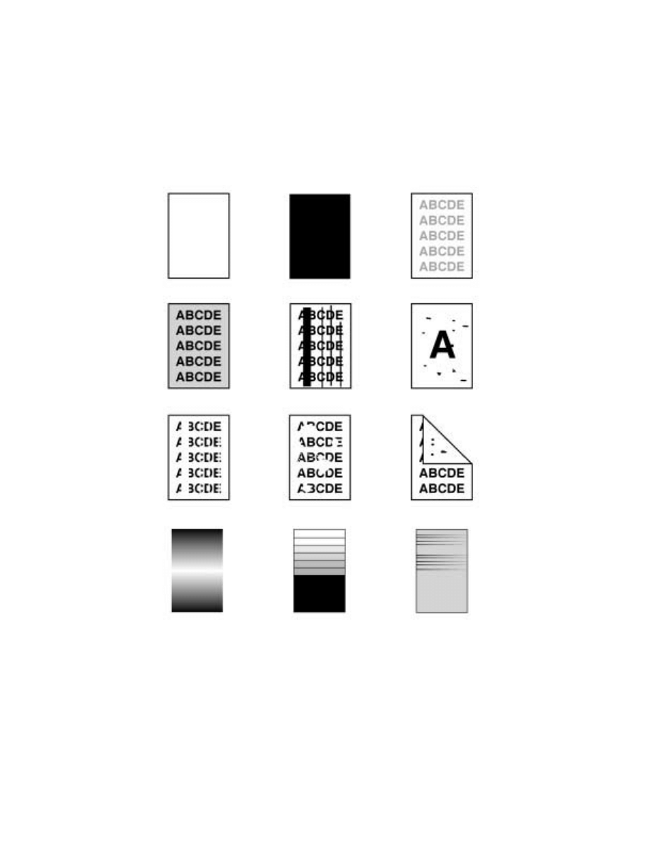
T-44
5-3.
Image Failure Samples
1. Blank copy
2. Black copy
3. Low image density
4. Foggy background or rough
image
5. Black streaks or bands
6. Black spots
7. Blank streaks or bands
8. Void areas
9. Smear on back
10. Uneven image density
11. Gradation reproduc-
tion failure
12. Periodically
uneven image
4022T542
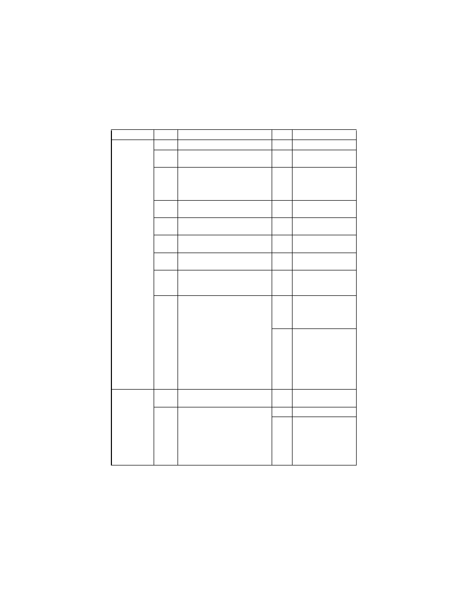
T-45
5-4.
Troubleshooting Procedures by Image Failure
(1)
Blank copy
Section
Step
Check
Result
Action
Output system
1
Imaging Unit is installed correctly.
NO
• Reinstall.
2
Connector between the Imaging
Unit and copier is dirty.
YES
• Clean.
3
PH Shutter (located along the
laser path between the PH Unit
and PC Drum) is not in correct
position or malfunctions.
YES
• Correct or reinstall.
4
PH Unit connectors PJ12A and
PJ13A are loose.
YES
• Reconnect.
5
Image Transfer Roller Assy is
installed correctly.
NO
• Reinstall.
6
Image transfer current contact is
dirty, broken, or bent.
YES
• Clean, correct, or
change.
7
Developing bias contact is dirty,
broken, or bent.
YES
• Clean, correct, or
change.
8
High Voltage Unit (HV1) connec-
tors CN1HV1 and CN2HV1 are
loose.
YES
• Reconnect.
9
The following voltage is supplied
from the Master Board (copier:
PWB-A).
<Check Procedure>
Check voltage across a Master
Board pin and GND when the
Start key is pressed.
• Voltage across PJ8A-8 and
GND
DC14 V in standby state
DC0 V when Start key is
pressed
YES
• Change IU.
• Change PH Unit.
• Change High Volt-
age Unit (HV1).
NO
• Change Master
Board (copier:
PWB-A).
Input system
1
CCD Board (PWB-J) connector
JP7C is loose.
YES
• Reconnect.
2
Control Board (copier: PWB-C)
connector PJ1A is loose.
YES
• Reconnect.
NO
• Change Control
Board (copier:
PWB-C).
• Change Master
Board (copier:
PWB-A).
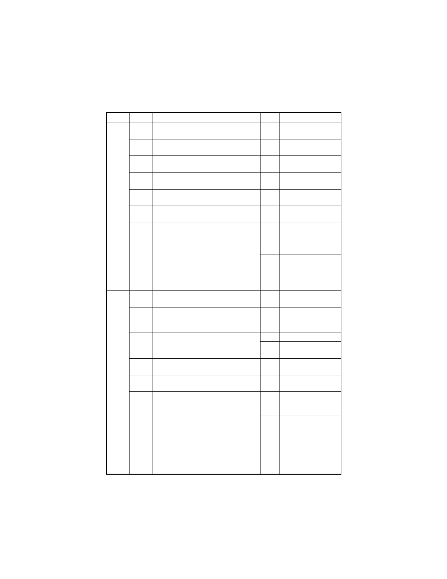
T-46
(2)
Black copy
Section
Step
Check
Result
Action
Output
system
1
PC Drum Charge Corona grid mesh and
Comb Electrode are loose.
YES
• Reinstall.
2
PC Drum Charge Corona contact is dirty,
scratchy, folded, bent, or damaged.
YES
• Correct or change.
3
Grid bias contact is dirty, folded, or bent.
YES
• Clean, correct, or
change.
4
PC Drum ground contact is dirty,
scratchy, bent, or damaged.
YES
• Clean, correct, or
change.
5
High Voltage Unit (HV1) connectors
CN1HV1 and CN2HV1 are loose.
YES
• Reconnect.
6
PH Unit connectors PJ12A and PJ13A
are loose.
YES
• Reconnect.
7
The following voltage is supplied from
the Master Board (copier: PWB-A).
<Check Procedure>
Check voltage across a Master Board
pin and GND when the Start key is
pressed.
• Voltage across PJ8A-8 and GND
DC14 V in standby state
DC0 V when Start key is pressed
YES
• Change IU.
• Change PH Unit.
• Change High Volt-
age Unit (HV1).
NO
• Change Master
Board (copier:
PWB-A).
Input
system
1
Exposure Lamp turns ON when the
Power Switch is turned ON.
NO
Go to step 3.
2
Exposure Lamp is abnormally lit (flickers
or abnormally dark) when the Power
Switch is turned ON.
NO
Go to step 4.
3
Inverter Board (copier: PU2) connector
is loose.
YES
Reconnect.
NO
Change Exposure
Lamp.
4
CCD Board (copier: PWB-J) connector is
loose.
YES
Reconnect.
5
Control Board (copier: PWB-C) connec-
tor PJ1A is loose.
YES
Reconnect.
6
The following voltage is supplied from
the Control Board (copier: PWB-C).
<Check Procedure>
Check voltage across a Control Board
(copier: PWB-C) pin and GND when the
Power Switch is turned ON.
• Voltage across JP16C-4 and GND
DC24 V when Exposure Lamp (LA2) is
OFF
DC0 V when Exposure Lamp (LA2) is
ON
YES
• Change Inverter
Board (PU2).
• Change CCD Unit.
NO
• Change Control
Board (copier:
PWB-C).
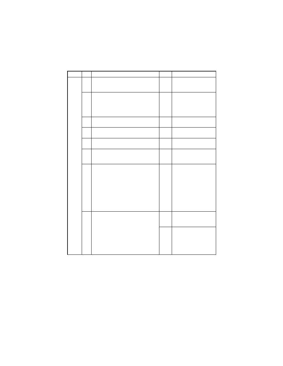
T-47
(3)
Low image density
Section Step
Check
Result
Action
Output
system
1
Image density changes after “Toner
Replenisher” has been run.
• “Toner Replenisher” of Utility
YES
• Replenish the supply of
toner using “Toner
Replenisher.”
2
Image density changes after “ID Adjust-
ment” and “VG Adjustment” have been
made.
YES
• Readjust.
For more details, see
SWITCHES ON PWBs/
TECH. REP. SET-
TINGS.
3
Image transfer current contact is dirty,
folded, or bent.
YES
• Clean, correct, or
change.
4
Developing bias contact is dirty, folded,
or bent.
YES
• Clean, correct, or
change.
5
High Voltage Unit (HV1) connectors
CN1HV1 and CN2HV1 are loose.
YES
• Reconnect.
6
ATDC Sensor (UN1) is dirty with foreign
matter (such as paper dust) other than
developer.
YES
• Clean.
7
The following voltages develop from the
ATDC Sensor (UN1).
<Check Procedure>
Check voltage across a Master Board
pin and GND when the Power Switch is
turned ON.
• DC5.39 V to 8.15 V across PJ7A-8
and GND
• DC1.41 V to 4.98 V across PJ7A-10
and GND
NO
• Change ATDC Sensor
(UN1) and then change
developer.
8
The following voltage is supplied from
the Master Board (copier: PWB-A).
<Check Procedure>
Check voltage across a Master Board
pin and GND when the Start key is
pressed.
• Voltage across PJ8A-8 and GND
DC14 V in standby state
DC0 V when Start key is pressed
YES
• Change IU.
• Change High Voltage
Unit (HV1).
NO
• Change Master Board
(copier: PWB-A).

T-48
Section Step
Check
Result
Action
Input
system
1
Shading sheet reading portion (the por-
tion on the backside of the Original
Glass to which Original Width Scale is
affixed) is dirty.
YES
• Clean.
2
CCD Board (copier: PWB-J) connector
is loose.
YES
• Reconnect.
3
Control Board (copier: PWB-C) connec-
tor PJ1A is loose.
YES
• Reconnect.
NO
• Change Control Board
(copier: PWB-C).
• Change Master Board
(copier: PWB-A).
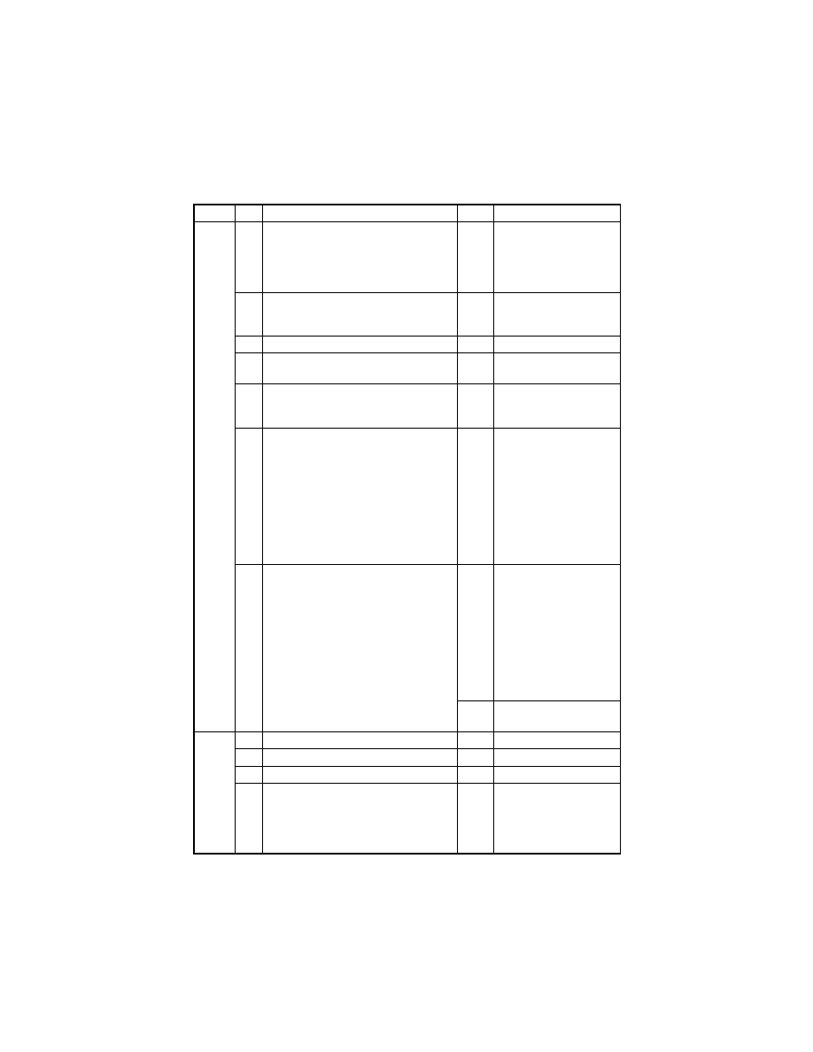
T-49
(4)
Foggy background or rough image
Section Step
Check
Result
Action
Output
system
1
Image condition changes after “ID
Adjustment” and “VG Adjustment” have
been made.
YES
• Readjust.
For more details, see
SWITCHES ON PWBs/
TECH. REP. SET-
TINGS.
2
PC Drum surface and the areas in con-
tact with Ds Collars are dirty with foreign
matter, or deformed or worn.
YES
• Clean or change.
3
Main Erase (LA1) is dirty.
YES
• Clean.
4
Grid bias contact is dirty, scratchy,
deformed, worn, or damaged.
YES
• Clean, correct, or
change.
5
ATDC Sensor (UN1) is dirty with foreign
matter (such as paper dust) other than
developer.
YES
• Clean.
6
The following voltages develop from the
ATDC Sensor (UN1).
<Check Procedure>
Check voltage across a Master Board
pin and GND when the Power Switch is
turned ON.
• DC5.39 V to 8.15 V across PJ7A-8
and GND
• DC1.41 V to 4.98 V across PJ7A-10
and GND
NO
• Change ATDC Sensor
(UN1) and then change
developer.
7
The following voltage is supplied from
the Master Board (copier: PWB-A).
<Check Procedure>
Check voltage across a Master Board
pin and GND when the Start key is
pressed.
• Voltage across PJ8A-8 and GND
DC14 V in standby state
DC0 V when Start key is pressed
YES
• Adjust Db.
For details, see DIS/
REASSEMBLY,
ADJUSTMENT.
• Change Main Erase
(LA1).
• Change PC Drum.
• Change IU.
• Change High Voltage
Unit (HV1).
NO
• Change Master Board
(copier: PWB-A).
Input
system
1
Original Glass is dirty.
YES
• Clean.
2
Scanner mirrors are dirty.
YES
• Clean.
3
Exposure Lamp (LA2) is dirty.
YES
• Clean.
4
CCD Unit lens and CCD surface are
dirty.
<Check Procedure>
Remove lens cover to check for possible
contamination.
YES
• Clean.

T-50
Section Step
Check
Result
Action
Input
system
5
Exposure Lamp is abnormally lit (flickers
or abnormally dark) when the Start key
is pressed.
NO
• Go to step 7.
6
Inverter Board (copier: PU2) connector
CN1PU2 is loose.
YES
• Reconnect.
NO
• Change Exposure
Lamp (LA2).
7
CCD Board (copier: PWB-J) connector
PJ7C is loose.
YES
• Reconnect.
NO
• Change Inverter Board
(PU2).
• Change Control Board
(copier: PWB-C).
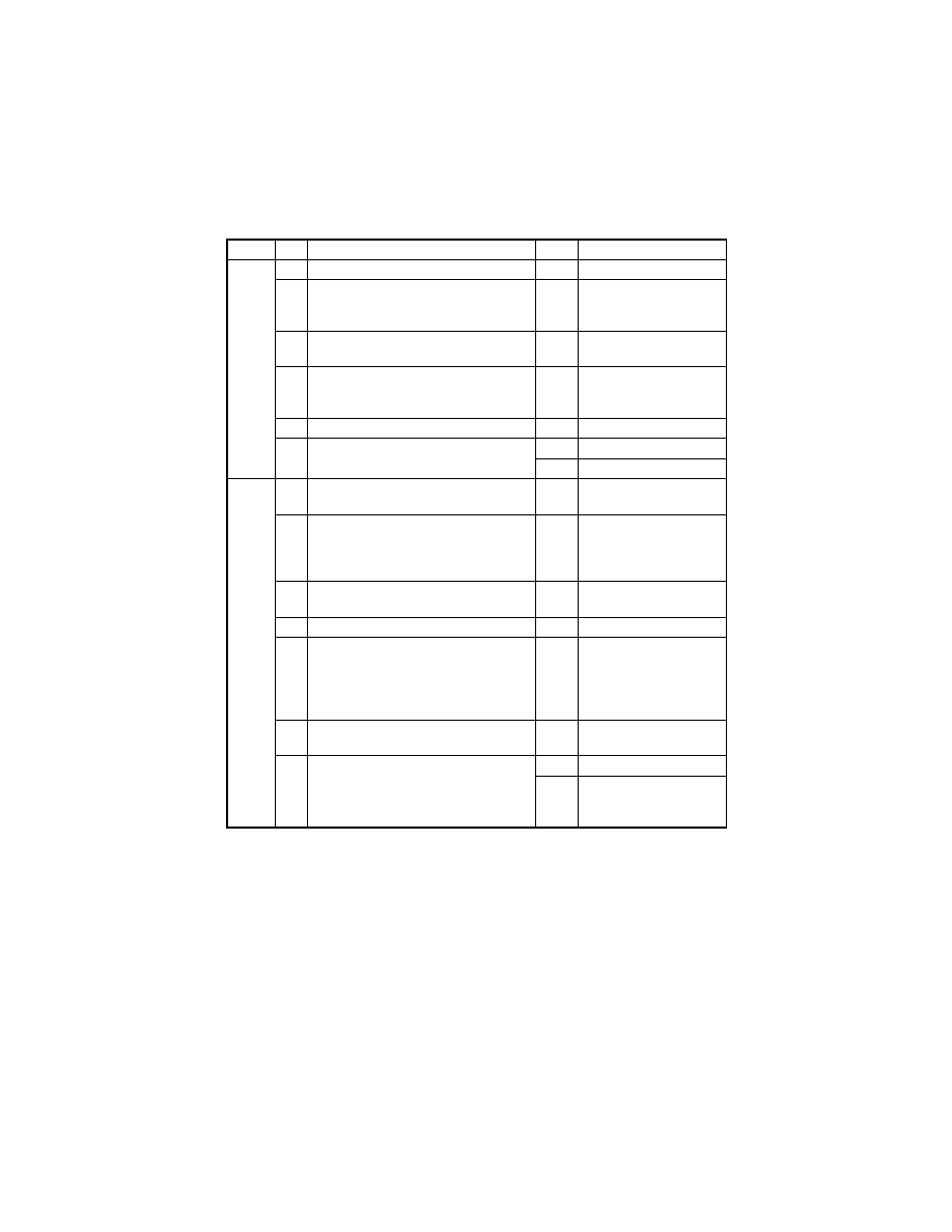
T-51
(5)
Black streaks or bands
Section Step
Check
Result
Action
Output
system
1
PC Drum is dirty or scratchy.
YES
• Clean or change.
2
Foreign matter (such as paper dust)
sticks to the Cleaning Blade of IU or the
blade curves upward.
YES
• Remove foreign mat-
ter, correct, or change.
3
DB of IU is plugged with foreign matter
(such as paper dust).
YES
• Remove foreign matter.
4
PC Drum Charge Corona grid mesh and
Comb Electrode are dirty, scratchy,
deformed, damaged, or out of position.
YES
• Clean or change.
5
Left Fusing Roller is dirty or scratchy.
YES
• Clean or change.
6
PH window of the PH Unit is dirty or
scratchy.
YES
• Clean or change.
NO
• Change IU.
Input
system
1
Original Glass is dirty, scratchy, worn, or
damaged.
YES
• Clean or change.
2
Shading sheet reading portion (the por-
tion on the backside of the Original
Glass to which Original Width Scale is
affixed) is dirty.
YES
• Clean.
3
Scanner mirrors are dirty, scratchy, or
damaged.
YES
• Clean or change.
4
Exposure Lamp (LA2) is dirty.
YES
• Clean or change.
5
CCD Unit lens and CCD surface are
dirty or scratchy.
<Check Procedure>
Remove lens cover to check for possible
contamination.
YES
• Clean or change.
6
CCD Board (copier: PWB-J) connector
is loose.
YES
• Reconnect.
7
Control Board (copier: PWB-C) connec-
tor PJ1A is loose.
YES
• Reconnect.
NO
• Change CCD Unit.
• Change Control Board
(copier: PWB-C).
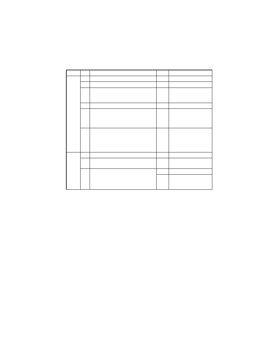
T-52
(6)
Black spots
Section Step
Check
Result
Action
Output
system
1
Toner is present along the paper path.
YES
• Clean.
2
PC Drum is dirty or scratchy.
YES
• Clean or change.
3
Tip of the PC Drum Paper Separator
Finger is dirty, scratchy, deformed, worn,
or damaged.
YES
• Clean or change.
4
Left Fusing Roller is dirty or scratchy.
YES
• Clean or change.
5
Tip of the Fusing Paper Separator Fin-
ger is dirty, scratchy, deformed, worn, or
damaged.
YES
• Clean or change Fus-
ing Paper Separator
Fingers and finger
springs.
6
Image condition changes after “VG
Adjustment” has been made.
YES
• Readjust.
For details, see
SWITCHES ON PWBs/
TECH. REP. SET-
TINGS.
Input
system
1
Original Glass is dirty or scratchy.
YES
• Clean.
2
CCD Board (copier: PWB-J) connector
is loose.
YES
• Reconnect.
3
Control Board (copier: PWB-C) connec-
tor PJ1A is loose.
YES
• Reconnect.
NO
• Change CCD Unit.
• Change Control Board
(copier: PWB-C).
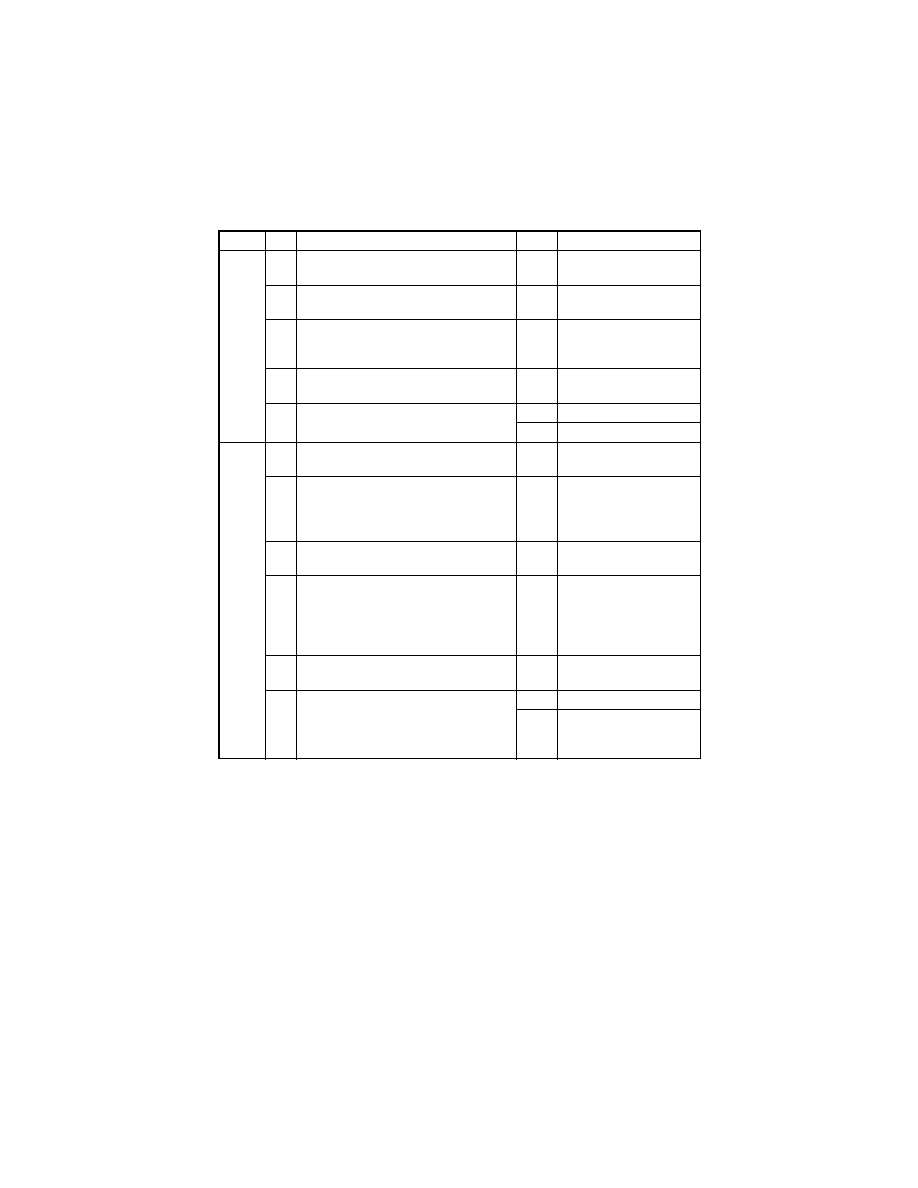
T-53
(7)
Blank streaks or bands
Section Step
Check
Result
Action
Output
system
1
PC Drum ground terminal is dirty,
scratchy, deformed, or damaged.
YES
• Clean, correct, or
change.
2
DB of IU is plugged with foreign matter
(such as paper dust).
YES
• Remove foreign matter.
3
PC Drum Charge Corona grid mesh and
Comb Electrode are dirty, scratchy,
deformed, or damaged.
YES
• Clean, correct, or
change.
4
Post-fusing guide plate is dirty, scratchy,
deformed, worn, or damaged.
YES
• Clean or change.
5
PH window of the PH Unit is dirty,
scratchy, or damaged.
YES
• Clean or change.
NO
• Change IU.
Input
system
1
Original Glass is dirty, scratchy, worn, or
damaged.
YES
• Clean or change.
2
Shading sheet reading portion (the por-
tion on the backside of the Original
Glass to which Original Width Scale is
affixed) is dirty.
YES
• Clean.
3
Scanner mirrors are dirty, scratchy, or
damaged.
YES
• Clean or change.
4
CCD Unit lens and CCD surface are
dirty or scratchy.
<Check Procedure>
Remove lens cover to check for possible
contamination.
YES
• Clean or change.
5
CCD Board (copier: PWB-J) connector
is loose.
YES
• Reconnect.
6
Control Board (copier: PWB-C) connec-
tor PJ1A is loose.
YES
• Reconnect.
NO
• Change CCD Unit.
• Change Control Board
(copier: PWB-C).
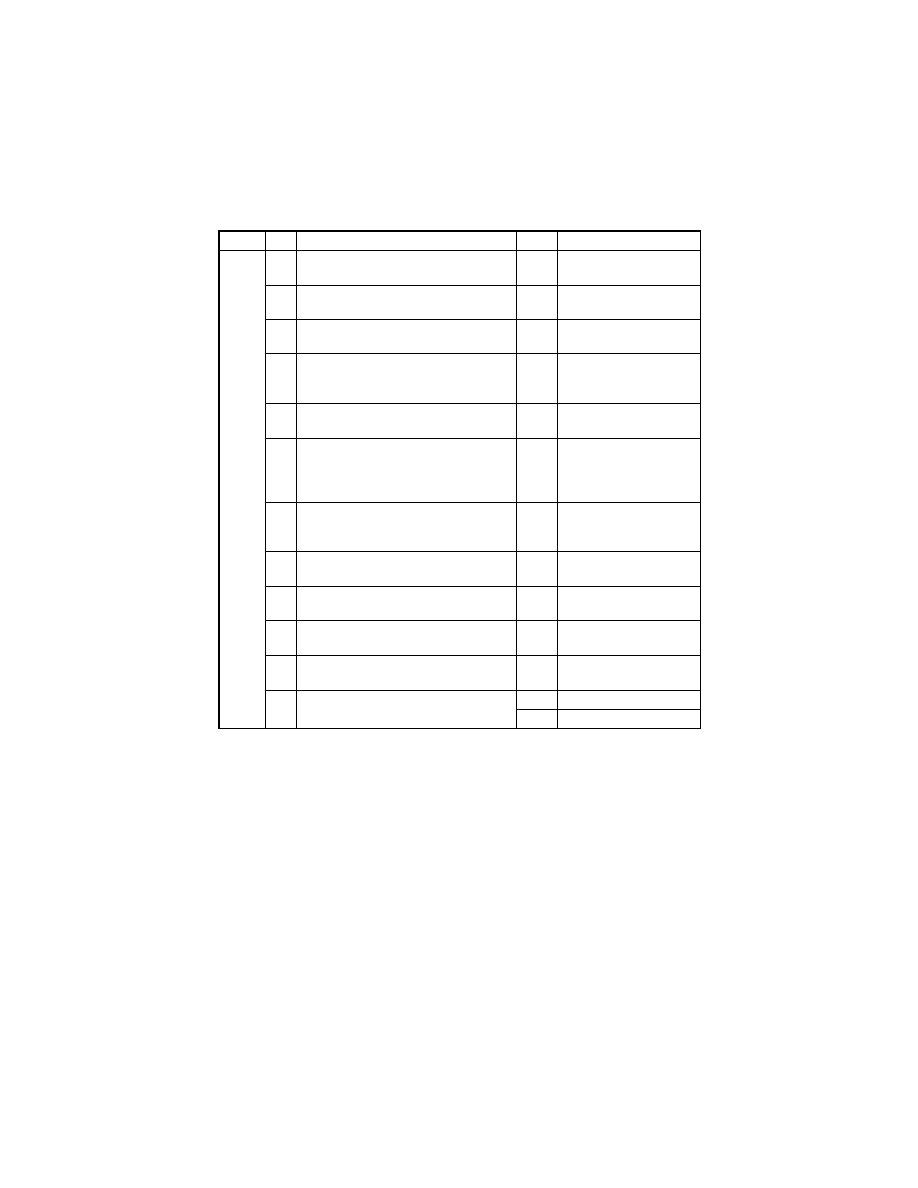
T-54
(8)
Void areas
Section Step
Check
Result
Action
Output
system
1
Foreign matter is present along the
paper path.
YES
• Remove foreign matter.
2
Paper dust plugs up the Paper Dust
Remover.
YES
• Clean or change.
3
PC Drum Charge Corona, grid mesh,
and Comb Electrode are loose.
YES
• Reinstall.
4
PC Drum Charge Corona contact is
dirty, scratchy, deformed, worn, or dam-
aged.
YES
• Clean, correct, or
change.
5
Developing Roller is dirty, scratchy,
deformed, worn, or damaged.
YES
• Clean or change.
6
Toner is even on Sleeve/Magnet Roller.
NO
• Adjust DB.
For details, see DIS/
REASSEMBLY,
ADJUSTMENT.
7
Developer is not even in the Developer
Mixing Chamber of IU.
YES
• Even out developer in
the Developer Mixing
Chamber.
8
DB of IU is plugged with foreign matter
(such as paper dust).
YES
• Remove foreign matter.
9
Image Transfer Roller is dirty, scratchy,
deformed, worn, or damaged.
YES
• Clean, correct, or
change.
10
Image Transfer Roller Assy is installed
correctly.
NO
• Reinstall.
11
Charge Neutralizing Plate is dirty,
scratchy, folded, or bent.
YES
• Clean, correct, or
change.
12
Left Fusing Roller is dirty, scratchy,
deformed, or worn.
YES
• Clean or change.
NO
• Change IU.

T-55
(9)
Smear on back
Section Step
Check
Result
Action
Output
system
1
Toner is spilled over area inside copier.
YES
• Clean interior.
2
Toner is present along the paper path.
YES
• Clean.
3
Right Fusing Roller is dirty, scratchy, or
damaged.
YES
• Clean or change.
4
Image Transfer Roller is dirty.
YES
• Clean or change.
5
Grid bias contact is dirty, scratchy,
deformed, worn, or damaged.
YES
• Clean, correct, or
change.
NO
• Change High Voltage
Unit (HV1).
• Change Master Board
(copier: PWB-A).
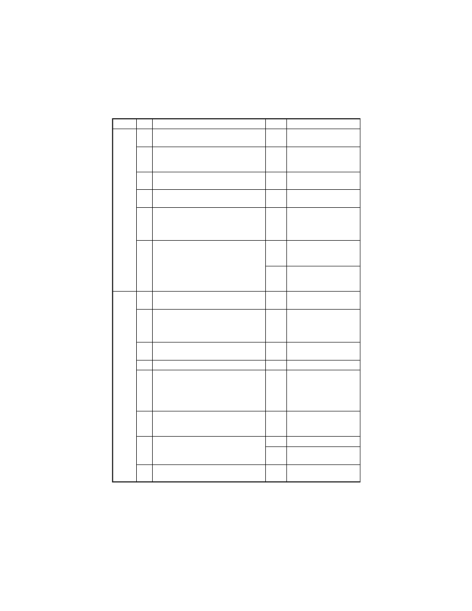
T-56
(10) Uneven image density
Section Step
Check
Result
Action
Output
system
1
PC Drum ground plate is dirty, scratchy,
deformed, worn, or damaged.
YES
• Clean, correct, or
change.
2
PC Drum Charge Corona grid mesh and
Comb Electrode are dirty, scratchy,
deformed, worn, damaged, or loose.
YES
• Clean, correct, or
change.
3
Image Transfer Roller is dirty, scratchy,
deformed, worn, or damaged.
YES
• Clean or change.
4
Sleeve/Magnet Roller is dirty, scratchy,
deformed, worn, or damaged.
YES
• Clean or change.
5
Toner is even on Sleeve/Magnet Roller.
NO
• Adjust DB.
For details, see DIS/
REASSEMBLY,
ADJUSTMENT.
6
Developer is not even in the Developer
Mixing Chamber of IU.
YES
• Even out developer in
the Developer Mixing
Chamber.
NO
• Change IU.
• Change Master Board
(copier: PWB-A).
Input
system
1
Original Glass is dirty, scratchy, worn, or
damaged.
YES
• Clean or change.
2
Shading sheet reading portion (the por-
tion on the backside of the Original
Glass to which Original Width Scale is
affixed) is dirty.
YES
• Clean.
3
Scanner mirrors are dirty, scratchy, or
damaged.
YES
• Clean or change.
4
Exposure Lamp (LA2) is dirty.
YES
• Clean or change.
5
CCD Unit lens and CCD surface are
dirty or scratchy.
<Check Procedure>
Remove lens cover to check for possible
contamination.
YES
• Clean or change.
6
Exposure Lamp is abnormally lit (flickers
or abnormally dark) when the Power
Switch is turned ON.
NO
• Go to step 8.
7
Inverter Board (copier: PU2) connector
CN1PU2 is loose.
YES
• Reconnect.
NO
• Change Exposure
Lamp (LA2).
8
CCD Board (copier: PWB-J) connector
is loose.
YES
• Reconnect.

T-57
Section Step
Check
Result
Action
Input
system
9
Control Board (copier: PWB-C) connec-
tor PJ1A is loose.
YES
• Reconnect.
NO
• Change CCD Unit.
• Change Control Board
(copier: PWB-C).
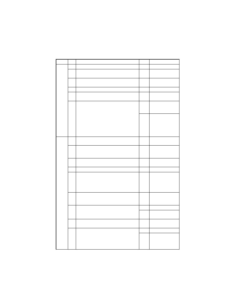
T-58
(11) Gradation reproduction failure
Section Step
Check
Result
Action
Output
system
1
PC Drum is dirty.
YES
• Clean.
2
Image Transfer Roller is dirty, scratchy,
deformed, worn, or damaged.
YES
• Clean or change.
3
PH Unit connectors PJ12A and PJ13A are
loose.
YES
• Reconnect.
4
PH window of PH Unit is dirty.
YES
• Clean.
5
ATDC Sensor (UN1) is dirty with foreign mat-
ter (such as paper dust) other than developer.
YES
• Clean.
6
The following voltages develop from the
ATDC Sensor (UN1).
<Check Procedure>
Check voltage across a Master Board pin and
GND when the Power Switch is turned ON.
• DC5.39 V to 8.15 V across PJ7A-8 and
GND
• DC1.41 V to 4.98 V across PJ7A-10 and
GND
NO
• Change ATDC
Sensor (UN1) and
developer.
YES
• Change Master
Board (copier:
PWB-A).
Input
system
1
Original Glass is dirty, scratchy, worn, or
damaged.
YES
• Clean or change.
2
Shading sheet reading portion (the portion on
the backside of the Original Glass to which
Original Width Scale is affixed) is dirty.
YES
• Clean.
3
Scanner mirrors are dirty, scratchy, or dam-
aged.
YES
• Clean or change.
4
Exposure Lamp (LA2) is dirty.
YES
• Clean or change.
5
CCD Unit lens and CCD surface are dirty or
scratchy.
<Check Procedure>
Remove lens cover to check for possible con-
tamination.
YES
• Clean or change.
6
Exposure Lamp is abnormally lit (flickers or
abnormally dark) when the Start key is
pressed.
NO
• Go to step 8.
7
Inverter Board (copier: PU2) connector
CN1PU2 is loose.
YES
• Reconnect.
NO
• Change Exposure
Lamp (LA2).
8
CCD Board (copier: PWB-J) connector is
loose.
YES
• Reconnect.
9
Control Board (copier: PWB-C) connector
PJ1A is loose.
YES
• Reconnect.
NO
• Change CCD Unit.
• Change Control
Board (copier:
PWB-C).
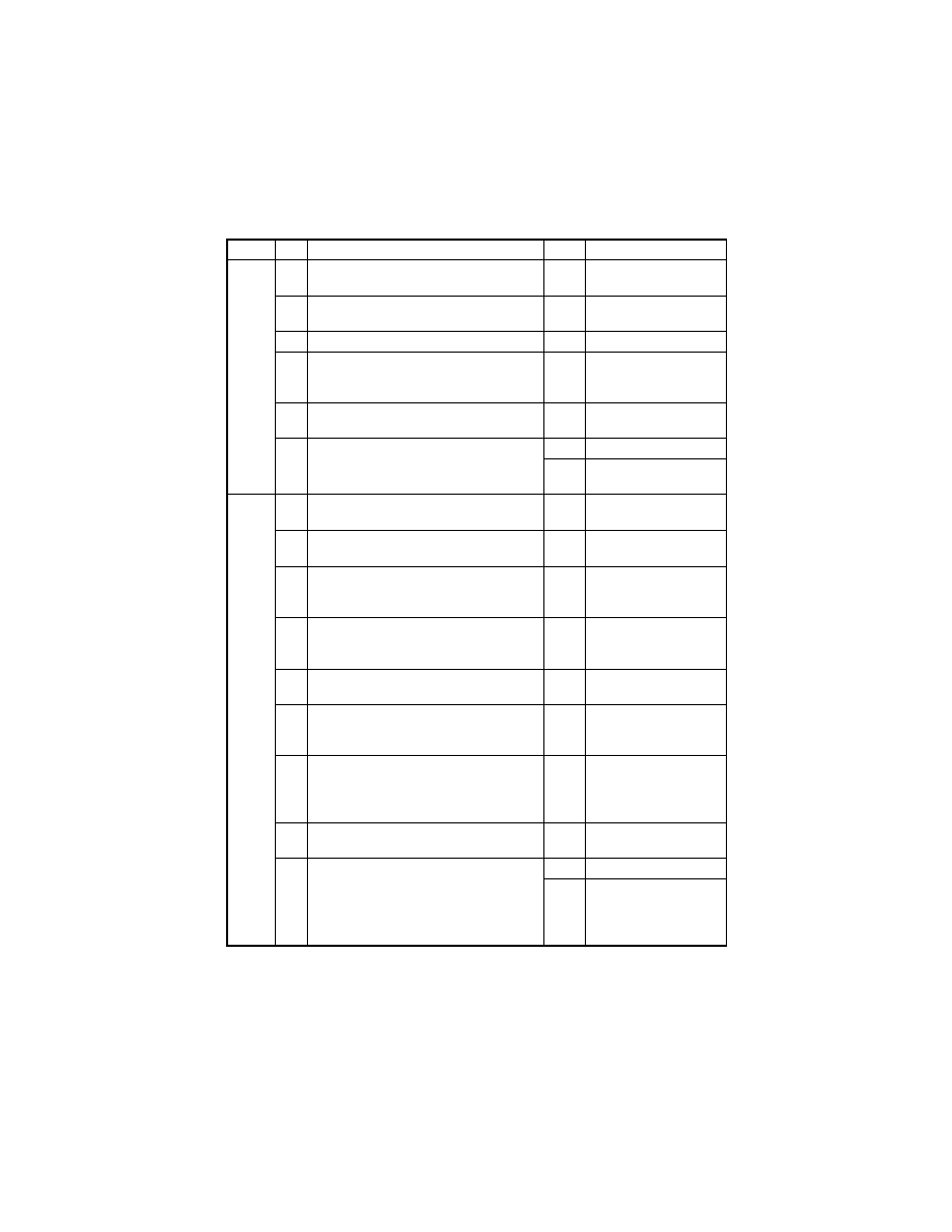
T-59
(12) Periodically uneven image
Section Step
Check
Result
Action
Output
system
1
IU is securely fastened using the dedi-
cated fixing screws.
NO
• Secure in position.
2
PH Unit is securely fastened using the
dedicated fixing screws.
NO
• Secure in position.
3
IU drive mechanism is dirty or damaged.
YES
• Clean or change.
4
PC Drum surfaces in contact with Ds Col-
lars and drive mechanism are dirty,
scratchy, deformed, or worn.
YES
• Clean or change.
5
Synchronizing Roller drive mechanism is
dirty, scratchy, deformed, or worn.
YES
• Clean or change.
6
Fusing Unit drive mechanism is dirty,
scratchy, deformed, or worn.
YES
• Clean or change.
NO
• Change Master Board
(copier: PWB-A).
Input
system
1
Scanner Motor (M5) is securely fastened
using the dedicated fixing screws.
NO
• Secure in position.
2
Scanner Motor (M5) drive mechanism is
dirty or damaged.
YES
• Clean or change.
3
Timing belt of the scanner drive mecha-
nism is dirty with foreign matter or out of
correct position.
YES
• Remove foreign mat-
ter or reinstall belt.
4
Scanner drive mechanism pulley is dirty
with foreign matter, scratchy, deformed,
worn, or damaged.
YES
• Remove foreign mat-
ter or change.
5
Scanner Drive Cables are wound incor-
rectly.
YES
• Re-wind Scanner
Drive Cables.
6
Scanner rails and bushings are dirty with
foreign matter, scratchy, deformed, worn,
or damaged.
YES
• Clean or change.
7
Scanner moves smoothly.
<Check Procedure>
Gently move the Scanner by hand to
check for smooth operation.
NO
• Lubricate the Scan-
ner rails.
• Reinstall Scanner.
8
CCD Board (copier: PWB-J) connector is
loose.
YES
• Reconnect.
9
Control Board (copier: PWB-C) connector
PJ1A is loose.
YES
• Reconnect.
NO
• Change CCD Unit.
• Change Control
Board (copier: PWB-
C).
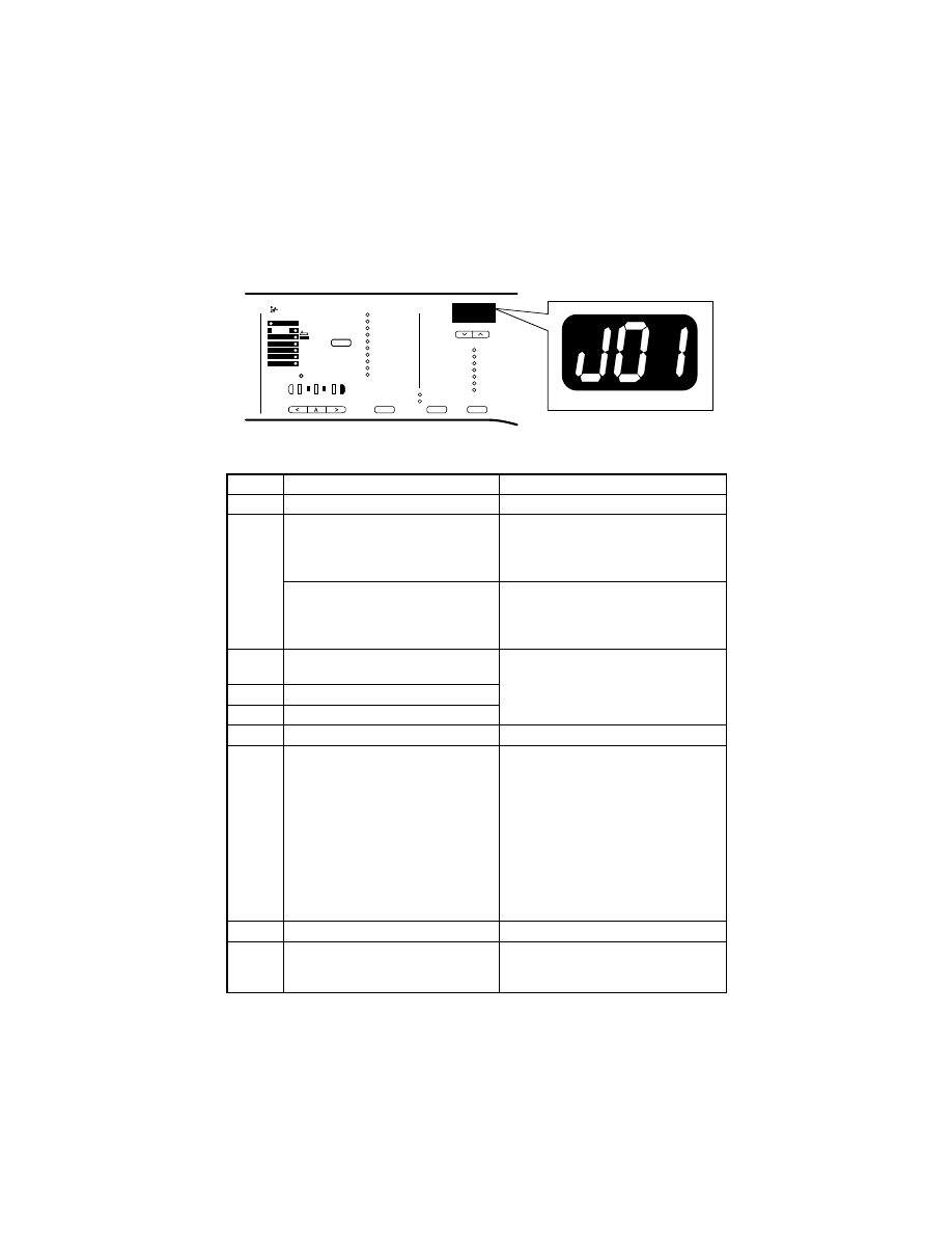
T-60
6.
OTHER ERROR CODES
• When an error that does not fall into the category of paper transport failure or malfunc-
tion, a corresponding error code is displayed in the Display.
Code
Description
Resetting Procedure
tnr
Toner empty stop
• Change Toner Bottle.
nP
Paper size is physically changed of
the paper source currently selected
for use while a copy cycle is being run.
• Load paper of the size originally
loaded in the paper source being
used.
• Turn OFF and ON the Power Switch.
Copier does not find paper of the
appropriate size when a copy cycle is
run using the ADF and in the Mixed
Original and Auto Paper mode.
• Load the paper source with paper of
the appropriate size.
• Turn OFF and ON the Power Switch.
oL
Front Door, Right Door, or Side Door
is open.
• Close the open door or lower the ADF.
oU
ADF is raised.
oA
ADF document take-up door is open.
H11
Scan image memory over
• Turn OFF and ON the Power Switch.
H2
The length of the paper set does not
match that of the paper actually taken
up and fed in.
• Load paper of the correct size again
according to the set paper size.
• Turn OFF and ON the Power Switch.
• For copier tray: Slide out and in the
paper tray in which the size error has
occurred.
• For Manual Bypass Tray: Place paper
in the Manual Bypass Tray.
• For Multiple Bypass Tray: Unload
paper from the Multiple Bypass Tray,
then reload it back again.
H3
IT-102 exit capacity exceeded
• Remove paper that has been fed out.
J9
IT-102 Bin Switching Motor error (Job
Tray is unable to return to its home
position because paper left in the tray)
• Remove paper from the tray.
• Turn OFF and ON the Power Switch.
4022T503AA

T-61
Code
Description
Resetting Procedure
PLG
Plug-In Counter not plugged in
• Plug in the Plug-In Counter.
• Change setting in Security mode.
For details, see SWITCHES ON
PWBs/TECH. REP. SETTINGS.
Err
A numeral outside the specified set-
ting range is entered.
• Automatically reset 1 sec. after the
error display is given.
• Turn OFF and ON the Power Switch.
Blank
Mechanical total counter not con-
nected
• Connect the mechanical total counter
and then turn OFF and ON the Power
Switch.
• Change setting in Security mode.
For details, see SWITCHES ON
PWBs/TECH. REP. SETTINGS.
nc1
Maintenance Counter count value
reached (the set count of the Mainte-
nance Counter is reached)
• Enter a count value again.
For details, see SWITCHES ON
PWBs/TECH. REP. SETTINGS.
nc2
IU life stop mode (the life value of the
Maintenance Counter is reached)
• Initialize the counter value.
For details, see SWITCHES ON
PWBs/TECH. REP. SETTINGS.

T-62
Document Outline
- SERVICE MANUAL FIELD SERVICE
Wyszukiwarka
Podobne podstrony:
Konica Minolta QMS 3260 4032 Parts Manual
hplj 5p 6p service manual vhnlwmi5rxab6ao6bivsrdhllvztpnnomgxi2ma vhnlwmi5rxab6ao6bivsrdhllvztpnnomg
Oberheim Prommer Service Manual
Korg SQ 10 Service Manual
MAC1500 service manual
Kyocera Universal Feeder UF 1 Service Manual
Proview RA783 LCD Service Manual
indesit witp82euy Service Manual
Glow Worm installation and service manual Hideaway 70CF UIS
Proview PZ456 LCD Service Manual
Glow Worm installation and service manual Ultimate 50CF UIS
ewm2000 service manual
Glow Worm installation and service manual Ultimate 60CF UIS
Proview SH770I LCD Service Manual
M23 Service Manual
Glow Worm installation and service manual Glow micron 60
Honda NSR125 '87 Service Manual
więcej podobnych podstron