
MECHANICAL STUDY OF A SHEET METAL FORMING
DIES WEAR
D. Attaf, L. Penazzi, C. Boher, C. Levaillant
CROMeP, Ecole des Mines d’Albi-Carmaux
Campus Jarlard - 81013 ALBI CT Cedex 09
Abstract
The sheet metal forming process involves severe contact conditions. The
draw die radius is the most affected zone that leads to wear damage. This
phenomenon is the result of intense local tribological conditions. Wear mech-
anisms are depending on tool material and coating properties. But the local-
izations of wear for all kind of draw die radii are the same. In order to
understand and to explain this aspect, we study mechanical loading in draw
die radius.
The distribution of contact pressure can be a first step in understanding
these phenomena. In order to derive information about the loading situation
(contact pressure, stress distribution), we have defined a FEM model. This
model describes the mechanical response of a draw die radius during the test
on an experimental device. This model allows us to study the sensitivity
of parameters such as sheet metal and thickness, die radius, material blank
holder load, and friction effect.
In fact, an experimental device allows us to study worn zones of a draw
die radius sample. Classical parameters, such as pressure and distance, blank
holder-die radius, displacement rate of the sheet metal sliding under pressure
define this test. All these parameters influence the tribological conditions
and are therefore required for analysis of tool wear . This set-up allows to
highlight a correlation between the distribution of contact pressure and worn
zones.
Keywords:
sheet metal forming, wear, transfer, contact pressure, modelisation, FEM
209

210
6TH INTERNATIONAL TOOLING CONFERENCE
INTRODUCTION
The successful fabrication of a sheet metal piece requires a mastery of the
sheet metal forming process. This aspect involves the knowledge and the
understanding of interactions between the die and the sheet metal. The ac-
ceptance criteria of formed parts, in respect to aspect quality and mechanical
performance are increasingly strict. In automotive industries, body in white
have to be realized in only one process, and surface aspect has to allow to
make for example painting operation successful. In fact, any improvement
of the surface aspect is desired. The sheet metal forming process involves
severe contact conditions. The draw die radius is the most affected zone that
leads to wear processes. This phenomenon is the result of severe tribologi-
cal local conditions. Wear mechanisms are dependent on tool material and
coating properties. But the localizations of wear for all types of draw die
are identical. In the literature, we can find different wear processes on draw
die radius. Schedin [7] shows, for zinc coated draw die radius, that the wear
mechanism is of the adhesive kind involving transfer of material. De Rooij
[2] studied the transfer on tool coated with TiC, TiN and TiCN, the transfer
is included in adhesive wear. Hortig [3] et al used TiC/TiN coating on DIN
1.2379 steel (ASI D2) and observed tribo-oxidation wear. Other authors
assume an abrasion wear but they do not verify it experimentally. In order
to understand and to explain these aspects, we study mechanical loading in
draw die radius.
This paper presents, in a first step, the experimental device and results of
analysis of a draw die radius. And in a second step, the mechanical study is
done using a FE model.
EXPERIMENTAL TEST
EXPERIMENTAL DEVICE
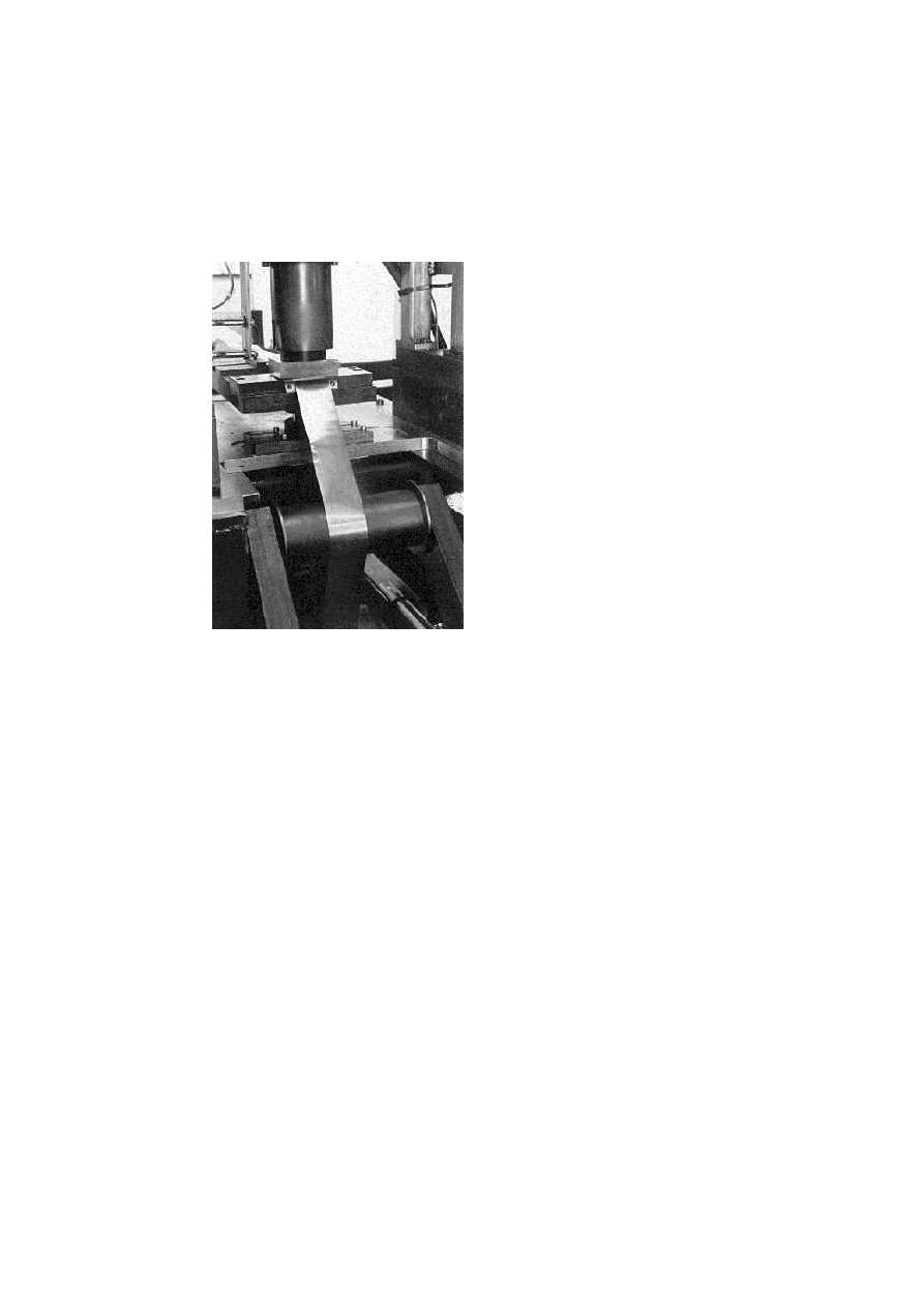
In order to reproduce the sliding of a sheet on a draw die radius with
the respect of the process conditions (geometry, pressure, sliding speed,
kinematics) as in a sheet metal forming process, we have improved our
pilot. This set up allows us to study wear on draw die radius. This device
uses sheet metal strip coil. The sheet metal strip is drawn through a blank
holder and a flat die, and guided by a return roll that allows to regulate the
exit angle between the sheet metal and the die radius (Fig. 1). During a test,
Mechanical Study of a Sheet Metal Forming Dies Wear
211
this angle is kept constant and the sliding distance is defined in two steps:
the first step is a sliding distance with blank holder action under pressure
and the second is without blank holder effect. This cycle is repeated several
times. For a test, we can define parameters such as the pressure of the blank
holder, sliding distance under pressure, free sliding distance, exit angle, the
speed of sheet metal strip and lubrication conditions.
Figure 1.
Pilot active part.
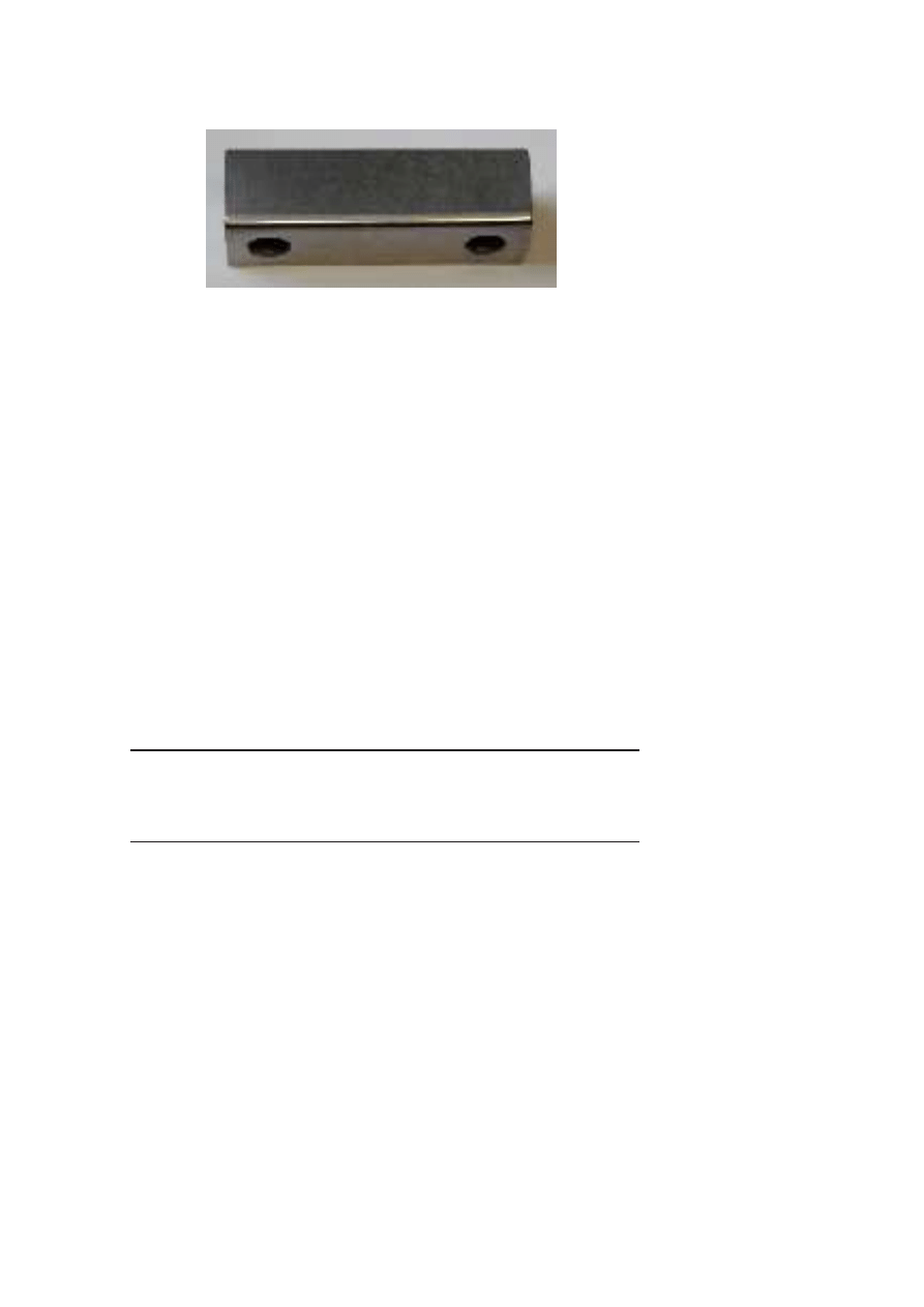
THE DRAW DIE RADIUS
The simple geometry of die radius specimen allows to reproduce only
one deformation mode: elongation mode. Two types of draw die radius
are studied in this paper. For the first, the radius is 2 mm and the material
is an X85MoCV05-05-04-02 steel (AISI-M2 or DIN1.3343), so called TA.
For the second, the radius is 6 mm and the material is an X160CrMoV12
(AISI-D2 or DIN 1.2379), so called TB. The materials are supplied from
industrial reference; we can notice that there is 12% of Chromium, for TB
212
6TH INTERNATIONAL TOOLING CONFERENCE
Figure 2.
Die radius specimen example 70 × 20 × 20 mm r = 2 mm.
and a carbon content, that leads to a high “wear resistance”. TA present
equally a good “wear resistance” combined with a good toughness. This is
the reason why they are used in sheet metal forming. The hardness level of
62HRc for TB, is obtained by austenitizing at 1080
◦
Cfor 30 min, quenching
and a double tempering (
2 × 2 hours) at 520
◦
C. The TA die is heat treated
in the same way and has a hardness between 60 to 65 HRc.
The other parts of tools such as blank holder, flat die are obtained in the
same conditions, The sheet metal strip has 1 mm thickness and 50 mm width.
We used a low carbon DC04 steel as sheet metal.
EXPERIMENTAL PARAMETERS
This experimental study involves 4 parameters (Table 1). In order to find
parameters which produce a significant wear, we have done some parameter
studies. We found the following parameters appropriate for the case of TA
and for DC04 sheet metal(Table 1).
Table 1.
Results of parameter studies
Pressure under blank holder [MPa]
4
Speed displacement [mm/s]
50
Sliding distance under pressure [mm]
100
Free sliding distance [mm]
50
Mechanical Study of a Sheet Metal Forming Dies Wear
213
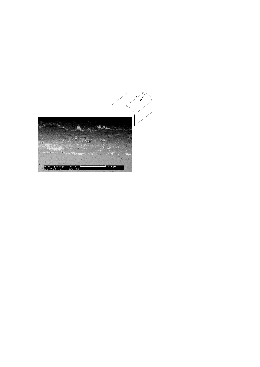
RESULTS
We present, only experimental results for the die radius TA, because it
exhibits more damage. After 3200 cycles, we can notice on the die radius,
two local worn zones. These are the white areas in Figs. 3 and 10. Local
wear zones are transfer zones (Fig. 4). This mechanism belongs to adhesive
wear mechanism. EDAX analysis allows us to confirm this point, since we
have found the chemical elements typical of the sheet metal on draw die
radius specimen.
A
B
A
B
sliding direction of sheet metal
Figure 3.
Die radius after wear test
FE MODEL TO STUDY THE REPARTITION OF PRES-
SURE ON THE DIE RADIUS.
The wear is produced through a local interaction between die and sheet
metal. One of these important tribological parameters is the pressure. Jensen
et al [4] have shown that the draw die radius is submitted to two local high
pressure areas. The first zone of local high pressure is the entry of radius and
the second is the exit of contact sheet metal/radius die. They used the Archard
model to study wear localization. More recently, Hortig et al [3] used the
same approach and they obtained the same results with an aluminium sheet.
214
6TH INTERNATIONAL TOOLING CONFERENCE
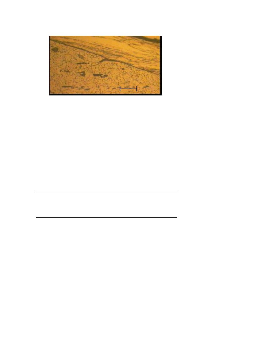
Die
Transfer
20 microns
Figure 4.
Cross-section observation of the die radius. Transfer width : 40 µm.
A first step to explain these two local transfer areas is to study the me-
chanical response of a draw die radius which is under a sheet metal strip
action.
FE MODEL
This model reproduces the experimental device features. We simulate
a sheet metal strip drawn through a blank holder under pressure. The dis-
placement of the sheet metal strip is guided in one fixed direction α (Fig. 5).
We have applied a displacement to the sheet metal end in direction α. The
value of geometry parameters are given in Table 2.
Table 2.
Geometry features.
Die radius (mm)
6
2
α, exit sliding angle (dg)
70
80
90
Sheet metal thickness (mm)
1
Distance between blank holder and die radius (mm)
0
30
The sheet metal strip has an elasto-plastic behaviour with an isotropic
hardening given by Hollomon model (Table 3); the draw die radius is as-
sumed elastic and the blank holder is assumed rigid.

Mechanical Study of a Sheet Metal Forming Dies Wear
215
R
displa emen
t
dire tion
of
the
sheet
metal
strip
blank
holder
d
die
radius
1
Figure 5.
Geometry of the model.
The interaction between all contact surfaces are assumed to obey a Coulomb
friction model, and we assumed a friction coefficient constant between each
contact surfaces (Tab 3).
This mechanical model was introduced in implicit FE code ABAQUS/Std
™.
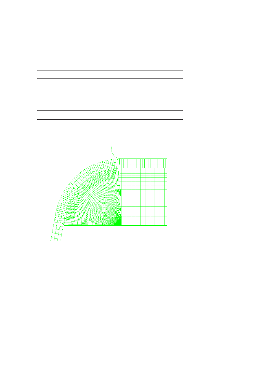
The Fig. 6 shows the 2D FE model for this strip test. The strip thickness is
meshed by 3 elements with linear interpolation displacement and reduced
integration points along a thickness. The draw die is meshed with linear
interpolation displacement elements and the thickness of elements increase
from 0.1 mm, near the sheet interface, to 3 mm in the die core.
Table 3 present FE model parameters.
FE MODEL RESULTS
In this part, we study the influence of α on the pressure profile. In this
case, we have choosen a radius of 6 mm and a distance d=0 mm. These
parameters allow to observe easier some remarkable pressure areas. In fact,
we observe two high pressure areas (Fig. 7). The first pressure peak is, for
this configuration, more important than the second peak, about 120 MPa
against 40 MPa. The second pressure zone spreads on a larger area than the
first zone.
The first pressure peak located at radius entry can be associated to the
bending of the sheet metal. The second located at 70
°, for this example,
from radius entry can be associated to the unbending. When the sheet metal
216
6TH INTERNATIONAL TOOLING CONFERENCE
Table 3.
FE model parameters.
Boundary conditions
Blank holder pressure [MPa]
4
Sliding distance [mm]
12
Material features
Young modulus (sheet metal) [GPa]
210
Young modulus (draw die radius) [GPa]
227
Poisson coef.
0.3
n
0.225
K [MPa]
530
Coulomb friction coef.
0.18
leaves the die radius contact, it is subjected to a unbending moment which
allows it to revert back to its straight state.
Figure 6.
Meshing of the geometry.
Mechanical Study of a Sheet Metal Forming Dies Wear
217
Figure 7.
Contact pressure profile on the die radius.
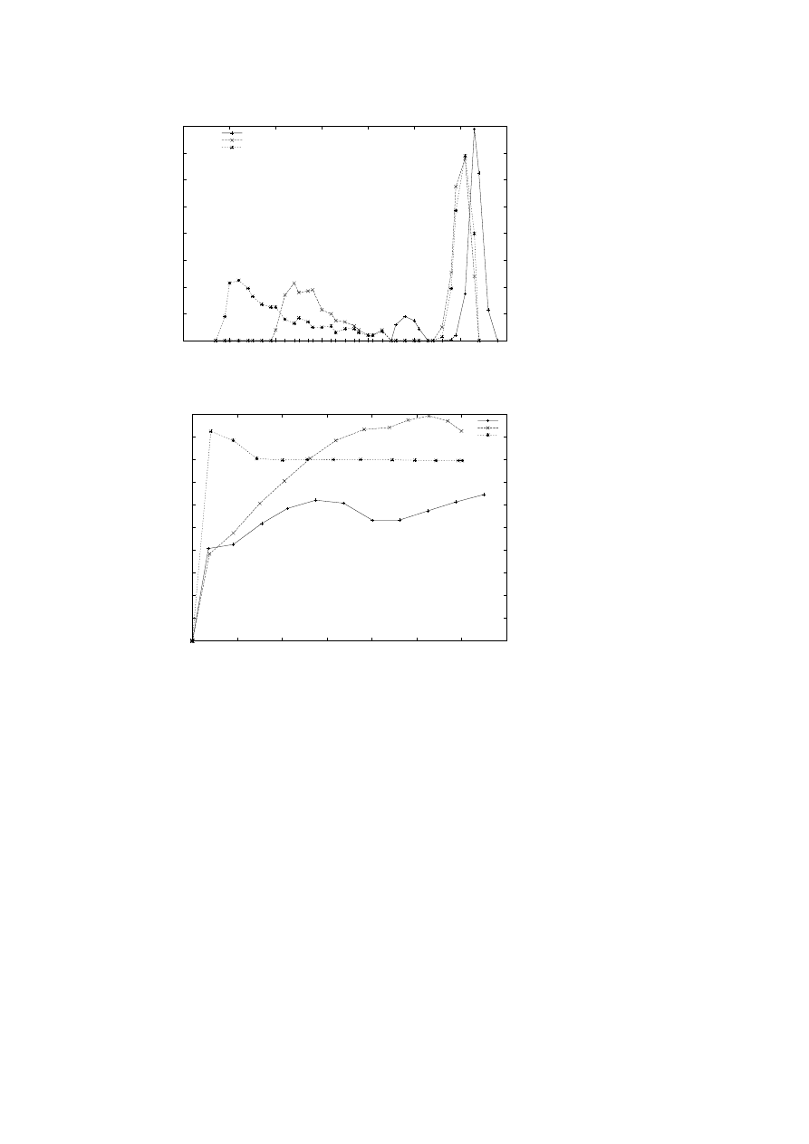
We can notice that the maximum pressure peak is reached for an angle
of 70
°, for the first peak pressure (Fig. 7). With variation of the exit sliding
angle from 70
° to 90°, we observed that the first peak decreases to a level of
140 MPa and the second peak increases (Fig. 8). This point shows us that in
a sheet metal forming process, during the punch displacement the pressure
maximum on die radius is not at the end (i.e at 90
°) but about 70°(for the same
geometry). These results have been pointed out also by the work of Mathey
et al [5]. On the other hand, the localization of the second high pressure
peak moves from entry to exit of die radius during the punch downwards
stroke. The contact surface increases with α and the second pressure area
spreads with α. But the beginning of this zone is independent of α.
The Fig. 8 shows that the first peak keeps at a constant position but the
second move toward the exit of radius die/sheet metal contact.
The strip tension force per unit of width is shown in Fig. 9 for each angle
α value. The evolutions through the displacement are different; they reach a
value between 40 and 50 N/mm. The maximum value is reached for α
= 80
°.
TRANSFER AREAS LINKED TO HIGH PRESSURE ZONES
We propose in this part to check if the high pressure zones are accountable
to transfer areas. In order to answer this question, we compared the average
experimental distance between two locals wear marks d
exp
with a distance
issue from FEM d
calc
.
The experimental set up chosen to treat this comparison is a die radius
specimen TA of r
= 2 mm and a distance between blank holder and die
218
6TH INTERNATIONAL TOOLING CONFERENCE
0
20
40
60
80
100
120
140
160
20
30
40
50
60
70
80
90
Pressure (MPa)
angular position on die radius
pressure repartition for each angle
angle70
angle80
angle90
Figure 8.
Influence of the exit strip angle on contact pressure profile on the die radius.
0
0.005
0.01
0.015
0.02
0.025
0.03
0.035
0.04
0.045
0.05
0
2
4
6
8
10
12
14
Traction strength of the sheet metal (KN)
displacement of sheet metal strip extremity (mm)
angle70
angle80
angle90
Figure 9.
Influence of the exit strip angle on tension force per unit width of the sheet metal
following α.
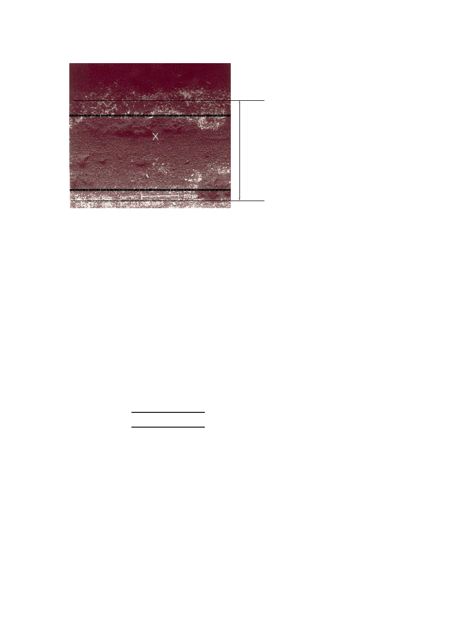
radius, d, of 30 mm. These parameters cause more damage on the die radius.
The d
exp
is measured from a MEB picture (Fig. 10).
Mechanical Study of a Sheet Metal Forming Dies Wear
219
d
exp
1
Figure 10.
BEM observations of TA die radius specimen.
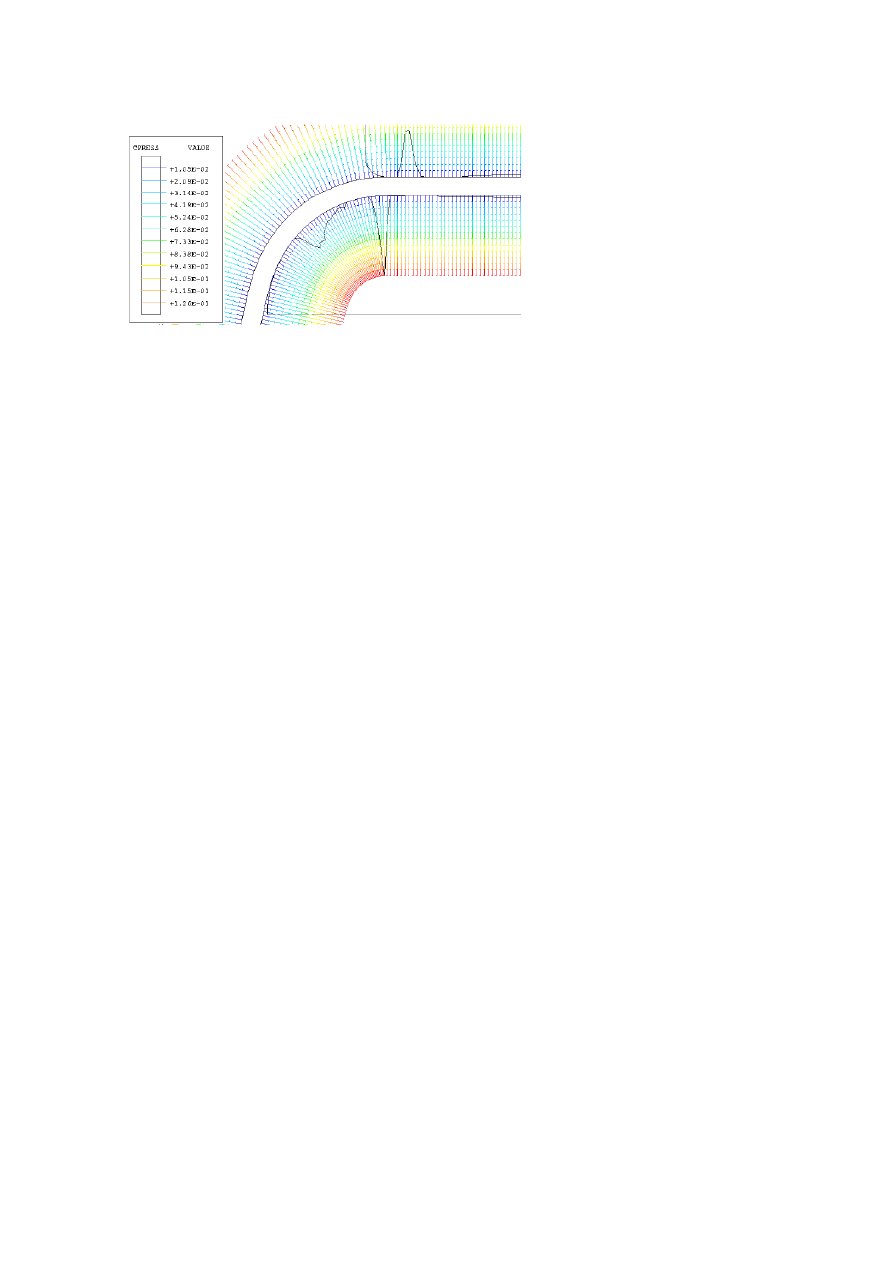
The result of the FE model with these parameters is presented in Fig. 11.
Peaks reach values of about 200 MPa. The knowledge of the angular position
of two high pressure peaks, from FEM, allows us to draw the expression of
d
calc
. d
calc
is the projected distance of the arc between both high pressure.
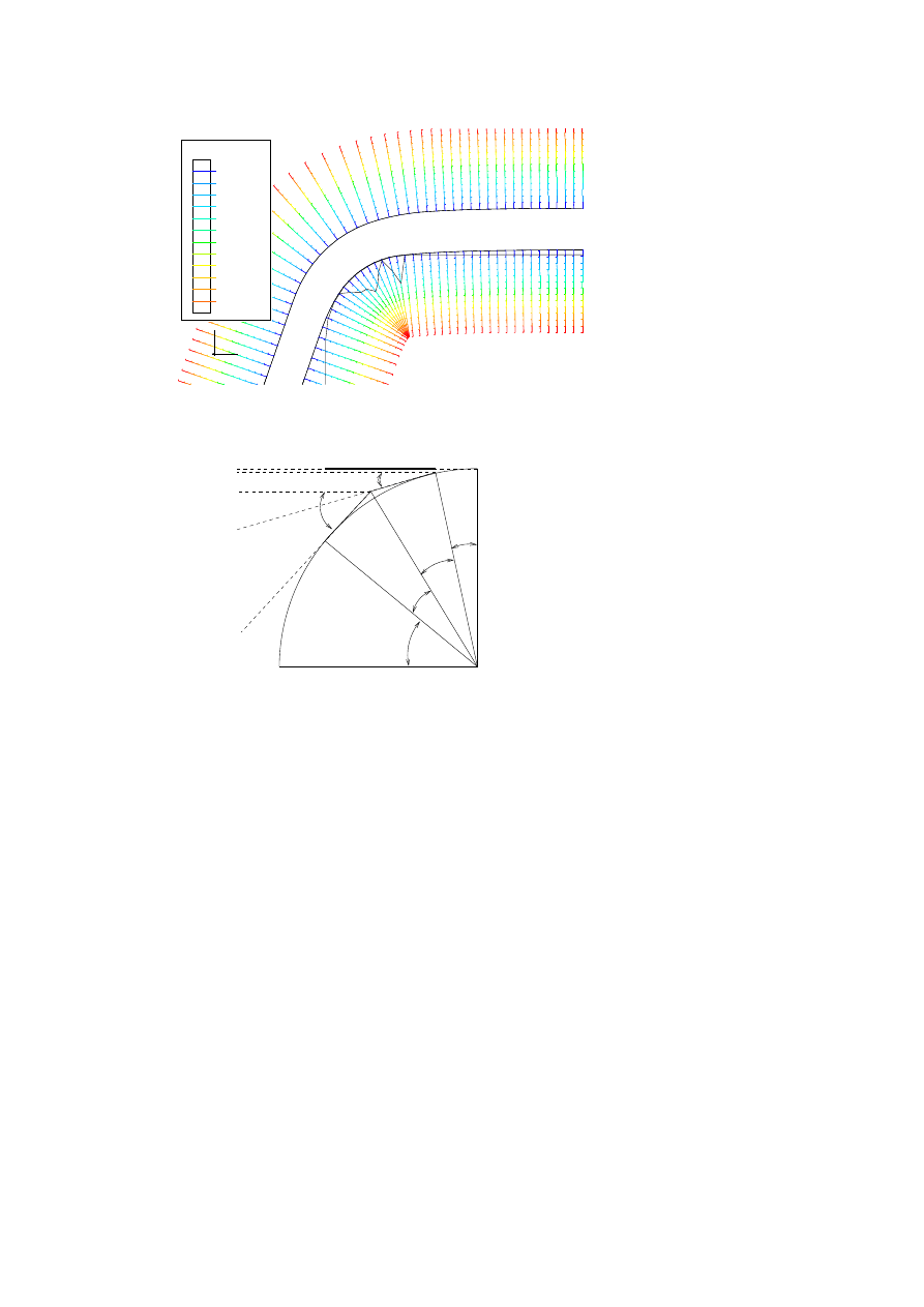
In Fig. 12, the points A and B represent positions of high pressure. They
are localized by there angular positions. Geometrical relation gives us the
expression of d
calc
.
Therefore the distance between peaks, d
calc
, is given by:
d
calc
= R tan(β)(cos(γ) + cos(α))
The result with FE model gives us the angular position (for r
= 2 mm)
(Table 4), we find d
calc
= 0.49 mm
Table 4.
Angulars position from FE model with a geometry TA.
2β
α
γ
26dg
37dg
11dg
220
6TH INTERNATIONAL TOOLING CONFERENCE
1
2
3
1
2
3
CPRESS
VALUE
+5.35E-02
+1.07E-01
+1.60E-01
+2.14E-01
+2.67E-01
+3.21E-01
+3.74E-01
+4.28E-01
+4.81E-01
+5.35E-01
+5.88E-01
+6.42E-01
DISPLACEMENT MAGNIFICATION FACTOR = 1.00
RESTART FILE = movtol30_ang70R2 STEP 3 INCREMENT 1273
TIME COMPLETED IN THIS STEP 100. TOTAL ACCUMULATED TIME 102.
ABAQUS VERSION: 5.8-1 DATE: 07-NOV-2001 TIME: 10:33:16
Figure 11.
Pressure on the die radius TA.
A
B
90-
a
d=pro
je tion
de
l'ar
de
er le
1
Figure 12.
Projection of the arc between both high pressure.
In the experiment, we have measured d
exp
=0.46 mm.
The incertitude
∆d
exp
is linked to measurement (0.005 mm) and location
of damage average zones, i.e delimitation of begining and the end of each
zone, this last one is more importante. Thus the transfer areas are linked
with high pressure zones as shown by the good agreement between d
calc
and
d
exp
.

Mechanical Study of a Sheet Metal Forming Dies Wear
221
CONCLUSION
A wear transfer mechanism is highlighted on die radius. This mechanism
is the result of local tribological conditions: one important parameter is the
local pressure. We found that this mechanism was localized in two specific
areas. These zones are the high pressure zones and they correspond to the
entry of the sheet metal strip on die radius and just before the exit contact
between die radius and sheet metal. A FE model allowed us to study the
mechanical response of a draw die radius under a sheet metal strip action.
These responses are different following the tension angular orientation of the
sheet metal strip. The most severe condition, ie the maximum high pressure,
is produced for an angle equal or less than 70
°. These numerical results are
linked with the transfer area observed in experimental tests.
ACKNOWLEDGMENTS
Financial support of the experimental equipment by French Ministry, Eu-
ropean comunity and CETIM for supplying sheet metal and tools contribut-
ing to D. ATTAF PhD program are gratefully acknowledged.
REFERENCES
[1] M. ERIKSEN, “The infuence of die geometriy on tool wear in deep drawing”, Wear,
207, (1997), pp 10-15.
[2] M. de ROOIJ “Tribological aspects of unlubricated deepdrawing processes”,PhD thesis
report, University of Twente, Enschede, (1998).
[3] D. HORTIG and D. SCHMOECKEL “Analysis of local loads on the draw die profile with
regard to wear using the FEM and experimental investigations”, Journal of Materials
ProcessingTechnology, 115, (2001), pp 153- 158.
[4] M.R. JENSEN, F.F. DAMBORG ,K.B. NIELSEN and J. DANCKERT”Applying the
finite-element method for determination of tool wear in conventional deep-drawing”,
Journal of Materials Processing Technology, 83, (1998), pp. 98-105.
[5] E. MATHEY, L. PENAZZI and C. MAGNY “Analyse de l’influence de la g´eom´etrie
sur les facteurs d’usure d’un outil d’emboutissage”, MECAMAT, (2002).
[6] A. PAILLEUX , “Outillage de frappe `a froid - Choix des mat´eriaux”, CETIM, France,
(1981).
[7] R.J.J.M. SNIEKERS Friction in deep drawing, PhD thesis report, TU Eindhoven, Dane-
mark, (1996).
[8] E. SCHEDIN , “Galling mechanisms in sheet forming operations”, Wear, 179, (1994),
pp 123-128.
Wyszukiwarka
Podobne podstrony:
64 919 934 New Trends in Thin Coatings for Sheet Metal Forming Tools
Ch07 sheet metal forming processes
The mechanism of storymaking A Grounded Theory study of the 6 Part Story Method (2006 The Arts in P
A Behavioral Genetic Study of the Overlap Between Personality and Parenting
Comparative Study of Blood Lead Levels in Uruguayan
Nukariya; Religion Of The Samurai Study Of Zen Philosophy And Discipline In China And Japan
A Study Of Series Resonant Dc Ac Inverter
52 737 754 Relationship Between Microstructure and Mechanical Properts of a 5%Cr Hot Works
32 425 436 Ifluence of Vacuum HT on Microstructure and Mechanical Properties of HSS
Mossbauer study of the retained austenitic phase in
pharr homer and the study of greek
03 Electrophysiology of myocardium Myocardial Mechanics Assessment of cardiac function PL
Hybrid Inorganic Organic Materials by Sol Gel Processing of Organofunctional Metal Alkoxides (2)
17 Benthic macroinvertebrates as indicators of water quality
moja 17, AGH IMIR Mechanika i budowa maszyn, II ROK, Metrologia Tyka Haduch, Metrologia, Metrologia,
więcej podobnych podstron