
Hydraulic Engineering into the 21st Century:
a Rediscovery of the Wheel ? (1) A Review
Hubert CHANSON, Reader, h.chanson@mailbox.uq.edu.au
Dept of Civil Engineering, The University of Queensland, Brisbane QLD 4072, Australia
Abstract
Hydraulics is the branch of civil engineering related to the science of water in motion,
and the interactions between the fluid and the surrounding environment. It is shown that
hydraulic engineers were at the forefront of science for centuries. The end of the 20th
century marked a change of perception in our society for hydraulic engineering. Is there a
need for further hydraulic engineering ? Yes, definitely. This is illustrated with an
example (culvert design) and complemented by a second paper (CHANSON 2003). Some
reflexions on the role of water engineering are presented. It is suggested that hydraulic
engineers and academics must be pro-active to develop further scholarship and quality
expertise as a part of a long-term strategy.
Keywords: hydraulic engineering, challenges, culvert, politics, teaching, education
1- Introduction
What is Hydraulic engineering ?
The beginnings of Civil engineering as a separate discipline may be linked to the
foundation of the 'Corps des Ponts et Chaussées' (Bridge and Highway Corps) in France
in 1716 and the establishment of the 'École Nationale des Ponts et Chaussées' (National
School of Bridges and Highways) in 1747. Among the directors were the famous
hydraulicians A. CHEZY (1717-1798) and G. de PRONY (1755-1839). Other famous
professors included B.F. de BELIDOR (1693-1761), J.B.C. BELANGER (1789-1874),
J.A.C. BRESSE (1822-1883), G.G. CORIOLIS (1792-1843) and L.M.H. NAVIER (1785-
1835). Hydraulics is the branch of civil engineering "that deals with practical applications
of liquid in motion" : e.g., the transmission of energy or the effects of flowing waters
(Merriam-Webster's Collegiate Dictionary). Hydraulic engineering deals with practical
applications of fluids, primarily liquids, in motion and it is related to fluid mechanics
which in large part provides its theoretical foundation.
In its broad sense, hydraulic engineering relates predominantly to the science of
water in motion, and the interactions between the flowing fluid (water) and the
surrounding environment. It encompasses a broad range of applications. Although some
involve man-made systems (e.g. aircrafts, submarines), many deal with the complexities
of Nature. Those latter applications include rainfall runoff, river engineering, sediment
transport, groundwater movement, lake, ocean and reservoir dynamics, waves, surface
Proc. 6th International Conference on Civil Engineering
Isfahan, Iran, May 5-7 2003
Keynote Lecture
flows, and the alteration of natural flows by man including pollution. Hydraulics is
clearly a field for people who care for Mother Nature and know how to apply the laws of
fluid mechanics for the benefits of our Society while preserving Nature (LIGGETT and
ETTEMA 2001). Hydraulic engineering deals with two- and three-phase flows, yet
includes also interactions with aquatic life (the fourth dimension !).
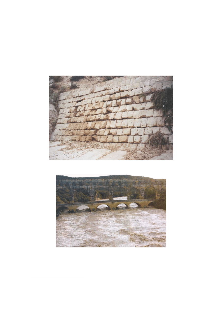
Fig. 1-1 : Ancient hydraulic works
(A) Nabataean dam on the Mamshit stream (also called Mampsis or Kunub) on 10 May 2001
(Courtesy of Dennis MURPHY) - Dam wall built around the end of 1st century BC - Downstream
slope of the dam wall
(B) Pont du Gard, Nîmes aqueduct, France during a flash flood in September 2002, looking
upstream (Photograph by Bernard WIS)
Past, present, and future
Hydraulic engineers were at the forefront of science for centuries (Fig. 1-1). For
example, although the origins of seepage water was long the subject of speculations (
1
),
the arts of tapping groundwater developed early in the Antiquity. The construction of
1
For example, "Meteorologica" by ARISTOTLE
qanats, which were hand-dug underground water collection tunnels, in Armenia and
Persia is considered as one great hydrologic achievement of the ancient world. Roman
aqueducts were magnificent waterworks and demonstrated the "savoir-faire" of Roman
engineers. The 132 km long Carthage aqueduct was considered one of the marvels of the
world by the Muslim poet EL KAIROUANI. Many aqueducts were used, repaired and
maintained for centuries and some are still used in parts (e.g. Carthage). A major
navigation canal system was the Grand canal fed by the Tianping diversion weir in
China. Completed in BC 219, the 3.9 m high 470 m long weir diverted the Xiang river
into the South and North canals, allowing navigation between Guangzhou (formerly
Canton), Shanghai and Beijing.
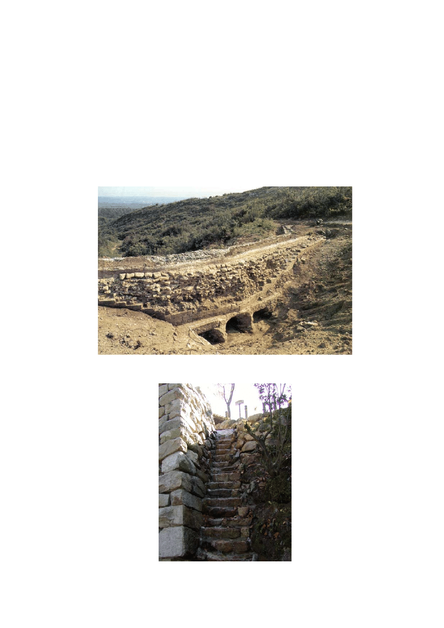
(C) Vallon No. 6 culvert (Nîmes aqueduct) during 1980s excavations (after FABRE et al. 1992) -
Note the inlet and the three cells beneath the aqueduct - The aqueduct flowed from left to right
(D) Storm waterway at Miya-jima (Japan) below Senjò-kaku wooden hall on 19 Nov. 2001 - The
steep stepped chute (
θ > 45º, h ~ 0.4 m) was built during the 12th century AD

Hydraulic engineers have had an important role to contribute although the technical
challenges are gigantic, often involving multiphase flows and interactions between fluids
and biological life. The extreme complexity of hydraulic engineering is closely linked
with the geometric scale of water systems, the broad range of relevant time scales, the
variability of river flows from zero during droughts to gigantic floods, the complexity of
basic fluid mechanics with governing equations characterised by non-linearity, natural
fluid instabilities, interactions between water, solid, air and biological life, and Man's
total dependence on water. The end of the 20th century marked a change of perception in
our society, especially in developed countries (ODGAARD 2001). Environmental issues,
sustainability and environmental management have become "fashionable" topics. What
do they mean ? Is there a need for further hydraulic engineering ? How can you manage
something without expert knowledge ? Will environmental managers save the planet from
floods and droughts ?
In the following paragraphs, an example of recent development in hydraulic
engineering is illustrated : i.e., the design of culverts. Further developments in hydraulic
engineering are developed in a second paper (CHANSON 2003). Later some reflexions
on the role of water engineering are presented.
2- A Typical Example: the Hydraulics of Culverts
2.1 Presentation
Culverts are among the most common hydraulic and civil engineering structures. A
culvert is a covered channel of relatively short length designed to pass water through an
embankment. Its purpose is to carry safely flood waters, drainage flows and natural
streams below the earthfill structure. Culverts have been used for more than 3000 years.
Although the world's oldest culvert is unknown, the Minoans and the Etruscans built
culverts in Crete and Northern Italy respectively (EVANS 1928, O'CONNOR 1993).
Later the Romans built numerous culverts beneath roads and aqueducts (BALLANCE
1951, O'CONNOR 1993, CHANSON 2002). The culvert construction was favoured for
small water crossings while bridge construction was preferred for longer crossings. Table
2-1 lists well-documented Roman culverts built beneath aqueducts. Figure 1-1C shows a
multicell culvert beneath the Nîmes aqueduct. This advanced design was capable of
discharging rainfall runoff in excess of 10 times the maximum aqueduct flow rate
(CHANSON 2002).
2.2 Hydraulic design of standard culverts
Modern designs of culverts do not differ much from Etruscan and Roman culverts
(e.g. Fig. 2-1). The primary design constraint is minimum construction costs, but
additional constraints might include maximum acceptable upstream flood level and scour
protection at outlet. The discharge capacity of the barrel is primarily related to the flow
pattern : free-surface barrel flow or drowned barrel. When free-surface flow takes place
in the barrel, the discharge is fixed by the entry conditions. Whereas with drowned
culverts, the discharge is determined by the culvert resistance. The design process for
standard culverts can be divided into two parts. First a system analysis must be carried
out to determine the objectives of the culvert, the design data, the constraints. In a second
stage, the barrel size is selected by a test-and-trial procedure, in which both inlet-control
and outlet-control calculations are performed. At the end the optimum size is the smallest
barrel size allowing for inlet
operation (e.g. CHANSON 1999, pp. 365-382).
Standard culverts are characterised by significant afflux at design flow conditions.
The afflux is the rise in upstream water level caused by the hydraulic structure. It is a
measure of upstream flooding. Numerous solutions were devised to reduce the afflux for

a given design flow rate by rounding the inlet edges, using throated entrances and warped
wing walls, introducing a bellmouth intake: e.g., California Division of Highways (1956),
NEILL (1962), Federal Highway Administration (1985), HAMILL (1999). These
solutions are expensive and often marginal.
Table 2-1 : Stormwater drainage systems (culvert & small bridges) beneath Roman aqueducts
Location Type
(a)
Barrel/throat characteristics
Remarks
(1) (2)
(3)
(4)
Small Bridges
Small bridge near
Vollem, Cologne
aqueduct
Arched
bridge
(a)
Single-rib segmental arch supported by
large stone block walls: 1.1-m wide,
1.1 maximum height. Cross-section
area : ~ 1 m2.
Meternich-Vollem, upstream end of
aqueduct.
Pont Bornègre,
Nîmes aqueduct
Arched
bridge
Three segmental arches (ashlar
masonry). Total span ~ 17 m.
Located 9 km u/s of Pont du Gard.
Catchment area ~ 0.7 km2. Max.
flood flow: 5 m3/s.
Pont-Amont at
Roc-Plan, Nîmes
aqueduct
Arched
bridge
3 arches (3.4 m high, 2.8 m wide, 5.4
m long) with 4 buttresses.
37.8 km upstream of Nîmes.
Pont de la Baume-
Sartanette, Nîmes
aqueduct
Arched
bridge
One arch (course rubble). Span : 4.08
m (2.23m after refurbishment)
Located 1.4 km d/s of Pont du
Gard. Catchment area: 0.3 km2.
Combe Joseph,
Nîmes aqueduct
Arched
bridge
One arch (rubble masonry). Span :
4.05 m.
Located 2,473 m d/s of Pont du
Gard. Catchment area: 0.14 km2.
Pont de la Combe
Pradier, Nîmes
aqu.
Arched
bridge
Single arch (original design). Aqueduct
invert elevation: 64.691 m NGF.
30.3 km upstream of Nîmes.
Culverts
Vallon No. 6
culvert, between
Combe de la
Sartanette and
Combe Joseph,
Nîmes aqueduct
Multi-
cell box
culvert
3 rectangular cells : 0.5
×0.65 m2, 0.8×
0.65 m2, 0.6
×0.65 m2. Cross-section
area : > 1.24 m2. Barrel construction :
large limestone blocks. Cutwater
design of dividing wall upstream end.
31.9 km upstream of Nîmes.
Downstream of Pont du Gard.
Catchment area: 0.028 km2. Max.
discharge capacity: 4.2 m3/s.
See Fig. 1-1C.
Pont-Aval at Roc-
Plan, Nîmes
aqueduct
Arched
culvert
(a)
3 biased cells (1.7 m high, 1.15 m
wide, 5.4 m long). Aqueduct invert
elevation: 66.381 m NGF.
38 km u/s of Nîmes. Barrel partly
cleared in Oct. 1988 during violent
storm which damaged Nîmes.
Culvert of the
Vallon de Coste-
Belle, Nîmes aqu.
Box
culvert
4 rectangular cells (5.5 m long). Total
opening width: 1.1 m. Construction :
Stone slabs.
36.9 km u/s of Nîmes, between
Pont Bornègre and Pont du Gard.
Culvert, Combe
Pradier, Nîmes
aqueduct (b)
Box
culvert
Single rectangular cell. Aqueduct
invert elevation: 64.691 m NGF.
Stage 2 after filling of the arch for
reinforcement. 30.3 km u/s of
Nîmes.
Culvert of Les
Escaunes, Nîmes
aqueduct
--
Aqueduct invert elevation: 64.1 m
NGF.
22 km u/s Nîmes. Between La
Perotte tunnel and Les Cantarelles
tunnel.
Culvert near Burg
Dalbenden,
Cologne aqueduct
Arched
culvert
1 cell (single rib segmental arch): 0.9-
m wide, 0.7-m maximum height.
Cross-section area : ~ 0.6 m2.
Kall-Urft, upstream end of
aqueduct.
Series of culverts,
Brévenne aqueduct
--
Locations : Chevinay across Le Plainet
stream; at Sourcieux; ...
Series of culverts,
Gier aqueduct
--
Locations : primarily in the upstream
section.
Notes: (a) : terminology after O'CONNOR (1993); (b) : after second refurbishment (Stage 2); (--):
no information. References: BURDY (1993), CHANSON (2002a), FABRE et al. (2000),
GREWE (1986).
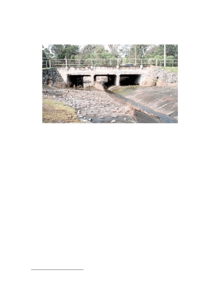
Fig. 2-1 : Standard culvert outlet below Algester Rd, Algester QLD (Australia) in Aug. 1999
2.3 Minimum Energy Loss culvert design
During the late 1950s and early 1960s, a new culvert design was developed in
Queensland (Australia) under the leadership of late Professor Gordon R. McKAY (1913-
1989): the Minimum Energy Loss (MEL) culvert (
2
). A MEL culvert is a structure
designed with the concept of minimum head loss and nearly-constant total head along the
waterway. The flow in the approach channel is contracted through a streamlined inlet into
the barrel where the channel width is minimum, and then is expanded in a streamlined
outlet before being finally released into the downstream natural channel. Both inlet and
outlet must be streamlined to avoid significant form losses and the flow is critical from
the inlet lip to the outlet lip. The barrel invert is usually lowered to increase the discharge
capacity (Fig. 2-2). The resulting MEL design is often capable to operate with zero afflux
at design flow. Professor C.J. APELT presented an authoritative review (APELT 1983)
and a well-documented audio-visual documentary (APELT 1994). The writer highlighted
the wide range of design options (CHANSON 2000,2001).
Since 1960, about 150 structures were built in Eastern Australia. While a number of
small-size culverts were built in Victoria, major structures were designed and built in
Queensland where torrential rains during the wet season place a heavy demand on
culverts and little head loss is permissible. The first MEL structure was the Redcliffe
storm waterway system (also called Humpybong Creek drainage outfall) completed in
1960. It consisted of a MEL weir acting as culvert drop inlet followed by a 137-m long
MEL culvert discharging into the Pacific Ocean. The weir was designed to prevent salt
intrusion in Humpybong Creek without afflux, while the culvert discharged flood water
underneath a shopping centre parking. The structure passed floods greater than the design
flow in several instances without flooding (McKAY 1970) and it is still used. The largest
MEL waterway is the Nudgee Road MEL waterway near the Brisbane airport with a
design discharge capacity of 800 m3/s and built between 1968 and 1970. The grass-lined
structure is still in use and passed successfully flood flows in excess of design flow.
2
Minimum Energy Loss culverts are also called Energy, Constant Energy, Minimum Energy,
Constant Specific Energy culverts ... (e.g. APELT 1983).
Several MEL culverts were built in southern Brisbane during the construction of the
South-East Freeway in 1970-1971. The design discharge capacities ranged from 200 to
250 m3/s. The culverts operate typically several days per year (Fig. 2-2B). McKAY
(1971) indicated further MEL culverts built in Northern Territory near Alice Springs in
1970. COTTMAN and McKAY (1990) described the Newington bridge MEL water
completed in 1975 (Qdes = 142 m3/s). In 1975 and 1988, the structure passed 122 and
150 m3/s respectively without any damage.
MEL culverts received some strong interests in Canada, USA and UK : e.g., LOWE
(1970), LOVELESS (1984), Federal Highway Administration (1985, p. 114).
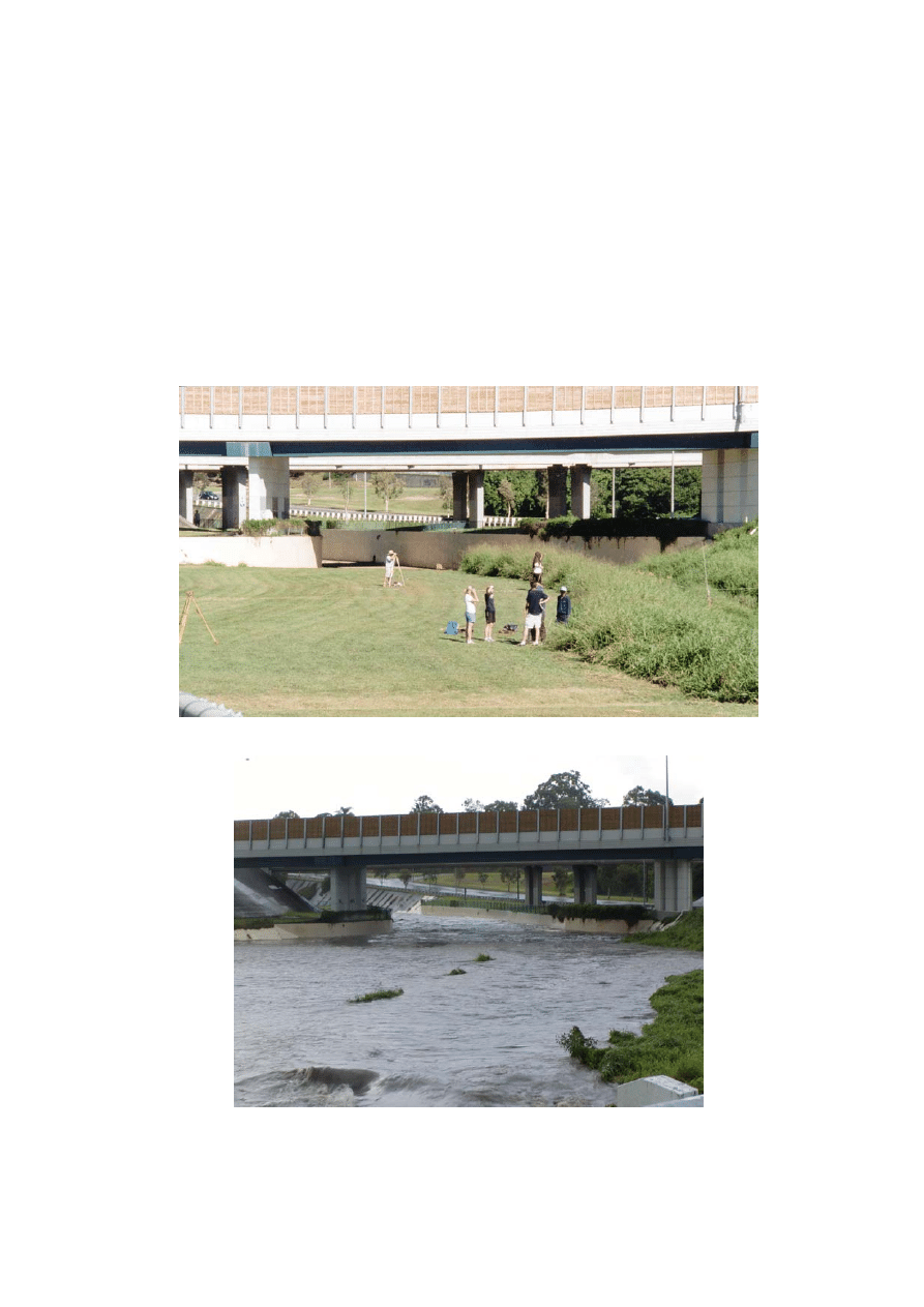
Fig. 2-2 : Minimum Energy Loss waterway in Brisbane
(Qdes = 220m3/s, Bmax = 33m, Bmin = 11m)
(A) Waterway outlet looking upstream on 13 May 2002 - Note the busway and motorway bridges
above the channel and students surveying the waterway
(B) MEL waterway in operation on 31 Dec. 2001 for about 80 m3/s looking upstream
Prototype experience
Several structures were observed operating at design flows and for floods larger than
design. Inspections during and after flood events demonstrated a sound operation

associated with little maintenance. While McKAY (1971) gave general MEL culvert
guidelines, Professor Colin APELT stressed that a successful design must follow closely
two basic design concepts: streamlining of the flow and near-critical flow conditions
APELT (1983). Flow separation must be avoided at all cost. In one structure, separation
was observed in the inlet associated with flow recirculation in the barrel (Cornwall St,
Brisbane). MEL culverts are usually designed for Fr = 0.6 to 0.8 and supercritical flow
conditions must be avoided. This is particularly important in the outlet where separation
must be avoided as well.
The successful operation of large MEL culverts for over 40 years has highlighted
further practical considerations. MEL culverts must be equipped with adequate drainage
to prevent water ponding in the barrel invert. Drainage channels must be preferred to
drainage pipes. For example, the MEL waterway shown in Figure 2-2 is equipped with a
well-designed drainage system. One issue is the loss of expertise in MEL culvert design.
In Brisbane, two culvert structures were adversely affected by the construction of a new
busway 25 years later (
3
). As a result, one major arterial will be overtopped during a
design flood (Marshall Rd, Brisbane).
3. Challenges ahead : Teaching hydraulic engineering
Water plays a major role in human perception of the environment because it is an
indispensable element. The technical challenges are formidable : sustained research and
teaching efforts are essential. Scientific progresses have been hampered by a lack of
concerted support from a generation of "environmental planners" and politicians. During
the last three decades, universities in developed countries have rationalised their
engineering curricula. This has been associated with the development of computer-based
courses, project-based subjects, and flexible delivery material, often at the expenses of
lecture quality, practical studies and field works. The education of hydraulic engineers is
a major challenge. Basic fluid mechanics is introduced in engineering and applied
mathematics degrees. Some hydraulics subjects might be offered in postgraduate courses,
but hydraulic engineering involves the interactions between water, soil, air and aquatic
life. Such topics are not taught in undergraduate nor postgraduate curricula in most
universities. The writer has lectured basic hydraulics, sediment processes, hydraulic
design and air-water flows at both undergraduate and postgraduate levels since 1991
(CHANSON 1999,2001). He believes that many researchers, professionals and
government administrators do not fully appreciate the complexity of hydraulic
engineering nor the needs for further education of quality.
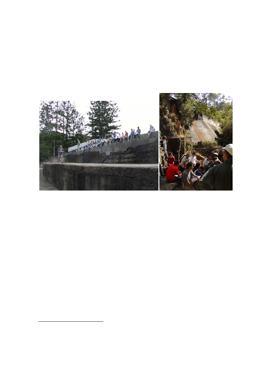
Figures 2-2C and 3-1 illustrate hands-on teaching of hydraulics. Figure 3-1A shows
Open Channel Flow students (3rd Year) inspecting the Gold Creek dam spillway. Key
features include a 55-m wide, 60-m long broad crest, a stepped chute and the absence of
downstream stilling basin. Figure 3-1B shows Hydraulic Design students (4th Year) in
front of the fully-silted Korrumbyn Creek dam. The dam and reservoir were accessed
after a half-hour bushwalk guided by the rangers in the dense sub-tropical rainforest of
Mt Warning National Park (NSW). Figure 2-2C presents Civil Design students (4th Year)
surveying a MEL culvert. Altogether 8 culverts and flood plains were surveyed and
analysed, and results were presented in a series of reports and oral presentations assessed
by student peers and lecturers. Overall, anonymous student feedback demonstrated that
students considered field works as an essential component of the hydraulic engineering
courses and an important aspect of the civil engineering curriculum. Field works were
3
This new busway is visible in Figure 2-2, above the MEL waterway outlet, but this structure was
not affected.
well-suited for group works, allowing students to gain better in-depth understanding of
professional teamwork and designs. Although the students believed that field studies did
not replace traditional lectures, most felt that the field experience helped them to think
more critically in hydraulic engineering. Anonymous results indicated further that field
studies were not self-learning. Students needed expert guidance and knowledge to
comprehend all aspects of a prototype design.
Fig. 3-1 : Undergraduate student field works at the University of Queensland
(Left) Open channel flow class (84 students) in Gold Creek dam stepped spillway
(Right) Hydraulic design class (24 students) in front of the fully-silted Korrumbyn Creek dam
4. Political role(s) of water systems
The sustainable development of Earth water systems is the key of long-term peace
and stability. The control of water systems is closely linked with political stability. The
21st century is facing high risks of armed conflicts centred around water systems, and
freshwater system issues will be the focal point of future armed conflicts. For example,
the Tigris and Euphrates river catchments with potential conflicts between Turkey, Iraq
and Syria. This situation is not new but the risks are far greater in the 21st century.
Armed conflicts around freshwater systems have been plenty. In the Bible, a wind-
setup effect allowed Moses and the Hebrews to cross shallow water lakes and marshes
during their exodus. Droughts were artificially introduced : e.g., during the siege of the
ancient city of Khara Khoto ('Black City') in AD 1372, the Chinese army diverted the
Ezen river (
4
) supplying water to the city (
5
). Man-made flooding (
6
) of an army or a city
was carried out by the Assyrians (Babylon, Iraq BC 689), the Spartans (Mantinea, Greece
BC 385-84), the Chinese (Huai river, AD 514-15), the Russian army (Dnieprostroy dam,
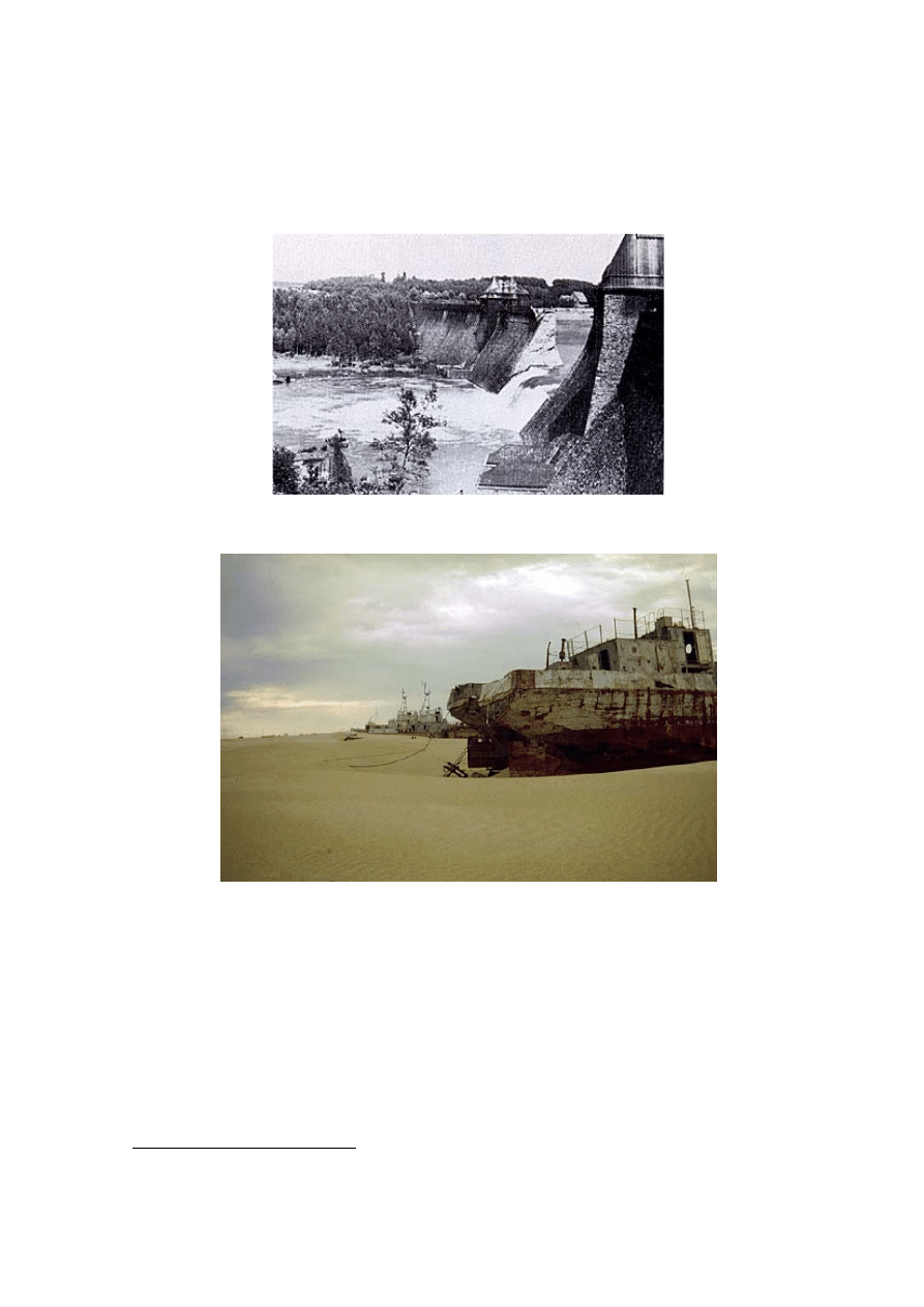
1941). A related case was the air raid on the Möhne dam conducted by the British, in
1943, during the dam buster campaign (Fig. 4-1). Dyke destruction and associated
flooding played also a role in several wars. For example, the war between the cities of
Lagash and Umma (Assyria) around BC 2,500 was fought for the control of irrigation
systems and dykes; the Dutch broke dykes near Amsterdam to stop the French army in
4
also called Hei He river ('Black River') by the Chinese.
5
Located in the Gobi desert, Khara Khoto was ruled by the Mongol king Khara Bator (WEBSTER
2002).
6
by building an upstream dam and destroying it.
1672; in 1938, the Chinese army destroyed dykes along the Huang Ho River (Yellow
River) to slow down the Japanese army.
Fig. 4-1 : Möhne dam shortly after the R.A.F. raid on 16-17 May 1943 - Almost 1,300 people
died in the floods following the dam buster campaign, mostly inmates of a Prisoner of War
(POW) camp just below the dam.
Fig. 4-2 : Former military ships on 12 September 1996 at Vozrozhdenie Island, Big Aral Sea
(Courtesy of TETHYS-JRAK expedition, photograph by Roman Jashenko)
Recently some attention was focused on river management of large water systems :
e.g., the Mekong river and the discord between China, Thailand, Laos, Cambodia and
Vietnam. However lesser known water conflicts are likely to generate armed conflicts.
The scope of the relevant issues is broad and complex, and includes water pollution,
water supply, flooding, drought. An example is the disaster of the Aral Sea (e.g.
WALTHAM and SHOLJI 2001). Since 1987, the Aral Sea is divided by a permanently-
dry isthmus between the northern small Aral Sea and the southern big Aral Sea. Figure 4-
2 illustrates grounded freighters as the result of the sea shrinkage (
7
).
7
The Vozrozhdenie Island, in the west part of the big Aral Sea, is a huge dump of chemical
weapons from the former Soviet Union. Today it is almost connected to the mainland.

5. Conclusion
Water plays a major role on our Planet because it is an indispensable element. The
technical challenges associated with water engineering are formidable. Sustained teaching
and research efforts are essential. Hydraulic engineers were at the forefront of science for
centuries. Famous examples include the qanats and the Grand canal in China. The end of
the 20th century marked however a change perception of hydraulic engineering with a
shift in focus toward environmental issues, sustainability and management. Such trends,
led by government institutions, industries and university administrations, have placed
more focus on political issues at the expenses of quality expertise and engineering
innovation.
Further advances in hydraulic engineering are a basic necessity to provide Humanity
with water during this 21st century. The writer has shown innovative developments in
hydraulic engineering of basic structures (culverts) which must be associated with active
research and dynamic teaching. The writer believes that hydraulic engineers and
academics must be pro-active and dynamic to develop further scholarship and quality
expertise as a part of a long-term strategy. It is the writer's belief that the development of
our planet cannot succeed without further Research and Higher Education initiatives
(incl. funding) in Hydraulic Engineering.
6. Acknowledgments
The writer thanks Professor Colin APELT for his helpful comments.
7. References
APELT, C.J. (1983). "Hydraulics of Minimum Energy Culverts and Bridge Waterways."
Australian Civil Engrg Trans., I.E.Aust., Vol. CE25, No. 2, pp. 89-95.
APELT, C.J. (1994). "The Minimum Energy Loss Culvert." Videocassette VHS colour, Dept. of
Civil Eng., University of Queensland, Australia, 18 minutes.
BALLANCE, M.H. (1951). "The Roman Bridges of the Via Flaminia." Papers of the British
School at Rome, Vol. 19, pp. 78-117 & plates xiv to xix.
BURDY, J. (1993). "Préinventaire des Monuments et Richesses Artistiques. III L'Aqueduc
Romain de la Brévenne." Bosc Frères Publ., Lyon, France, 230 pages & 1 Map (in French).
California Division of Highways (1956). "California culvert practice : reprint of a series of
technical abstracts from California highways and public works." Division of Highways, Dept.
of Public Works, State of California, 2nd edition, 119 pages & 1 map.
CHANSON, H. (1999). "The Hydraulics of Open Channel Flows : An Introduction." Butterworth-
Heinemann, Oxford, UK, 512 pages.
CHANSON, H. (2000). "Introducing Originality and Innovation in Engineering Teaching: the
Hydraulic Design of Culverts." European Journal of Engineering Education, Vol. 25, No. 4,
pp. 377-391.
CHANSON, H. (2001). "Teaching Hydraulic Design in an Australian Undergraduate Civil
Engineering Curriculum." Jl of Hyd. Engrg., ASCE, Vol. 127, No. 12, pp. 1002-1008.
CHANSON, H. (2002). "Hydraulics of a Large Culvert beneath the Roman Aqueduct of Nîmes."
Jl of Irrigation and Drainage Engrg., ASCE, Vol. 128, No. 5, pp. 326-330.
CHANSON, H. (2003). "Hydraulic Engineering into the 21st Century: the Rediscovery of the
Wheel ? (2) New Challenges." Proc. 6th Intl Conf. on Civil Eng., Isfahan, Iran, May 5-7,
Keynote lecture, 2nd part, 12 pages.
COTTMAN, N.H., and McKAY, G.R. (1990). "Bridges and Culverts Reduced in Size and Cost
by Use of Critical Flow Conditions." Proc. Instn. Civ. Engrs., London, Part 1, Vol. 88, pp.
421-437. Discussion : 1992, Vol. 90, pp. 643-645.
EVANS, A.H. (1928). "The Palace of Minos : a comparative account of the successive stages of
the early Cretan civilization as illustrated by the discoveries at Knossos." Macmillan, London,
UK, Vol. II, Part 1, 390 pages & 19 plates.

FABRE, G., FICHES, J.L., LEVEAU, P., and PAILLET, J.L. (1992). "The Pont du Gard. Water
and the Roman Town." Presses du CNRS, Caisse Nationale des Monuments Historiques et des
Sites, Collection Patrimoine au Présent, Paris, France, 127 pages.
FABRE, G., FICHES, J.L., and PAILLET, J.L. (2000). "L'Aqueduc de Nîmes et le Pont du Gard.
Archéologie, Géosystème, Histoire." CNRS Editions, CRA Monographies Hors Série, Paris,
France, 483 pages & 16 plates (in French).
Federal Highway Administration (1985). "Hydraulic design of Highway Culverts." Hydraulic
Design Series No. 5, Report No. FHWA-IP-85-15, US Federal Highway Admin., 253 pages.
GREWE, K. (1986). "Atlas der Römischen Wasserleitungen nach Köln." ('Atlas of the Roman
Hydraulic Works near Köln.') Rheinland Verlag, Köln, Germany, 289 pages (in German).
HAMILL, L. (1999). "Bridge Hydraulics." E&FN Spon, London, UK, 367 pages.
LIGGETT, J.A., and ETTEMA, R. (2001). "Civil-engineering education: Alternative paths." Jl of
Hyd. Engrg., ASCE, Vol. 127, No. 12, pp. 1041-1051.
LOVELESS, J.H. (1984). "A Comparison of the Performance of Standard and Novel Culvert
Designs including the Effects of Sedimentation." Proc. 1st Intl Conf. Hydraulic Design in
Water Resources Engineering: Channels and Channel Control Structures, K.V.H. SMITH
Ed., Southampton, UK, Springer Verlag Publ., Vol. 1, pp. 183-193.
LOWE, S.A. (1970). "Comparison of Energy Culverts to Standard Three Cell Box Culverts."
Masters thesis, University of Manitoba, Canada.
McKAY, G.R. (1970). "Pavement Drainage." Proc. 5th Aust. Road Res. Board Conf., Vol. 5, Part
4, pp. 305-326.
McKAY, G.R. (1971). "Design of Minimum Energy Culverts." Research Report, Dept of Civil
Eng., Univ. of Queensland, Brisbane, Australia, 29 pages & 7 plates.
NEILL, C.R. (1962). "Hydraulic Tests on Pipe Culverts." Alberta Highway Research Report 62.1,
Research Council of Alberta, Edmonton, 52 pages.
O'CONNOR, C. (1993). "Roman Bridges." Cambridge University Press, UK, 235 pages.
ODGAARD, A.J. (2001). "Trends and Current Developments in Hydraulic Engineering."
Workshop on Integrated Water Resources Management, National Chiao Tung University,
Hsinchu, Taiwan, October 15-16, Keynote Lecture.
WALTHAM, T., and SHOLJI, I. (2001). "The Demise of the Aral Sea - An Environmental
Disaster." Geology Today, Vol. 17, No. 6, pp. 218-224.
WEBSTER, D. (2002)."China's Unknown Gobu: Alashan." National Geographic, Vol. 201, No.
1, p. 48.
Wyszukiwarka
Podobne podstrony:
Business Coffee Caffe Latte Art in the 21st Century
Gray The 21st Century Security Environment and the Future of War Parameters
Randall Doyle The Roots of War in the 21st Century, Geography, Hegemony, and Politics in Asia Pacif
0415149282 Routledge The Future of Philosophy Towards the 21st Century Mar 1998
Hbr Michael Porter The Semiconductor Industry In The 21St Century
3E D&D Adventure 07 Into the Frozen Waste
J Slowacki Into the midst of riotous squabblers
International relations theory for 21st century
Out of the Armchair and into the Field
Cthulhu Rising Life in the 23rd Century
KasparovChess PDF Articles, Sergey Shipov Traditions of the Nineteenth Century Still Are Alive and
12 Put the verb into the correct form
A Bite Into the History of the Autopsy
07 Into the Shadows
70 1003 1019 Influence of Surface Engineering on the Performance of Tool Steels for Die Casting
Intraindividual stability in the organization and patterning of behavior Incorporating psychological
An insight into the New Austrian Tunnelling Method (NATM)
więcej podobnych podstron