4092-00X
7000 Color Jetprinter™
7200, 7200V Color Jetprinter
Lexmark and Lexmark with diamond
design are trademarks of Lexmark
International, Inc., registered in the
United States and/or other countries.
• Index

First Edition (November 1997)
The following paragraph does not apply to any country where such
provisions are inconsistent with local law: LEXMARK
INTERNATIONAL, INC. PROVIDES THIS PUBLICATION “AS IS”
WITHOUT WARRANTY OF ANY KIND, EITHER EXPRESS OR IMPLIED,
INCLUDING, BUT NOT LIMITED TO, THE IMPLIED WARRANTIES OF
MERCHANTABILITY OR FITNESS FOR A PARTICULAR PURPOSE.
Some states do not allow disclaimer of express or implied warranties in
certain transactions, therefore, this statement may not apply to you.
This publication could include technical inaccuracies or typographical
errors. Changes are periodically made to the information herein; these
changes will be incorporated in later editions. Improvements or changes in
the products or the programs described may be made at any time.
Comments may be addressed to Lexmark International, Inc., Department
D22A/035-3, 740 New Circle Road, Lexington, Kentucky 40550, U.S.A.
Lexmark may use or distribute any of the information you supply in any way
it believes appropriate without incurring any obligation to you.If your printer
has broken or missing parts, or if you are missing publications, call 1-800-
4LEXBMP. In other countries, contact your point of purchase. You can
obtain additional copies of publications related to this product by calling 1-
800-553-9727.
Lexmark is a trademark of Lexmark International, Inc., registered in the
United States and/or other countries. Color Jetprinter is a trademark of
Lexmark International, Inc. Other trademarks are the property of their
respective owners.
© Copyright Lexmark International, Inc. 1997. All rights reserved.
UNITED STATES GOVERNMENT RESTRICTED RIGHTS
This software and documentation are provided with RESTRICTED
RIGHTS. Use, duplication or disclosure by the Government is subject to
restrictions as set forth in subparagraph (c)(1)(ii) of the Rights in Technical
Data and Computer Software clause at DFARS 252.227-7013 and in
applicable FAR provisions: Lexmark International, Inc., Lexington, KY
40550.
4092

iv
4092
Contents
1
Preface . . . . . . . . . . . . . . . . . . . . . . . . . . . . . . . . . . . . . . . . . . . . . .vii
General Information . . . . . . . . . . . . . . . . . . . . . . . . . . . . . . . . . . 1-1
Operator Panel. . . . . . . . . . . . . . . . . . . . . . . . . . . . . . . . . . . . 1-1
Resolution and Print Speed . . . . . . . . . . . . . . . . . . . . . . . . . . 1-1
Power Consumption. . . . . . . . . . . . . . . . . . . . . . . . . . . . . . . . 1-2
Maintenance Approach . . . . . . . . . . . . . . . . . . . . . . . . . . . . . 1-2
Diagnostic Information . . . . . . . . . . . . . . . . . . . . . . . . . . . . . . . . 2-1
Start . . . . . . . . . . . . . . . . . . . . . . . . . . . . . . . . . . . . . . . . . . . 2-1
Error Indicator Table . . . . . . . . . . . . . . . . . . . . . . . . . . . . 2-2
Power-On Self Test (POST) Sequence . . . . . . . . . . . . . . 2-2
POST Symptom Table. . . . . . . . . . . . . . . . . . . . . . . . . . . 2-3
Symptom Tables . . . . . . . . . . . . . . . . . . . . . . . . . . . . . . . 2-4
Service Checks . . . . . . . . . . . . . . . . . . . . . . . . . . . . . . . . . . . 2-6
Envelope Feed Service Check . . . . . . . . . . . . . . . . . . . . 2-6
First Print Line Service Check . . . . . . . . . . . . . . . . . . . . . 2-6
Maintenance Station Service Check . . . . . . . . . . . . . . . . 2-7
Paper Feed Service Check . . . . . . . . . . . . . . . . . . . . . . . 2-8
Paper Path Service Check . . . . . . . . . . . . . . . . . . . . . . 2-10
Parallel Port Service Check. . . . . . . . . . . . . . . . . . . . . . 2-11
Power Service Check . . . . . . . . . . . . . . . . . . . . . . . . . . 2-11
Print Quality Service Check. . . . . . . . . . . . . . . . . . . . . . 2-12
Transport Service Check . . . . . . . . . . . . . . . . . . . . . . . . 2-15
Diagnostic Aids . . . . . . . . . . . . . . . . . . . . . . . . . . . . . . . . . . . . . . 3-1
Repair Information . . . . . . . . . . . . . . . . . . . . . . . . . . . . . . . . . . . . 4-1

v
4092
Connector Locations . . . . . . . . . . . . . . . . . . . . . . . . . . . . . . . . . .5-1
Preventive Maintenance . . . . . . . . . . . . . . . . . . . . . . . . . . . . . . .6-1
Lubrication Specifications . . . . . . . . . . . . . . . . . . . . . . . . . . . . 6-1
Parts Catalog . . . . . . . . . . . . . . . . . . . . . . . . . . . . . . . . . . . . . . . .7-1
How To Use This Parts Catalog . . . . . . . . . . . . . . . . . . . . . . . 7-1
Assembly 1: Covers . . . . . . . . . . . . . . . . . . . . . . . . . . . . . . . . 7-2
Assembly 2: Frames . . . . . . . . . . . . . . . . . . . . . . . . . . . . . . . . 7-4
Assembly 3: Paper Feed . . . . . . . . . . . . . . . . . . . . . . . . . . . . 7-6
Assembly 4: Electronics . . . . . . . . . . . . . . . . . . . . . . . . . . . . . 7-8
Assembly 5: Carrier . . . . . . . . . . . . . . . . . . . . . . . . . . . . . . . 7-12
Assembly 6: Carrier Transport . . . . . . . . . . . . . . . . . . . . . . . 7-14

vi
4092
Assembly 7: Sheet Feeder. . . . . . . . . . . . . . . . . . . . . . . . . . 7-16
Assembly 8: Maintenance Station . . . . . . . . . . . . . . . . . . . . 7-18

4092
Preface
vii
Preface
2
This manual is divided into the following chapters:
1. General Information contains a general description of the
printer and the maintenance approach used to repair it. Special
tools and test equipment are listed in this chapter, as well as
general environmental and safety instructions.
2. Diagnostic Information contains error indicator table, symptom
table, and service checks used to isolate failing field replaceable
units (FRUs).
3. Diagnostic Aids contains tests and checks used to locate or
repeat symptoms of printer problems.
4. Repair Information provides instructions for making printer
adjustments and removing and installing FRUs.
5. Connector Locations uses illustrations to identify the connector
locations and test points on the printer.
6. Preventive Maintenance contains the lubrication specifications
and recommendations to prevent problems.
7. Parts Catalog contains illustrations and part numbers for indi-
vidual FRUs.
Safety Information
•
This product is designed, tested and approved to meet strict
global safety standards with the use of specific Lexmark
components. The safety features of some parts may not always
be obvious. Lexmark is not responsible for the use of other
replacement parts.
•
The maintenance information for this product has been prepared
for use by a professional service person and is not intended to
be used by others.
•
There may be an increased risk of electric shock and personal
injury during disassembly and servicing of this product.
Professional service personnel should understand this and take
necessary precautions.

4092
viii
Consignes de Sécurité
•
Ce produit a été conçu, testé et approuvé pour respecter les
normes strictes de sécurité globale lors de l'utilisation de
composants Lexmark spécifiques. Les caractéristiques de
sécurité de certains éléments ne sont pas toujours évidentes.
Lexmark ne peut être tenu responsable de l'utilisation d'autres
pièces de rechange.
•
Les consignes d'entretien et de réparation de ce produit
s'adressent uniquement à un personnel de maintenance
qualifié.
•
Le démontage et l'entretien de ce produit pouvant présenter
certains risques électriques, le personnel d'entretien qualifié
devra prendre toutes les précautions nécessaires.
Norme di sicurezza
•
Il prodotto è stato progettato, testato e approvato in conformità a
severi standard di sicurezza e per l’utilizzo con componenti
Lexmark specifici. Le caratteristiche di sicurezza di alcune parti
non sempre sono di immediata comprensione. Lexmark non è
responsabile per l’utilizzo di parti di ricambio di altri produttori.
•
Le informazioni riguardanti la manutenzione di questo prodotto
sono indirizzate soltanto al personale di assistenza autorizzato.
•
Durante lo smontaggio e la manutenzione di questo prodotto, il
rischio di subire scosse elettriche e danni alla persona è più
elevato. Il personale di assistenza autorizzato, deve, quindi,
adottare le precauzioni necessarie.

4092
Preface
ix
Sicherheitshinweise
•
Dieses Produkt und die zugehörigen Komponenten wurden
entworfen und getestet, um beim Einsatz die weltweit gültigen
Sicherheitsanforderungen zu erfüllen. Die sicherheitsrelevanten
Funktionen der Bauteile und Optionen sind nicht immer
offensichtlich. Sofern Teile eingesetzt werden, die nicht von
Lexmark sind, wird von Lexmark keinerlei Verantwortung oder
Haftung für dieses Produkt übernommen.
•
Die Wartungsinformationen für dieses Produkt sind
ausschließlich für die Verwendung durch einen
Wartungsfachmann bestimmt.
•
Während des Auseinandernehmens und der Wartung des Geräts
besteht ein zusätzliches Risiko eines elektrischen Schlags und
körperlicher Verletzung. Das zuständige Fachpersonal sollte
entsprechende Vorsichtsmaßnahmen treffen.
Pautas de Seguridad
•
Este producto se ha diseñado, verificado y aprobado para
cumplir los más estrictos estándares de seguridad global
usando los componentes específicos de Lexmark. Puede que
las características de seguridad de algunas piezas no sean
siempre evidentes. Lexmark no se hace responsable del uso de
otras piezas de recambio.
•
La información sobre el mantenimiento de este producto está
dirigida exclusivamente al personal cualificado de
mantenimiento.
•
Existe mayor riesgo de descarga eléctrica y de daños personales
durante el desmontaje y la reparación de la máquina. El
personal cualificado debe ser consciente de este peligro y tomar
las precauciones necesarias.

4092
x
Informações de Segurança
•
Este produto foi concebido, testado e aprovado para satisfazer
os padrões globais de segurança na utilização de componentes
específicos da Lexmark. As funções de segurança de alguns
dos componentes podem não ser sempre óbvias. A Lexmark
não é responsável pela utilização de outros componentes de
substituição.
•
As informações de segurança relativas a este produto destinam-
se a profissionais destes serviços e não devem ser utilizadas
por outras pessoas.
•
Risco de choques eléctricos e ferimentos graves durante a
desmontagem e manutenção deste produto. Os profissionais
destes serviços devem estar avisados deste facto e tomar os
cuidados necessários.
Informació de Seguretat
•
Aquest producte està dissenyat, comprovat i aprovat per tal
d'acomplir les estrictes normes de seguretat globals amb la
utililització de components específics de Lexmark. Les
característiques de seguretat d'algunes peces pot ser que no
sempre siguin òbvies. Lexmark no es responsabilitza de l'us
d'altres peces de recanvi.
•
La informació pel manteniment d’aquest producte està orientada
exclusivament a professionals i no està destinada a ningú que
no ho sigui.
•
El risc de xoc elèctric i de danys personals pot augmentar durant
el procés de desmuntatge i de servei d’aquest producte. El
personal professional ha d’estar-ne assabentat i prendre les
mesures convenients.
4092
Preface
xi
General Information 1-1
4092
1. General Information
The Lexmark Color Jetprinter
TM
Series 7000, 7200 & 7200V
(Machine Type 4092) printers are personal, near laser-quality inkjet
printers. The print cartridges contain single-unit customer-
replaceable supply items. Dual printheads provide color and true
black printing without changing printheads. The black cartridge has
a total of 208 nozzles and installs on the left. The color cartridge has
a total of 192 nozzles and installs on the right. These printers are
capable of printing in two directions from either cartridge.
Operator Panel
Resolution and Print Speed
Buttons
Lights
Left Button - Power On/Off
Left Light
• Steady - Power On
• Blinking - Printer Error
Right Button - Paper Feed
Clears a paper jam or loads paper
when there is a paper out
condition.
Right Light
• Steady - Busy
• Blinking - Paper Out/Jam
Alternating Blinking Lights:
Printheads are in the load position or
printheads are installed incorrectly.
Color
Black
600 X 600 Letter Quality
1200 X1200 Ultra High Quality
600 X 600 Letter Quality
1200 X 1200 Ultra High Quality
1.4 page/minute Normal Quality
0.9 page/minute High Quality
3 page/minute Letter Quality
6.5 page/minute Draft

General Information 1-2
4092
Power Consumption
•
Less than 5 Watts - power off and power to the printer
•
10 Watts - Idle Mode (power on - not printing)
•
30 Watts - Printing (average)
•
40 Watts - Printing (peak)
Maintenance Approach
The diagnostic information in this manual leads you to the correct
field replaceable unit (FRU) or part. Use the error indicator charts,
symptom index, service checks, and diagnostic aids to determine
the symptom and repair the failure. Begin with
This printer can be serviced without being connected to a host
computer. The user is directed, in the Printer Control program, to
perform the head to head and bidirectional alignment adjustments
after replacing a print cartridge.
After you complete the repair, perform tests as needed to verify the
repair.

1-3
4092
Abbreviations
Unique Tools Required For Service
Parallel Wrap Plug P/N 1319128
CE
Customer Engineer
CSU
Customer Setup
EOF
End of Forms
ESD
Electrostatic Discharge
FRU
Field Replaceable Unit
HVPS
High Voltage Power Supply
LED
Light-Emitting Diode
LVPS
Low Voltage Power Supply
NVRAM
Nonvolatile Random Access Memory
OEM
Original Equipment Manufacturer
POST
Power-On Self Test
V ac
Volts alternating current
V dc
Volts direct current
ZIF
Zero Insertion Force

Diagnostic Information 2-1
4092
2. Diagnostic Information
Use the error indicator table, symptom tables, service checks, and
diagnostic aids to determine the failing part.
Start
Service error indications show as a series of flashes of the Power
light. There is a pause between each series of flashes. If your printer
has an error indication, locate the series of flashes in the
and take the indicated action. Unplug
the printer to clear the error indicator.
If an error indicator appears, go to the error indicator table and take
the indicated action for that error.
The printer also logs the last occurring error. If you think it may have
an intermittent error, or the error indicator lights have been cleared,
you can retrieve the error:
1. Run the
“Print NVRAM Contents” on page 3-6
. The last error
appears at the bottom of the page.
2. Run
“Initialize Error Log” on page 3-3
to clear the error (the error
may not be the result of a current error).
3. Run the
. If no error appears, go to
“Power-On Self Test (POST) Sequence” on page 2-2
.
2-2
4092
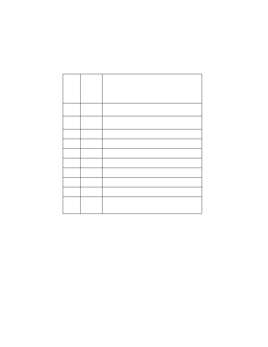
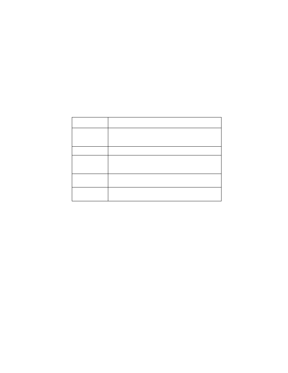
Error Indicator Table
Power-On Self Test (POST) Sequence
When you turn the printer on it performs a POST. Turn your printer
on and check for a correct POST operation by observing the
following:
1. The power light comes on.
2. The carrier moves over the maintenance station and seals the
printheads.
3. The paper feed gears turn.
4. All motors stop and the power light stays on.
Error
Code
Number
of
Power
Light
Flashes
Action
64
65
7
Replace the code module and/or system board and
printhead cable.
66 -
78
6
Replace the code module and/or system board and
printhead cable.
79
9
Replace the Code Module and/or system board.
81
2
Go to the
“Transport Service Check” on page 2-15
83
8
Replace the code module and/or system board.
89
4
Go to the
“Transport Service Check” on page 2-15
90
5
Check the carrier and/or replace the system board.
92
12
Go to the
“Power Service Check” on page 2-11
.
93
3
Replace the code module and/or system board.
127
and
up
10
Replace the Code Module and/or system board.
Diagnostic Information 2-3
4092
If your printer completes POST with no errors, go to the
, locate the symptom and take the indicated
action.
If your printer does not complete POST, locate the symptom in the
following table and take the indicated action.
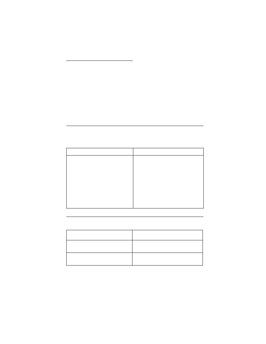
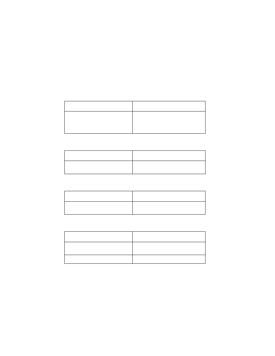
POST Symptom Table
Symptom
Action
No Power light
and no motors
run
Go to the
“Power Service Check” on page 2-11
Feeds paper
Go to the
“First Print Line Service Check” on page 2-6
.
Paper feed
gears do not
turn
Go to the
“Paper Feed Service Check” on page 2-8
.
Carrier doesn’t
move
Go to the
“Transport Service Check” on page 2-15
Carrier slams
side frame
Go to the
2-4
4092
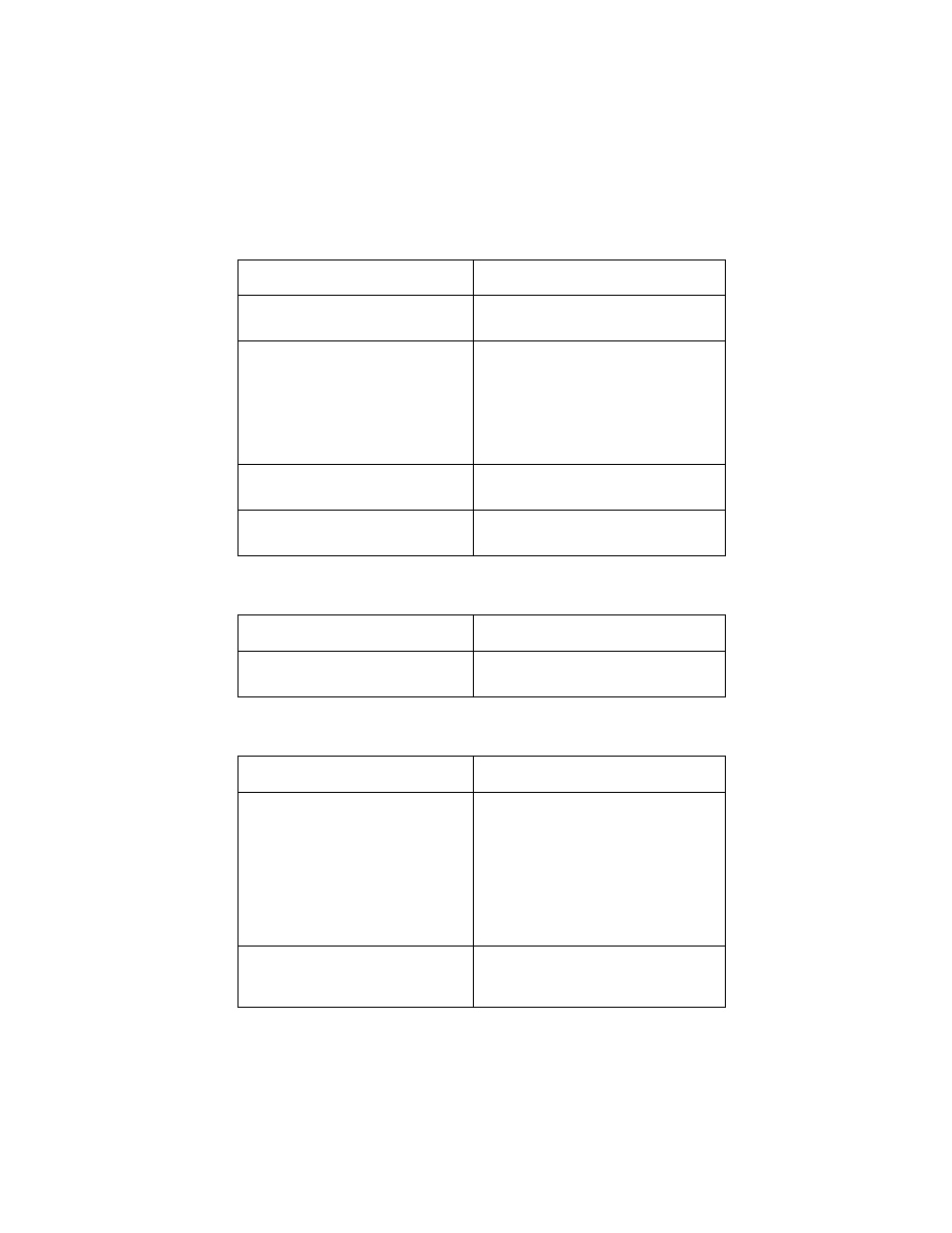
Symptom Tables
Locate the symptom in the following tables and take the appropriate
action.
Carrier Transport Problems
Communications Problems
Maintenance Station Problems
Operator Panel Problems
Symptom
Action
• No carrier movement
• Slow carrier movement
• Carrier stops
• Carrier slams side frame
Go to the
.
Symptom
Action
Printer not communicating with
host computer
Go to the
Symptom
Action
• Fails to cap the printhead
• Fails to clean the printhead
Go to the
Symptom
Action
Paper feed button does not
operate
Replace the system board.
Busy light does not come on
Replace the system board.
Diagnostic Information 2-5
4092
Paper Feed Problems
Power Problems
Print Quality Problems
Symptom
Action
Paper fails to stop at first print line
Go to the
• Fails to pick paper
• Picks more than one sheet of
paper
• Picks paper but fails to feed
• Paper jams
• Paper fails to exit
• Noisy paper feed
Go to the
Envelopes fail to feed
Go to the
Paper skews
Go to the
Symptom
Action
No power in printer, no Power
light, no motors
Go to the
Symptom
Action
• Voids in characters
• Light print
• Prints off the page
• Fuzzy print
• Carrier moves but does not
• Printhead drying prematurely
• Vertical alignment off
• Excessive ink flow (Flooding)
Go to the
• Ink smearing
• Vertical streaks on paper
• Print lines crowded
Go to the
2-6
4092
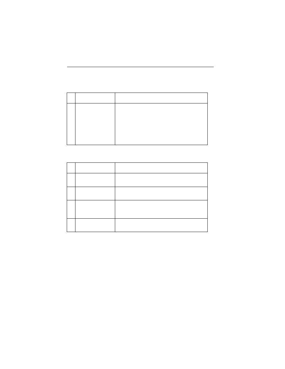
Service Checks
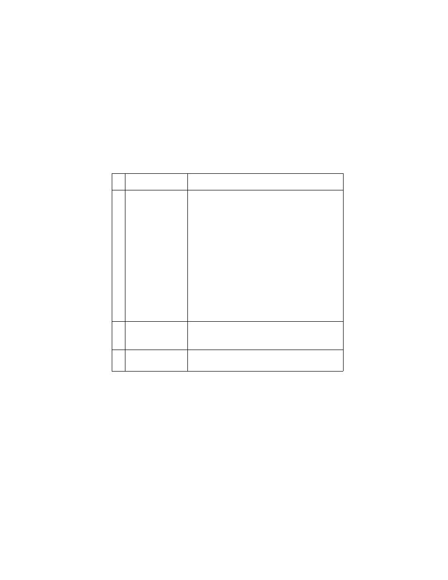
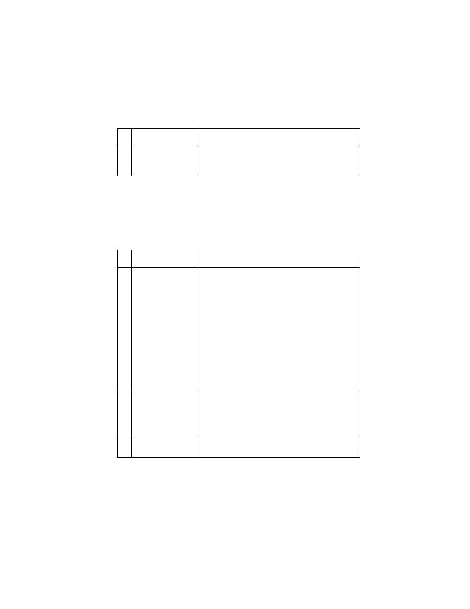
Envelope Feed Service Check
First Print Line Service Check
FRU
Action
1
Envelope Guide
Be sure the envelope guides have been turned
to the envelope load positions.
Be sure the envelope guides are against the
envelopes.
Perform the
.
FRU
Action
1
End-of-Forms
Flag
Check the flag for binds or damage.
2
End-of-Forms
Sensor
Check the sensor for dirt.
3
System Board
Perform the
to check the end-of-forms sensor on
the system board.
4
Feed Arm
Assembly
Check all parts of the feed arm assembly for
binds, wear, or damage.
Diagnostic Information 2-7
4092
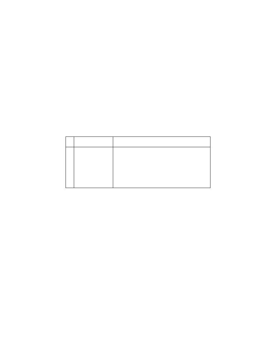
Maintenance Station Service Check
The maintenance station has two functions:
1. Cleans the printhead nozzles during the print operation.
2. Seals the printhead when it is not being used to prevent the
nozzles from drying.
FRU
Action
1
Maintenance
Station Assembly
As the carrier moves to the right over the
maintenance station, a slot on the bottom of the
carrier engages a tab on the sled of the
maintenance station causing the caps to rise and
seal the printheads. Carrier movement to the left
will uncap the printheads. The wipers clean the
printhead nozzles as the carrier leaves the
maintenance station. The wipers clean the
printheads only when the carrier is moving to the
left. There should be no wiping action of the
printhead nozzles when the carrier is moving to
the right. After the cleaning operation is complete,
a tab on the maintenance station engages a tab on
the carrier, causing the wipers to lower.
Check the maintenance station for worn or broken
parts.
2
Wiper
A worn wiper causes degraded print quality just
after a maintenance cleaning. Check for loose or
worn wiper.
3
Cap
A worn cap causes the printhead nozzles to dry
and clog. Check for loose or worn cap.
2-8
4092
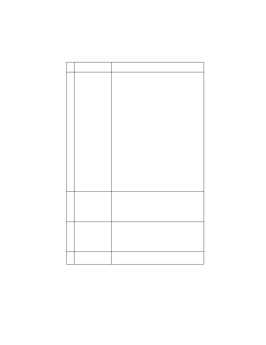
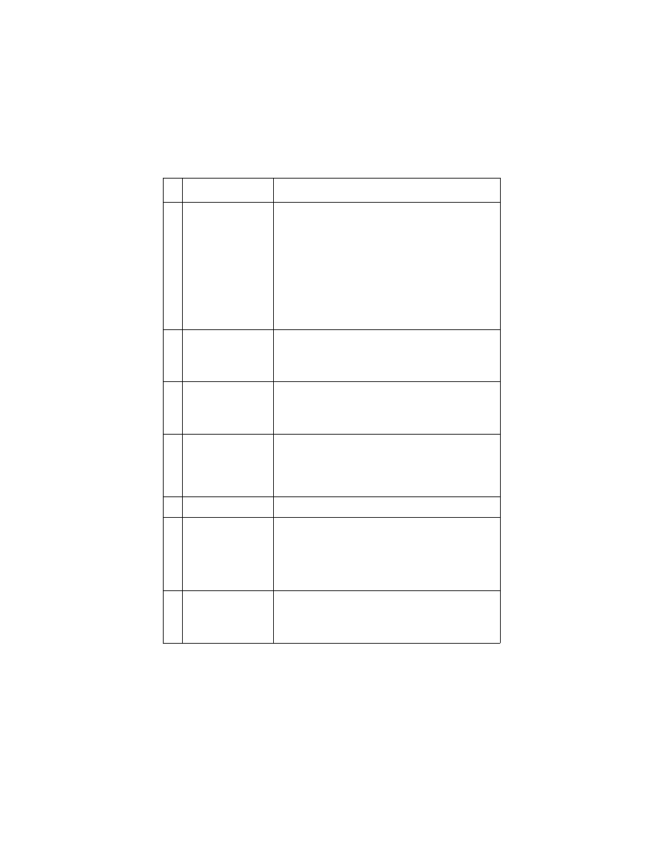
Paper Feed Service Check
If your printer does not have paper jam problems, continue with the
service check. If your printer does have a paper jam problem,
examine it for the following before you begin the service check:
•
Check the entire paper path for obstructions.
•
Be sure there is not too much paper in the sheet feeder.
•
Be sure the correct type of paper is being used.
•
Check for static in the paper.
FRU
Action
1
System Board
With J5 disconnected and power on, check for
+30 V dc between J5-1 and ground, and between
J5-3 and ground on the system board. If the
voltage is not present, check for motor pins
shorted to the motor housing. If you find a shorted
pin, replace the motor. If you still have a failure
after replacing the motor, replace the system
board.
Diagnostic Information 2-9
4092
2
Paper Feed Motor
A noisy or chattering motor or a motor that fails to
turn, can be caused by:
• An open or short in the motor
• An open or short in the motor driver on the
system board
• A bind in the paper feed mechanism
With the paper feed motor cable disconnected
from the system board, check for 5 to 10 ohms
between pin 1 and 4 on the motor cable.
If the reading is incorrect, replace the motor.
Check for motor pins shorted to the motor housing.
If you find a shorted pin, replace the motor. If the
failure remains, replace the system board.
Although the paper feeds in a forward direction
only, the paper feed motor turns in two directions.
If the paper feed motor turns in one direction only,
replace the system board.
Binds in the paper feed motor or gear train can
cause intermittent false paper jam errors. Remove
the paper feed motor and check the shaft for binds.
Also check for loose or worn motor gear.
3
Gears
Check for binds in the gear train and paper feed
mechanism by rotating the large feed roll by hand.
If you notice a bind, isolate it by removing one of
the small idler gears on the inside of the left side
frame. Replace any worn or binding gears or
rollers.
4
Feed Arm
Assembly
At the beginning of the paper feed operation, the
paper feed motor reverses momentarily to allow
the feed arm pawl to drop off the home position
notch in the left side frame. If the pawl fails to drop
off the notch, check the feed arm assembly for
binds, and worn or broken parts.
5
Paper Path
Perform the
“Paper Path Service Check” on page
, starting at Step 1.
FRU
Action
2-10
4092
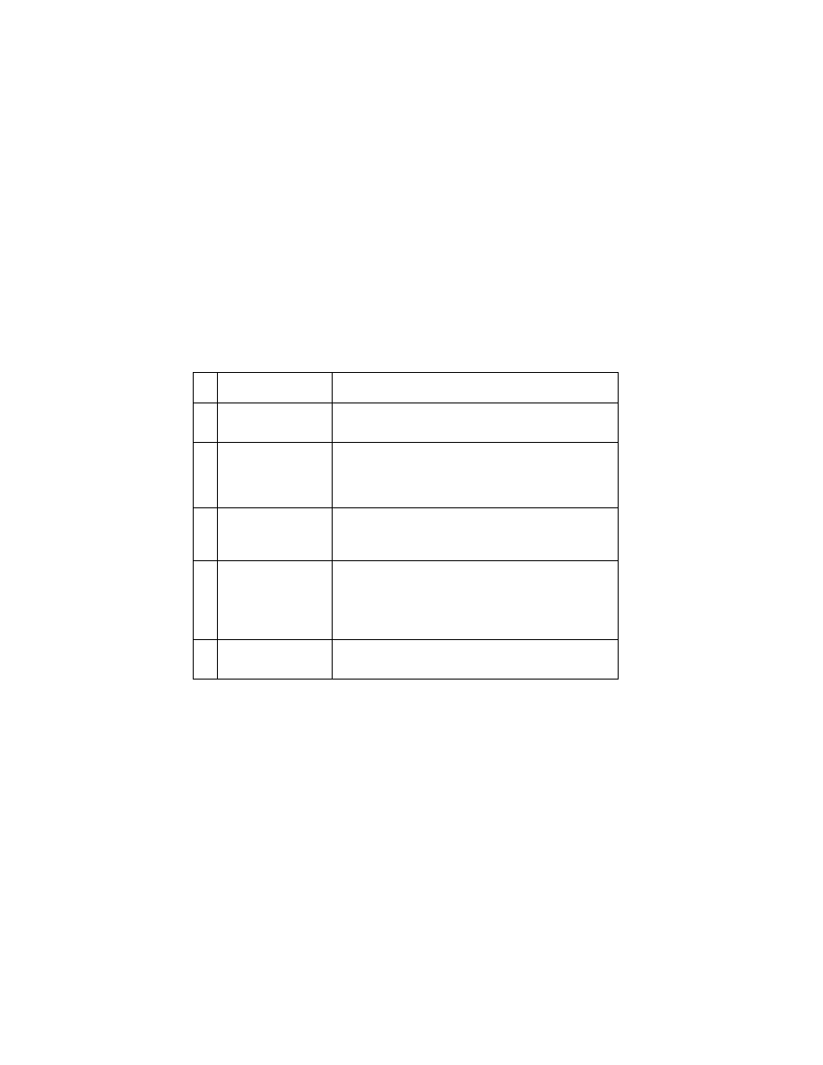
Paper Path Service Check
Examine the printer for the following before you begin this service
check:
•
Check the entire paper path for obstructions.
•
Be sure the paper guides are not worn or broken and are posi-
tioned against the paper without binding or buckling the paper.
•
Be sure the correct type of paper is being used.
•
Be sure the printer is installed on a flat surface.
FRU
Action
1
Large and Small
Feed Rollers
Check for wear and binds.
2
Small Feed Roller
Springs
Paper Guide
Paper Flap
Check for damage.
3
Exit Roller
Star Rollers
Exit Drive Belt
Check for wear and binds.
4
Sheet Feeder
Check the following for wear or damage:
• Pick Rollers
• Envelope Bucklers
• All parts inside the left and right edge guides.
5
End-of-Forms
Flag & Spring
Check for binds or damage.
Diagnostic Information 2-11
4092
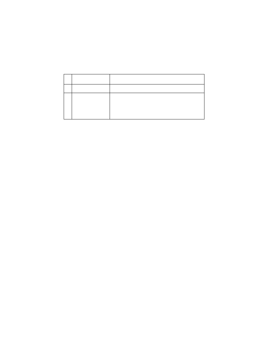
Parallel Port Service Check
Power Service Check
An Error Code 92 is caused by a shorted Print Cartridge, or a short
in the circuit to the Print Cartridges. If the problem is an Error Code
92, replace the Print Cartridges. Continue with this Service Check if
the symptom does not change.
FRU
Action
1
Parallel Port
Run a test page to be sure the printer can print.
Run the
“Parallel Port Test” on page 3-5
. If the test
fails, replace the system board.
FRU
Action
1
Print Cartridges
Power Supply
If the problem is an Error Code 92, replace the
print cartridges.
Disconnect J9 from the system board and check
the following voltages on the power supply cable:
• J9-1 to GND = +5 V dc
• J9-2 to GND = +30 V dc
• J9-4 to GND = +11.75 V dc
If you do not have correct voltage, replace the
power supply. Be sure to unplug the printer before
you reconnect the power supply to the system
board.
3
Printhead Cable
Parallel Cable
Encoder Card
Turn off the printer. Disconnect one of the
printhead cables and turn on the printer. Look for a
symptom change. Check the failing part for shorts
and replace as necessary. Repeat this procedure
for the parallel cable and the encoder card.
4
System Board
If the symptom has not changed, replace the
system board.
2-12
4092
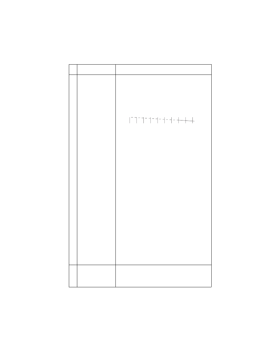
Print Quality Service Check
FRU
Action
1
Print Cartridge
Be sure the printer contains good print cartridges.
2
Printhead Carrier
Assembly
Reseat the printhead cables in the system board
and check the following parts for wear or damage:
• Print Cartridge Latch
• Latch Spring
• Carrier
Diagnostic Information 2-13
4092
3
System Board
Printhead Cable
Rubber Backer
Thermal Sensor
• Perform the
. Look for a
break in the diagonal line of the test pattern. A
broken line indicates one or more print nozzles
are not working. Run the test again to verify the
failure. If there are even breaks in the diagonal
line similar to the pattern shown below, replace
the system board.
If there is a single break or random breaks in the
diagonal line check the following:
• Check the gold-plated contacts, on the end of
the cable that connect to the carrier, for dirt and
wear. Use only a clean dry cloth to clean the
contacts. Also check the cable for damage. You
may need to remove the cable from the carrier
to inspect it.
• A worn rubber backer results in poor contact
between the printhead cable and the print
cartridge. Check the rubber backer for wear.
• Refer to the test page. The temperature value in
Celsius, or the message “Thermal Sensor Not
Installed” is printed. If the thermal sensor is not
installed or malfunctioning, and the printer is
operating in a warm environment > 104F (40C),
excessive ink may flow from the cartridge. Be
sure the thermal sensor is connected to J7 on
the system board.
If the thermal sensor is connected and a
“Thermal Sensor Not Installed” message prints,
replace the thermal sensor.
Note: Printing slows to prevent overheating and
excessive ink flow, when the temperature is
above the normal operating range, or when
printing complex graphics.
The normal operating temperature range is
60 F to 90 F (16 C to 32 C).
4
Maintenance
Station
Intermittent nozzle failures can be caused by worn
parts in the maintenance station. Perform the
“Maintenance Station Service Check” on page 2-7
,
then return to this check.
FRU
Action

2-14
4092
5
Paper Feed
Ink smudging and smearing can be caused by
paper problems or problems in the paper feed
area.
Check the following:
• Correct type of paper is being used.
• Paper for curl or wrinkles.
• Feed rollers for wear, dirt, or looseness.
• Gears for wear or binds.
• Paper path for obstructions.
6
Transport
Blurred print and voids can be caused by problems
in the transport area. Check the following:
• Transport belt for wear and full engagement into
the carrier grip.
• Carrier guide rod for wear or dirt.
• Carrier to carrier frame engagement should be
lubricated with grease P/N 1329301.
Lubricate the carrier guide rod and carrier frame
on both sides where the two top bearing
surfaces ride on the frame.
• Idler pulley parts for wear, damage, or
looseness.
• Encoder strip for wear or dirt.
7
Alignment
Uneven vertical lines can be adjusted by
performing the bidirectional alignment. The user is
directed, through the Printer Control program, to
perform the head to head and bidirectional printing
alignments, when replacing a print cartridge.
FRU
Action
Diagnostic Information 2-15
4092
Transport Service Check
FRU
Action
1
Transport Motor
Check the motor for binds, or loose motor pulley.
Disconnect the transport motor (J4) from the
system board. Check for 8 to 18 ohms between
pins 1 and 2 on the motor cable. If the reading is
incorrect, replace the motor.
Check for motor pins shorted to the motor housing.
If you find a pin shorted to the housing, replace the
motor. If the failure remains, replace the system
board.
2
System Board
Turn the printer off and disconnect J4 from the
system board. Turn the printer on and check for a
pulse of 6 to 8 V dc between J4-1 and ground as
the printer goes through POST.
3
Carrier Guide Rod
Clean the carrier rod.
Note: Lubricate the rod and the carrier rod bearing
surface.
4
Transport Belt
Idler Pulley Parts
Carrier Frame
Check for worn, loose or broken parts. Check for
obstructions blocking carrier movement.
Carrier to carrier frame engagement should be
lubricated with grease P/N 1329301.
5
Encoder Strip
Check for wear and dirt.
6
Printhead Cable
Encoder Strip
Encoder Card
System Board
Be sure all connectors are fully seated. Check the
cables for damage.
Perform the
“Encoder Sensor Test” on page 3-2
. If
you cannot enter the test, replace the system
board.
7
Maintenance
Station
A problem with the maintenance station can cause
carrier movement problems at the right margin. Go
to the
“Maintenance Station Service Check” on
.
2-16
4092
Video Service Check
FRU
Action
1
Video Board
(4092-005)
Print a job from a different application.
Perform a
.
Check the cable between the video board and
system board.
Check the video source connections.
If the cable and all connections are good, replace
the video board.

Diagnostic Aids 3-1
4092
3. Diagnostic Aids
Use these diagnostic test procedures to verify a repair. There are
two ways to enter test procedures, each procedure will indicate the
method to use:
Procedure 1:
•
Press and hold the Paper Feed button while turning the printer
on. Release the button when the printer completes POST.
Procedure 2:
•
Turn the printer off.
•
Use a two pin jumper on connector J6.
•
Turn the printer on. The test begins when the Power Button is
pressed.
A two pin jumper is also available in the parts packet,
13B0239.

3-2
4092
Encoder Sensor Test
This test disables the printer motors to let you manually move the
carrier to verify the encoder is working correctly.
To run the test:
1. Turn the printer off and place a two pin jumper on connector J6
as shown below. (Pins 1 & 2).
2. Ensure the manual paper slot is empty.
3. Press and hold the Paper Feed button while turning the printer
on and continue to hold until the Busy Light begins to flash.
•
Manually moving the carrier to the left causes the Power
Light to flash.
•
Manually moving the carrier to the right, causes the Busy
Light to remain on.
If the test fails power off the printer and remove the carrier
assembly without unplugging the printhead cable.
Power on the printer and check for +5 V dc at pins 1, 2 and 3 of the
encoder card connector. See “Connector Locations on page 5-1.”
1. If voltage is not present, check the printhead cable for opens to
the encoder card. If the printhead cable is good, replace the
system board.
2. If voltage is present, check the sensor on the encoder card by
monitoring pin 3 of the encoder card connector as you pass a
piece of paper through the sensor. The voltage should go from
+5 V dc to 0 V dc. Turn the power off and back on to make this
check again. If the voltage at pin 3 does not change, replace the
encoder card. If the symptom remains, replace the printhead
cable.

Diagnostic Aids 3-3
4092
Initialize Error Log
This test lets you track new errors.
Use this procedure to reset the error log to zero. The error log is
especially helpful in diagnosing intermittent or difficult problems.
To run the test:
1. Turn the printer off and place a two pin jumper on connector J6
as shown below. (Pins 3 & 4).
2. Place a sheet of paper in the manual feed far enough to activate
the EOF (End of Forms) sensor.
3. Press the Power Button. When the Power Light begins to flash,
the Error Log clear is complete. (This may take several
seconds). To stop the test, turn power off or unplug the printer.

3-4
4092
End of Forms (EOF) Test
This test checks the EOF sensor on the system board.
During the test, the power light blinks rapidly. The Busy Light shows
the EOF sensor status in the following manner:
•
On - paper is in sensor
•
Off - paper is not in sensor
To run the test:
1. Turn the printer off and place a two pin jumper on connector J6
as shown below. (Pins 3 & 4).
2. To start the test, press and hold the Paper Feed button while
turning the printer on. Hold the button until the Power Light
blinks rapidly. Turn power off or unplug the printer to stop the
test.

Diagnostic Aids 3-5
4092
Parallel Port Test
This test performs a wrap around test between the printer parallel
port and the parallel port test connector.
This test requires a parallel port wrap plug. Install the wrap plug in
the parallel port and move the jumper to pins (1 & 2) on the test
connector, before you start the test.
To run the test:
1. Turn the printer off.
2. Attach the wrap plug to the parallel port.
3. Place a two pin jumper on pins (1 & 2) of test connector J6.
4. Turn the printer on.
If the lights blink alternately, the test is failing. If the Busy Light stays
on and the Power Light blinks, the test is working properly. If the
Busy Light blinks intermittently, an intermittent failure is occurring.

3-6
4092
Print NVRAM Contents
This test prints the contents of NVRAM in hexadecimal format.
To run the test:
1. Turn the printer off and place a piece of paper in the manual
feed far enough to activate the EOF sensor.
2. To start the test, press and hold the Paper Feed button while
turning the printer on. Release the button when the printer
completes POST.
The device ID is shown on the right side of the printout.
The following appears below the printout:
•
Code Level
•
Code Date
•
Last Error
•
Page Count

Diagnostic Aids 3-7
4092
Test Page
This test prints the test page.
To run a complete test page of black and color patterns, be sure the
print cartridges are in good condition. Install a black print cartridge in
the left side of the printhead cradle and a color print cartridge in the
right side.
To enter the test:
1. Turn the printer off.
2. Ensure the manual paper slot is empty.
3. To start the test, press and hold the Paper Feed button while
turning the printer on. Release the button when the printer
completes POST.
The test page contains the following:
•
Code level and date
•
Current printhead temperature in Celsius
(read by the thermal sensor board)
•
Nozzle test pattern for both cartridges
•
Purge test for both cartridges
•
Text (printer model)
•
Paper test result
(for manufacturing purposes only)

Repair Information 4-1
4092
4. Repair Information
This chapter explains how to make adjustments to the printer and
how to remove defective parts.
Note: Read the following before handling electronic parts. When
working on the printer, always unplug the printer from the wall outlet.
High voltage is present in the power supply as long as it is plugged
into the wall outlet.
Handling ESD-Sensitive Parts
Many electronic products use parts that are known to be sensitive to
electrostatic discharge (ESD). To prevent damage to ESD-sensitive
parts, follow the instructions below in addition to all the usual pre-
cautions, such as turning off power before removing logic boards:
•
Keep the ESD-sensitive part in its original shipping container (a special
“ESD bag”) until you are ready to install the part into the printer.
•
Make the least-possible movements with your body to prevent an
increase of static electricity from clothing fibers, carpets, and furniture.
•
Put the ESD wrist strap on your wrist. Connect the wrist band to the
system ground point. This discharges any static electricity in your body
to the printer.
•
Hold the ESD-sensitive part by its edge connector shroud (cover); do
not touch its pins. If you are removing a pluggable module, use the
correct tool.
•
Do not place the ESD-sensitive part on the printer cover or on a metal
table; if you need to put down the ESD-sensitive part for any reason,
first put it into its special bag.
•
Printer covers and metal tables are electrical grounds. They increase
the risk of damage because they make a discharge path from your
body through the ESD-sensitive part. (Large metal objects can be
discharge paths without being grounded.)
•
Prevent ESD-sensitive parts from being accidentally touched by other
personnel. Install printer covers when you are not working on the
printer, and do not put unprotected ESD-sensitive parts on a table.
•
If possible, keep all ESD-sensitive parts in a grounded metal cabinet
(case).
•
Be extra careful in working with ESD-sensitive parts when cold weather
heating is used because low humidity increases static electricity.
Repair Information 4-2
4092
Adjustments
The user is directed, in the Printer Control program, to perform the
head to head and bidirectional alignment adjustments after replacing
a print cartridge.
Removal Procedures
The following procedures are arranged according to the name of the
printer part discussed. Unplug the power cord before removing any
parts.
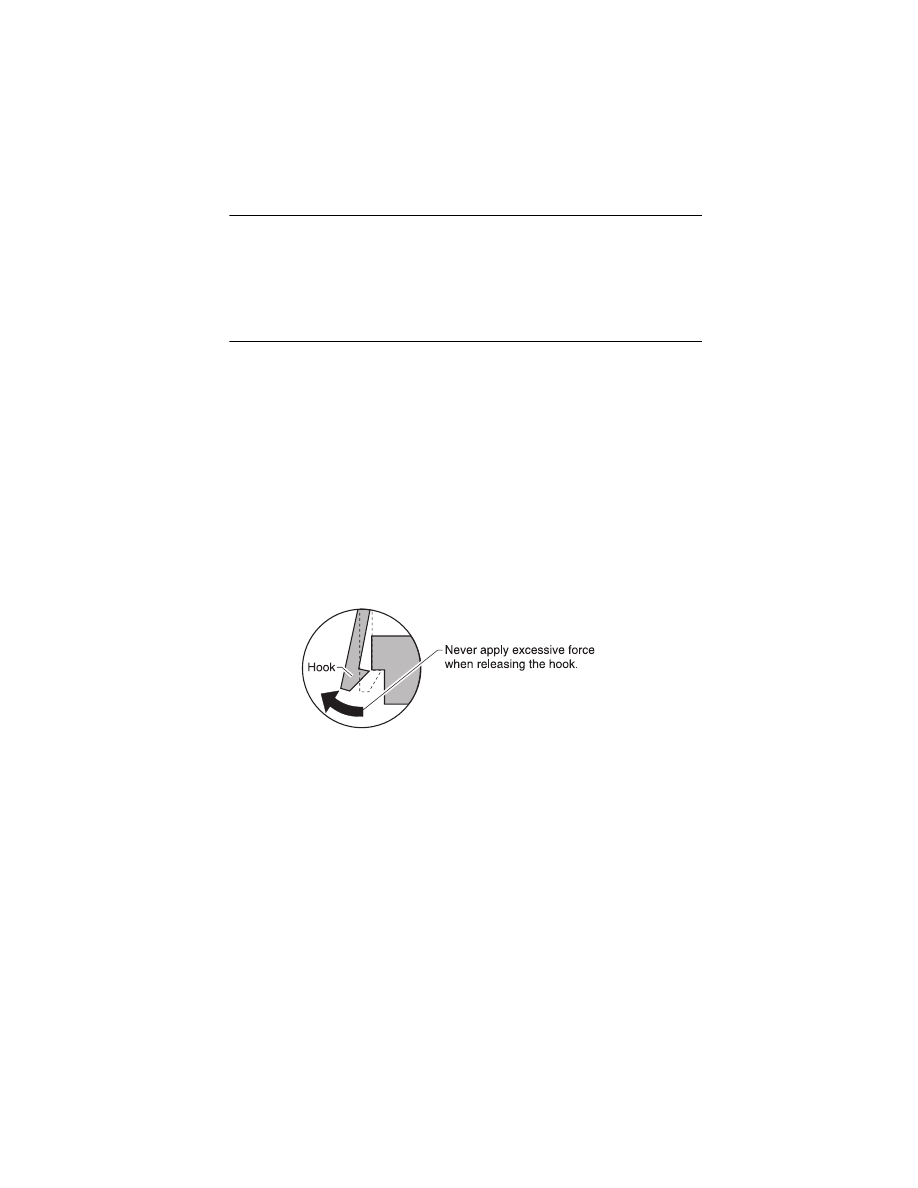
Releasing Plastic Latches
Many of the parts are held in place with plastic latches. The latches
break easily; release them carefully. To remove such parts, press the
hook end of the latch away from the part to which it is latched.

4-3
4092
Base Assembly Removal
1. Remove the front cover.
2. Remove the rear cover.
3. Disconnect the power supply connector at the system board.
4. Remove the two screws from the maintenance station
assembly. Pull up the right side of the mid frame assembly and
pull forward and remove the maintenance station assembly.
5. Remove the two screws securing the carrier frame to the base
cover.
6. Slide the printer off the base cover.
Carrier Belt Removal
1. Remove the front cover.
2. Remove the printhead carrier assembly.
3. Push the idler pulley to the right to release the tension on the
belt and remove the belt.
Note: When reinstalling the carrier belt, place the carrier at the
center position between the tabs on either end of the belt.
Repair Information 4-4
4092
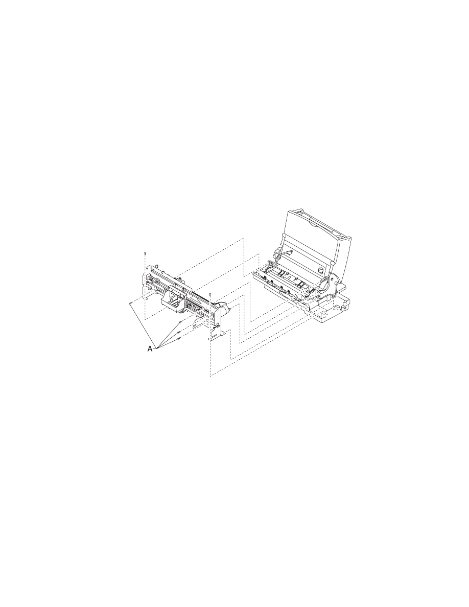
Carrier Frame Assembly Removal
1. Remove the front cover.
2. Remove the rear cover.
3. Remove the base assembly.
4. Disconnect the paper feed motor and power supply connectors
from the system board.
5. Remove the four screws [A] securing the carrier frame to the left
and right side frames and remove the carrier frame assembly.
4-5
4092
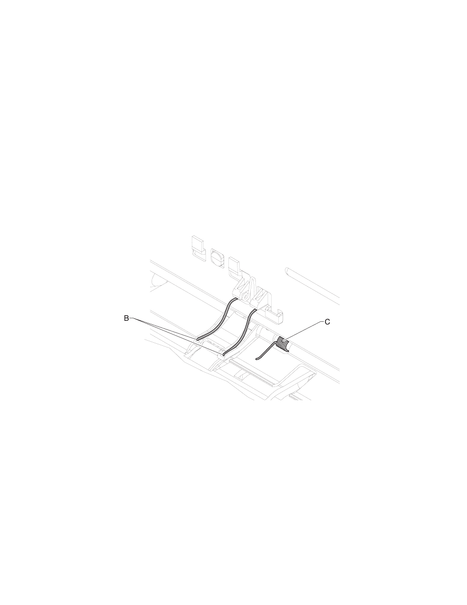
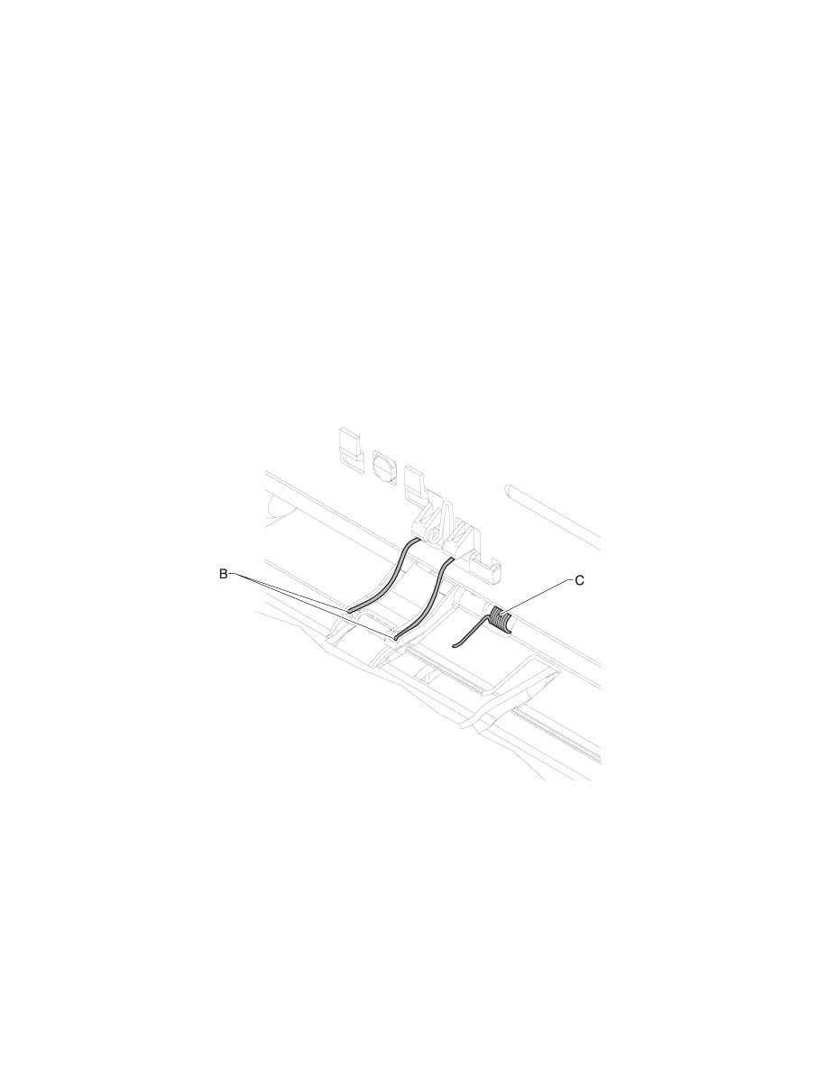
Note: During reassembly:
1. Be sure the small feed roll spring extensions [B] are in the
grooves of the small feed roll arms.
2. Be sure the short extensions of the two paper flap springs are
trapped under the carrier frame [C].
3. Be sure the tab from the paper guide does not deflect the small
feedroll shaft downward. The shaft should be forward of the tab.
Carrier Transport Motor Removal
1. Remove the front cover.
2. Disconnect the transport motor connector from the system
board.
3. Remove the belt from the transport motor pulley.
4. Remove the two screws securing the transport motor to the
carrier frame and remove the motor. Note the routing of the
motor cable.

Repair Information 4-6
4092
Code Module Removal
1. Remove the front cover.
2. Remove the rear cover.
3. Gently pry the Code Module from the system board noting the
position of the notch in the module. The notch is down.
Edge Guide Asm and Paper Load Shaft Removal
1. Remove the front cover.
2. Remove the rear cover.
3. Remove the paper load door and manual insert tray.
4. Remove the pick roll hub, shaft and envelope bucklers.
5. Remove the two screws from the right side frame.
6. Work the paper load shaft out of the side frames.
7. Pull up the bottom of the edge guides to separate them from the
top of the back plate and remove the assembly from the frames.
Note: When reinstalling, be sure the edge guide springs are turned
to the inside to maintain spring tension on the guides.
Encoder Card Removal
1. Remove the front cover.
2. Remove the printhead carrier assembly.
3. Disconnect the printhead cable from the encoder card.
4. Remove the screw from the encoder card and remove the card.
Encoder Strip Removal
1. Remove the front cover.
2. Remove the printhead carrier assembly.
3. Gently release the tension on the encoder strip by flexing the
encoder strip tensioner and remove the encoder strip.
Note: When reinstalling the encoder strip, make sure the ends of
the strip are centered in their mounting notches and the strip does
not bind in the encoder card on the carrier.

4-7
4092
Exit Drive Belt Removal
1. Remove the front cover.
2. Remove the rear cover.
3. Remove the carrier frame assembly.
4. Remove the paper load door and manual insert tray.
5. Remove the small feed roll shaft.
6. Remove the two screws from the star roller assembly and
remove the assembly.
7. Unlatch the left side of the exit roller shaft and work the belt off
the exit roller pulley.
8. Pull up the four clips securing the mid frame to the large feed
roll and work the mid frame out of both side frames.
9. Spread the right side frame apart far enough to allow removal of
the exit drive belt.
Exit Roller Removal
1. Remove the front cover.
2. Remove the two screws from the star roller assembly and
remove the assembly.
3. Unlatch the left side of the exit roller and remove the exit drive
belt from the exit roller pulley.
4. Remove the exit roller.
Feed Arm Assembly Removal
1. Remove the front cover.
2. Remove the rear cover.
3. Remove the C-clip from the feed arm and remove the assembly.
Repair Information 4-8
4092
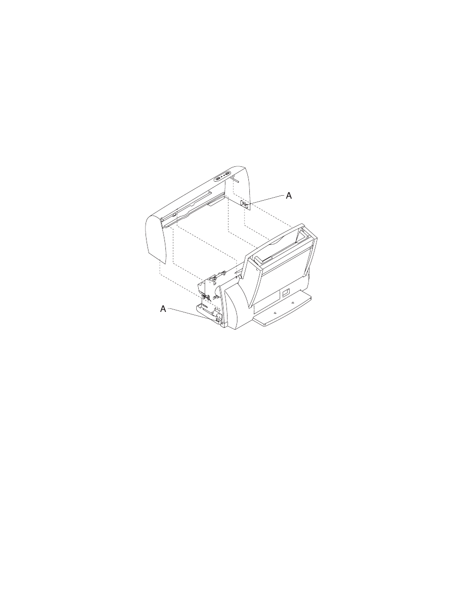
Front Cover Removal
1. Place a screwdriver in slot [A] and release the cover latches.
2. Slide the cover forward and off the printer.
To reassemble:
1. Slide the cover over the matching pieces on the bottom cover.
2. Press in both sides opposite the cover latches until they latch.
Gutter Pad Removal
1. Remove the front cover.
2. Remove the rear cover.
3. Remove the base assembly.
4. Scrape the old gutter pad off the base.

4-9
4092
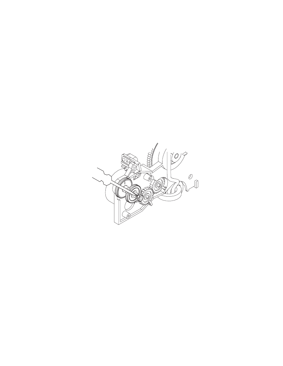
Inside Idler Gears Removal
1. Remove the front cover.
2. Remove the rear cover.
3. Remove the printer from the base assembly.
4. Remove the paper feed motor.
5. Gently pry the two idler gears from the left side frame.
Repair Information 4-10
4092
Large Feed Roll Removal
1. Remove the front cover.
2. Remove the rear cover.
3. Remove the carrier frame assembly.
4. Using a small screwdriver, pry open the slot in the retainer clip
and remove it and the compound idler gear from the compound
idler stud.
5. Remove the large feed roll from the mid frame by pulling it out of
the four mounting clips. Spread the right side frame and remove
the large feed roll.
Note: Install the compound idler gear and retainer clip after the
printer is installed in the base assembly.
4-11
4092
Large Outside Gear Removal
1. Remove the front cover.
2. Remove the rear cover.
3. Remove the paper load door and manual insert tray.
4. Remove the C-clip from the feed arm assembly and remove the
feed arm assembly.
5. Remove the C-clip from the left side of the pick roll shaft.
6. Pull the pick roll shaft out far enough to remove the large gear.
Note: Gently pull the feed arm guide [A] on the left side frame
forward, then remove the large gear.
Repair Information 4-12
4092
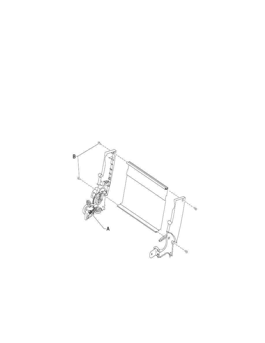
Left Side Frame Assembly Removal
1. Remove the front cover.
2. Remove the rear cover.
3. Remove the carrier frame assembly.
4. Remove the paper load door and manual insert tray.
5. Using a small screwdriver, pry open the slot in the retainer clip
[A] and remove it and the compound idler gear from the
compound idler stud.
6. Remove the two screws [B] securing the left side frame to the
back plate. Slide the left side frame off the back plate. Note the
relationship of the parts.

4-13
4092
Maintenance Station Assembly Removal
1. Remove the front cover.
2. Remove the rear cover.
3. Remove the two screws from the maintenance station
assembly, lift up the right side of the mid frame assembly and
slide the maintenance station assembly forward, out of the
printer.
Maintenance Wipers and Caps Removal
1. Remove the front cover.
2. Push the carrier to the left away from the maintenance station.
3. Gently pull the caps and wipers off their mountings.
Note: When reinstalling the caps, be sure the cap is positioned with
the locking tabs to the left and right before pushing them down on
their mounting posts. Be sure the wipers are completely seated.
Manual Insert Tray Removal
1. Remove the front cover.
2. Remove the rear cover.
3. Remove the paper load door.
4. Spread the right side frame away from the manual insert tray
until the pins in the insert tray clear the frame.
5. Remove the manual insert tray from the left side frame.
Mid Frame Assembly Removal
1. Remove the front cover.
2. Remove the rear cover.
3. Remove the carrier frame assembly.
4. Remove the paper load door and manual insert tray.
5. Remove the small feed roll shaft.
6. Remove the two screws from the star roller assembly and
remove the assembly.
7. Unlatch the left side of the exit roller shaft and work the belt off
the exit roller pulley.
8. Pull up the four clips securing the mid frame to the large feed
roll and work the mid frame out of both side frames.
Repair Information 4-14
4092
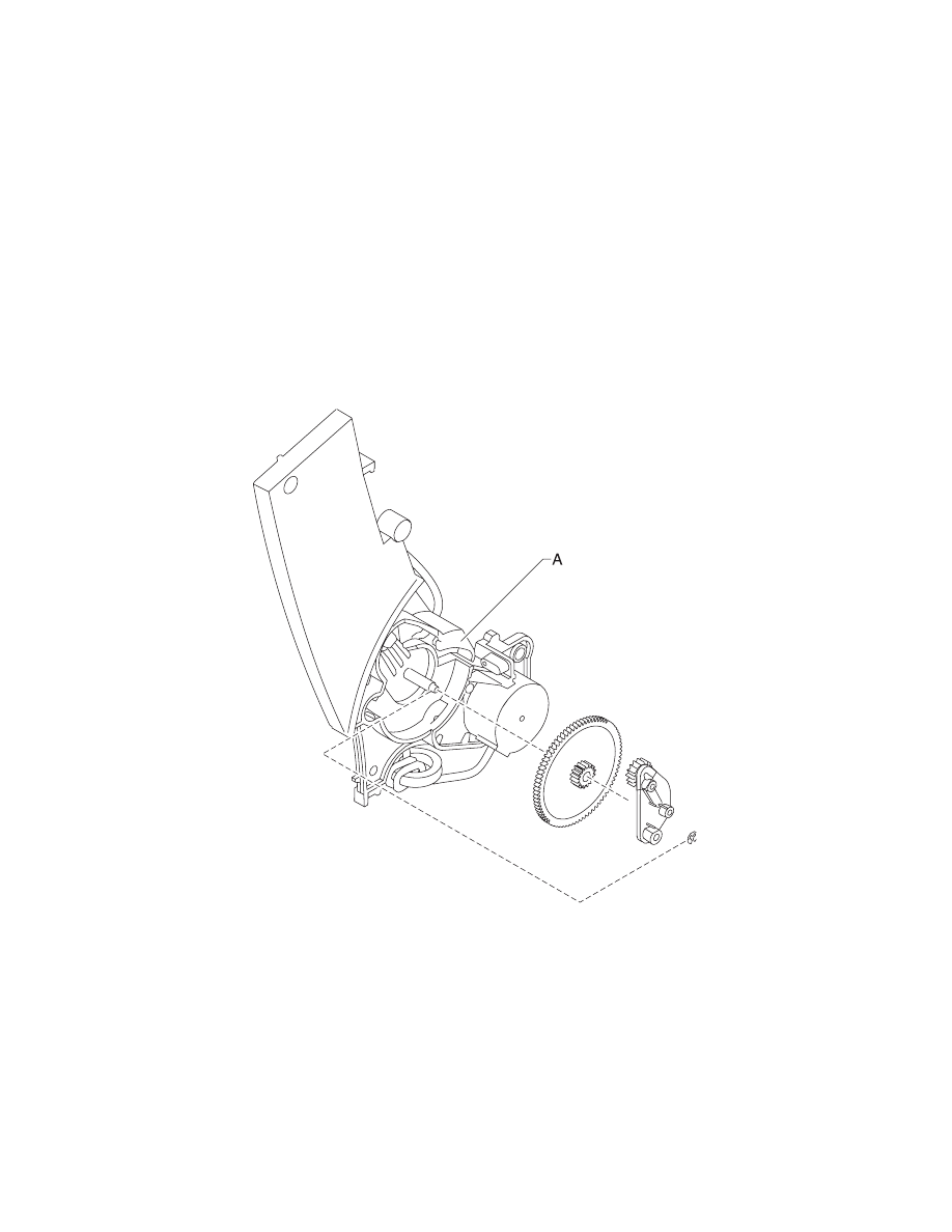
Paper Feed Motor Removal
1. Remove the front cover.
2. Remove the rear cover.
3. Remove the base assembly.
4. Remove the two screws securing the paper feed motor and
remove the motor. Note the routing of the motor cable.
Paper Guide and EOF Flag Assembly Removal
1. Remove the front cover.
2. Remove the rear cover.
3. Remove the printhead carrier assembly.
4. Remove the carrier frame assembly.
5. Remove the encoder strip.
6. Remove the system board.
7. Remove the three small feed roll springs.
8. Push the locking tabs [A] to the rear and pull the paper guide
down and out of the carrier frame.
4-15
4092
Note: During reassembly:
1. Be sure the small feed roll spring extensions [B] are in the
grooves of the small feed roll arms.
2. Be sure the short extensions of the two paper flap springs are
trapped under the carrier frame [C].
3. Be sure the tab from the paper guide does not deflect the small
feedroll shaft downward. The shaft should be forward of the tab.

Repair Information 4-16
4092
Paper Load Door Removal
Spread the left side frame where it joins the paper load door and
remove the door.
Pick Roll Shaft, Hub and Envelope Bucklers Removal
1. Remove the front cover.
2. Remove the rear cover.
3. Remove the paper load door and manual insert tray.
4. Slide the left paper guide to the right.
5. Remove the C-clip from the left side of the pick roll shaft.
6. Pull the pick roll shaft out to the left and remove the pick roll
shaft, hubs and envelope bucklers.
Note: During reassembly, be sure the pick roll hubs are in the slots
at the bottom of the paper guides and the rolls are centered on the
pick pads.
Power Supply Removal
Note: When working on the printer, always unplug the printer from
the wall outlet. High voltage is present in the power supply as long
as it is plugged into the wall outlet.
1. Remove the front cover.
2. Remove the rear cover.
3. Remove the base assembly.
4. Turn the base over, pull out on the latches, slide the power
supply forward and off the base assembly.
4-17
4092
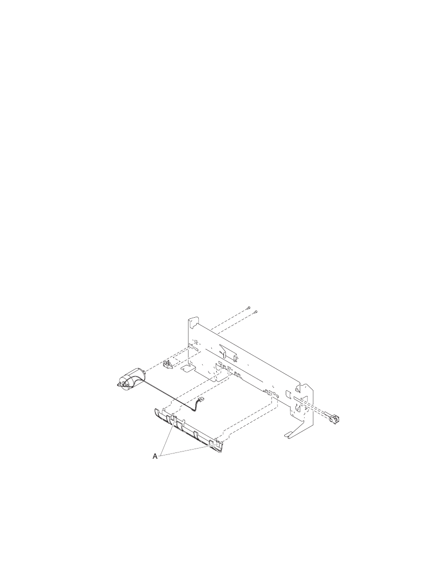
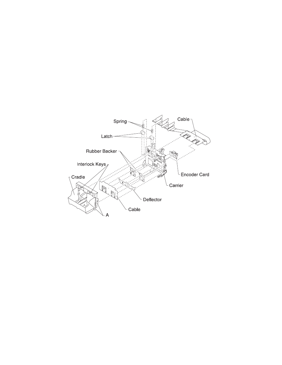
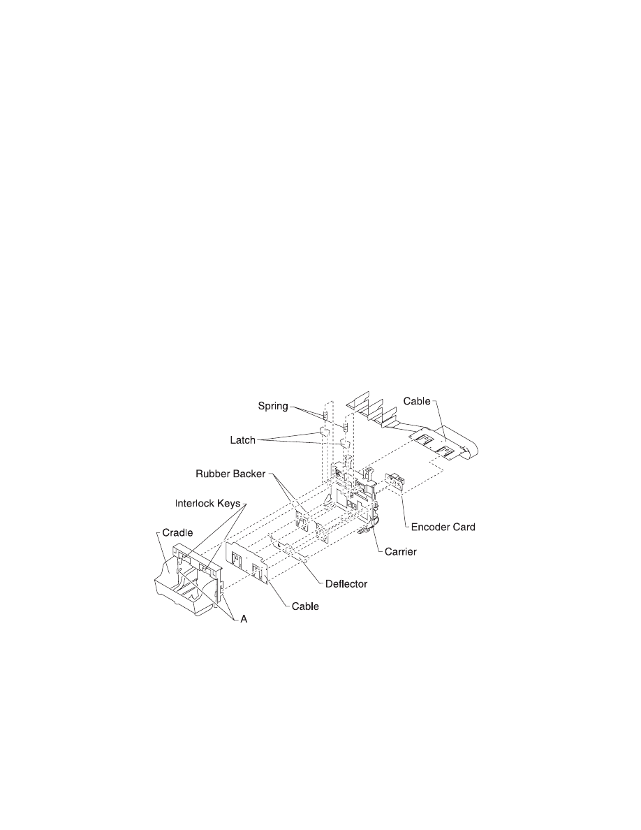
Printhead Cable, Cradle & Paper Deflector Removal
1. Remove the front cover.
2. Remove the printhead carrier assembly.
3. Disconnect the printhead cable from the encoder card. Note the
routing of the cable under the retaining clip on the carrier.
4. Separate the cradle from the printhead carrier assembly by
pushing out the cradle latches [A].
5. Feed the folded end of the printhead cable through the opening
in the carrier assembly and remove the cable.
Note: Use the illustration to assemble the carrier parts in the correct
sequence.
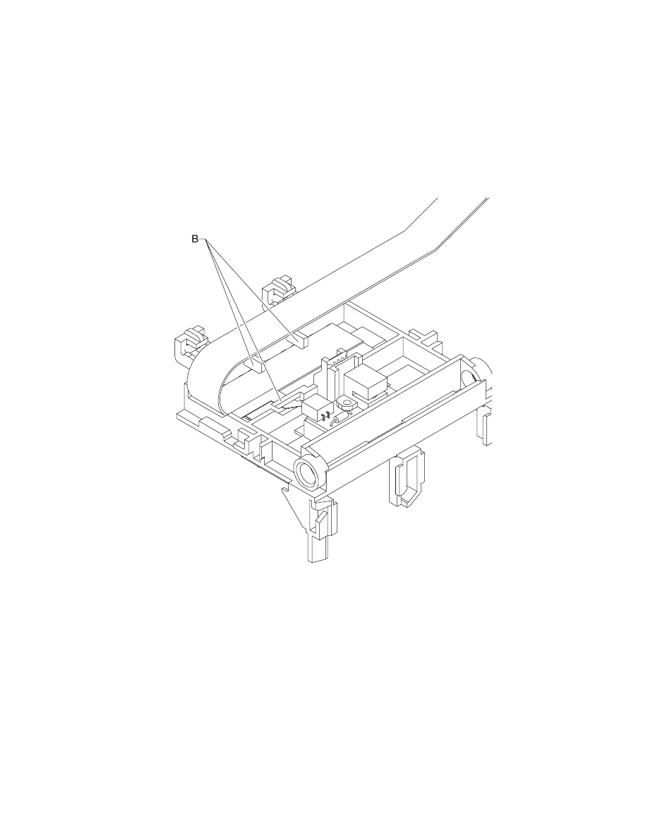
Repair Information 4-18
4092
Note: Be sure the cable is secured under the three retaining clips
[B] on the back of the carrier.
4-19
4092
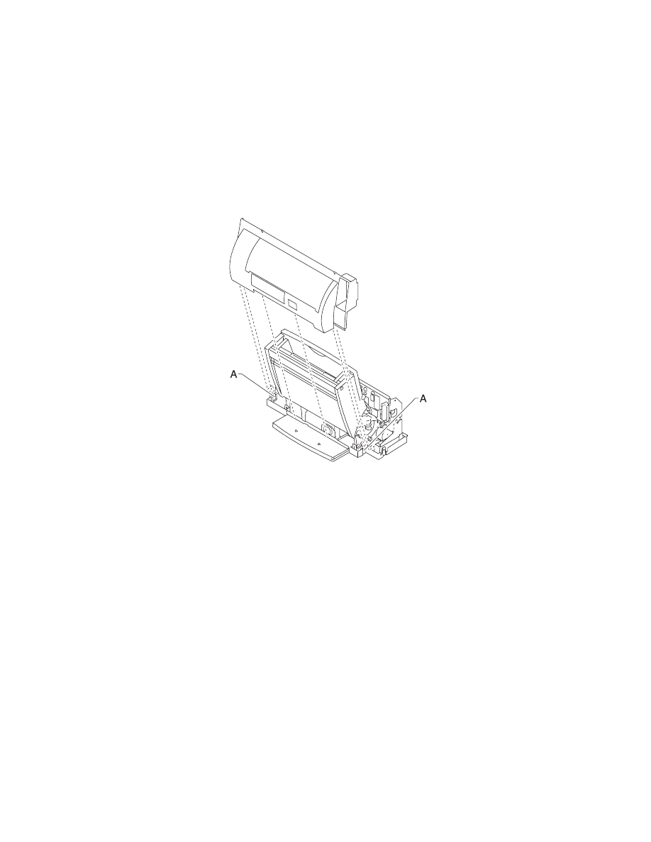
Printhead Carrier Assembly Removal
1. Remove the front cover.
2. Unlock the three printhead cable connectors and disconnect the
printhead cable from the system board.
3. Remove the screws from the ends of the carrier guide rod and
move the carrier to the left.
4. Remove the carrier guide rod by lifting the right end of the rod
while spreading the right side of the carrier frame.
5. Remove the carrier assembly by lifting upward, taking care to
clear the encoder strip before pulling the carrier assembly out.
Printhead Rubber Backer Removal
1. Remove the front cover.
2. Remove the printhead carrier assembly.
3. Separate the cradle from the printhead carrier assembly by
pushing out the cradle latches [A].
4. Remove the rubber backer and paper deflector from under the
printhead carrier cable. Note: Use the illustration to assemble
the carrier parts in the correct sequence.
Repair Information 4-20
4092
Rear Cover Removal
1. Remove the front cover.
2. Place a screwdriver in slot [A] and release the cover latches.
3. Slide the cover up and off the printer.
4. To reassemble, place the cover over the tabs in the bottom
cover and press down until the cover latches. Be sure the
parallel connector snaps do not get trapped behind the cover.
Right Side Frame Assembly Removal
1. Remove the front cover.
2. Remove the rear cover.
3. Remove the carrier frame assembly.
4. Remove the paper load door and manual insert tray.
5. Remove the two screws securing the right side frame to the
back plate. Slide the right side frame off the back plate. Note the
relationship of the parts.

4-21
4092
Small Feed Roll Shaft, Rollers & Paper Flap Removal
1. Remove the front cover.
2. Remove the rear cover.
3. Remove the carrier frame assembly.
4. Spread the left and right side frames apart far enough to
remove the small feed roll shaft assembly.
Star Roller Removal
1. Remove the front cover.
2. Remove the three screws from the star roller assembly and
remove the assembly.
System Board Removal
1. Remove the front cover.
2. Unlock the three printhead cable connectors and disconnect the
printhead cables from the system board.
3. Disconnect the other cables from the system board.
4. Gently release the tension on the encoder strip by flexing the
encoder strip tensioner and remove the encoder strip from the
left side only.
5. Remove the three screws securing the system board to the
carrier frame and remove the system board. Note the routing of
the paper feed motor cable. Pull the EOF flag out of the sensor
while removing the system board.
Note: When replacing the system board, the head to head and
bidirectional printing alignments will be reset to factory defaults. The
user, through the Printer Control program, is directed to perform
these alignments. When reinstalling the system board, it is easier to
insert the printhead cables in the three connectors prior to installing
the board.

Repair Information 4-22
4092
Video Board Removal
1. Remove the front cover. Note the routing of the video card cable
and the ground strap.
2. Disconnect the video cable from the system board and the
ground strap from the frame.
3. Remove the rear cover.
4. Remove the two screws from the video cover.
Note: Remove the video cover and the board.
Connector Locations 5-1
4092
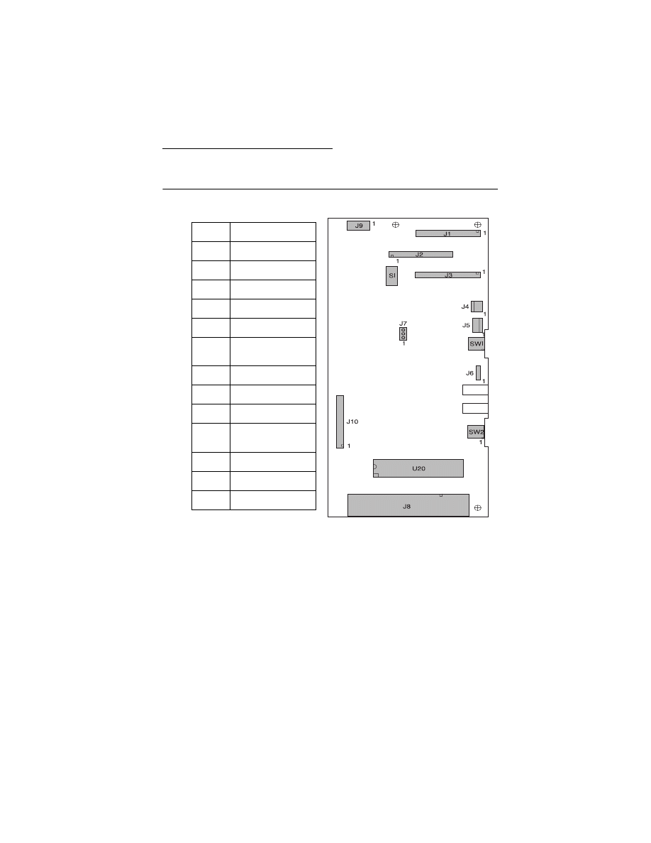
5. Connector Locations
System Board Connectors
J1
Printhead Cable 1
J2
Printhead Cable 2
J3
Printhead Cable 3
J4
Transport Motor
J5
Paper Feed Motor
J6
Test Jumper
J7
Temperature
Sensor
J8
Parallel Port
J9
Power Supply
J10
Video Board
SW1
Paper Feed
Switch
SW2
Power Switch
S1
EOF Sensor
U20
Code Module
Connector Locations 5-2
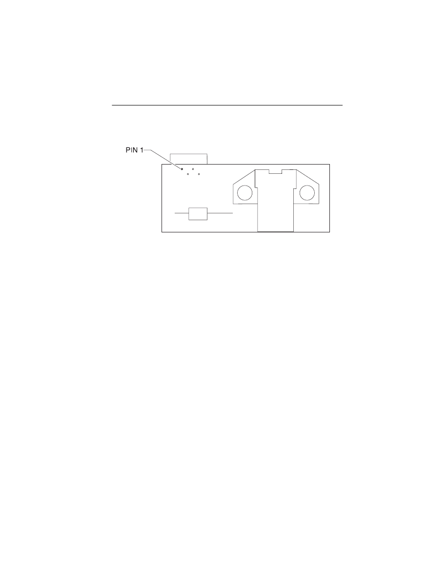
4092
Encoder Card Connector

Preventive Maintenance 6-1
4092
6. Preventive Maintenance
This chapter contains the lubrication specifications. Follow these
recommendations to prevent problems and maintain optimum
performance.
Lubrication Specifications
Lubricate only when parts are replaced or as needed, not on a
scheduled basis. Use grease P/N 1329301 to lubricate the following:
•
All gear mounting studs.
•
The left and right ends of the large feed roller at the side frames.
•
Both ends of the sheet feeder pick roll shaft at the side frames.
•
The carrier to carrier frame engagement.
•
The carrier guide rod, and carrier guide rod bearings.
•
Both ends of the exit roller shaft.

Preventive Maintenance 6-1
6. Preventive Maintenance
This chapter contains the lubrication specifications. Follow these
recommendations to prevent problems and maintain optimum
performance.
Lubrication Specifications
Lubricate only when parts are replaced or as needed, not on a
scheduled basis. Use grease P/N 99A0394 to lubricate the following:
•
All gear mounting studs.
•
The left and right ends of the large feed roller at the side frames.
•
Both ends of the sheet feeder pick roll shaft at the side frames.
•
The carrier to carrier frame engagement.
•
The carrier guide rod, and carrier guide rod bearings.
•
Both ends of the exit roller shaft.

Parts Catalog 7-1
4092
7. Parts Catalog
How To Use This Parts Catalog
•
SIMILAR ASSEMBLIES: If two assemblies contain a majority of
identical parts, they are broken down on the same list. Common
parts are shown by one index number. Parts peculiar to one or
the other of the assemblies are listed separately and identified
by description.
•
NS: (Not Shown) in the Asm-Index column indicates that the
part is procurable but is not pictured in the illustration.
•
PP: in the Description column indicates the part is available in
the listed parts packet.
7-2
4092
Assembly 1: Covers
Parts Catalog 7-3
4092
Asm-
Index
Part
Number
Units
Description
1 -1
17B0150
1
Base Asm includes Feet, Gutter Pad
(4092-001, 003, 006)
1
17B0151
1
Base Asm includes Feet, Gutter Pad
(4092-002, 004, 005)
1A
13A1234
1
Exit Tray and Extender
(4092-001, 003, 006)
1A
13A1452
1
Exit Tray and Extender
(4092-002, 004, 005)
2
13B0201
1
Front Cover Asm, Access Cover with
Door Latch, Buttons & LED Lens
(4092-001, 006)
2
13B0403
1
Front Cover Asm, Access Cover with
Door Latch, Buttons & LED Lens
(4092-002)
2
17B0152
1
Front Cover Asm, Access Cover with
Door Latch, Buttons & LED Lens
(4092-003)
2
17B0153
1
Front Cover Asm, Access Cover with
Door Latch, Buttons & LED Lens
(4092-004)
2
17B0165
1
Front Cover Asm, Access Cover with
Door Latch, Buttons & LED Lens
(4092-005)
2A
13B0202
1
Front Access Door with Latch
(4092-001, 006)
2A
13B0402
1
Front Access Door with Latch
(4092-002)
2A
17B0154
1
Front Access Door with Latch
(4092-003)
2A
17B0155
1
Front Access Door with Latch
(4092-004, 005)
3
69G4118
1
Rear Cover (4092-001, 003, 006)
3
13A1444
1
Rear Cover (4092-002, 004, 005)

7-4
4092
Assembly 1: Covers (continued)
Parts Catalog 7-5
4092
Asm-
Index
Part
Number
Units
Description
1 - 4
17B0158
1
Gutter Pad (Large)
4
69G4119
1
Gutter Pad (Small)
5
13B0203
1
Lens (LED) & Power Button
6
13B0239
2
Screw (PP)
7
13B0239
1
Screw (PP)
8
17B0166
1
Cover, Video Card
9
17B0164
1
Cable, Video Ground
10
17B0163
1
Cable, Video Flex
11
17B0161
1
Board, Video
NS
17B0162
1
Cable, Video (Coax)
NS
13A1257
1
Office Organizer
NS
7347806
1
Plain Package B/M includes:
(Carton, Cushion Set, Sealing Tape)
NS
13A3554
1
Garage with Sticker
(4092-003, 004)
NS
17B0159
1
“Need More Ink” Label
(4092-003, 004)
NS
17B0156
1
“Snappy” Sticker
NS
17B0167
1
Ex2 Inside Sticker
(4092-003, 004)
7-6
4092
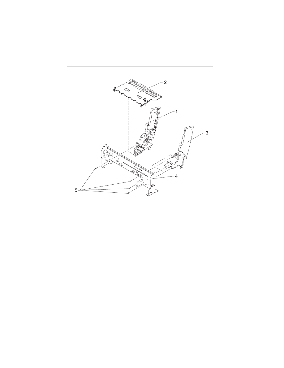
Assembly 2: Frames

Parts Catalog 7-7
4092
Asm-
Index
Part
Number
Units
Description
2 -1
13B0411
1
Left Side Frame
(4092-001, 003, 006)
1
13B0412
1
Left Side Frame
(4092-002, 004, 005)
2
13B0272
1
Mid Frame
3
13A1236
1
Right Side Frame
(4092-001, 003, 006)
3
13A1446
1
Right Side Frame
(4092-002, 004, 005)
4
13B0204
1
Carrier Frame
7-8
4092
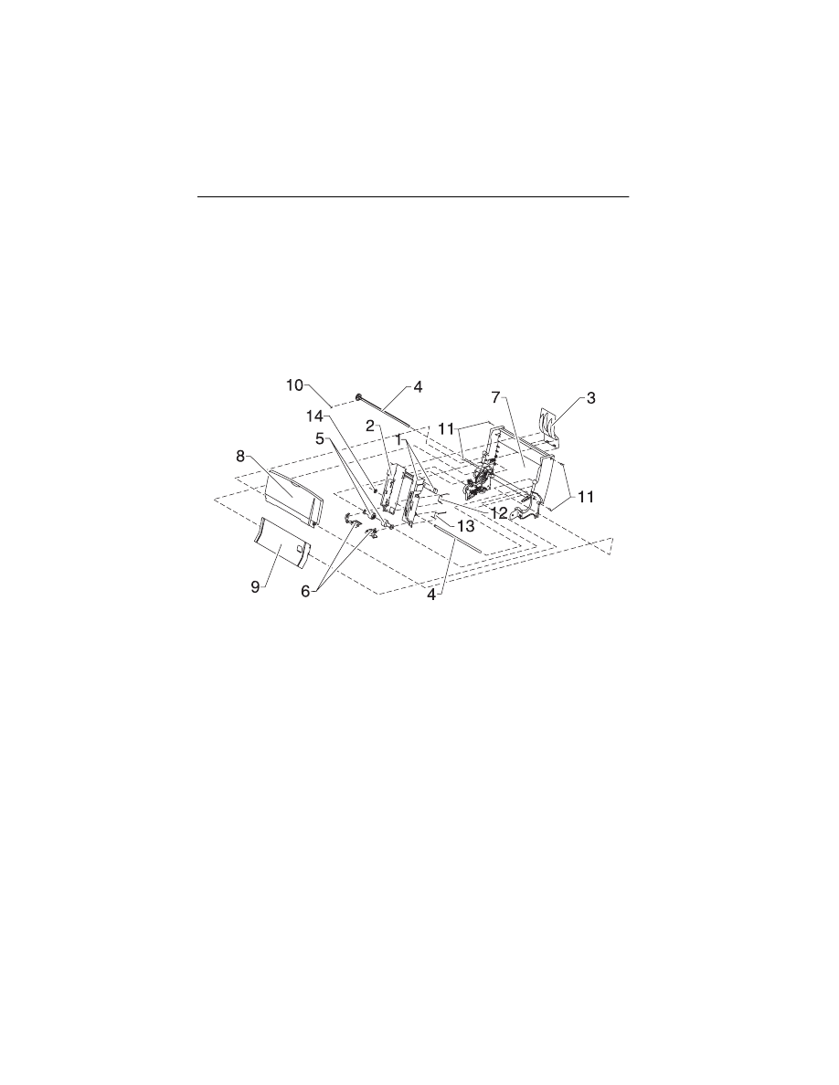
Assembly 3: Paper Feed
Parts Catalog 7-9
4092
Asm-
Index
Part
Number
Units
Description
3 -1
13B0205
1
Paper Guide Asm includes EOF
Flag & Spring
2
13A1280
1
Small Feed Roll Shaft Roll B/M
and Paper Flap
3
13B0212
1
Star Roller Asm
4
13B0275
1
Large Feed Roll Asm (includes
Small Compound Idler Gear)
5
13B0276
1
Paper Feed Motor, Motor Gear,
Toroid
5A
13B0239
1
Warning Label, Motor (PP)
6
13B0271
1
Gears B/M
7
69G4398
1
Feed Arm Asm
8
13B0239
1
C-Clip (PP)
9
13B0239
3
Spring, Small Feed Roll (PP)
10
13B0239
2
Screw, Paper Feed Motor
Mounting (PP)
11
13B0223
1
Exit Roller
12
70G0579
1
Exit Drive Belt
NS
13B0239
1
Gear Retainer (PP)
7-10
4092
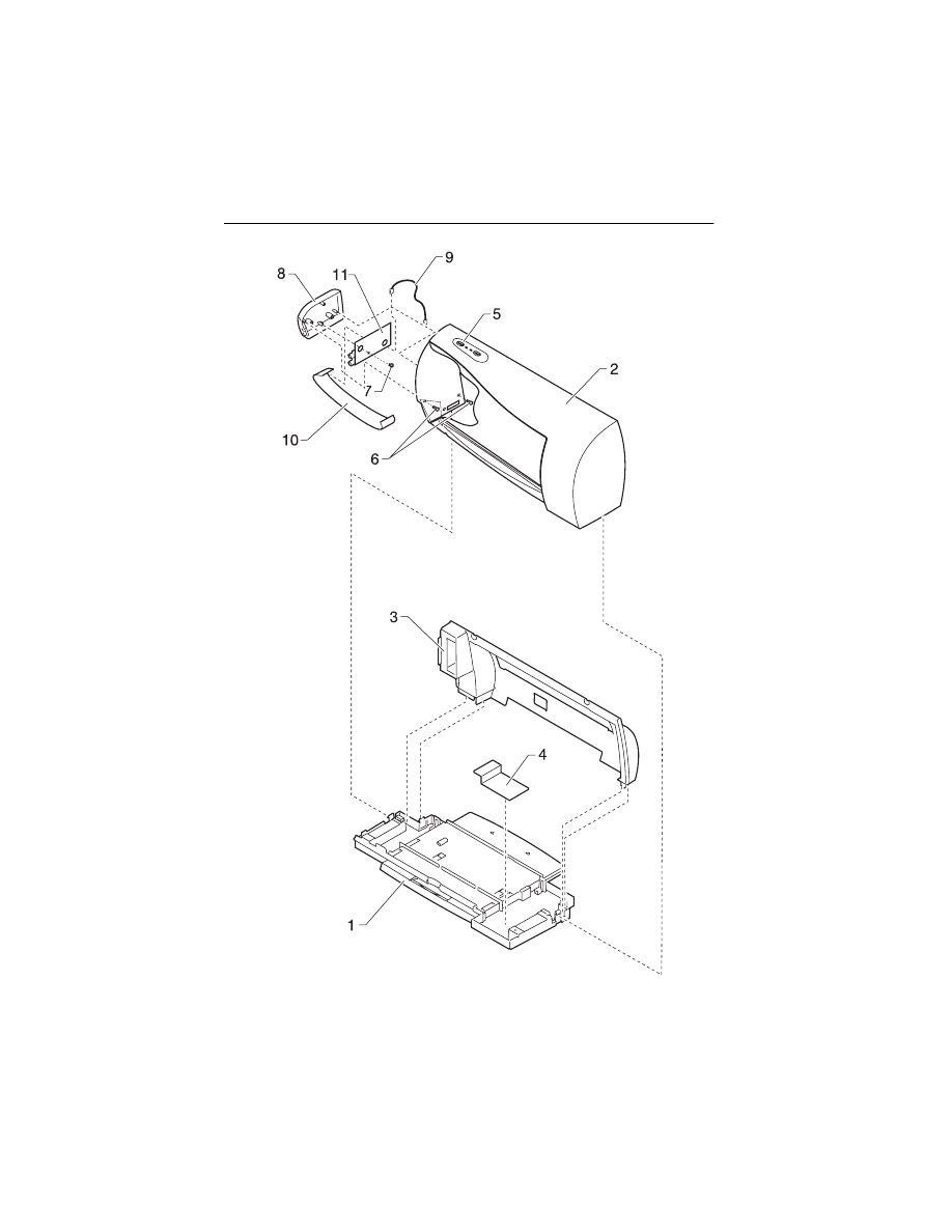
Assembly 4: Electronics
Parts Catalog 7-11
4092
Asm-
Index
Part
Number
Units
Description
4 -1
13B0070
1
System Board, W/O Code Module
1
17B0160
1
System Board, W/O Code Module
(4092-005)
2
13B0214
1
Power Supply (Universal) with
Ground Plane, Insulator, Cover
3
1339526
1342514
1339520
1339520
1342514
1342514
1342534
1339526
1342534
1342514
1342514
1339525
1342514
1339519
1342514
1339520
1339520
1339520
1342514
1342514
1339521
1339524
70G0496
1342514
1339520
1342514
1339520
1342514
1342536
1342514
1339517
1339523
1339520
1339520
1339522
1339519
1342536
1342514
1
Power Cord, U.S.
Power Cord, Argentina
Power Cord, Austria
Power Cord, Belgium
Power Cord, Bolivia
Power Cord, Brazil (LV)
Power Cord, Brazil (HV)
Power Cord, Canada
Power Cord, Chile
Power Cord, Columbia
Power Cord, Costa Rica
Power Cord, Denmark
Power Cord, Ecuador
Power Cord, Egypt
Power Cord, El Salvador
Power Cord, Finland
Power Cord, France
Power Cord, Germany
Power Cord, Guatemala
Power Cord, Honduras
Power Cord, Israel
Power Cord, Italy
Power Cord, Japan
Power Cord, Mexico
Power Cord, Netherlands
Power Cord, Nicaragua
Power Cord, Norway
Power Cord, Panama
Power Cord, Paraguay
Power Cord, Peru
Power Cord, Saudi Arabia
Power Cord, South Africa
Power Cord, Spain
Power Cord, Sweden
Power Cord, Switzerland
Power Cord, United Kingdom
Power Cord, Uruguay
Power Cord, Venezuela

7-12
4092
Assembly 4: Electronics (continued)
Parts Catalog 7-13
Asm-
Index
Part
Number
Units
Description
4-4
13B0309
1
Code Module
(4092-001, 002, 003, 004, 006)
4
17B0186
1
Code Module
(4092-005)
5
13B0239
5
Screw, System Board Mounting,
Frame Mounting (PP)
6
13B0045
1
Thermal Sensor Board w/ Cable
7
13B0239
1
Screw, Thermal Sensor Mounting
(PP)
NS
13B0239
1
Jumper, 2-Pin (PP)
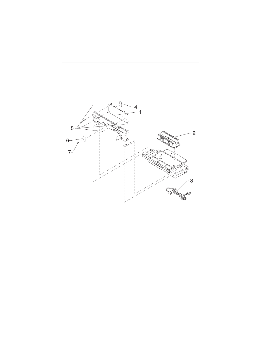
7-14
4092
Assembly 5: Carrier
Parts Catalog 7-15
4092
Asm-
Index
Part
Number
Units
Description
5 -1
13B0237
1
Printhead Carrier B/M
2
13B0222
1
Printhead Cable (Folded)
3
13B0238
1
Rubber Backer
4
13B0217
1
Carrier Guide Rod
5
69G4156
1
Encoder Card Asm
6
13B0239
1
Screw, Encoder Card Mounting
(PP)
7
13B0221
1
Printhead Cartridge Interlock Key
B/M
8
13B0239
2
Screw, Carrier Guide Rod (PP)
9
17B0168
2
Washer, Lock (Packet of 50)
7-16
4092
Assembly 6: Carrier Transport
Parts Catalog 7-17
4092
Asm-
Index
Part
Number
Units
Description
6 -1
13B0219
1
Carrier Transport Motor & Pulley
2
13B0215
1
Carrier Belt
3
69G4403
1
Encoder Strip
4
17B0157
1
Idler Pulley Tension Asm
5
13B0239
2
Screw, Carrier Transport Motor
Mounting (PP)
6
13B0239
1
Tensioner, Encoder Strip (PP)
7-18
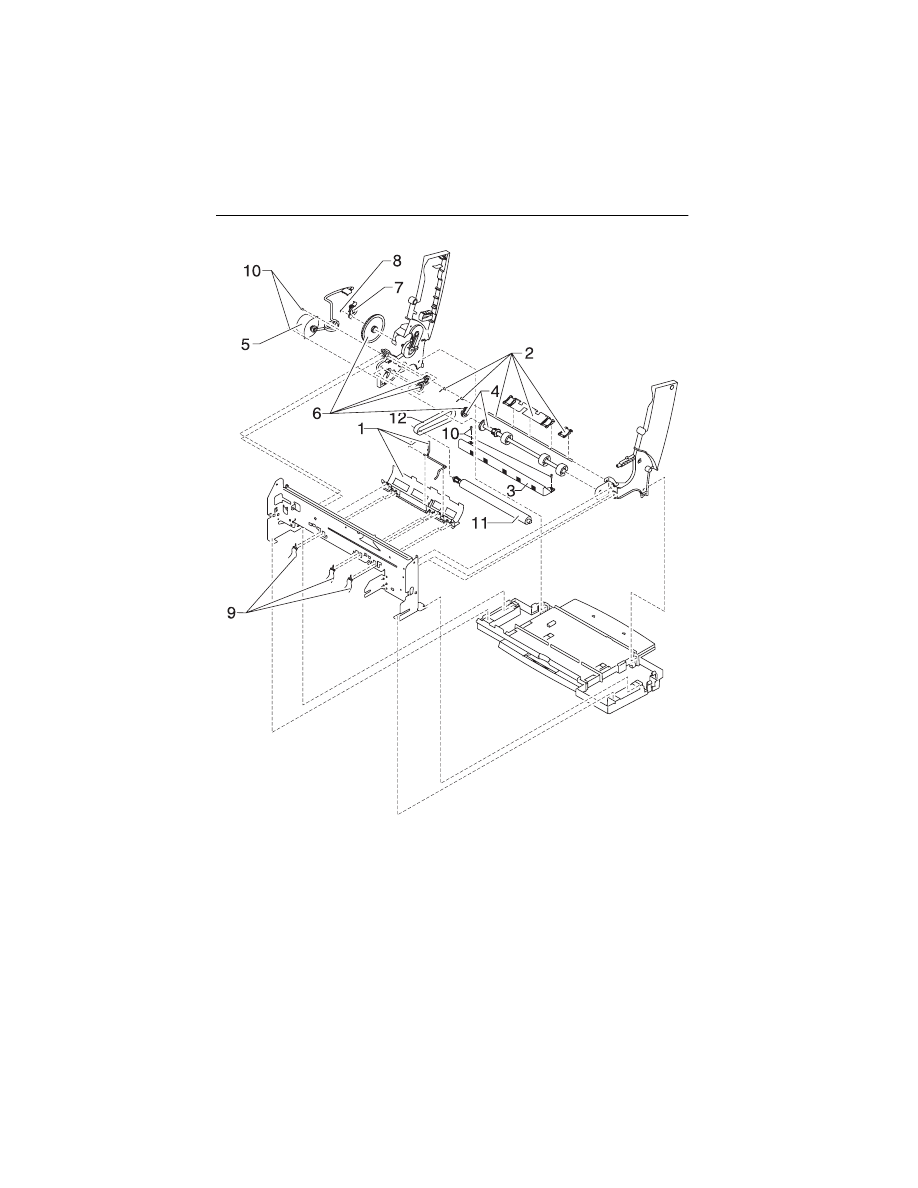
4092
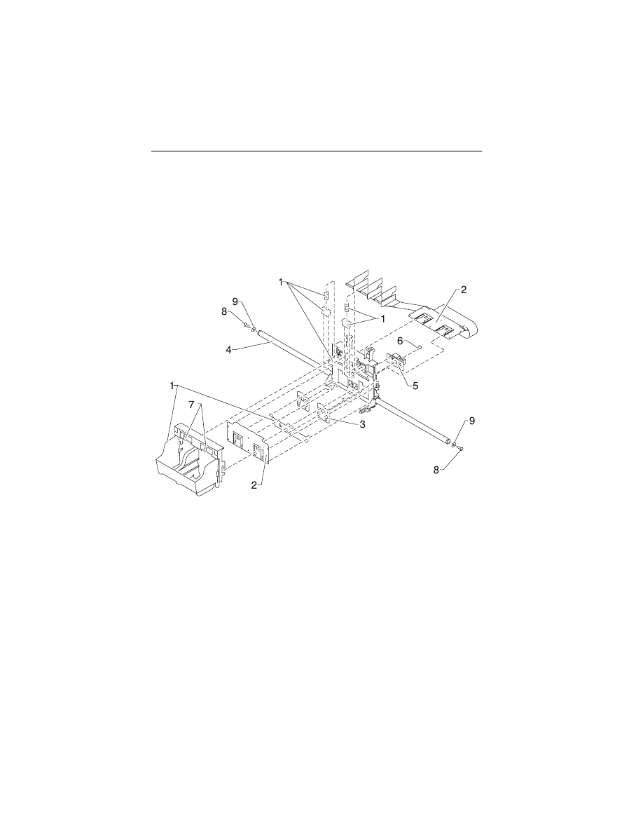
Assembly 7: Sheet Feeder
Parts Catalog 7-19
4092
Asm-
Index
Part
Number
Units
Description
7 -1
13A1227
1
Right Edge Guide & Width Adjust
Strip (4092-001, 003, 006)
1
13A1442
1
Right Edge Guide & Width Adjust
Strip (4092-002, 004, 005)
2
13A1228
1
Left Edge Guide
(4092-001, 003, 006)
2
13A1443
1
Left Edge Guide
(4092-002, 004, 005)
3
69G4131
1
Upper Paper Support
(4092-001, 003, 006)
3
13A1451
1
Upper Paper Support
(4092-002, 004, 005)
4
13A1229
1
Pick Roll & Paper Load Shaft B/M
5
1367463
2
Pick Roll Hub Asm
6
1367019
1
Envelope Buckler B/M, Left & Right
7
69G4169
1
Back Plate (4092-001, 003, 006)
7
13A1448
1
Back Plate (4092-002, 004, 005)
8
13A1226
1
Paper Load Door
(4092-001, 003, 006)
8
13A1440
1
Paper Load Door
(4092-002, 004, 005)
9
69G4165
1
Manual Insert Tray
(4092-001, 003, 006)
9
13A1447
1
Manual Insert Tray
(4092-002, 004, 005)
10
13B0239
1
E-Ring (PP)
11
13B0239
4
Screw, Side Frame (PP)
12
13B0239
1
Spring, Left Paper Load (PP)
13
13B0239
1
Spring, Right Paper Load (PP)
14
13B0271
1
Gear, Paper Load (Gears B/M)
7-20
4092
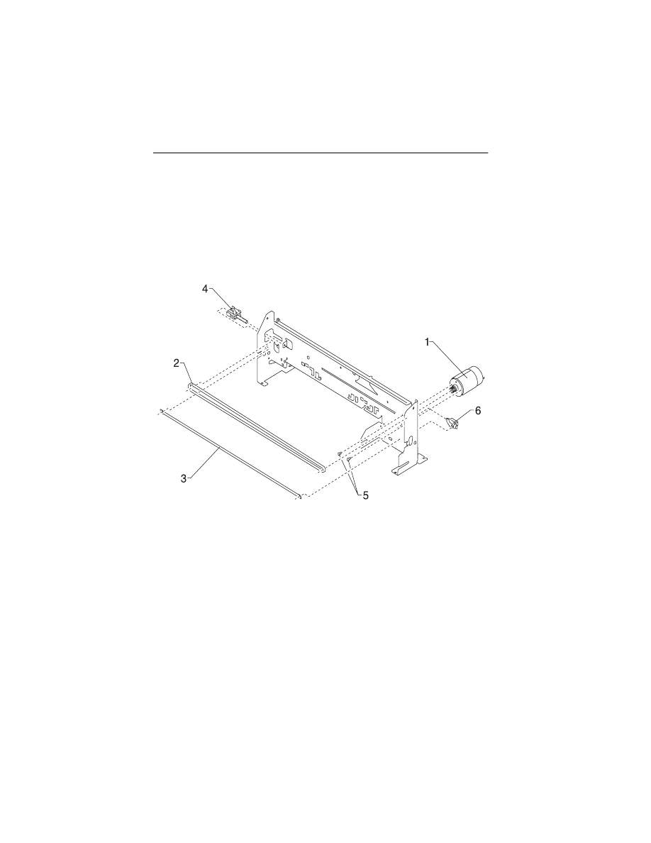
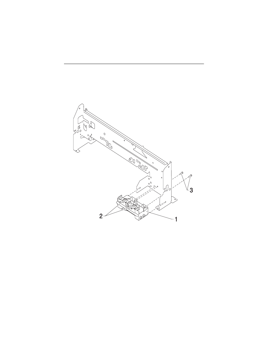
Assembly 8: Maintenance Station
Parts Catalog 7-21
4092
Asm-
Index
Part
number
Units
Description
8 -1
13B0160
1
Maintenance Station Asm
2
70G0590
1
Wiper and Cap B/M (one of each)
3
13B0239
2
Screw, Maintenance Station
Mounting (PP)

X-1
4092
Index
3
A
Abbreviations
Adjustments
Assemblies
1 Covers
2 Frames
3 Paper Feed
4 Electronics
5 Carrier
6 Carrier Transport
7 Sheet Feeder
8 Maintenance Station
C
Connector Locations
Connectors
Encoder Card
System Board
D
Diagnostic Aids
Diagnostic Information
E
Error Indicator Table
ESD-Sensitive Parts
G
General Information
L
Lubrication Specifications
M
Maintenance Approach
P
Parts Catalog
Plastic Latches
POST
Sequence
Symptom Table
Power Consumption
Preventive Maintenance
Problems
Carrier Transport
Communications
Maintenance Station
Operator Panel
Paper Feed
Power
Print Quality
R
Removal Procedures
Removals
Base Assembly
Carrier Belt
Carrier Frame
Carrier Transport Motor
Code Module
Edge Guide Asm
Encoder Card
Encoder Strip
Envelope Bucklers
EOF Flag Asm
Exit Drive Belt
Exit Roller
Feed Arm Assembly
Front Cover
Gutter Pad
Inside Idler Gears
Large Feed Roll
Large Outside Gear
Left Side Frame
Maintenance Caps
Maintenance Station
Maintenance Wipers
Manual Insert Tray
Mid Frame Assembly
Paper Deflector
Paper Feed Motor
Paper Flap
Paper Guide
Paper Load Door
Paper Load Shaft
Pick Roll Hub
Pick Roll Shaft
Power Supply
Printhead Cable
Printhead Carrier
Printhead Cradle
Printhead Rubber Backer
Rear Cover
Right Side Frame
Small Feed Roll Shaft
Small Feed Rollers
Star Roller
System Board

X-2
4092
Video Board
Repair Information
S
Service Checks
Envelope Feed
First Print Line
Maintenance Station
Paper Feed
Paper Path
Parallel Port
Power
Print Quality
Transport
Video
Start
Symptom Table (POST)
Symptom Tables
T
Tests
Encoder Sensor
Initialize Error Log
Parallel Port
Print NVRAM Contents
Test Page
Tools
Document Outline
- 1. General Information
- 2. Diagnostic Information
- 3. Diagnostic Aids
- 4. Repair Information
- Handling ESD-Sensitive Parts
- Adjustments
- Removal Procedures
- Releasing Plastic Latches
- Base Assembly Removal
- Carrier Belt Removal
- Carrier Frame Assembly Removal
- Carrier Transport Motor Removal
- Code Module Removal
- Edge Guide Asm and Paper Load Shaft Removal
- Encoder Card Removal
- Encoder Strip Removal
- Exit Drive Belt Removal
- Exit Roller Removal
- Feed Arm Assembly Removal
- Front Cover Removal
- Gutter Pad Removal
- Inside Idler Gears Removal
- Large Feed Roll Removal
- Large Outside Gear Removal
- Left Side Frame Assembly Removal
- Maintenance Station Assembly Removal
- Maintenance Wipers and Caps Removal
- Manual Insert Tray Removal
- Mid Frame Assembly Removal
- Paper Feed Motor Removal
- Paper Guide and EOF Flag Assembly Removal
- Paper Load Door Removal
- Pick Roll Shaft, Hub and Envelope Bucklers Removal
- Power Supply Removal
- Printhead Cable, Cradle & Paper Deflector Removal
- Printhead Carrier Assembly Removal
- Printhead Rubber Backer Removal
- Rear Cover Removal
- Right Side Frame Assembly Removal
- Small Feed Roll Shaft, Rollers & Paper Flap Removal
- Star Roller Removal
- System Board Removal
- Video Board Removal
- 5. Connector Locations
- 6. Preventive Maintenance
- 7. Parts Catalog
- Index
Wyszukiwarka
Podobne podstrony:
Lexmark Z 31 Color JetPrinter Service Manual
LEXMARK 2070 color jetprinter 4090 001 service manual
LEXMARK 030 color jetprinter 4091 001 service manual
Lexmark 3200 (4097) Color Jetprinter Service Manual
Lexmark 4078 00x Color JetPrinter 1020 Service Manual
Lexmark 4096 00x Color JetPrinter 1000, 1100 Service Manual
Epson Stylus Color 460 Service Manual
Lexmark Medley 4012 0XX Service Manual
Acer TFT LCD Color Monitor AL1713 Parts and Service
LEXMARK x83 x85 scan print copy 4403 xxx service manual
Epson Stylus Color 300 Service Manual
więcej podobnych podstron