ML15.241
MiniLine
24V, 0.63A, S
INGLE
P
HASE
I
NPUT
Dec. 2007 / Rev. 1.1 DS-ML15.241-EN
All parameters are specified at 24V, 0.63A, 230Vac, 25°C ambient and after a 5 minutes run-in time unless otherwise noted.
www.pulspower.com Phone +49 89 9278 0 Germany
1/20
P
OWER
S
UPPLY
■
100-240V Wide Range Input
■
NEC Class 2 Compliant
■
Adjustable Output Voltage
■
Efficiency up to 88.4%
■
Compact Design, Width only 22.5mm
■
Full Output Power Between -10°C and +60°C
■
Large International Approval Package
■
3 Year Warranty
1. G
ENERAL
D
ESCRIPTION
2. S
HORT
-
FORM
D
ATA
Output voltage
DC 24V
Adjustment range
24-28V
Output current
0.63–0.54A
24-28V
Output power
15W
Output ripple
< 50mVpp
20Hz to 20MHz
Input voltage
AC 100-240V
Wide Range Input
Mains frequency
50-60Hz
±6%
AC Input current
typ. 0.28 / 0.17A At 120 / 230Vac
Power factor
typ. 0.51 / 0.44
At 120 / 230Vac
AC Inrush current
16 / 31A
Typ. peak value
at 120 / 230Vac
40°C and cold start
DC Input
85-375Vdc
Efficiency
typ. 87.8 / 88.4% At 120 / 230Vac
Losses
typ. 2.1 / 2.0W
At 120 / 230Vac
Temperature range -10°C to +70°C
Operational
Derating
0.4W/°C
+60 to +70°C
Hold-up time
typ. 47 / 196ms
At 120 / 230Vac
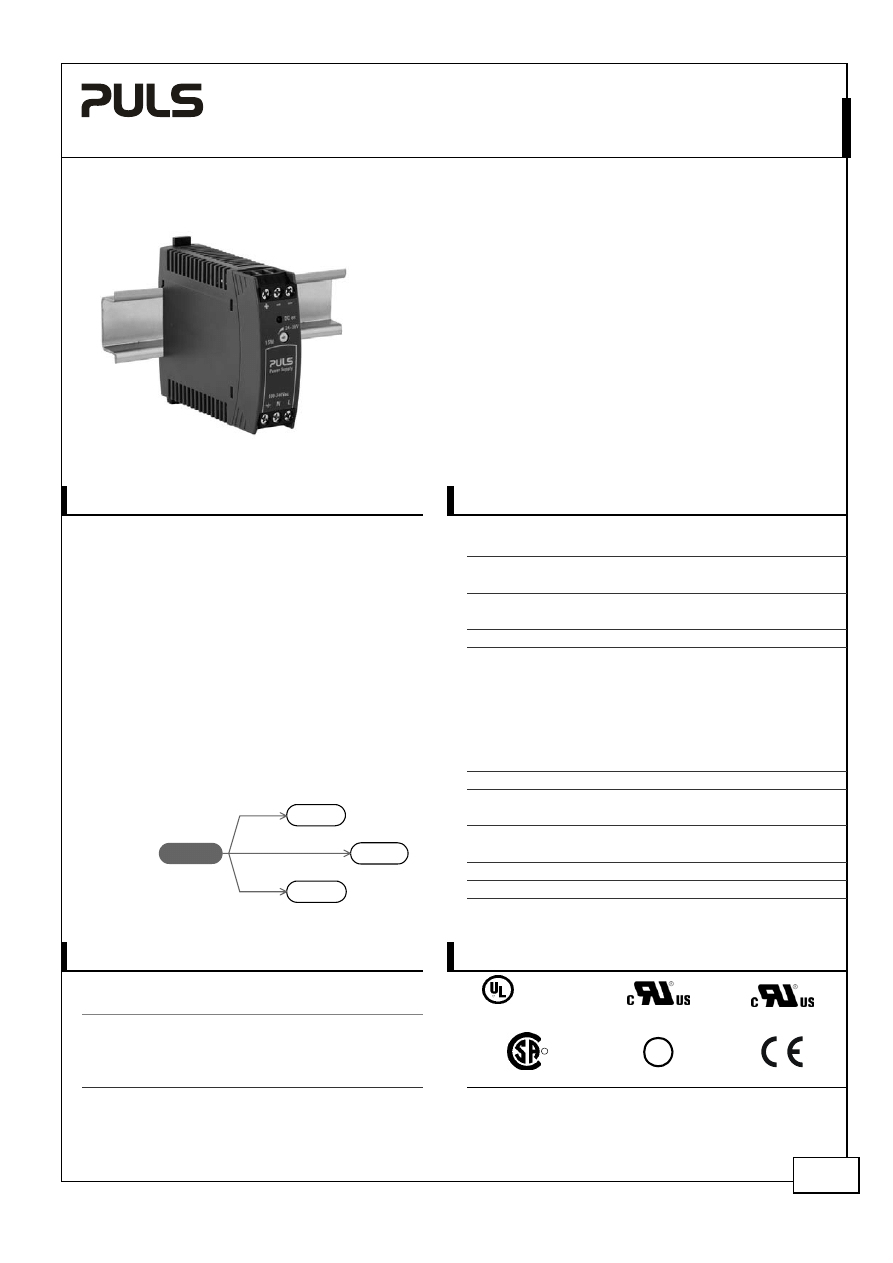
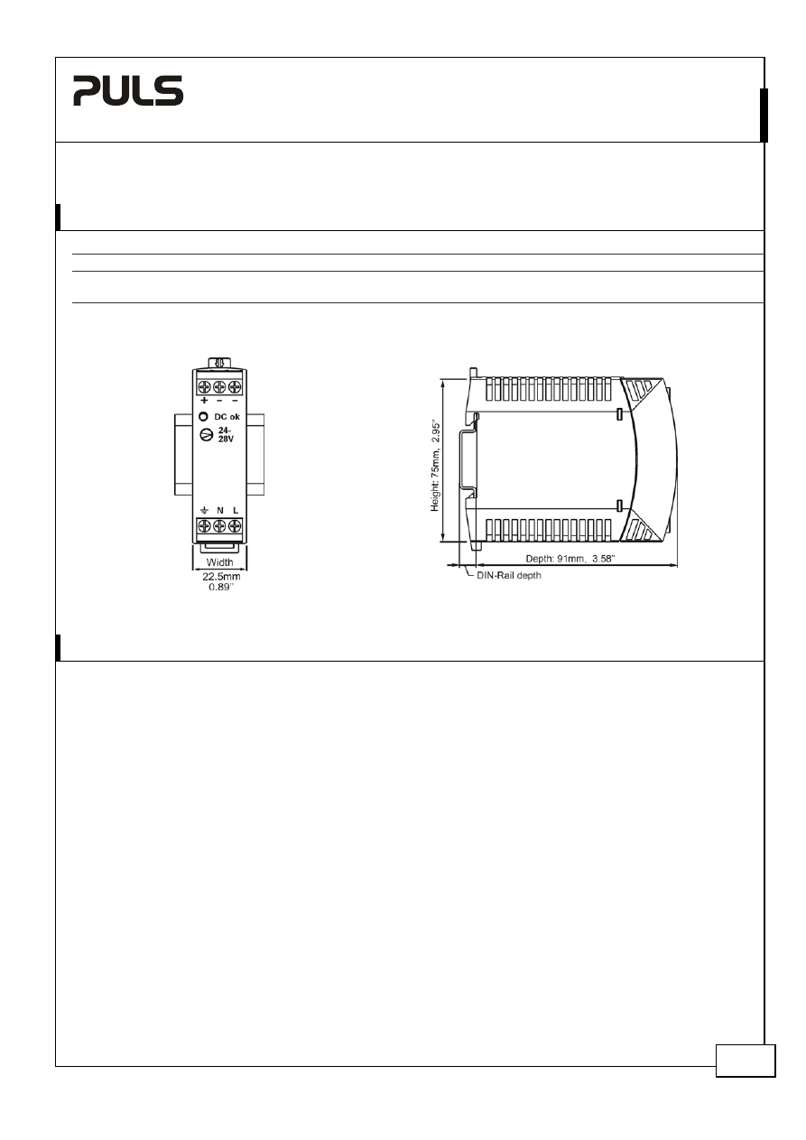
Dimensions 22.5x75x91mm
WxHxD
A compact size, light weight, simple mounting onto
the DIN-rail and the utilization of only quality
components are what makes the MiniLine power
supplies so easy to use and install within seconds.
A rugged electrical and mechanical design as well as
a high immunity against electrical disturbances on
the mains provides reliable output power. This offers
superior protection for equipment which is
connected to the public mains network or is exposed
to a critical industrial environment.
The MiniLine series offers output voltages from 5 to
56Vdc and a power rating from 15W to 100W.
The supplementary MiniLine decoupling diode
module MLY02.100 allows building of redundant
systems or to protect against back-feed voltages.
ML15.241
ML15.121
ML15.051
ML30.100
5V
Output
ML15
Related products
More
Power
12V
Output
24V Output
3. O
RDER
N
UMBERS
4. M
ARKINGS
Power
supply ML15.241
Standard unit
IND. CONT. EQ.
18WM
LISTED
UL 508
UL 60950-1
Class I Div 2
Accessory MLY02.100
Decoupling
/
Redundancy module
R
182790
C
US
GL
Marine
EMC, LVD
ML15.241
MiniLine
24V, 0.63A, S
INGLE
P
HASE
I
NPUT
Dec. 2007 / Rev. 1.1 DS-ML15.241-EN
All parameters are specified at 24V, 0.63A, 230Vac, 25°C ambient and after a 5 minutes run-in time unless otherwise noted.
www.pulspower.com Phone +49 89 9278 0 Germany
2/20
I
NDEX
P
AGE
I
NDEX
P
AGE
1.
General Description ............................................1
2.
Short-form Data ..................................................1
3.
Order Numbers....................................................1
4.
Markings ..............................................................1
5.
AC-Input...............................................................3
6.
Input Inrush Current Surge .................................4
7.
Hold-up Time.......................................................4
8.
DC-Input...............................................................5
9.
Output .................................................................6
10.
Efficiency and Power Losses................................7
11.
Functional Diagram.............................................8
12.
Reliability .............................................................8
13.
Front Side and User Elements.............................9
14.
Terminals and Wiring..........................................9
15.
EMC....................................................................10
16.
Environment ......................................................11
17.
Protection Features ...........................................11
18.
Safety .................................................................12
19.
Dielectric Strength ............................................12
20.
Approvals .......................................................... 13
21.
Fulfilled Standards............................................ 13
22.
Used Substances ............................................... 13
23.
Physical Dimensions and Weight ..................... 14
24.
Installation and Operation Instructions .......... 14
25.
Application Notes............................................. 15
25.1.
Peak Current Capability ......................... 15
25.2.
Back-feeding Loads ................................ 15
25.3.
Inductive and Capacitive Loads ............. 15
25.4.
Series Operation..................................... 16
25.5.
Parallel Use to Increase Output Power . 16
25.6.
Parallel Use for Redundancy.................. 17
25.7.
Charging of Batteries ............................. 17
25.8.
External Input Protection....................... 17
25.9.
Functional Earth Terminal ..................... 18
25.10.
Operation on Two Phases ...................... 18
25.11.
Use in a Tightly Sealed Enclosure .......... 19
25.12.
Mounting Orientations .......................... 20
I
NTENDED
U
SE
The power supply shall only be installed and put into operation by qualified personnel.
This power supply is designed for installation in an enclosure and is intended for the general use, such as in industrial
control, office, communication, and instrumentation equipment. Do not use this device in aircraft, trains and nuclear
equipment, where malfunctioning of the power supply may cause severe personal injury or threaten human life.
T
ERMINOLOGY AND
A
BREVIATIONS
PE and
symbol
PE is the abbreviation for Protective Earth and has the same meaning as the symbol
.
Earth, Ground
This document uses the term “earth” which is the same as the U.S. term “ground”.
T.b.d.
To be defined, value or description will follow later.
AC 230V
A figure displayed with the AC or DC before the value represents a nominal voltage with
standard tolerances (usually ±15%) included.
E.g.: DC 12V describes a 12V battery regardless whether it is charged (13.7V) or discharged
(10V). As long as not otherwise stated, AC 100V and AC 230V parameters are valid at 50Hz
and AC 120V parameters are valid at 60Hz mains frequency.
230Vac
A figure with the unit (Vac) at the end is a momentary figure without any additional
tolerances included.
D
ISCLAIMER
The information presented in this document is believed to be accurate and reliable and may change without notice.
The housing is patent by PULS (US patent No US D442,923S)
No part of this document may be reproduced or utilized in any form without permission in writing from the publisher.
ML15.241
MiniLine
24V, 0.63A, S
INGLE
P
HASE
I
NPUT
Dec. 2007 / Rev. 1.1 DS-ML15.241-EN
All parameters are specified at 24V, 0.63A, 230Vac, 25°C ambient and after a 5 minutes run-in time unless otherwise noted.
www.pulspower.com Phone +49 89 9278 0 Germany
3/20
5. AC-I
NPUT
AC
input
nom.
AC 100-240V
Wide-range input, TN-, TT-, IT-Mains, see Fig. 5-1
AC input range
85-264Vac Continuous
operation
264-300Vac <
0.5s
Input
frequency
nom.
50 – 60Hz
±6%
Turn-on
voltage
typ.
59Vac
Steady-state value, see Fig. 5-1
Shut-down
voltage
typ.
54Vac
Steady-state value, see Fig. 5-1
AC 100V
AC 120V
AC 230V
Input
current
(rms)
typ.
0.34A 0.28A 0.17A
At
24V, 0.63A see Fig. 5-3
Power
factor
*)
typ.
0.52 0.51 0.44
At
24V,
0.63A see Fig. 5-1
Crest factor **)
typ.
3.45 3.53 3.94
At
24V,
0.63A
Start-up
delay
typ.
700ms 700ms 700ms
See
Fig.
5-2
Rise
time
typ.
20ms
20ms
24ms
At 24V, 0.63A, see Fig. 5-2
Turn-on
overshoot
max.
100mV 100mV 100mV
See
Fig.
5-2
*)
The power factor is the ratio of the true (or real) power to the apparent power in an AC circuit.
**) The crest factor is the mathematical ratio of the peak value to RMS value of the input current waveform.
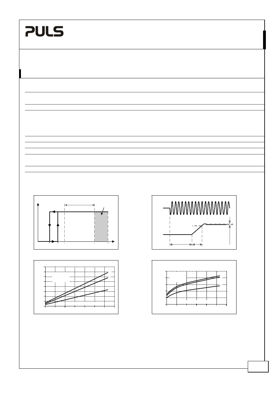
Fig. 5-1 Input voltage range
Fig. 5-2 Turn-on behavior, definitions
Tur
n
-on
85V
Rated
input range
max.
500ms
V
IN
P
OUT
54V
300Vac
264V
S
hut
-down
59V
Start-up
delay
Rise
Time
Ov
ershoot
- 5%
Output
Voltage
Intput
Voltage
Fig. 5-3 Input current vs. output load
Fig. 5-4 Power Factor vs. output load
0.7A
0.1
0.2
0.4
0
0
0.10
0.4A
Input Current, typ.
0.5
0.20
0.3
0.6
0.25
0.15
0.05
0.30
0.35
b
c
a
a) 100Vac
b) 120Vac
c) 230Vac
Output Current
0.7A
0.1
0.2
0.3
0.5
0.30
0.35
0.40
0.45
0.50
0.55
Power Factor, typ.
a) 100Vac
b) 120Vac
c) 230Vac
b
c
a
0.4
0.6
Output Current
ML15.241
MiniLine
24V, 0.63A, S
INGLE
P
HASE
I
NPUT
Dec. 2007 / Rev. 1.1 DS-ML15.241-EN
All parameters are specified at 24V, 0.63A, 230Vac, 25°C ambient and after a 5 minutes run-in time unless otherwise noted.
www.pulspower.com Phone +49 89 9278 0 Germany
4/20
6. I
NPUT
I
NRUSH
C
URRENT
S
URGE
A NTC limits the input inrush current after turn-on of the input voltage. The inrush current is input voltage and
ambient temperature dependent.
AC 100V
AC 120V
AC 230V
Inrush
current
max.
13A
peak
16A
peak
31A
peak
40°C ambient, cold start
typ.
11A
peak
13A
peak
26A
peak
40°C ambient, cold start
Inrush
energy
typ.
0.1A
2
s 0.1A
2
s 0.4A
2
s
40°C ambient, cold start
Fig. 6-1 Input inrush current, typical behavior
Fig. 6-2 Input inrush current, zoom into the first peak
Input Voltage
Input Current
Input Current
Input:
230Vac
Output:
24V, 0.63A
Ambient:
25°C
Upper curve:
Input current 5A / DIV
Lower curve:
Input voltage 500V / DIV
Time scale:
10ms / DIV
Input:
230Vac
Output:
24V, 0.63A
Ambient: 25°C
Input current curve: 5A / DIV, 500µs / DIV
Ipeak 23A
The charging current into EMI suppression capacitors is
disregarded in the first microseconds after switch-on.
7. H
OLD
-
UP
T
IME
AC 100V
AC 120V
AC 230V
Hold-up Time
typ.
64ms
98ms
375ms
0.315A, 24V, see
Fig. 7-1
typ.
31ms
47ms
196ms
0.63A, 24V, see
Fig. 7-1
Fig. 7-1 Hold-up time vs. input voltage
Fig. 7-2 Shut-down behavior, definitions
0
25
50
125
150ms
85
120
155
190
230Vac
Input Voltage
Hold-up Time
75
100
a) 24V 0.32A typ.
b) 24V 0.32Amin.
c) 24V 0.63A typ.
d) 24V 0.63A min.
a
b
c
d
- 5%
Hold-up Time
Zero Transition
Output
Voltage
Intput
Voltage
Note: At no load, the hold-up time can be up to several seconds. The green DC-ok lamp is also on during this time.
ML15.241
MiniLine
24V, 0.63A, S
INGLE
P
HASE
I
NPUT
Dec. 2007 / Rev. 1.1 DS-ML15.241-EN
All parameters are specified at 24V, 0.63A, 230Vac, 25°C ambient and after a 5 minutes run-in time unless otherwise noted.
www.pulspower.com Phone +49 89 9278 0 Germany
5/20
8. DC-I
NPUT
DC input
nom.
DC 110-290V -25%/+30%
DC input range
min.
85-375Vdc
Continuous operation
DC input current
typ.
0.16A / 0.057A
110Vdc / 300Vdc, at 24V and 0.63A
Turn-on voltage
typ.
80Vdc
Steady state value
Shut-down voltage
typ.
60Vdc
Steady state value
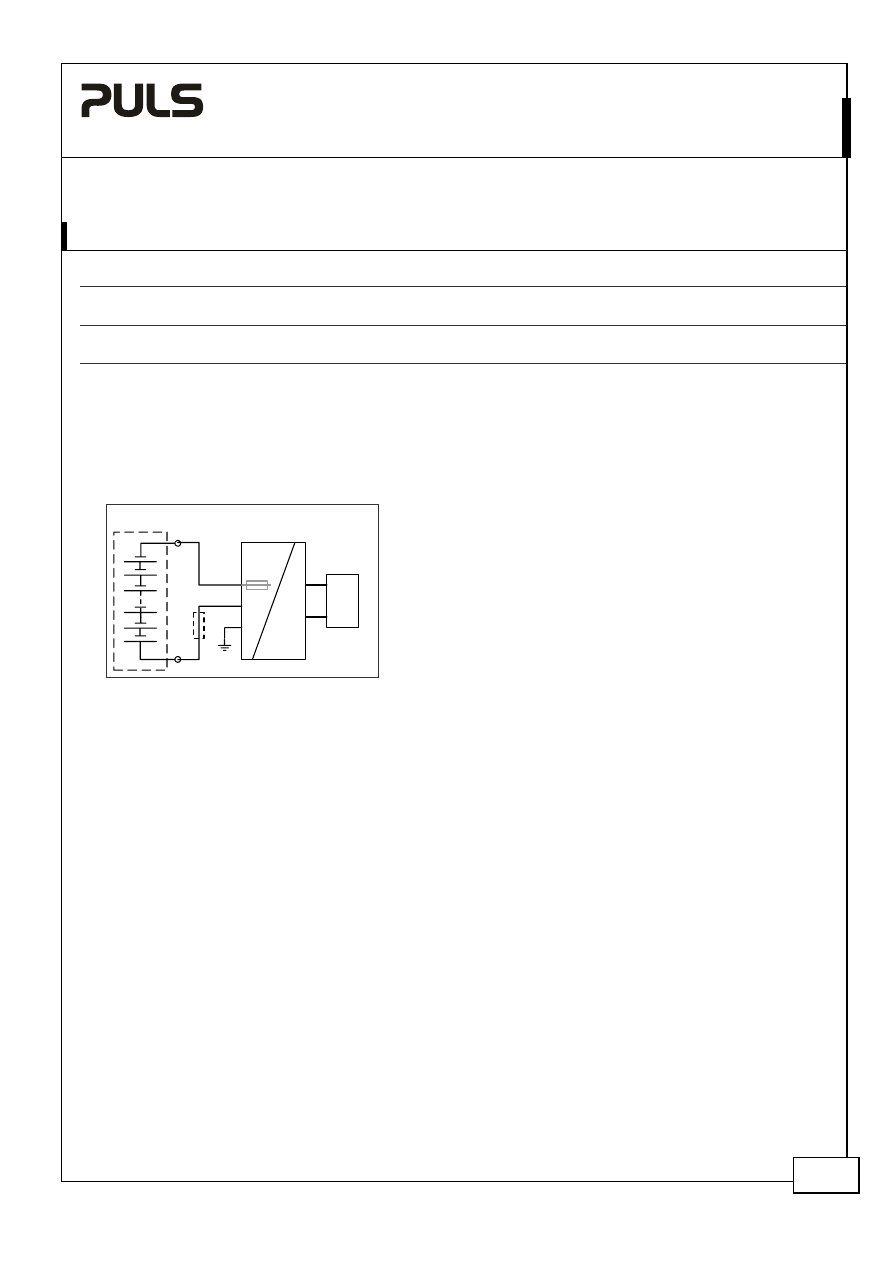
Instructions for DC use:
a)
Use a battery or similar DC source.
b)
Connect +pole to L and – pole to N.
c)
In case the – pole of the battery is not connected to earth, use an appropriate fuse to protect the N terminal.
Fig. 8-1 Wiring for DC Input
Fu
se
+
-
Load
L
N
FE
+
-
Power Supply
AC
DC
Battery
internal
fused
ML15.241
MiniLine
24V, 0.63A, S
INGLE
P
HASE
I
NPUT
Dec. 2007 / Rev. 1.1 DS-ML15.241-EN
All parameters are specified at 24V, 0.63A, 230Vac, 25°C ambient and after a 5 minutes run-in time unless otherwise noted.
www.pulspower.com Phone +49 89 9278 0 Germany
6/20
9. O
UTPUT
Output
voltage
nom.
24V
Adjustment
range
min.
24-28V Guaranteed
max.
30V
At clockwise end position of potentiometer
Factory
setting
24.5V
±0.2%,
at full load, cold unit
Line
regulation
max.
10mV
85 to 264Vac
Load
regulation
max.
100mV
Static value, 0A Æ 0.63A Æ 0A
Ripple and noise voltage
max.
50mVpp
20Hz to 20MHz, 50Ohm
Output
capacitance
typ.
900µF
Output current
nom.
0.63A
At 24V, see Fig. 9-1 for typical figures
nom.
0.54A
At 28V, see Fig. 9-1 for typical figures
Output
power
nom.
15W
Short-circuit
current
min.
Hiccup mode See Fig. 9-2
max.
Hiccup mode See Fig. 9-2
Fig. 9-1 Output voltage vs. output current, typ.
Fig. 9-2 Hiccup mode, Output current at
shorted output, 230V typ.
Output Voltage
0
0
4
8
12
28V
16
20
24
0.8A
0.5
0.3
0.1
0.7
0.4
0.2
0.6
Adjustment
Range
Output Current
Continuous
Hiccup Mode
Output
Current
0
2A
100
ms
t
250ms
250ms
Peak current capability (up to several ms)
The power supply can deliver a peak current which is higher than the specified short term current. This helps to start
current demanding loads or to safely operate subsequent circuit breakers.
The extra current is supplied by the output capacitors inside the power supply. During this event, the capacitors will
be discharged and cause a voltage dip on the output. Detailed curves can be found in chapter 25.1
Peak current voltage dips
typ.
from 24V to 15.5V
At 1.3A for 50ms, resistive load
typ.
from 24V to 17.5V
At 3.15A for 2ms, resistive load
typ.
from 24V to 11.5V
At 3.15A for 5ms, resistive load
ML15.241
MiniLine
24V, 0.63A, S
INGLE
P
HASE
I
NPUT
Dec. 2007 / Rev. 1.1 DS-ML15.241-EN
All parameters are specified at 24V, 0.63A, 230Vac, 25°C ambient and after a 5 minutes run-in time unless otherwise noted.
www.pulspower.com Phone +49 89 9278 0 Germany
7/20
10. E
FFICIENCY AND
P
OWER
L
OSSES
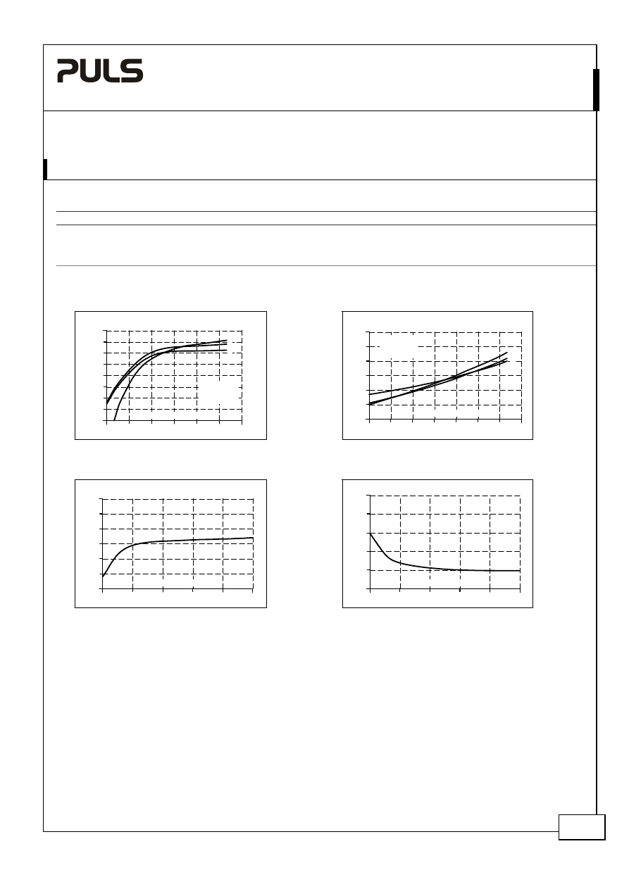
AC 100V
AC 120V
AC 230V
Efficiency
typ.
86.8%
87.8%
88.9%
0.63A, 24V (full load)
Power losses
typ.
0.5W
0.55W
0.85W
At no load
typ. 1.25W 1.17W 1.38W
0.315A, 24V (half load)
typ.
2.3W
2.1W
2.0W
0.63A, 24V (full load)
Fig. 10-1 Efficiency vs. output current at 24V
Fig. 10-2 Losses vs. output current at 24V
Efficiency
0.1
76
78
80
82
84
86
88
74
90%
0.7A
0.3
0.4
0.6
Output Current
0.2
0.5
a) 100Vac
b) 120Vac
c) 230Vac
b
c
a
Power Losses
0
0.1
0.7A
0
0.5
1.5
2.0
3W
2.5
0.2
0.3
0.4
Output Current
0.5
0.6
a) 100Vac
b) 120Vac
c) 230Vac
b
c
a
1.0
Fig. 10-3 Efficiency vs. input voltage at 24V
and 0.63A
Fig. 10-4 Losses vs. input voltage at 24V and
0.63A
Efficiency
85
120
155
190
225 260
Vac
85
86
87
88
89
90
91%
Input Voltage
Power Losses
1.75
2.25
2.50
2.75
3W
85
120
155
190
225 260
Vac
Input Voltage
2.00
ML15.241
MiniLine
24V, 0.63A, S
INGLE
P
HASE
I
NPUT
Dec. 2007 / Rev. 1.1 DS-ML15.241-EN
All parameters are specified at 24V, 0.63A, 230Vac, 25°C ambient and after a 5 minutes run-in time unless otherwise noted.
www.pulspower.com Phone +49 89 9278 0 Germany
8/20
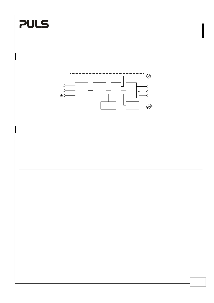
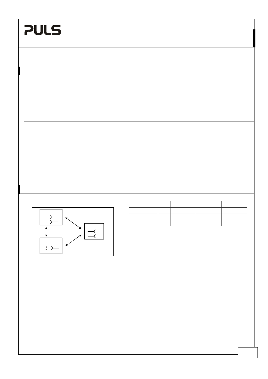
11. F
UNCTIONAL
D
IAGRAM
Fig. 11-1 Functional diagram
Input Fuse
&
Input Filter
L
N
Output Over-
Voltage
Protection
Input
Rectifier
&
Inrush
Limiter
Power
Converter
Output
Voltage
Regulator
+
-
-
Output
Filter
V
OUT
DC
on
12. R
ELIABILITY
These units are extremely reliable and use only the highest quality materials. The number of critical components such
as electrolytic capacitors has been reduced.
AC 100V
AC 120V
AC 230V
Lifetime expectancy
min.
197 000h
200 000h
196 000h
40°C, 24V, 0.63A
min.
> 15 years
> 15 years
> 15 years
40°C, 24V, 0.315A
min.
> 15 years
> 15 years
> 15 years
25°C, 24V, 0.63A
MTBF SN 29500, IEC 61709
4 016 000h
4 360 000h
4 369 000h
40°C, 24V, 0.63A
6 586 000h
7 150 000h
7 165 000h
25°C, 24V, 0.63A
MTBF MIL HDBK 217F
1 112 000h
1 169 000h
1 095 000h
40°C, 24V, 0.63A, Ground Benign GB40
1 490 000h
1 566 000h
1 467 000h
25°C, 24V, 0.63A, Ground Benign GB25
The Lifetime expectancy shown in the table indicates the operating hours (service life) and is determined by the
lifetime expectancy of the built-in electrolytic capacitors.
Lifetime expectancy is specified in operational hours. Lifetime expectancy is calculated according to the capacitor’s
manufacturer specification. The prediction model allows a calculation of up to 15 years from date of shipment.
MTBF stands for Mean Time Between Failure, which is calculated according to statistical device failures, and indicates
reliability of a device. It is the statistical representation of the likelihood of a unit to fail and does not necessarily
represent the life of a product.
ML15.241
MiniLine
24V, 0.63A, S
INGLE
P
HASE
I
NPUT
Dec. 2007 / Rev. 1.1 DS-ML15.241-EN
All parameters are specified at 24V, 0.63A, 230Vac, 25°C ambient and after a 5 minutes run-in time unless otherwise noted.
www.pulspower.com Phone +49 89 9278 0 Germany
9/20
13. F
RONT
S
IDE AND
U
SER
E
LEMENTS
Fig. 13-1 Front side
A Output
Terminals
Screw terminals
Dual terminals for the negative pole allows an easy earthing of the output
voltage
+
Positive output
-
Negative (return) output
B Input
Terminals
Screw terminals
L Neutral
input
N Line
(hot)
input
EMI
ground
Ground this terminal to minimize high-frequency emissions.
For safety reasons, connecting to ground is not required.
C DC-ON
LED
(green)
On when the voltage is > 19V
D Output voltage potentiometer
Turn to set the output voltage. Factory setting is 24.5V.
14. T
ERMINALS AND
W
IRING
All terminals are easy to access when mounted on the panel. Input and output terminals are separated from each
other (input below, output above) to help in error-free wiring.
Type
Screw
terminals
Solid
wire
0.5-6mm
2
Stranded
wire
0.5-4mm
2
American wire gauge
20-10 AWG
Ferrules
Allowed, but not required
Recommended tightening torque
1Nm, 9lb.in
Screwdriver
3.5mm
slotted or Pozidrive No 2
Wire stripping length
7mm / 0.275inch
Instructions:
a)
Use appropriate copper cables that are designed for an operating temperatures of 60°C (for ambient up to 45°C)
and 75°C (for ambient up to 60°C), minimum.
b)
Ferrules are allowed, but not required.
c)
Follow local and national installation codes and regulations!
d)
Ensure that all strands of a stranded wire enter the terminal connection!
e)
In order to fulfill GL requirements, unused terminal spaces must be closed.
ML15.241
MiniLine
24V, 0.63A, S
INGLE
P
HASE
I
NPUT
Dec. 2007 / Rev. 1.1 DS-ML15.241-EN
All parameters are specified at 24V, 0.63A, 230Vac, 25°C ambient and after a 5 minutes run-in time unless otherwise noted.
www.pulspower.com Phone +49 89 9278 0 Germany
10/20
15. EMC
The CE mark indicates conformance with EMC directive 89/336/EC, 93/68/EC and 2004/108/EC and the low-voltage
directive (LVD) 73/23/EC, 93/68/EC, 2006/95/EC. A detailed EMC Report is available on request.
All results and investigation were performed with functional earth wire.
EMC Immunity
EN 61000-6-2, EN 61000-6-1
Generic standards
Electrostatic discharge
EN 61000-4-2
Contact discharge
Air discharge
8kV
8kV
Criterion A
Criterion A
Electromagnetic RF field
EN 61000-4-3 80MHz-2.7GHz
10V/m
Criterion
A
Fast transients (Burst)
EN 61000-4-4
Input lines
Output lines
4kV
2kV
Criterion A
Criterion A
Surge voltage on input
EN 61000-4-5
L Æ N
N / L Æ PE
2kV
4kV
Criterion A
Criterion A
Surge voltage on output
EN 61000-4-5
+ Æ -
+ / - Æ PE
500V
500V
Criterion A
Criterion A
Conducted disturbance
EN 61000-4-6
0,15-80MHz
10V
Criterion A
Mains voltage dips
EN 61000-4-11
0% of 100Vac
40% of 100Vac
70% of 100Vac
0% of 200Vac
40% of 200Vac
70% of 200Vac
0Vac, 20ms
40Vac, 200ms
70Vac, 500ms
0Vac, 20ms
80Vac, 200ms
140Vac, 500ms
Criterion A
Criterion C
Criterion A
Criterion A
Criterion A
Criterion A
Voltage interruptions
EN 61000-4-11
0Vac, 5000ms
Criterion C
Input voltage swells
PULS internal standard
300Vac, 500ms
Criterion A
Powerful transients
VDE 0160
Over entire load
range
750V, 1.3ms
Criterion A
Criterions:
A: Power supply shows normal operation behavior within the defined limits.
C: Temporary loss of function is possible. Power supply might shut-down and restarts by itself. No damages or hazards to the power
supply will occur.
EMC Emission
EN 61000-6-3, EN 61000-6-4
Generic standards
Conducted emission
EN 55011, EN 55022, FCC Part 15, CISPR 11, CISPR 22
Class B, input lines
EN 55022
Class B, output lines
Radiated emission
EN 55011, EN 55022
Class B
Harmonic input current
EN 61000-3-2
Not applicable
(below 75W input power)
Voltage fluctuations, flicker EN
61000-3-3
Fulfilled
This device complies with FCC Part 15 rules.
Operation is subjected to the following two conditions: (1) this device may not cause harmful interference, and (2) this
device must accept any interference received, including interference that may cause undesired operation.
Switching frequency
constant, typ. 65kHz
ML15.241
MiniLine
24V, 0.63A, S
INGLE
P
HASE
I
NPUT
Dec. 2007 / Rev. 1.1 DS-ML15.241-EN
All parameters are specified at 24V, 0.63A, 230Vac, 25°C ambient and after a 5 minutes run-in time unless otherwise noted.
www.pulspower.com Phone +49 89 9278 0 Germany
11/20
16. E
NVIRONMENT
Operational temperature
-10°C to +70°C (14°F to 158°F)
Reduce output power acc. to Fig. 16-1
Output de-rating
0.4W/°C
60-70°C (140°F to 158°F), see Fig. 16-1
Storage temperature
-40 to +85°C (-40°F to 185°F)
Storage and transportation
Humidity
5 to 95% r.H.
IEC 60068-2-30
Do not energize while condensation is present
Vibration sinusoidal
2-17.8Hz: ±1.6mm; 17.8-500Hz: 2g
2 hours / axis
IEC 60068-2-6
Shock
15g 6ms, 10g 11ms
3 bumps / direction, 18 bumps in total
IEC 60068-2-27
Altitude
0 to 6000m (0 to 20000ft)
Reduce output power or ambient
temperature above 2000m sea level.
Output de-rating (for altitude)
1W/1000m or 5°C/1000m
Above 2000m (6500ft), see Fig. 16-2
Over-voltage category
III
EN 50178, IEC 62103, up to 2000m
II
Altitudes from 2000m to 6000m
Degree of pollution
2
EN 50178, IEC 62103, non conductive
Fig. 16-1 Output power vs. ambient temperature
Fig. 16-2 Output power vs. altitude
0
-10
0
20
40
70°C
2.5
5.0
7.5
10.0
12.5
15W
60
Ambient Temperature
Allowable
Output Power
0
0
2000
4000
6000m
2.5
5.0
7.5
10.0
12.5
15W
Altitude
A... Tamb < 60°C
B... Tamb < 50°C
C... Tamb < 40°C
A
B
C
Allowable
Output Power
The ambient temperature is defined 2cm below the unit.
17. P
ROTECTION
F
EATURES
Output
protection
Electronically protected against overload, no-load and short-circuits
Output over-voltage protection
Typ. 34V, max. 37V
In case of an internal power supply fault, a redundant
circuit limits the maximum output voltage. In such a
case, the output shuts down and stays down until the
input voltage is turned off and on again
Output over-current protection
Electronically limited
See Fig. 9-1
Degree of protection
IP 20
EN/IEC 60529
Penetration protection
> 2.5mm in diameter
E.g. screws, small parts
Over-temperature protection
Not included
Input transient protection
MOV
Metal Oxide Varistor
Internal
input
fuse
T3.15A H.B.C.
Not user replaceable
Note: In case of a over-voltage, overload, no-load or short-circuit event, an audible noise may be heard.
ML15.241
MiniLine
24V, 0.63A, S
INGLE
P
HASE
I
NPUT
Dec. 2007 / Rev. 1.1 DS-ML15.241-EN
All parameters are specified at 24V, 0.63A, 230Vac, 25°C ambient and after a 5 minutes run-in time unless otherwise noted.
www.pulspower.com Phone +49 89 9278 0 Germany
12/20
18. S
AFETY
Input / output separation
SELV
IEC/EN 60950-1
PELV
EN 60204-1, EN 50178, IEC 60364-4-41, IEC 62103
double or reinforced insulation
Class of protection
II
An earth connection is not required for safety reasons
but recommended to achieve highest EMI immunity.
See chapter 25.9 for details.
Isolation resistance
> 5MOhm
Input to output, 500Vdc
Touch current (leakage current)
typ. 0.17mA
1)
/ 5µA
2)
100Vac, 50Hz, TN mains
typ. 0.24mA
1)
/ 7µA
2)
120Vac, 60Hz, TN mains
typ. 0.40mA
1)
/ 8µA
2)
230Vac, 50Hz, TN mains
< 0.21mA
1)
/ 6µA
2)
110Vac, 50Hz, TN mains
< 0.30mA
1)
/ 7µA
2)
132Vac, 60Hz, TN mains
< 0.54mA
1)
/ 9µA
2)
264Vac, 50Hz, TN mains
1) Functional earth terminal connected to Protective earth
2) Functional earth terminal not connected
19. D
IELECTRIC
S
TRENGTH
Fig. 19-1 Dielectric strength
A B C
Type test
60s
2500Vac
3000Vac
500Vac
Factory test
5s
2500Vac
2500Vac
500Vac
Field test
5s
2000Vac
2000Vac
500Vac
A
C
N
L
Input
EMI Ground
Output
-
+
B
Type tests and factory tests:
Conducted by the manufacturer. Do not repeat test in field!
Rules for field test:
Use appropriate test equipment which applies the voltage
with a slow ramp! Connect L and N together as well as all
output poles.
The output voltage is floating and has no ohmic connection to ground.
To fulfill the PELV requirements according to EN60204-1 § 6.4.1, it is recommended that either the + pole, the – pole
or any other part of the output circuit should be connected to the protective earth system. This helps to avoid
situations in which a load starts unexpectedly or can not be switched off when an unnoticed earth faults occur.
ML15.241
MiniLine
24V, 0.63A, S
INGLE
P
HASE
I
NPUT
Dec. 2007 / Rev. 1.1 DS-ML15.241-EN
All parameters are specified at 24V, 0.63A, 230Vac, 25°C ambient and after a 5 minutes run-in time unless otherwise noted.
www.pulspower.com Phone +49 89 9278 0 Germany
13/20
20. A
PPROVALS
IEC
60950-1
IECEE
CB SCHEME
CB Scheme,
Information Technology Equipment
UL
508
IND. CONT. EQ.
18WM
LISTED
LISTED E198865
Industrial Control Equipment
UL
60950-1
RECOGNIZED E137006 recognized for the use in U.S.A. (UL 60950-1) and Canada
(C22.2 No. 60950). Information Technology Equipment, Level 3
NEC Class 2
According to NEC (National Electrical Code) Article 725-41 (4).
Listed as Limited Power Source (LPS) in the UL 60950-1 UL report.
Class I Div 2
RECOGNIZED E246877
Hazardous Location Class I Div 2 T4 Groups A,B,C and D
ANSI/ISA-12.12.01 (UL 1604)
The unit is suitable for use in Class I Division 2 Groups A, B, C, D locations. Substitution of components
may impair suitability for Class I Division 2 environment. Do not disconnect equipment unless power has
been switched off. Wiring must be in accordance with Class I, Division 2 wiring methods of the National
Electrical Code, NFPA 70, and in accordance with other local or national codes.
CSA
R
182790
C
US
CSA approval for Canada
CAN/CSA C22.2 No 107-1; CAN/ CSA 60950-1-03; UL60950-1
Marine
GL
ABS
GL (Germanischer Lloyd) classified and ABS (American Bureau for Shipping) PDA
for marine and offshore applications. Environmental category: C, EMC2
21. F
ULFILLED
S
TANDARDS
EN 61558-2-17
Safety of Power Transformers
EN/IEC 60204-1
Safety of Electrical Equipment of Machines
EN/IEC 61131-2
Programmable Controllers
EN 50178, IEC 62103
Electronic Equipment in Power Installations
22. U
SED
S
UBSTANCES
Electrolytic capacitors included in this unit do not use electrolytes such as Quaternary Ammonium Salt Systems.
The unit conforms to the RoHS directive 2002/96/EC
Plastic housings and other molded plastic materials are free of halogens, wires and cables are not PVC insulated.
The materials used in our production process do not include the following toxic chemicals:
Polychlorinated Biphenyl (PCB), Pentachlorophenol (PCP), Polychlorinated naphthalene (PCN), Polybrominated
Biphenyl (PBB), Polybrominated Biphenyl Oxide (PBO), Polybrominated Diphenyl Ether (PBDE), Polychlorinated
Diphenyl Ether (PCDE), Polybrominated Diphenyl Oxide (PBDO), Cadmium, Asbestos, Mercury, Silica
ML15.241
MiniLine
24V, 0.63A, S
INGLE
P
HASE
I
NPUT
Dec. 2007 / Rev. 1.1 DS-ML15.241-EN
All parameters are specified at 24V, 0.63A, 230Vac, 25°C ambient and after a 5 minutes run-in time unless otherwise noted.
www.pulspower.com Phone +49 89 9278 0 Germany
14/20
23. P
HYSICAL
D
IMENSIONS AND
W
EIGHT
Weight
130g / 0.29lb
DIN-Rail
Use 35mm DIN-rails according to EN 60715 or EN 50022 with a height of 7.5 or 15mm.
The DIN-rail height must be added to the depth (91mm) to calculate the total required installation depth.
Electronic files with mechanical data can be downloaded at www.pulspower.com
Fig. 23-1 Front view
Fig. 23-2 Side view
24. I
NSTALLATION AND
O
PERATION
I
NSTRUCTIONS
Mounting:
Output terminal must be located on top and input terminal on the bottom. For other orientations see chapter 25.12.
An appropriate electrical and fire end-product enclosure should be considered in the end use application.
Cooling:
Convection cooled, no forced cooling required. Do not cover ventilation grill (e.g. cable conduits) by more than 30%!
Installation clearances:
25mm on top and bottom.
Risk of electrical shock, fire, personal injury or death!
Turn power off before working on the power supply. Protect against inadvertent re-powering.
Make sure the wiring is correct by following all local and national codes.
Do not open, modify or repair the unit.
Use caution to prevent any foreign objects from entering into the housing.
Do not use in wet locations or in areas where moisture or condensation can be expected.
Service parts:
The unit does not contain any service parts. The tripping of an internal fuse is caused by an internal fault. If damage
or malfunctioning should occur during operation, immediately turn power off and send unit to the factory for
inspection!
ML15.241
MiniLine
24V, 0.63A, S
INGLE
P
HASE
I
NPUT
Dec. 2007 / Rev. 1.1 DS-ML15.241-EN
All parameters are specified at 24V, 0.63A, 230Vac, 25°C ambient and after a 5 minutes run-in time unless otherwise noted.
www.pulspower.com Phone +49 89 9278 0 Germany
15/20
25. A
PPLICATION
N
OTES
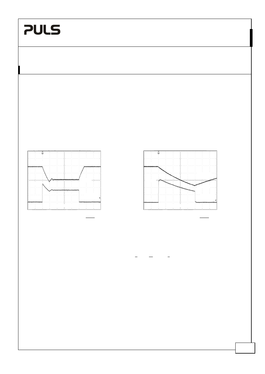
25.1. P
EAK
C
URRENT
C
APABILITY
Solenoids, contactors and pneumatic modules often have a steady state (sealed) coil and a pick-up coil. The inrush
current demand of the pick-up coil is several times higher than the steady state current and usually exceeds the
nominal output current. The same situation applies, when starting a capacitive load.
Branch circuits are often protected with circuit breakers or fuses. In case of a short or an overload in the branch
circuit, the protective device (fuse, circuit breaker) needs a certain amount of over-current to trip or to blow. The
peak current capability ensures the safe operation of subsequent circuit breakers.
Assuming the input voltage is turned on before such an event, the built-in large sized output capacitors inside the
power supply can deliver extra current. Discharging this capacitor causes a voltage dip on the output. The following
two examples show typical voltage dips:
Fig. 25-1 Peak load 1.3A for 50ms, typ.
Fig. 25-2 Peak load 3.15A for 5ms, typ.
10ms/DIV
Output
Voltage
Output
Current
24.5V
0A
1.3A
15.5V
1ms/DIV
Output
Voltage
Output
Current
24.5V
0A
3.15A
11.5V
Peak load 1.3A (resistive) for 50ms
Output voltage dips from 24V to 15.5V.
Peak load 3.15A (resistive) for 5ms
Output voltage dips from 24V to 11.5V.
25.2. B
ACK
-
FEEDING
L
OADS
Loads such as decelerating motors and inductors can feed voltage back to the power supply. This feature is also called
return voltage immunity or resistance against Back- E.M.F. (Electro Magnetic Force).
The maximum allowed feed back voltage is 35Vdc. The absorbing energy can be calculated according to the built-in
large sized output capacitor which is specified in chapter 9.
This power supply is resistant and does not show malfunctioning when a load feeds back voltage to the power
supply. It does not matter, whether the power supply is on or off. However, please note that the output voltage can
dip to zero for approximatelly 200ms if the back-feed voltage is removed.
25.3. I
NDUCTIVE AND
C
APACITIVE
L
OADS
The unit is designed to supply unlimited inductive loads. The max. capacitive load depend on the steady state output
current. At 0.6A output current, the output capacity should not be larger than 660µF at 0.3A output not larger than
2500µF. In case of larger capacitors, the unit can show start-up attempts or start-up problems.
ML15.241
MiniLine
24V, 0.63A, S
INGLE
P
HASE
I
NPUT
Dec. 2007 / Rev. 1.1 DS-ML15.241-EN
All parameters are specified at 24V, 0.63A, 230Vac, 25°C ambient and after a 5 minutes run-in time unless otherwise noted.
www.pulspower.com Phone +49 89 9278 0 Germany
16/20
25.4. S
ERIES
O
PERATION
The power supply can be put in series to increase the output voltage.
Fig. 25-3 Schematic for series operation
Instructions for use in series:
Earth
Unit A
AC
DC
Unit B
AC
DC
-
+
-
+
Load
+
-
a)
It is possible to connect as many units in series as needed,
providing the sum of the output voltage does not exceed
150Vdc.
b)
Voltages with a potential above 60Vdc are not SELV any
more and can be dangerous. Such voltages must be installed
with a protection against touching.
c)
For serial operation use power supplies of the same type.
d)
Earthing of the output is required when the sum of the
output voltage is above 60Vdc.
Note: Avoid return voltage (e.g. from a decelerating motor or
battery) which is applied to the output terminals.
25.5. P
ARALLEL
U
SE TO
I
NCREASE
O
UTPUT
P
OWER
Several power supplies can be paralleled to increase the output power. The ML15.241 has no feature included which
balances the load current between the power supplies. Usually the power supply with the higher adjusted output
voltage draws current until it goes into current limitation. This means no harm to this power supply as long as the
ambient temperature stays below 50°C.
Fig. 25-4 Schematic for parallel operation
Instructions for parallel use:
Unit A
AC
DC
Unit B
AC
DC
-
+
-
+
Load
+
-
a)
Use only power supplies from the same series (ML-Series).
b)
Adjust the output voltages of all power supplies to
approximately the same value (±200mV).
c)
A fuse (or diode) on the output is only required if more than
three units are connected in parallel.
d)
Ensure that the ambient temperature of the power supply
does not exceed 50°C.
ML15.241
MiniLine
24V, 0.63A, S
INGLE
P
HASE
I
NPUT
Dec. 2007 / Rev. 1.1 DS-ML15.241-EN
All parameters are specified at 24V, 0.63A, 230Vac, 25°C ambient and after a 5 minutes run-in time unless otherwise noted.
www.pulspower.com Phone +49 89 9278 0 Germany
17/20
25.6. P
ARALLEL
U
SE FOR
R
EDUNDANCY
Power supplies can be paralleled for redundancy to gain a higher system reliability. Redundant systems require a
certain amount of extra power to support the load in case one power supply unit fails. The simplest way is to put two
MiniLine power supplies in parallel. This is called a 1+1 redundancy. In case one power supply unit fails, the other one
is automatically able to support the load current without any interruption. Redundant systems for a higher power
demand are usually built in a N+1 method. E.g. Five power supplies, each rated for 0.63A are paralleled to build a
2.5A redundant system. If one unit fails, the 2.5A can still be drawn.
Please note: This simple way to build a redundant system has two major disadvantages:
-
The faulty power supply can not be recognized. The green LED will still be on since it is reverse-powered from
the other power supply.
-
It does not cover failures such as an internal short circuit in the secondary side of the power supply. In such a
situation the defective unit becomes a load for the other power supplies and the output voltage can not be
maintained any more.
This above conditions can be avoided by utilizing decoupling diodes which are included in the decoupling module
MLY02.100.
Other recommendations for building redundant power systems:
a)
Use separate input fuses for each power supply.
b)
When possible, connect each power supply to different phases of the mains network.
25.7. C
HARGING OF
B
ATTERIES
The power supply can be used for float-charging of lead-acid or maintenance free 24V VRLA batteries.
Instructions for charging batteries:
a)
Ensure that the ambient temperature of the power supply does not exceed 50°C.
b)
Set the output voltage on a disconnected load, very precisely to the end-of-charge voltage according to the
expected battery temperature.
End-of-charge voltage
27.8V
27.5V
27.15V
26.8V
Battery
temperature
10°C 20°C 30°C 40°C
c)
Use a 1A or 2A circuit breaker (or blocking diode ) between the power supply and the battery.
d)
Ensure that the output current of the power supply is below the allowed charging current of the battery.
e)
Use only matched batteries when putting 12V types in series.
f)
The return current to the power supply is typ. 15mA at 25Vdc
when the power supply is switched off (except in
case a blocking diode is utilized).
25.8. E
XTERNAL
I
NPUT
P
ROTECTION
The unit is tested and approved for branch circuits up to 15A (UL) or 16A (IEC). External protection is only required if
the supplying branch has an ampacity greater than this. In some countries local regulations might apply so check local
codes and requirements.
If an external protective device is utilized, a minimum value is required to avoid undesired tripping of the fuse.
B-Characteristic
C-Characteristic
Ampacity max. 15A (UL), 16A (IEC)
15A (UL), 16A (IEC)
min.
10A 6A
ML15.241
MiniLine
24V, 0.63A, S
INGLE
P
HASE
I
NPUT
Dec. 2007 / Rev. 1.1 DS-ML15.241-EN
All parameters are specified at 24V, 0.63A, 230Vac, 25°C ambient and after a 5 minutes run-in time unless otherwise noted.
www.pulspower.com Phone +49 89 9278 0 Germany
18/20
25.9. F
UNCTIONAL
E
ARTH
T
ERMINAL
From a safety standpoint, the unit is designed according to the requirements for Protection Class 2 which does not
require an earth connection. However, connecting the Functional Earth terminal can be beneficial to gain a high EMI
immunity.
Symmetrical spikes or fast transients on the input side can be conducted directly to earth by the built-in filter
capacitors. The magnitude of such spikes or fast transients on the output side caused by the input are much smaller
compared to not connecting the FE terminal to ground.
Therefore, we recommend to connect the FE terminal too ground.
Fig. 25-5 Functional earth terminal connected to
earth
Fig. 25-6 Functional earth terminal not connected to
earth
Surge
Y
X
L
N
FE
Power Supply
+
-
Surge
X
L
N
Power Supply
+
-
24V
Spike
25.10. O
PERATION ON
T
WO
P
HASES
The power supply can be used on two phases of a three-phase-system
Instructions for two phase operation:
a) A phase to phase connection is allowed as long as the supplying voltage is below 240V
+10%
.
b) Use a fuse or a circuit breaker to protect the N input. The N input is internally not protected and is in this
case connected to a hot wire. Appropriate fuses or circuit breakers are specified in section 25.7 “External
Input Protection”.
Fig. 25-7 Schematic for two phase operation
240V
+
10%
ma
x.
Fuse
L2
L1
L3
L
N
FE
Power Supply
AC
DC
internal
fuse

ML15.241
MiniLine
24V, 0.63A, S
INGLE
P
HASE
I
NPUT
Dec. 2007 / Rev. 1.1 DS-ML15.241-EN
All parameters are specified at 24V, 0.63A, 230Vac, 25°C ambient and after a 5 minutes run-in time unless otherwise noted.
www.pulspower.com Phone +49 89 9278 0 Germany
19/20
25.11. U
SE IN A
T
IGHTLY
S
EALED
E
NCLOSURE
When the power supply is installed in a tightly sealed enclosure, the temperature inside the enclosure will be higher
than the outside. The inside temperature defines the ambient temperature for the power supply.
Results from such an installation:
Power supply is placed in the middle of the box, no other heat producing equipment inside the box
Enclosure:
Rittal Type IP66 Box PK 9510 100, plastic, 130x130x75mm
Input:
230Vac
Load:
24V,
0.63A; load is placed outside the box
Temperature inside the box:
35.9°C (in the middle of the right side of the power supply with a distance of 1cm)
Temperature outside the box:
27.9°C
Temperature rise:
8K
Load:
24V,
0.5A; (=80%) load is placed outside the box
Temperature inside the box:
33.5°C (in the middle of the right side of the power supply with a distance of 1cm)
Temperature outside the box:
27.4°C
Temperature rise:
6.1K
ML15.241
MiniLine
24V, 0.63A, S
INGLE
P
HASE
I
NPUT
Dec. 2007 / Rev. 1.1 DS-ML15.241-EN
All parameters are specified at 24V, 0.63A, 230Vac, 25°C ambient and after a 5 minutes run-in time unless otherwise noted.
www.pulspower.com Phone +49 89 9278 0 Germany
20/20
25.12. M
OUNTING
O
RIENTATIONS
Mounting orientations other than input terminals on the bottom and output on the top requires a reduction in
continuous output power or a limitation in the maximum allowed ambient temperature. The amount of reduction
influences the lifetime expectancy of the power supply. Therefore, two different derating curves for continuous
operation can be found below:
Curve A1
Recommended output power.
Curve A2
Max allowed output power (results approx. in half the lifetime expectancy of A1).
Fig. 25-8
Mounting
Orientation A
Standard
Orientation
Power
Supply
OUTPUT
INPUT
Output Power
0
10
20
30
40
60°C
3
9
12
15W
50
A1
6
Ambient Temperature
Fig. 25-9
Mounting
Orientation B
(Upside down)
Pow
er
Suppl
y
OUTP
UT
INPU
T
Output Power
0
10
20
30
40
60°C
3
9
12
15W
50
6
A1
A2
Ambient Temperature
Fig. 25-10
Mounting
Orientation C
(Table-top
mounting)
Output Power
0
10
20
30
40
60°C
3
9
12
15W
50
6
A1
A2
Ambient Temperature
Fig. 25-11
Mounting
Orientation D
(Horizontal cw)
Po
w
er
S
uppl
y
OUT
P
UT
INP
U
T
Output Power
0
10
20
30
40
60°C
3
9
12
15W
50
6
A1
A2
Ambient Temperature
Fig. 25-12
Mounting
Orientation E
(Horizontal ccw)
Po
w
er
S
uppl
y
OUT
P
UT
INP
U
T
Output Power
0
10
20
30
40
60°C
3
9
12
15W
50
6
A1
A2
Ambient Temperature
Wyszukiwarka
Podobne podstrony:
Datasheet QS10 241 C1
Datasheet ML15 051
Datasheet QT20 241 C1
Datasheet QS20 241
Datasheet ML15 121
Datasheet CD5 241
Datasheet UF20 241
Datasheet QT20 241
Datasheet QS20 241 C1
Datasheet QTD20 241
Datasheet CS10 241
Datasheet UB10 241
Datasheet XT40 241
Datasheet QS5 241
Datasheet QS3 241
Datasheet CS5 241 C1
Datasheet CS3 241
Datasheet UBC10 241
więcej podobnych podstron