
A PRA
CTICAL GUIDE T
O
IEC601
Table of Contents
FOREWORD
5
1. INTRODUCTION TO IEC 601
5
LOCAL ADAPTATION
6
COMMONLY USED DEFINITIONS WITHIN IEC 60601
6
SYMBOLS AND MARKINGS
8
2. VISUAL INSPECTION
9
2. EARTH BOND TESTING
9
4. LEAKAGE MEASUREMENTS
10
IEC 601 BODY MODEL
12
SINGLE FAULT CONDITION
12
EARTH LEAKAGE TEST
13
ENCLOSURE LEAKAGE TEST
14
PATIENT LEAKAGE
15
PATIENT LEAKAGE – F-TYPE
16
PATIENT AUXILIARY CURRENT
17
5. RECORD KEEPING
18
6. CONCLUSION
18
ANNEX A - IEC 60601-1 TEST LIMITS
19
ANNEX B - IEC60601-1 BODY MODEL
19
ANNEX C - PATIENT ENVIRONMENT
20
ANNEX D - IEC 60601 TEST STANDARDS
21

05
Foreword
This booklet is written as a guideline for people involved in testing medical electrical equipment and cannot
be considered to replace the IEC 60601 standard.
All reasonable care has been taken to ensure accuracy of the information. Reference figures and data have
been taken from the latest versions of various standards, guidance notes and recognised ‘best practices’ to
establish the recommended testing requirements,
Rigel Medical, their agents and distributors, accept no responsibility for any error or omissions within this
booklet, or for any misinterpretations by the user. For clarification on any part of this booklet please
contact Rigel Medical before operating any test instrument, under relevant legislation.
No part of this publication shall be deemed to form, or be part of any contract for training or equipment
unless specifically referred to as an inclusion within such contract.
Rigel Medical assumes, that the readers of this booklet are electronic technical competent and therefore
does not accept any liability arising from accidents or fatalities resulting directly or indirectly from the tests
described in this booklet.
1. Introduction to IEC 60601
It can be assumed that not all people will understand the dangers associated with the exposure to electricity.
It is this danger that has triggered several discussions relating to the safety of all members of the public.
Regulatory bodies world-wide have acknowledged the dangers of electricity by producing legislation,
standards and/or guidelines to control the design of electrical appliances in order to prevent any hazard to
the general public.
One environment where electric currents pose an acute threat is in the medical treatment and care of
patients. Often, patients are physically connected to one or more electrical medical devices for a period of
time. In these circumstances it is possible that patients are unaware of being exposed to electrical currents,
especially if patients are treated under full or local anaesthetic. During invasive treatments, the human
body's natural protection organ, the skin, no longer provides the basic insulation against electrical currents.
It is during these treatments that electrical currents as low as 50mA can float through the human body and
cause the heart to fibrillate or paralyse the respiratory system.
To govern the design of medical equipment, the International Electrotechnical Committee, the IEC has
produced a standard to control all aspects of safety directly or indirectly relating to the handling, use or
connection to, of medical equipment. This standard is referenced to as IEC 60601, or by many simply referred
to as IEC 601.
The IEC60601 was first published in 1977 (then referred to as IEC 601) and handles the electrical safety of both
mechanical and electrical issues and is constructed from 2 parts; IEC 60601-1 and IEC 60601-2, each build-up
from a number of basic or collateral standards.
IEC 60601-1-X (X representing a specific standard number between 1-4) is the primary standard and has four
(sub) standards directly relating to the safety of medical equipment.
IEC 60601-2-X (X representing a specific standard number between 1-50). This part of the standard is specific
to various types of medical equipment and provides additional information to the four basic standards.
Annex D provides an overview of the IEC 60101-1-X and IEC 60601-2-X standards.
This booklet describes the electrical safety requirements for compliances with IEC 60601-1. Although a type
test standard, most of these tests are used for regular testing or after service or repair of medical devices.

A PRA
CTICAL GUIDE T
O
IEC601
Local Adaptation
In many cases the IEC 60601 standard has been adapted into local standards for use in
countries around the world. Some examples are EN 60601 (EC), UL2601-1 (USA), CSA C22.2
(Canada) and AS/NZ 3200-1 (Australia / New Zealand).
Clearly, safety testing at the design stage and at the end of the production line are vitally
important, but what about when the equipment enters service? Pending a recognised
international standard for in-service testing, a number of countries have introduced their
own national test recommendations.
Some countries have gone one step further and produced standards or guidelines for
safety testing of newly delivered medical devices (also referred to as acceptance test),
testing during regular intervals, (also referred to as preventive maintenance), or directly
following service or repair. Some examples are MDA DB9801 (UK), VDE 750/751 (Germany),
AS/NZ 3551 (Australia / New Zealand), NFPA / AAMI (USA)
Countries without a national guidance or code of practice mainly follow the
manufacturers instructions or guideline, which most likely refer to the IEC 60601-1 test
requirements and limits to be repeated. In essence all standards have one thing in common
and that is to control the safety of medical devices for use in the treatment, care and
diagnosis of patients and/or individuals.
Commonly used definitions
within IEC 60601
Equipment Under Test
The equipment (EUT) which is the subject of testing.
Device Under Test
The device (DUT) which is the subject of testing.
Applied Part
Part of the medical equipment, which is designed to
come into physical contact with the patient, or parts
that are likely to be brought into contact with the patient.
Patient Connection
Individual physical connections and / or metal parts
intended for connection with the patient, which
form (part of) an Applied Part.

07
Patient Environment
Volumetric area in which a patient can come into contact with
medical equipment or contact can occur between other persons
touching medical equipment and the patient, both intentional
and unintentional. (
see Annex C)
F-Type Applied Part
Applied Part which is electrically isolated from Earth and other parts
of the medical equipment. i.e. floating. F-type applied parts are either
type BF or type CF applied parts.
Type B Applied Part
Applied Part complying with specified requirements for protection against
electric shock. Type B Applied Parts are those parts, which are usually
Earth referenced. Type B are those parts not suitable for direct
cardiac application.
Type BF Applied Part
F-Type Applied Part complying with a higher degree of protection against
electric shock than Type B Applied Parts. Type BF Applied Parts are those
parts not suitable for direct cardiac application.
Type CF Applied Part
F-Type Applied Part complying with the highest degree of protection
against electric shock. Type CF Applied Parts are those parts suitable
for direct cardiac application.
Medical Electrical
Electrical equipment, designed for treatment, monitoring or
Equipment
diagnoses of patients, powered from not more than one connection to
mains supply and which are necessarily in physical or electrical contact
with the patient or transfers energy to or from the patient or detects such
energy transfer to or from the patient.
Medical Electrical
Combination of equipment of which at least one is classed as medical
System
electrical equipment and as such specified by the manufacturer
to be connected by functional connection or use of a multiple portable
socket-outlet.
Class I (Earthed)
Equipment protection against electric shock by additional
protection to basic insulation through means of connecting
exposed conductive parts to the protective earth in the fixed
wiring of the installation.
Class II
Also referred to as Double Insulated. Equipment protection against
electric shock by additional protection to basic insulation through
means of supplementary insulation are provided, there being no
provision for the connection of exposed metalwork of the equipment
to a protective conductor and no reliance upon precautions to be taken
in the fixed wiring of the installation.
NOTE
CLASS II EQUIPMENT may be provided with a FUNCTIONAL
EARTH TERMINAL or a FUNCTIONAL EARTH CONDUCTOR.
A PRA
CTICAL GUIDE T
O
IEC601
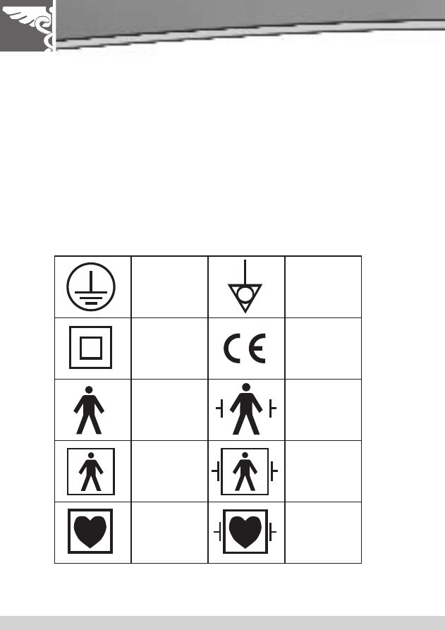
Symbols and Markings
The IEC 60601 has defined the requirements for information / data to be present
on the medical equipment's nameplate, in order to form an unambiguous
identification of the equipment.
Information must include: manufacturers name, model number, serial number,
electrical requirements etc.
The IEC 60601 standard refers to a large variety of symbols for use on medical
equipment, medical systems, accessories and other related parts. A full overview
of the symbols used in IEC 60601 is provided in the standard.
For the purpose of this booklet, a selection of the most commonly used symbols
are displayed below:
Class I
Earth
Reference
point
Class II
i.e.
“Conformité
Européenne”
Type B
Applied Part
Defibrillation
proof type B
Applied Part
Type BF
Applied Part
Defibrillation
proof type BF
Applied Part
Type CF
Applied Part
Defibrillation
proof type CF
Applied Part

09
2. Visual Inspection
The process of visual inspection is not clearly defined by IEC 60601, however visual
inspections form a critical part of the general safety inspections during the functional life
of medical equipment. Upto, 70% of all faults are detected during visual inspection.
Visual inspection is a relatively easy procedure to make sure that the medical equipment in
use is still conform the specifications as released by the manufacturer and has not suffered
from any external damage and or contamination.
These can include the following inspections:
•
Housing / Enclosure;
Look for damage, cracks etc
•
Cabling (supply, applied parts etc);
Look for cuts, wrong connections etc
•
Fuse Rating;
Check correct values after replacement
•
Markings and Labelling;
Check the integrity
•
Integrity of Mechanical Parts;
Check for any obstructions
3. Earthbond Testing
Earthbond Testing, also referred to as Groundbond Testing, tests the integrity of the
low resistance connection between the earth conductor and any metal conductive
parts, which may become live in case of a fault on Class I medical devices. Although
many Class I medical devices are supplied with an earth reference point, most if not
all medical devices require multiple earthbond tests to validate the connections of
additional metal accessible parts on the enclosure.
The test current is applied between the earth pin of the mains supply plug and any
accessible metal part (including earth reference point) via a dedicated earth bond test
lead (clip/probe).
The IEC 60601-1 (clause 8.6.4) requires a minimum test current of 25 Ampere AC or 1.5
times the highest rated current of the relevant circuit(s) which ever is greater. The
open circuit voltage of the current source should not exceed 6V.
A test current of 25 Ampere AC is most commonly used. Due to the exposure of high
current, some (parts of the) equipment could be damaged and thus requiring a lower
test current. However, the earthbond test is designed to stress the connection under
fault conditions.
Faults in the detachable power cord account for 80-90% of all earthbond failures, as
most moulded power cables are prone to stress when the cables are dropped.

A PRA
CTICAL GUIDE T
O
IEC601
For fixed installations (ie MRI or X-RAY equipment) a Point-to-Point continuity
measurement can be made. The resistance is then measured between two probes,
where one would be connected to the incoming earth reference point and one probe
is placed on metal accessible parts of the medical installation.
Test limits are set at 0.1 Ohm for fixed power cords and 0.2 Ohm for equipment with a
detachable power cord. See
Annex A for a full overview of the IEC 60601-1 test limits.
Prolonged use of testing at high currents can lead to a high probe temperature. Care
should be taken to avoid touching the probe tip under these conditions.
4. Leakage Measurements
Research has shown that current not voltage is often the source of injury or death. It
takes only a small amount of current to cause major consequences.
When an electrical current flows through the human body the effect is influenced by
two main factors, firstly the amount of current and secondly the length of time the
current flows.
For example; the heart stops if the current persists for:
a) 250mS at 40mA
b) 100mS at 100mA
c) 50mS
at 200mA
Consider the following examples of the effect of current on the human body when
applied to the skin (non invasive);
0.9
-----1.2mA
Current just perceptible
15.0 -----20.0mA
Release impossible: cannot be tolerated over 15 minutes
50.0 -----100.0mA Ventricular fibrillation, respiratory arrest,
leading directly to death
100.0 -----200.0mA Serious burns and muscular contraction of such a degree
that the thoracic muscles constrict the heart
Compare these values to the fact that 250mA of current is required to power a 25
watt lamp
For this reason, the IEC 60601 committee has set stringent rules on the design of
medical equipment as to prevent any patient or operator being exposed to currents
not part of the functional operation of the device. These currents are referred to as
leakage currents.

11
IEC 60601-1 requires that leakage current measurements of medical devices are performed when
the equipment is powered from an earth referenced supply (through isolation transformer), with
an output voltage of 110% of the rated supply voltage. The medical device must be in full
operational mode and at operational temperature if applicable. In many cases, isolation of
medical devices is only provided by active circuitry; hence true leakage values can ONLY be
measured ones the equipment is in full operation. Equipment that is not in full operation might
result in FALSE low leakage values.
IEC 60601 defines leakage current of three different sources.
•
Earth Leakage; current flowing down the protective earth
conductor of the mains inlet lead.
•
Enclosure Leakage; current flowing to earth through a person
by touching the medical equipment / system or part of.
•
Applied Part or Patient Leakage; current flowing through a person
to earth from the applied part or current flowing from a person
to earth via the applied part by applying unintended voltage
from an external source.
Applied Part / Patient Leakage can be classed into number of measurements such as:
•
Patient Leakage
(please refer to the corresponding paragraph)
•
Patient Auxiliary Leakage
(please refer to the corresponding paragraph)
•
Patient F-type Leakage
(please refer to the corresponding paragraph)
Applied Part or Patient Leakage is the most important part of the leakage measurement on any
medical device. Applied Parts are directly in contact with the patient and are in case of invasive
devices placed under the patient's skin, which forms our natural protection against electrical
currents. Currents applied under the skin can result in far greater consequences. Currents as low
as 15
µA can result in fatality.
The limits for leakage currents within the IEC 60601-1 requirements are set to minimizing the
probability of ventricular fibrillation to a factor as low as 0.002 (Limit of 10
µA for CF Applied
Part under normal condition). See
Annex A for a full overview of the IEC 60601-1 test limits.
The following tests find their origin from the IEC 60601-1 but are specific the AAMI and NFPA 99
standards (USA)
•
Patient Leakage - Applied Part to Ground.
Similar to Patient Leakage described above.
•
Patient Leakage - Applied Part to Case.
Similar to Patient Leakage except that the leakage current path is from
the applied parts, through the patient, to the case of the EUT/DUT.
•
Patient Auxiliary (Applied Part to Applied Part);
Similar to Patient Auxiliary current.
•
Patient Auxiliary (Applied Part to All);
Similar to Patient Auxiliary current.
For the purpose of this booklet, the focus will be on the directly related leakage measurements
as per IEC 60601-1.

A PRA
CTICAL GUIDE T
O
IEC601
WARNING - Mains voltage applied to appliance
It is important to verify that a medical device with moving parts (e.g. motor or pump) is safely
mounted to allow movement without causing damage to equipment or personnel.
Secondary earth paths will effect the leakage measurements and might give false PASS readings.
Always make sure that the device under test is positioned safely and isolated from earth
when measuring leakage.
IEC 601 Body Model
To ensure a traceable simulation of current as if passing through a human body, measurement circuits
have been designed to simulate the average typical electrical characteristics of the human body.
These measurement circuits are referred to as Body Models or Measuring Device (MD in IEC 60601-1)
Some standards such as the AAMI / NFPA 99 and the IEC 61010 (electrical equipment for measurement,
control and Laboratory use) specify different electrical characteristics to that of the IEC 60601-1.
The IEC 60601-1 body model or measuring device is shown in
Annex B.
Single Fault Condition
To maintain a medical device’s high level of protection during it’s operational life, a number of design
features are taken into account to maintain the integrity of the device's electrical safety.
This is done by introducing conditions that could occur under normal use (ie reversed mains supply or
voltage on signal input/output terminals - SIP/SOP) and conditions that can occur under
a single fault condition (SFC).
IEC 60601-1 specifies a number of single fault conditions (SFC) under its clause 8.1. For the purpose of
this booklet, the only highlighted SFC are the interrupted earth connection (Open Earth) and
interruption of any of the supply conductors (Open Neutral).
IEC 60601-1 specifies that all leakage measurements should be carried out using normal and single fault
conditions. A typical part of the electrical safety testing procedures is to perform the test as follows:
1. Normal Supply Voltage
No (SFC)
2. Normal Supply Voltage
Open Neutral
3. Normal Supply Voltage
Open Earth
4. Reversed Supply Voltage
No (SFC)
5. Reversed Supply Voltage
Open Neutral
6. Reversed Supply Voltage
Open Earth
In addition to these test, some manufacturers might choose to include voltage on the signal input /
output terminals (ie communication ports such as USB or RS 232). As this test can be destructive,
it is not commonly used other than during type testing of the medical electrical equipment.
13
Earth Leakage Test
The Earth Leakage Test shows the current flowing through or via the insulation of the medical
device into the protective earth conductor. The earth leakage test is important as it
demonstrates the total leakage from the EUT / DUT.
IEC 60601-1 specifies that the measurements are done under normal and reverse operation and
single fault condition (neutral open circuit). The earth leakage test is valid for Class I
equipment with Types B, BF and CF applied parts.
Annex A shows the pass/fail limits as per IEC
60601-1 requirements.
Note - SFC 'Open Earth’ cannot be performed as this would result in zero leakage
measurements under all circumstances.
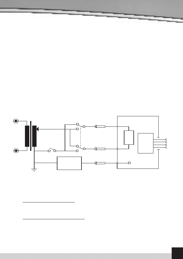
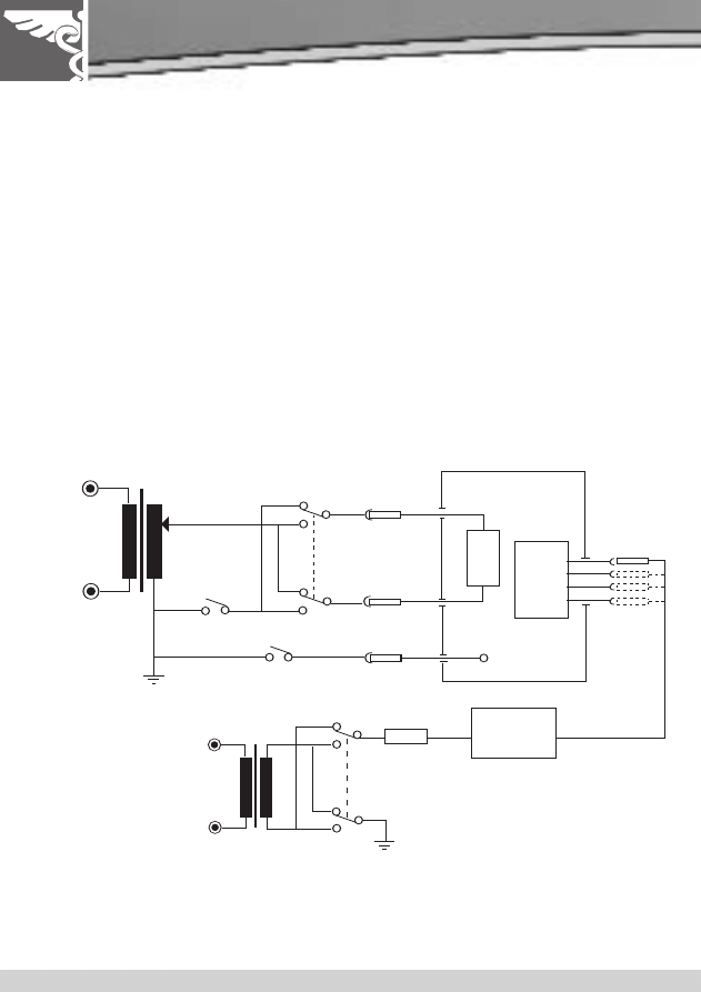
Diagram A shows a schematic interpretation of the earth leakage measurement including the
relays operating the single fault conditions.
Earth Leakage, normal conditions - This test measures the earth leakage current under normal
conditions. The current is measured through the Measuring Device with S1 closed and S5
normal and then S5 reversed.
Earth Leakage, single fault, supply open - This test measures the earth leakage current with a
single fault condition (supply open). The current is measured through the Measuring Device
with S1 open and S5 normal and then S5 reversed.
S5
S1
Equipment
UnderTest
Protective
Earth
Applied
Part
Mains
Part
Measuring
Device
Diagram A - Test Circuit For Earth Leakage
Mains
A PRA
CTICAL GUIDE T
O
IEC601
Enclosure Leakage Test
In general, Enclosure Leakage displays the current that would flow if a person would come in
contact with the housing (or any accessible part not intended for treatment or care) of the
medical device.
IEC 60601-1 specifies that the measurements are done under normal and reverse operation of
the mains supply and single fault conditions Open Neutral circuit and Open Earth. The
Enclosure Leakage Test is valid for both Class 1 and II equipment with Types B, BF and CF
Applied Parts.
Annex A shows the pass/fail limits as per IEC 60601-1 requirements.
Note - for Class II equipment, the Single Fault Earth Open tests are not required.
In the case of Class II devices, or fully insulated enclosures, this can be encapsulated by using
aluminium foil of approximately 200 cm
2
. The enclosure leakage is measured by connecting the
aluminium foil to the leakage tester.
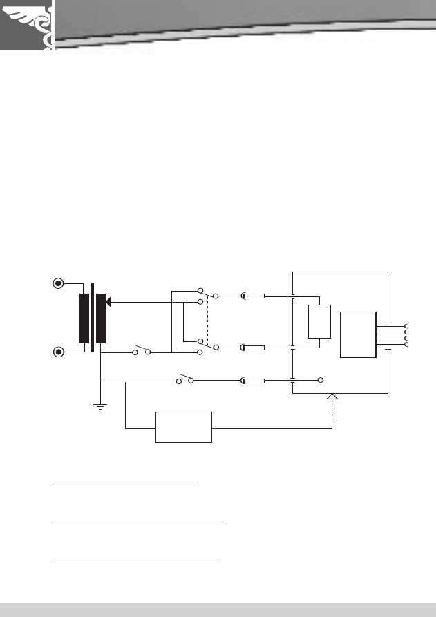
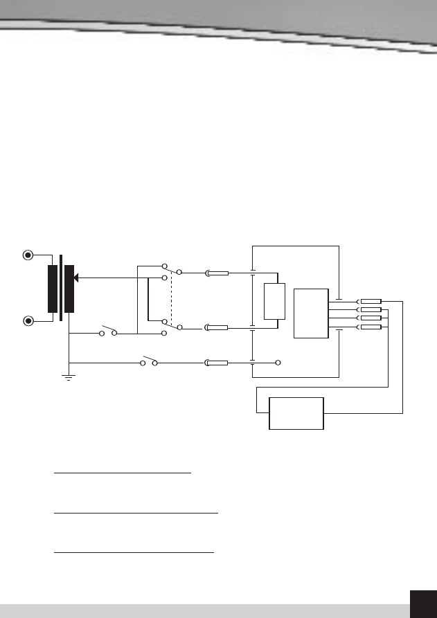
Diagram B shows a schematic interpretation of the earth leakage measurement including the
relays operating the single fault conditions.
Enclosure Leakage, normal condition - This test measures the enclosure leakage current
under normal conditions. The current is measured through the Measuring Device with S1 and
S8 closed and S5 normal and reversed.
Enclosure Leakage, single fault, supply open - This test measures the enclosure leakage
current with a single fault condition (supply open). The current is measured through the
Measuring Device with S1 open, S8 closed and S5 in normal and then S5 reversed.
Enclosure Leakage, single fault, earth open -This test measures the enclosure leakage
current with a single fault condition (earth open). The current is measured through the
Measuring Device with S1 closed, S8 open and S5 in normal and then S5 reversed.
S5
S1
Equipment
UnderTest
Protective
Earth
Applied
Part
Mains
Part
Diagram B - Test Circuit For Enclosure Leakage
Mains
S8
Measuring
Device
S5
S1
Equipment
UnderTest
Protective
Earth
Applied
Part
Mains
Part
Diagram B - Test Circuit For Enclosure Leakage
Mains
S8
Measuring
Device
15
Patient Leakage
The Patient Leakage Current is the current flowing from the Applied Part via the patient to
earth or flowing from the patient via an Applied Part to earth, which originates from an
unintended voltage appearing on an external source.
IEC 60601-1 specifies that the measurements be done under normal and reverse operation of
the mains supply and single fault conditions Open Neutral circuit and Open Earth. The Patient
Leakage Test is valid for both Class 1 and II equipment with Types B, BF and CF applied.
Annex A shows the pass/fail limits as per IEC 60601-1 requirements.
Note For Class II equipment, the Single Fault Earth Open tests are not required.
For type CF equipment the patient leakage current is measured from each applied part
separately however, for type B and BF equipment, the patient leakage current is measured
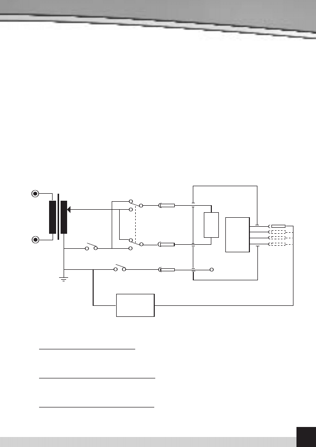
with all applied parts connected together. Diagram C shows a schematic interpretation of the
Patient Leakage measurement including the relays operating the single fault conditions.
Patient Leakage, normal condition - This test measures the patient leakage current under
normal conditions. The current is measured through the Measuring Device with S1 and S8
closed, S5 normal and then S5 reversed.
Patient Leakage, single fault, supply open - This test measures the patient leakage current
with a single fault condition (supply open). The current is measured through the Measuring
Device with S1 open, S8 closed and S5 normal and then S5 reversed.
Patient Leakage, single fault, earth open - This test measures the patient leakage current
with a single fault condition (earth open). The current is measured through the Measuring
Device with S1 closed, S8 open and S5 normal and then S5 reversed.
S5
S1
Equipment
UnderTest
Protective
Earth
Applied
Part
Mains
Part
Measuring
Device
Diagram C - Test Circuit For Patient Leakage Current
Mains
S8
S5
S1
Equipment
UnderTest
Protective
Earth
Applied
Part
Mains
Part
Measuring
Device
Diagram C - Test Circuit For Patient Leakage Current
Mains
S8
A PRA
CTICAL GUIDE T
O
IEC601
Patient Leakage – F-Type
The Patient Leakage F-Type Test (also known as mains on Applied Parts test) displays the current
that would flow if a mains potential was applied to the Applied Part which was attached to a
patient (i.e. a single fault condition). This test is applied only to type BF and CF equipment.
This test involves applying a current limited mains potential (110% of mains input voltage) to the
Applied Parts connections. Due to the requirements for IEC 60601-1 this test current can be in
excess of 5mA under short circuit conditions and as such is hazardous to the user. Caution
should be taken when conducting this test. Current limiting is via a limiting resistor in series
with the measurement circuit.
IEC60601-1 specifies that leakage current for type CF Applied Parts is measured from each of the
patient connection / applied parts separately. For type BF equipment the leakage current is
measured with all parts of the same type applied parts connected together, shown dotted below.
The F-type Leakage test is valid for both Class 1 and II equipment and are measured under mains
normal or reverse and source voltage normal or reverse conditions.
Annex A shows the pass/fail
limits as per IEC 60601-1 requirements.
Diagram D shows a schematic interpretation of the F-Type Leakage measurement including the
relays operating the single fault conditions.
The current is measured through the Measuring Device with S1 and S8 closed. S5 and S9 are
switched between normal and reversed.
S5
S1
Equipment
UnderTest
Protective
Earth
Applied
Part
Mains
Part
Diagram D - Test Circuit For Patient Leakage Current, Mains On Applied Part
Mains
S8
Measuring
Device
Mains
S9
R
S5
S1
Equipment
UnderTest
Protective
Earth
Applied
Part
Mains
Part
Diagram D - Test Circuit For Patient Leakage Current, Mains On Applied Part
Mains
S8
Measuring
Device
Mains
S9
R
17
Patient Auxiliary Current
The Patient Auxiliary Current displays the leakage current that would flow between Applied Parts
under normal and fault conditions. For these tests, current is measured between a single part of the
applied part and all other applied parts connected together. This test should be repeated until all
combinations have been tested. This is also referred to as Applied Part to All.
IEC 60601-1 specifies that the measurements be carried out under normal and reverse operation of
the mains supply and single fault conditions Open Neutral circuit and Open Earth. The Patient
Auxiliary Leakage test is valid for both Class 1 and II equipment with Types B, BF and CF applied.
Note For Class II equipment, the Single Fault Earth Open tests are not required.
Diagram E shows a schematic interpretation of the Patient Auxiliary Leakage measurement
including the relays operating the single fault conditions.
Patient Auxiliary, normal condition - This test measures the patient auxiliary current under
normal conditions. The current is measured through the Measuring Device with S1 and S8 closed, S5
normal and then S5 reversed.
Patient Auxiliary, single fault, supply open - This test measures the patient auxiliary current
under a single fault condition (supply open). The current is measured through the Measuring Device
with S1 open, S8 closed and S5 normal and then S5 reversed.
Patient Auxiliary, single fault, earth open - This test measures the patient auxiliary current under
a single fault condition (earth open). The current is measured through the Measuring Device with S1
closed, S8 open and S5 normal and then S5 reversed.
Equipment
UnderTest
Protective
Earth
Diagram E - Test Circuit For Patient Auxilary Current
S5
S1
Mains
S8
Measuring
Device
Applied
Part
Mains
Part

A PRA
CTICAL GUIDE T
O
IEC601
5. Record Keeping
Currently, manual paper-based systems provide the main method of recording safety testing results
in most hospitals. However, as asset management systems gain more favour as a means of tracking
equipment, PC-based test records are likely to become more popular in the future. Such systems will
enable historical database records to be established to assist in the formulation of preventative
maintenance programmes and also contribute to risk assessment calculations.
Test instrument manufacturers, who have already responded with the introduction of instruments
capable of storing test results for subsequent downloading to printers, are therefore likely to
develop new testers with PC compatible software programmes for records keeping purposes.
Overall, the area of risk assessment and the creation of risk management files has become a growing
feature of routine safety testing decisions, with different organisations and departments drawing-up
individual plans to deal with specific safety hazards.
For the future, therefore, determining the appropriate levels of electrical testing to be taken
without compromising the safety of staff or patients will be central to the introduction of cost
effective yet reliable preventative maintenance campaigns.
6. Conclusion
Electrical safety testing of medical electronic devices remains a crucial part of the overall safety
validation of medical devices and requires specialised test equipment.
When choosing your electrical safety analyser make sure, firstly, that it can be used to test in
accordance with the IEC 60601-1 requirements, and secondly that your analyser will enable you to
accurately and repeatedly produce the results you require.
Essential requirements for electrical safety analysers are:
•
User safety (never compromise)
•
25Ampere AC earth bond (ground bond) testing up to loads exceeding 0.2 Ohm
•
Measuring device meets the frequency response of the IEC 60601-1 body model
•
High accuracy and repeatability of leakage measurement readings (Some
manufacturers might specify accuracy of full scale reading which will effect the
accuracy of low leakage measurements)
•
Traceability of measurement results (Do you require data storage?)
•
Test convenience (test duration, user interface, can you save time?) and reduce
risk of misinterpretation.
Rigel Medical offers a range of test equipment in line with the IEC 60601 requirements.
Please visit our website www.rigelmedical.com for a full overview of our product offering or register
online for our free newsletter on future product releases and product innovations.
For further questions or comments relating to this booklet or on the Rigel Medical product offering,
please contact John Backes via email at johnb@rigelmedical.com
19
Annex A - IEC 60601-1 Test Limits
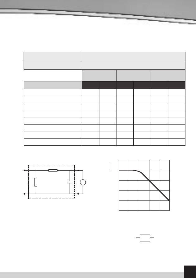
Annex B - IEC 60601 Body Model
Example of a measuring device MD according to IEC 60601-1 and its frequency characteristics
Leakage Current Type
NC
SFC
NC
SFC
NC
SFC
Earth Leakage (General)
0.5mA
1mA
0.5mA
1mA
0.5mA
1mA
Enclosure Leakage
0.1mA
0.5mA
0.1mA
0.5mA
0.1mA
0.5mA
Patient Leakage (dc)
0.01mA
0.05mA
0.01mA
0.05mA
0.01mA
0.05mA
Patient Leakage (ac)
0.1mA
0.5mA
0.1mA
0.5mA
0.01mA
0.05mA
Patient Leakage (F-Type)
NA
NA
NA
5mA
NA
0.05mA
Patient Leakage
(Mains on SIP/SOP)
NA
5mA
NA
NA
NA
NA
Patient Auxiliary Current (dc)
0.01mA
0.05mA
0.01mA
0.05mA
0.01mA
0.05mA
Patient Auxiliary Current (ac)
0.1mA
0.5mA
0.1mA
0.5mA
0.01mA
0.05mA
Type B
Applied Parts
Type BF
Applied Parts
Type CF
Applied Parts
Non Detachable power cord
< 0.1
Ω
Detachable power cord
< 0.2
Ω
Earthbond test limit at 25A, 50Hz
R
1
R
2
C
1
Z
Voltage
measuring
instrument
b)
R
1
R
2
C
1
= 10 k
Ω±5%
a)
= 1 k
Ω±5%
a)
= 0,015
µF±5%
a) Measuring device
b) Frequency characteristics
Frequency(
ƒ) in Hz
R
e
la
t
iv
e
m
a
g
n
it
u
d
e
c
)
(d
b
):
2
0
lo
g
Z
(ƒ
)
Z
(ƒ
=
1
0
)
+20
0
-20
-40
-60
10
10
2
10
3
10
4
10
5
10
6
v
NOTE
The network and voltage measuring instrument above are replaced by the symbol in the following figures
MD
Non inductive components
Impedance >> measuring impedance Z
Z(
ƒ) is the transfer impedance of the network, i.e. V
out/in
, for a current frequency
ƒ.
a)
b)
c)
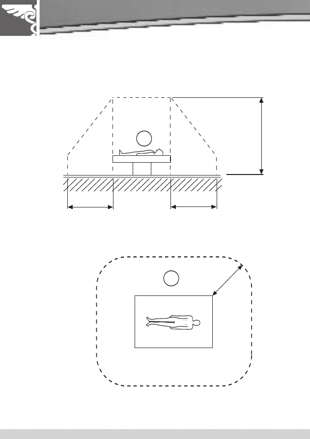
Annex C - Patient Environment
A PRA
CTICAL GUIDE T
O
IEC601
1.5m
1.5m
2.5m
1
1
1.
5m
IEC 60601-1-1
MEDICAL ELECTRICAL EQUIPMENT – PART 1: GENERAL REQUIREMENTS FOR SAFETY 1: COLLATERAL STANDARD:
SAFETY REQUIREMENTS FOR MEDICAL ELECTRICAL SYSTEMS
IEC 60601-1-2
MEDICAL ELECTRICAL EQUIPMENT – PART 1: GENERAL REQUIREMENTS FOR SAFETY 2. COLLATERAL STANDARD:
ELECTROMAGNETIC COMPATIBILITY –REQUIREMENTS AND TESTS
IEC 60601-1-3
MEDICAL ELECTRICAL EQUIPMENT – PART 1: GENERAL REQUIREMENTS FOR SAFETY – COLLATERAL STANDARD:
GENERAL REQUIREMENTS FOR RADIATION PROTECTION IN DIAGNOSTIC X-RAY EQUIPMENT
IEC 60601-1-4
MEDICAL ELECTRICAL EQUIPMENT: PART 1-4: GENERAL REQUIREMENTS FOR COLLATERAL STANDARD:
PROGRAMMABLE ELECTRICAL MEDICAL SYSTEMS
Annex D - IEC 60601 Test Standards
Table 1 – IEC 60601 Collateral Standards
(© IEC Geneva, Switzerland)
IEC 60601-2-1
MEDICAL ELECTRICAL EQUIPMENT - PART 2-1: PARTICULAR REQUIREMENTS FOR THE SAFETY OF ELECTRON
ACCELERATORS IN THE RANGE 1 MeV TO 50 MeV
IEC 60601-2-2
MEDICAL ELECTRICAL EQUIPMENT - PART 2-2: PARTICULAR REQUIREMENTS FOR THE SAFETY OF HIGH
FREQUENCY SURGICAL EQUIPMENT
IEC 60601-2-3
MEDICAL ELECTRICAL EQUIPMENT PART 2: PARTICULAR REQUIREMENTS FOR THE SAFETY OF SHORT-WAVE
THERAPY EQUIPMENT
IEC 60601-2-4
MEDICAL ELECTRICAL EQUIPMENT PART 2: PARTICULAR REQUIREMENTS FOR THE SAFETY OF CARDIAC
DEFIBRILLATORS AND CARDIAC DEFIBRILLATORS MONITORS
IEC 60601-2-5
MEDICAL ELECTRICAL EQUIPMENT - PART 2-5: PARTICULAR REQUIREMENTS FOR THE SAFETY OF ULTRASONIC
PHYSIOTHERAPY EQUIPMENT
IEC 60601-2-6
MEDICAL ELECTRICAL EQUIPMENT - PART 2: PARTICULAR REQUIREMENTS FORTHE SAFETY OF MICROWAVE
THERAPY EQUIPMENT
IEC 60601-2-7
MEDICAL ELECTRICAL EQUIPMENT - PART 2-7: PARTICULAR REQUIREMENTS FOR THE SAFETY OF HIGH-VOLTAGE
GENERATORS OF DIAGNOSTIC X-RAY GENERATORS
IEC 60601-2-8
MEDICAL ELECTRICAL EQUIPMENT - PART 2-8: PARTICULAR REQUIREMENTS FOR THE SAFETY OF THERAPEUTIC
X-RAY EQUIPMENT OPERATING IN THE RANGE 10 kV TO 1 MV
IEC 60601-2-9
MEDICAL ELECTRICAL EQUIPMENT - PART 2: PARTICULAR REQUIREMENTS FORTHE SAFETY OF PATIENT
CONTACT DOSEMETERS USED IN RADIOTHERAPY WITHELECTRICALLY CONNECTED RADIATION DETECTORS
IEC 60601-2-10
MEDICAL ELECTRICAL EQUIPMENT PART 2: PARTICULAR REQUIREMENTS FOR THE SAFETY OF NERVE AND
MUSCLE STIMULATORS
IEC 60601-2-12
MEDICAL ELECTRICAL EQUIPMENT PART 2: PARTICULAR REQUIREMENTS FOR THE SAFETY OF GAMMA BEAM
THERAPHY EQUIPMENT
IEC 60601-2-11
MEDICAL ELECTRICAL EQUIPMENT - PART 2: PARTICULAR REQUIREMENTS FORTHE SAFETY OF LUNG
VENTILATORS FOR MEDICAL USE
IEC 60601-2-13
MEDICAL ELECTRICAL EQUIPMENT - PART 2-13: PARTICULAR REQUIREMENTS FOR THE SAFETY OF ANAESTHETIC
WORKSTATIONS
IEC 60601-2-14
MEDICAL ELECTRICAL EQUIPMENT - PART 2: PARTICULAR REQUIREMENTS FORTHE SAFETY OF
ELECTROCONVULSIVE THERAPY EQUIPMENT
IEC 60601-2-15
MEDICAL ELECTRICAL EQUIPMENT - PART 2: PARTICULAR REQUIREMENTS FORTHE SAFETY OF CAPACITOR
DISCHARGE X-RAY GENERATORS
IEC 60601-2-16
MEDICAL ELECTRICAL EQUIPMENT - PART 2: PARTICULAR REQUIREMENTS FORTHE SAFETY OF HAEMODIALYSIS
EQUIPMENT
IEC 60601-2-17
MEDICAL ELECTRICAL EQUIPMENT - PART 2: PARTICULAR REQUIREMENTS FORTHE SAFETY OF
REMOTE- CONTROLLED AUTOMATICALLY DRIVEN GAMMARAY AFTER-LOADING EQUIPMENT
IEC 60601-2-18
MEDICAL ELECTRICAL EQUIPMENT PART 2: PARTICULAR REQUIREMENTS FOR THE SAFETY OF ENDOSCOPIC
EQUIPMENT
IEC 60601-2-19
MEDICAL ELECTRICAL EQUIPMENT - PART 2: PARTICULAR REQUIREMENTS OF SAFETY OF BABY INCUBATORS
IEC 60601-2-20
MEDICAL ELECTRICAL EQUIPMENT - PART 2: PARTICULAR REQUIREMENTS FOR THE SAFETY OF TRANSPORT
INCUBATORS
IEC 60601-2-21
MEDICAL ELECTRICAL EQUIPMENT PART 2: PARTICULAR REQUIREMENTS FOR THE SAFETY OF INFANT RADIANT
WARMERS
Table 2 – IEC 60601 Specific Standards
(© IEC Geneva, Switzerland)
21

IEC 60601-2-22
MEDICAL ELECTRICAL EQUIPMENT - PART 2: PARTICULAR REQUIREMENTS FOR THE SAFETY OF DIAGNOSTIC AND
THERAPEUTIC LASER EQUIPMENT
IEC 60601-2-23
MEDICAL ELECTRICAL EQUIPMENT - PART 2-23: PARTICULAR REQUIREMENTS FOR THE SAFETY, INCLUDING
ESSENTIAL PERFORMANCE, OF TRANSCUTANEOUSPARTIAL PRESSURE MONITORING EQUIPMENT
IEC 60601-2-24
MEDICAL ELECTRICAL EQUIPMENT - PART 2-24: PARITCULAR REQUIREMENTS FOR THE SAFETY OF INFUSION PUMPS
AND CONTROLLERS
IEC 60601-2-25
MEDICAL ELECTRICAL EQUIPMENT - PART 2-25: PARTICULAR REQUIREMENTS FOR THE SAFETY OF
ELECTROCARDIOGRAPHS
IEC 60601-2-26
MEDICAL ELECTRICAL EQUIPMENT PART 2: PARTICULAR REQUIREMENTS FOR THE SAFETY OF
ELECTROENCEPHALOGRAPHS
IEC 60601-2-27
MEDICAL ELECTRICAL EQUIPMENT - PART 2: PARTICULAR REQUIREMENTS FORTHE SAFETY OF
ELECTROCARDIOGRAPHIC MONITORING EQUIPMENT
IEC 60601-2-28
MEDICAL ELECTRICAL EQUIPMENT - PART 2: PARTICULAR REQUIREMENTS FOR THE SAFETY OF X-RAY SOURCE
ASSEMBLIES AND X-RAY TUBE ASSEMBLIES FOR MEDICAL DIAGNOSIS
IEC 60601-2-29
MEDICAL ELECTRICAL EQUIPMENT - PART 2-29: PARTICULAR REQUIREMENTS FOR THE SAFETY OF RADIOTHERAPHY
SIMULATORS
IEC 60601-2-30
MEDICAL ELECTRICAL EQUIPMENT - PART 2-30: PARTICULAR REQUIREMENTS FOR THE SAFETY, INCLUDING
ESSENTIAL PERFORMANCE, OF AUTOMATIC CYCLING NON-INVASIVE BLOOD PRESSURE MONITORING EQUIPMENT
IEC 60601-2-31
MEDICAL ELECTRICAL EQUIPMENT - PART 2: PARTICULAR REQUIREMENTS FOR THE SAFETY OF EXTERNAL CARDIAC
PACEMAKERS WITH INTERNAL POWER SOURCE
IEC 60601-2-32
MEDICAL ELECTRICAL EQUIPMENT PART 2: PARTICULAR REQUIREMENTS FOR THE SAFETY OF ASSOCIATED
EQUIPMENT OF X-RAY EQUIPMENT
IEC 60601-2-33
MEDICAL ELECTRICAL EQUIPMENT - PART 2: PARTICULAR REQUIREMENTS FORTHE SAFETY OF MAGNETIC
RESONANCE EQUIPMENT FOR MEDICAL DIAGNOSIS
IEC 60601-2-34
MEDICAL ELECTRICAL EQUIPMENT - PART 2: PARTICULAR REQUIREMENTS FOR THE SAFETY, INCLUDING ESSENTIAL
PERFORMANCE, OF INVASIVE BLOOD PRESSURE MONITORING EQUIPMENT
IEC 60601-2-35
MEDICAL ELECTRICAL EQUIPMENT - PART 2: PARTICULAR REQUIREMENTS FORTHE SAFETY OF BLANKETS, PADS AND
MATTRESSES, INTENDED FOR HEATING IN MEDICAL USE
IEC 60601-2-36
MEDICAL ELECTRICAL EQUIPMENT - PART 2: PARTICULAR REQUIREMENTS FORTHE SAFETY OF EQUIPMENT FOR
EXTRACORPOREALLY INDUCED LITHOTRIPSY
IEC 60601-2-38
MEDICAL ELECTRICAL EQUIPMENT - PART 2: PARTICULAR REQUIREMENTS FORTHE SAFETY OF ELECTRICALLY
OPERATED HOSPITAL BEDS
IEC 60601-2-39
MEDICAL ELECTRICAL EQUIPMENT - PART 2-39: PARTICULAR REQUIREMENTS FOR THE SAFETY OF PERITONEAL
DIALYSIS EQUIPMENT
IEC 60601-2-40
MEDICAL ELECTRICAL EQUIPMENT - PART 2-40: PARTICULAR REQUIREMENTS FOR THE SAFETY OF
ELETROMYOGRAPHS AND EVOKED RESPONSE EQUIPMENT
IEC 60601-2-41
MEDICAL ELECTRICAL EQUIPMENT - PART 2-41: PARTICULAR REQUIREMENTS FOR THE SAFETY OF SURGICAL
LUMINAIRES AND LUMINAIRES FOR DIAGNOSIS
IEC 60601-2-43
MEDICAL ELECTRICAL EQUIPMENT - PART 2-43: PARTICULAR REQUIREMENTS FOR THE SAFETY OF X-RAY EQUIPMENT
FOR INTERVENTIONAL PROCEDURES
IEC 60601-2-44
MEDICAL ELECTRICAL EQUIPMENT - PART 2-44: PARTICULAR REQUIREMENTS FOR THE SAFETY OF X-RAY EQUIPMENT
FOR COMPUTED TOMOGRAPHY
IEC 60601-2-45
MEDICAL ELECTRICAL EQUIPMENT - PART 2-45: PARTICULAR REQUIREMENTS FOR THE SAFETY OF MAMMOGRAPHIC
X-RAY EQUIPMENT AND MAMMOGRAPHIC STEREOTACTIC DEVICES
IEC 60601-2-46
MEDICAL ELECTRICAL EQUIPMENT - PART 2-46: PARTICULAR REQUIREMENTS FOR THE SAFETY OF OPERATING
TABLES
IEC 60601-2-50
MEDICAL ELECTRICAL EQUIPMENT - PART 2-5O: PARTICULAR REQUIREMENTS FOR THE SAFETY OF INFANT
PHOTOTHERAPY EQUIPMENT
A PRA
CTICAL GUIDE T
O
IEC601
Wyszukiwarka
Podobne podstrony:
A Practical Guide to Marketing Nieznany
Borderline Personality Disorder A Practical Guide to Treatment
The Four Agreements A Practical Guide to Personal Freedom A Toltec Wisdom Book by Don Miguel Ruiz T
A Practical Guide to Quantitation with Solid Phase Microextr
A Practical Guide to High Speed Printed Circuit Board Layout
(philosophy) a practical guide to critical thinking
a grimoire for modern cunningfolk a practical guide to witch
Terry Anderson, Laura E Huggins Property Rights, A Practical Guide to Freedom and Prosperity (2003)
Santeria A Practical Guide to Afro Caribbean Magic by Luis M Nuñez
Alan Belkin A Practical Guide to Musical Composition
Practical Guide To Critical Thinking
A Practical Guide to Teaching Science in the Secondary School (Routledge Teaching Guides)
Eason, Cassandra A Practival Guide to Witchcraft and Magic
The Lecturer s Toolkit A Practical Guide to Assessment, Learning and Teaching
Antisocial Personality Disorder A Practitioner s Guide to Comparative Treatments (Comparative Treatm
Quick Guide to Practical Magick
więcej podobnych podstron