PROPERTIES OF MAGNETIC MATERIALS
H. P. R. Frederikse
Glossary of Symbols
Units
Quantity
Symbol
SI
emu
Magnetic field
H
A m
-1
Oe (oersted)
Magnetic induction
B
T (tesla)
G (gauss)
Magnetization
M
A m
-1
emu cm
-3
Spontaneous magnetization
M
s
A m
-1
emu cm
-3
Saturation magnetization
M
0
A m
-1
emu cm
-3
Magnetic flux
Φ
Wb (weber)
maxwell
Magnetic moment
m, µ
A m
2
erg/G
Coercive field
H
c
A m
-1
Oe
Remanence
B
r
T
G
Saturation magnetic polarization
J
s
T
G
Magnetic susceptibility
χ
Magnetic permeability
µ
H m
–1
(henry/meter)
Magnetic permeability of free space
µ
0
H m
–1
Saturation magnetostriction
λ (∆l/l)
Curie temperature
T
C
K
K
Néel temperature
T
N
K
K
Magnetic moment µ = γħJ = g µ
B
J
where
γ = gyromagnetic ratio; J = angular momentum; g = spectroscopic splitting factor (~2)
µ
Β
= bohr magneton = 9.2741⋅10
–24
J/T = 9.2741⋅10
–21
erg/G
Earth’s magnetic field H = 56 A m
–1
= 0.7 Oe
For iron: M
0
= 1.7⋅10
6
A m
–1
; B
r
= 0.8⋅10
6
A m
–1
1 Oe = (1000/4π) A m
–1
; 1 G = 10
–4
T; 1 emu cm
–3
= 10
3
A m
–1
1 maxwell = 10
–8
Wb
µ
0
= 4π 10
–7
H m
–1
Relation Between Magnetic Induction and Magnetic Field
(a)
(b)
(c)
(c)
+H
c
-H
c
-B
r
+B
r
(a)
(b)
(c)
=
=
=
Domain growth
Field removal
Hysteric curve on field
H
B
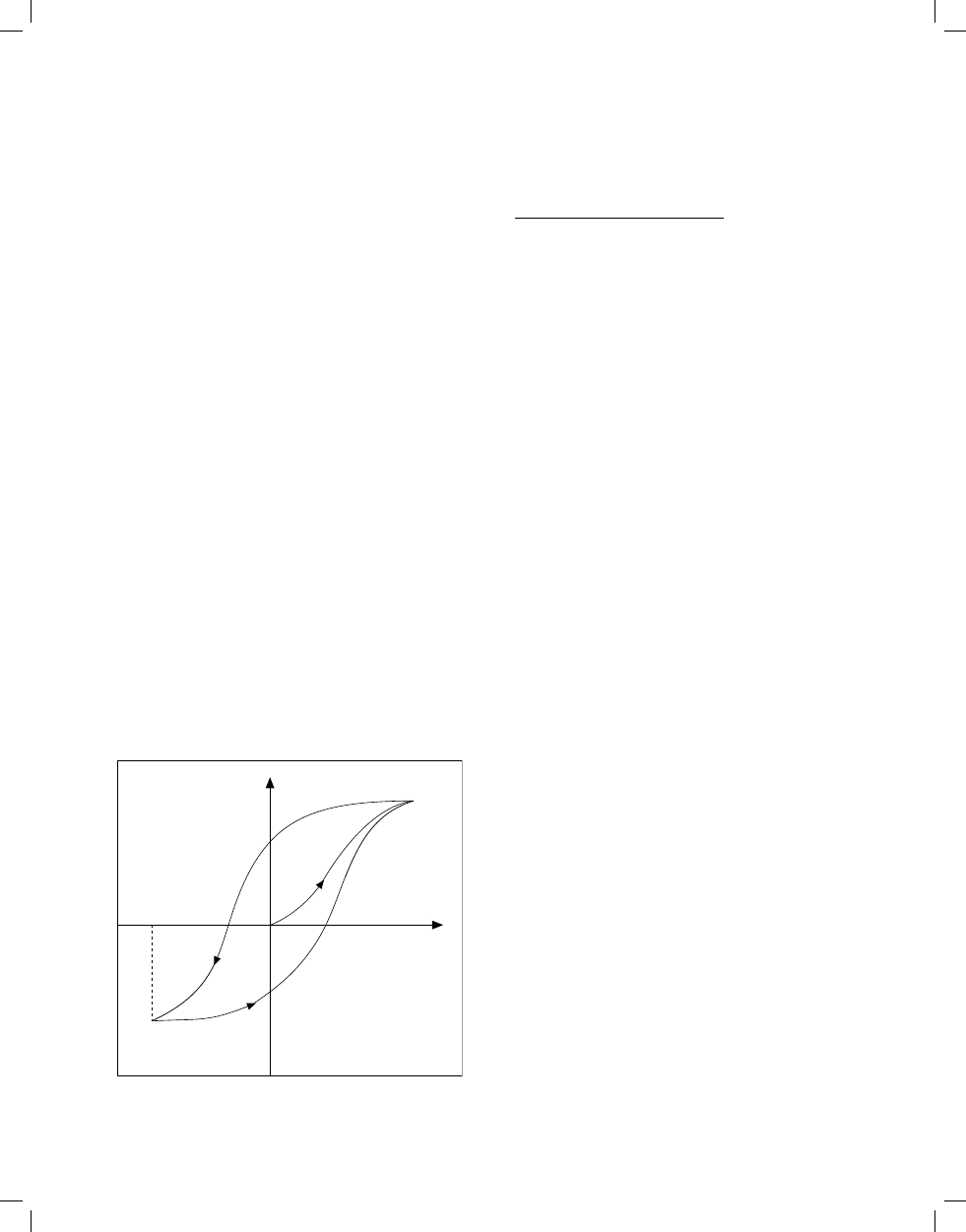
FIGURE 1. Typical curve representing the dependence of magnetic in-
duction B on magnetic field H for a ferromagnetic material. When H is
first applied, B follows curve a as the favorably oriented magnetic domains
grow. This curve flattens as saturation is approached. When H is then re-
duced, B follows curve b, but retains a finite value (the remanence B
r)
at
H = 0. In order to demagnetize the material, a negative field –H
c
(where H
c
is called the coercive field or coercivity) must be applied. As H is further
decreased and then increased to complete the cycle (curve
c), a hysteresis
loop is obtained. The area within this loop is a measure of the energy loss
per cycle for a unit volume of the material.
12-100
Section 12.indb 100
4/28/05 1:57:29 PM
Hard
H
B
Soft
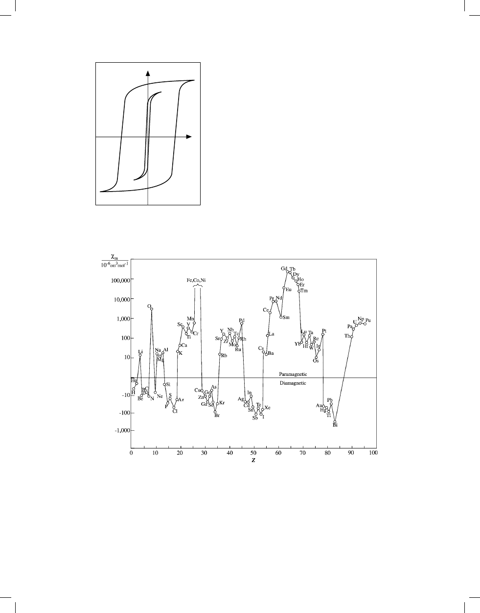
FIGURE 2. Schematic curve illustrating the B vs. H dependence for hard
and soft magnetic materials. Hard materials have a larger remanence and
coercive field, and a correspondingly large hysteresis loss.
Reference
Ralls, K. M., Courtney, T. H., and Wulff, J., Introduction to Materials
Science and Engineering, J. Wiley & Sons, New York, 1976, p. 577, 582.
With permission.
Magnetic Susceptibility of the Elements
FIGURE 3. Molar susceptibility of the elements at room temperature (cgs units of 10
–6
cm
3
/mol). Values are not available for Z = 9, 61, and 84–89; Fe,
Co, and Ni (Z = 26–28) are ferromagnetic. Data taken from the table “Magnetic Susceptibility of the Elements and Inorganic Compounds” in Section 4.
Reference
Gray, D. E., Ed., American Institute of Physics Handbook, Third Edition, McGraw Hill, New York, 1972, p. 5–224. With permission.
Properties of Magnetic Materials
12-101
Section 12.indb 101
4/28/05 1:57:31 PM

Ground State of Ions with Partly Filled d or f Shells
Z
Element
n
S
L
J
Gr. state
p
calc
a
p
calc
b
p
meas
22
Ti
3+
1
1/2
2
3/2
2
D
3/2
1.73
1.55
1.8
23
V
4+
1
1/2
2
3/2
2
D
3/2
1.73
1.55
1.8
23
V
3+
2
1
3
2
3
F
2
2.83
1.63
2.8
23
V
2+
3
3/2
3
3/2
4
F
3/2
3.87
0.77
3.8
24
Cr
3+
3
3/2
3
3/2
4
F
3/2
3.87
0.77
3.7
25
Mn
4+
3
3/2
3
3/2
4
F
3/2
3.87
0.77
4.0
24
Cr
2+
4
2
2
0
5
D
0
4.90
0
4.9
25
Mn
3+
4
2
2
0
5
D
0
4.90
0
5.0
25
Mn
2+
5
5/2
0
5/2
6
S
5/2
5.92
5.92
5.9
26
Fe
3+
5
5/2
0
5/2
6
S
5/2
5.92
5.92
5.9
26
Fe
2+
6
2
2
4
5
D
4
4.90
6.70
5.4
27
Co
2+
7
3/2
3
9/2
4
F
9/2
3.87
6.54
4.8
28
Ni
2+
8
1
3
4
3
F
4
2.83
5.59
3.2
29
Cu
2+
9
1/2
2
5/2
2
D
5/2
1.73
3.55
1.9
p
calc
c
58
Ce
3+
1
1/2
3
5/2
2
F
5/2
2.54
2.4
59
Pr
3+
2
1
5
4
3
H
4
3.58
3.5
60
Nd
3+
3
3/2
6
9/2
4
I
9/2
3.62
3.5
61
Pm
3+
4
2
6
4
5
I
4
2.68
62
Sm
3+
5
5/2
5
5/2
6
H
5/2
0.84
1.5
63
Eu
3+
6
3
3
0
7
F
0
0.0
3.4
64
Gd
3+
7
7/2
0
7/2
8
S
7/2
7.94
8.0
65
Tb
3+
8
3
3
6
7
F
6
9.72
9.5
66
Dy
3+
9
5/2
5
15/2
6
H
15/2
10.63
10.6
67
Ho
3+
10
2
6
8
5
I
8
10.60
10.4
68
Er
3+
11
3/2
6
15/2
4
I
15/2
9.59
9.5
69
Tm
3+
12
1
5
6
3
H
6
7.57
7.3
70
Yb
3+
13
1/2
3
7/2
2
F
7/2
4.54
4.5
a
p
calc
= 2[S(S + 1)]
1/2
b
p
calc
= 2[J(J + 1)]
1/2
c
p
calc
= g[J(J + 1)]
1/2
References
1. Jiles, D., Magnetism and Magnetic Materials, Chapman & Hall,
London, 1991, p. 243.
2. Kittel, C., Introduction to Solid State Physics, 6th Edition, J. Wiley &
Sons, New York, 1986, pp. 405–406.
3. Ashcroft, N. W. and Mermin, N. D., Solid State Physics, Holt, Rinehart,
and Winston, New York, 1976, p. 652.
12-102
Properties of Magnetic Materials
Section 12.indb 102
4/28/05 1:57:33 PM

Ferro- and Antiferromagnetic Elements
M
0
is the saturation magnetization at T = 0 K
n
B
is the number of Bohr magnetons per atom
T
C
is the Curie temperature
T
N
is the Néel temperature
M
0
/gauss
n
B
T
C
/K
T
N
/K
Comments
Fe
22020
2.22
1043
Co
18170
1.72
1388
Ni
6410
0.62
627
Cr
311
Mn
100
Ce
12.5
c-Axis antiferromagnetic
Nd
19.2
Basal plane modulation on hexagonal sites
7.8
Cubic sites order (periodicity different from high-T phase)
Sm
106
Ordering on hexagonal sites
13.8
Cubic site order
Eu
90.5
Spiral along cube axis
Gd
24880
7
293
Tb
9
220
Basal plane ferromagnet
230.2
Basal plane spiral
Dy
10
87
Basal plane ferromagnet
176
Basal plane spiral
Ho
10
20
Bunched cone structure
133
Basal plane spiral
Er
9
32
c-Axis ferrimagnetic cone structure
80
c-Axis modulated structure
Tm
7
32
c-Axis ferrimagnetic cone structure
56
c-Axis modulated structure
References
1. Ashcroft, N. W., and Mermin, N. D., Solid State Physics, Holt, Rinehart,
and Winston, New York, 1976, p.652.
2. Gschneidner, K. A., and Eyring, L., Handbook on the Physics and
Chemistry of Rare Earths, North Holland Publishing Co., Amsterdam,
1978.
Selected Ferromagnetic Compounds
M
0
is the saturation magnetization at T = 293 K
T
C
is the Curie temperature
Compound
M
0
/gauss
T
C
/K
Crystal system
MnB
152
578
orthorh(FeB)
MnAs
670
318
hex(FeB)
MnBi
620
630
hex(FeB)
MnSb
710
587
hex(FeB)
Mn
4
N
183
743
MnSi
34
cub(FeSi)
CrTe
247
339
hex(NiAs)
CrBr
3
270
37
hex(BiI
3
)
CrI
3
68
hex(BiI
3
)
CrO
2
515
386
tetr(TiO
2
)
EuO
1910*
77
cub
EuS
1184*
16.5
cub
GdCl
3
550*
2.2
orthorh
FeB
598
orthorh
Fe
2
B
1043
tetr (CuAl
2
)
FeBe
5
75
cub(MgCu
2
)
Fe
3
C
483
orthorh
FeP
215
orthorh (MnP)
*
At T = 0 K
References
1. Kittel, C., Introduction to Solid State Physics, 6th Edition, J. Wiley &
Sons, New York, 1986.
2. Ashcroft, N. W., and Mermin, N. D., Solid State Physics, Holt, Rinehart,
and Winston, New York, 1976.
Properties of Magnetic Materials
12-103
Section 12.indb 103
4/28/05 1:57:34 PM

Magnetic Properties of High-Permeability Metals and Alloys (Soft)
µ
i
is the initial permeability
µ
m
is the maximum permeability
H
c
is the coercive force
J
s
is the saturation polarization
W
H
is the hysteresis loss per cycle
T
C
is the Curie temperature
Material
Composition (mass %)
µ
i
/µ
0
µ
m
/µ
0
H
c
/A m
–1
J
s
/T
W
H
/J m
–3
T
C
/K
Iron
Commercial 99Fe
200
6000
70
2.16
500
1043
Iron
Pure 99.9Fe
25000
350000
0.8
2.16
60
1043
Silicon-iron
96Fe-4Si
500
7000
40
1.95
50–150
1008
Silicon-iron (110) [001]
97Fe-3Si
9000
40000
12
2.01
35–140
1015
Silicon-iron {100} <100>
97Fe-3Si
100000
6
2.01
1015
Mild steel
Fe-0.1C-0.1Si-0.4Mn
800
1100
200
Hypernik
50Fe-50Ni
4000
70000
4
1.60
22
753
Deltamax {100} <100>
50Fe-50Ni
500
200000
16
1.55
773
Isoperm {100} <100>
50Fe-50Ni
90
100
480
1.60
78 Permalloy
78Ni-22Fe
4000
100000
4
1.05
50
651
Supermalloy
79Ni-16Fe-5Mo
100000
1000000
0.15
0.79
2
673
Mumetal
77Ni-16Fe-5Cu-2Cr
20000
100000
4
0.75
20
673
Hyperco
64Fe-35Co-0.5Cr
650
10000
80
2.42
300
1243
Permendur
50Fe-50Co
500
6000
160
2.46
1200
1253
2V-Permendur
49Fe-49Co-2V
800
4000
160
2.45
600
1253
Supermendur
49Fe-49Co-2V
60000
16
2.40
1150
1253
25Perminvar
45Ni-30Fe-25Co
400
2000
100
1.55
7Perminvar
70Ni-23Fe-7Co
850
4000
50
1.25
Perminvar (magnet. annealed)
43Ni-34Fe-23Co
400000
2.4
1.50
Alfenol (or Alperm)
84Fe-16Al
3000
55000
3.2
0.8
723
Alfer
87Fe-13Al
700
3700
53
1.20
673
Aluminum-Iron
96.5Fe-3.5Al
500
19000
24
1.90
Sendust
85Fe-10Si-5Al
36000
120000
1.6
0.89
753
References
1. McCurrie, R. A., Structure and Properties of Ferromagnetic Materials,
Academic Press, London, 1994, p. 42.
2. Gray, D. E., Ed., American Institute of Physics Handbook, Third
Edition, McGraw Hill, New York, 1972, p. 5–224.
Applications of High-Permeability Materials
Applications
Requirements
Power applications
Distribution and power transformers
Low core losses, high permeability, high saturation magnetic polarization
High-quality motors and generators, stators and armatures, switched-
mode power supplies
Instrument transformers
Audiofrequency transformers
Low core losses, high permeability, high magnetic polarization
Pulse transformers
High permeability
Cores for inductor coils
Audiofrequency
Low hysteresis, high permeability
Carrier frequency
Very low hysteresis and eddy current loss
Radiofrequency
High permeability at low fields
Miscellaneous
Relays, switches
Earth leakage circuit
}
High permeability, low remanence, low coercivity
Magnetic shielding
Low core loss for AC applications
12-104
Properties of Magnetic Materials
Section 12.indb 104
4/28/05 1:57:35 PM

Applications of High-Permeability Materials
Applications
Requirements
Magnetic recording heads
High initial permeability, low or zero remanence
Magnetic amplifiers
Saturable reactors
Saturable transformers
}
Transformer cores
Rectangular hysteresis loops, low hysteresis loss
Magnetic shunts for temperature compensation in magnetic circuits
Low Curie temperature, appropriate decrease in permeability with
increase in temperature
Electromagnets in indicating instruments, fire detection, quartz
watches, electromechanical devices
High permeability, high saturation magnetic polarization
Magnetic yokes in permanent magnet devices, such as lifting and
holding magnets, loudspeakers
High permeability, high saturation magnetic polarization
Reference
McCurrie, R. A., Structure and Properties of Ferromagnetic Materials, Academic Press, London, 1994. With permission.
Saturation Magnetostriction of Selected Materials
The tabulated parameter λ
s
is related to the fractional change in length ∆l/l
by ∆l/l = (3/2)λ
s
(cos
2
θ – 1/3), where θ is the angle of rotation.
Material
λ
s
× 10
6
Iron
–7
Fe - 3.2% Si
+9
Nickel
–33
Cobalt
–62
45 Permalloy, 45% Ni - 55% Fe
+27
Permalloy, 82% Ni - 18% Fe
0
Permendur, 49% Co - 49% Fe - 2% V
+70
Alfer, 87% Fe - 13% Al
+30
Magnetite, Fe
3
O
4
+40
Cobalt ferrite, CoFe
2
O
4
–110
SmFe
2
–1560
TbFe
2
+1753
Tb
0.3
Dy
0.7
Fe
1.93
(Terfenol D)
+2000
Fe
66
Co
18
B
15
Si (amorphous)
+35
Co
72
Fe
3
B
6
A
l3
(amorphous)
0
Reference
McCurrie, R.A., Structure and Properties of Ferromagnetic Materials, Academic Press, London, 1994, p. 91; additional data provided by A.E. Clark,
Adelphi, MD.
Properties of Various Permanent Magnetic Materials (Hard)
B
r
is the remanence
B
H
c
is the flux coercivity
i
H
c
is the intrinsic coercivity
(BH)
max
is the maximum energy product
T
C
is the Curie temperature
T
max
is the maximum operating temperature
Composition
B
r
/T
B
H
c
/10
3
A m
–1
i
H
c
/10
3
A m
–1
(BH)
max
/kJ m
–3
T
C
/°C
T
max
/°C
Alnico1 20Ni;12Al;5Co
0.72
35
25
Alnico2 17Ni;10Al;12.5Co;6Cu
0.72
40–50
13–14
Alnico3 24-30Ni;12-14Al;0-3Cu
0.5–0.6
40–54
10
Alnico4 21-28Ni;11-13Al;3-5Co;2-4Cu
0.55–0.75
36–56
11–12
Alnico5 14Ni;8Al;24Co;3Cu
1.25
53
54
40
850
520
Alnico6 16Ni;8Al;24Co;3Cu;2Ti
1.05
75
52
Alnico8 15Ni;7Al;35Co;4Cu;5Ti
0.83
1.6
160
45
Alnico9 15Ni;7Al;35Co;4Cu;5Ti
1.10
1.45
1.45
75
850
520
Alnico12 13.5Ni;8Al;24.5Co;2Nb
1.20
64
76.8
Properties of Magnetic Materials
12-105
S12_20.indd 105
5/2/05 1:05:18 PM

Composition
B
r
/T
B
H
c
/10
3
A m
–1
i
H
c
/10
3
A m
–1
(BH)
max
/kJ m
–3
T
C
/°C
T
max
/°C
BaFe
12
O
19
(Ferroxdur)
0.4
1.6
192
29
450
400
SrFe
12
O
19
0.4
2.95
3.3
30
450
400
LaCo
5
0.91
164
567
CeCo
5
0.77
117
380
PrCo
5
1.20
286
620
NdCo
5
1.22
295
637
SmCo
5
1.00
7.9
696
196
700
250
Sm(Co
0.76
Fe
0.10
Cu
0.14
)
6.8
1.04
4.8
5
212
800
300
Sm(Co
0.65
Fe
0.28
Cu
0.05
Zr
0.02
)
7.7
1.2
10
16
264
800
300
Nd
2
Fe
14
B sintered
1.22
8.4
1120
280
300
100
Fe;52Co;14V (Vicalloy II)
1.0
42
28
700
500
Fe;24Cr;15Co;3Mo (anisotropic)
1.54
67
76
630
500
Fe;28Cr;10.5Co (Chromindur II)
0.98
32
16
630
500
Fe;23Cr;15Co;3V;2Ti
1.35
4
44
630
500
Cu;20Ni;20Fe (Cunife)
0.55
4
12
410
350
Cu;21Ni;29Fe (Cunico)
0.34
0.5
8
Pt;23Co
0.64
4
76
480
350
Mn;29.5Al;0.5C (anisotropic)
0.61
2.16
2.4
56
300
120
References
1. McCurrie, R. A., Structure and Properties of Ferromagnetic Materials,
Academic Press, London, 1994, p. 204.
2. Gray, D. E., Ed., American Institute of Physics Handbook, Third
Edition, McGraw Hill, New York, 1972, p. 5–165.
3. Jiles, D., Magnetism and Magnetic Materials, Chapman & Hall,
London, 1991.
Selected Ferrites
J
s
is the saturation magnetic polarization
T
C
is the Curie temperature
∆H is the line width
Material
J
s
/T
T
C
/°C
∆H/kA m
–1
Applications
Spinels
γ-Fe
2
O
3
0.52
575
Fe
3
O
4
0.60
585
NiFe
2
O
4
0.34
575
350
Microwave devices
MgFe
2
O
4
0.14
440
70
NiZnFe
2
O
4
0.50
375
120
Transformer cores
MnFe
2
O
4
0.50
300
50
Microwave devices
NiCoFe
2
O
4
0.31
590
140
Microwave devices
NiCoAlFe
2
O
4
0.15
450
330
Microwave devices
NiAl
0.35
Fe
1.65
O
4
0.12
430
67
Microwave devices
NiAlFe
2
O
4
0.05
1860
32
Microwave devices
Mg
0.9
Mn
0.1
Fe
2
O
4
0.25
290
56
Microwave devices
Ni
0.5
Zn
0.5
Al
0.8
Fe
1.2
O
4
0.14
17
Microwave devices
CuFe
2
O
4
0.17
455
Electromechanical transducers
CoFe
2
O
4
0.53
520
LiFe
5
O
8
0.39
670
Microwave devices
Garnets
Y
3
Fe
5
O
12
0.178
280
55
Microwave devices
Y
3
Fe
5
O
12
(single crys.)
0.178
292
0.5
Microwave devices
(Y,Al)
3
Fe
5
O
12
0.12
250
80
Microwave devices
(Y,Gd)
3
Fe
5
O
12
0.06
250
150
Microwave devices
Sm
3
Fe
5
O
12
0.170
305
Microwave devices
Eu
3
Fe
5
O
12
0.116
293
Microwave devices
GdFe
5
O
12
0.017
291
Microwave devices
Hexagonal crystals
BaFe
12
O
19
0.45
430
1.5
Permanent magnets
Ba
3
Co
2
Fe
24
O
41
0.34
470
12
Microwave devices
Ba
2
Zn
2
Fe
12
O
22
0.28
130
25
Microwave devices
Ba
3
Co
1.35
Zn
0.65
Fe
24
O
41
390
16
Microwave devices
Ba
2
Ni
2
Fe
12
O
22
0.16
500
8
Microwave devices
SrFe
12
O
19
0.4
450
Permanent magnets
Reference
McCurrie, R. A., Structure and Properties of Ferromagnetic Materials, Academic Press, London, 1994.
12-106
Properties of Magnetic Materials
Section 12.indb 106
4/28/05 1:57:37 PM
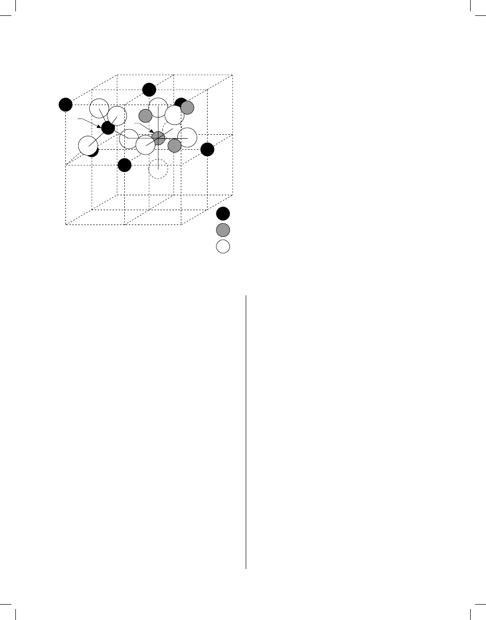
Spinel Structure (AB
2
O
4
)
A
B
A
B
O
2-
FIGURE 4. Arrangement of metal ions in the two octants A and B, show-
ing tetrahedrally (A) and octahedrally (B) coordinated sites. (Reprinted
from McCurrie, R.A., Ferromagnetic Materials, Academic Press, London,
1994. With permission.)
Selected Antiferromagnetic Solids
T
N
is the Néel temperature
Material
Structure
T
N
/K
Binary oxides
MnO
cub(fcc)
122
FeO
cub(fcc)
198
CoO
cub(fcc)
291
NiO
cub(fcc)
525
α-Mn
2
O
3
cub
90
CuO
monocl
230
UO
2
cub
30.8
Er
2
O
3
cub
3.4
Gd
2
O
3
cub
1.6
Perovskites
LaCrO
3
orth
282
LaMnO
3
orth
100
LaFeO
3
orth
750
NdCrO
3
orth
224
NdFeO
3
orth
760
YbCrO
3
orth
118
CaMnO
3
cub
110
EuTiO
3
cub
5.3
YCrO
3
orth
141
BiFeO
3
cub*
673
KCoF
3
cub
125
KMnF
3
cub*
88.3
KFeF
3
cub
115
KNiF
3
cub
275
NaMnF
3
cub*
60
NaNiF
3
orth
149
RbMnF
3
cub
82
Spinels
Co
3
O
4
cub
40
NiCr
2
O
4
tetr
65
Material
Structure
T
N
/K
ZnCr
2
O
4
cub
15
ZnFe
2
O
4
cub
9
GeFe
2
O
4
cub
10
MgV
2
O
4
cub
45
MnGa
2
O
4
cub
33
NiAs and related structures
CrAs
orth
300
CrSb
hex
705–723
CrSe
hex
300
MnTe
hex
320–323
NiS
hex
263
CrS
monocl
460
Rutile and related structures
CoF
2
tetr
38
CrF
2
monocl
53
FeF
2
tetr
79
MnF
2
tetr
67
NiF
2
tetr
83
CrCl
2
orth
20
MnO
2
tetr
84
FeOF
tetr
315
Corundum and related structures
Cr
2
O
3
rhomb
318
α-Fe
2
O
3
rhomb
948
FeTiO
3
rhomb
68
MnTiO
3
rhomb
41
CoTiO
3
rhomb
38
VF
3
and related structures
CoF
3
rhomb
460
CrF
3
rhomb
80
Properties of Magnetic Materials
12-107
Section 12.indb 107
4/28/05 1:57:39 PM

Material
Structure
T
N
/K
FeF
3
rhomb
394
MnF
3
monocl
43
MoF
3
rhomb
185
Miscellaneous
K
2
NiF
4
tetr
97
MnI
2
hex
3.4
CoUO
4
orth
12
CaMn
2
O
4
orth
225
CrN
cub*
273
CeC
2
tetr
33
FeSn
hex
373
Mn
2
P
hex
103
*
Distorted.
References
1. Gray, D. E., Ed., American Institute of Physics Handbook, Third
Edition, McGraw Hill, New York, 1972, p. 5–168 to 5–183.
2. Kittel, C., Introduction to Solid State Physics, 6th Edition, J. Wiley &
Sons, New York, 1986.
3. Ashcroft, N. W., and Mermin, N. D., Solid State Physics, Holt, Rinehart,
and Winston, New York, 1976, p. 697.
12-108
Properties of Magnetic Materials
Section 12.indb 108
4/28/05 1:57:39 PM
Wyszukiwarka
Podobne podstrony:
12 21 86
12 32 86
12 04 86
FM wyklad 12 20 01 2011
12 11 86
12 29 86
Wykład 2011-12-20, psychologia drugi rok, psychologia ról
12 34 86
12 38 86
12 06 86
12, F-20, Celem Cwiczenia jest poznanie fizycznych podstaw zjawiska termoelektrycznego i zapoznanie
12, F-20, Celem Cwiczenia jest poznanie fizycznych podstaw zjawiska termoelektrycznego i zapoznanie
12 20
06 OZE 2013 12 20 en
12 16 86
12 (20)
12 19 86
więcej podobnych podstron