
I wanted to learn more about the ADC on my ATMega128, so I dug into the docs and taught
myself a couple things. I thought since there wasn't a tutorial on this topic I'd write one. Hope
this helps someone out. Comments, clarifications and constructive criticism welcomed!
Newbie's Guide to the AVR ADC
Ken Worster
�
No part of this document is to be redistributed without the copyright holder's express
permission.
What is an ADC?
An ADC, or Analog to Digital Converter, allows one to convert an analog voltage to a digital
value that can be used by a microcontroller. There are many sources of analog signals that one
might like to measure. There are analog sensors available that measure temperature, light
intensity, distance, position, and force, just to name a few.
Introduction The AVR ADC
�
The AVR ADC allows the AVR microcontroller to convert analog voltages to digital values with
few to no external parts. The author wrote this tutorial with the ATMega128 in mind, though
other AVRs use similar hardware. The ADC built into the ATMega128 is capable of 10 bit
resolution. The ATMega128 microcontroller has 8 ADC channels, allowing up to 8 analog
sources to be attached to the microcontroller. The 8 ADC channels are connected to the internal
DAC through a device called a multiplexer. The multiplexer connects the 8 ADC channels (the 8
pins of Port F on the ATMega128) to the internal ADC. One channel at a time is passed through
the multiplexer to the ADC. The ADC has its own power supply, labeled AVCC, on the
ATMega128. This pin needs to be connected to a power source within .3 volts of the chip's VCC
supply. Most of the time, you would wire this to VCC. With the 10 bit DAC, this allows
measuring voltages from 0 to 5 volts with a resolution of 5/1024 volts, or 4.88 mV.
The ADC channels in the ATMega128 can be configured in several different ways. In this
tutorial, the channels are being used in single-ended mode. In this mode, the analog
�
�
voltages presented on the ADC channels are compared to ground. There are several selectable
voltage references, which determine the range of the ADC conversion. In this tutorial, AVCC is
used as the voltage reference. The ADC can also be set to run continuously (the free-running
mode) or to do only one conversion. The first example in this tutorial uses the free-running
mode to continuously update the ADC reading.
Part 1 A Simple Free-Running ADC Example
�
This example uses the simplest variable voltage source I could think of a potentiometer. I
�
wired up a 10k potentiometer on a breadboard as in the example below.
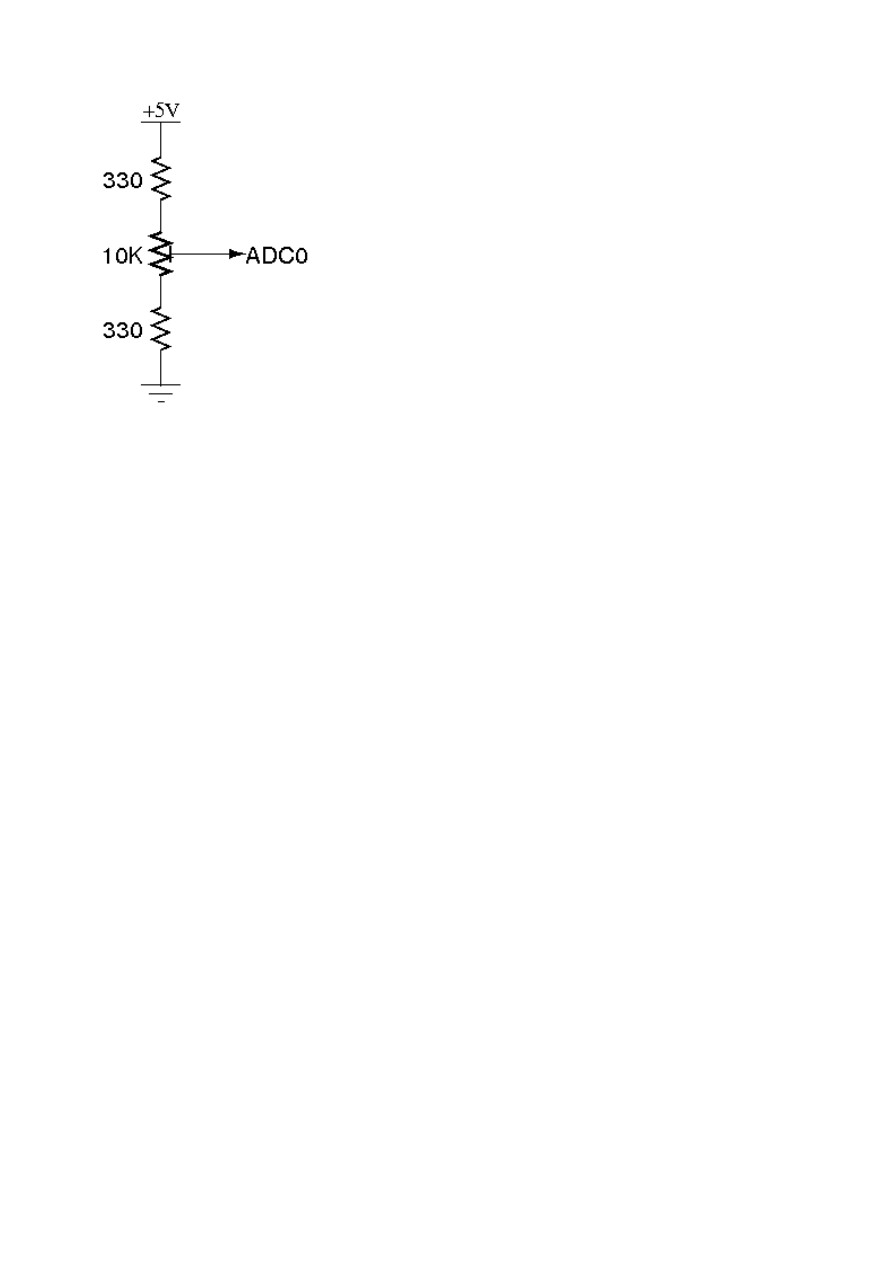
The two outside terminals were attached to 5 volts and ground, with the center terminal attached
to the first ADC channel. The two 330 ohm resistors protect the microcontroller pin from being
shorted to ground or to 5 volts at the edges of the potentiometer's travel. With this setup, turning
the potentiometer will give you a range of .15 volts to 4.85 volts between ground and ADC0. In
order to read the voltage of this circuit, its ground and the ground of the microcontroller need to
be connected.
To give an indication of the value the ADC is reading, two LEDs are hooked to the
microcontroller. We can toggle these to give us a high or low indication. Here is the
�
�
�
�
pseudocode for this example:
Code:
Set up output LEDs
Configure ADC Hardware
Enable ADC
Start A2D Conversions
WHILE Forever
IF ADC Value High, Turn on LED1
ELSE Turn on LED2
END WHILE
To simplify this example, we will set up the ADC to continuously measure the voltage on
ADC0. We will then poll the value in an endless loop and change the LEDs' statuses as we need
to. The skeleton code for our example would then be
Code:
#include <avr/io.h>
int main (void)
{
DDRE |= (1 << 2); // Set LED1 as output
DDRG |= (1 << 0); // Set LED2 as output

// TODO: Configure ADC Hardware
// TODO: Enable ADC
// TODO: Start A2D Conversions
for(;;) // Loop Forever
{
// TODO: Test ADC Value and set LEDs
}
}
Setting up the LEDs is outside the topic of this tutorial, so the code to set them up is shown
above without explanation. You can use any unused i/o line for the LEDs. Check out the
Programming 101 tutorial on the AVRFreaks forum for more information on this if you
�
�
need it.
The next step is to configure the ADC hardware. This is done through setting bits in the control
registers for the ADC. First, let's set the prescalar for the ADC. According to the datasheet, this
prescalar needs to be set so that the ADC input frequency is between 50 KHz and 200 KHz. The
ADC clock is derived from the system clock. With a system frequency of 16 MHz, a prescaler
of 128 will result in an ADC frequency of 125 Khz. The prescaling is set by the ADPS bits in
the ADCSRA register. According to the datasheet, all three ADPS bits must be set to get the 128
prescaler.
Code:
ADCSRA |= (1 << ADPS2) | (1 << ADPS1) | (1 << ADPS0);
Next, let's set the ADC reference voltage. This is controlled by the REFS bits in the ADMUX
register. The following sets the reference voltage to AVCC.
Code:
ADMUX |= (1 << REFS0);
To set the channel passed through the multiplexer to the ADC, the MUX bits in the ADMUX
register need to be set accordingly. Since we are using ADC0 here, which corresponds with all 5
MUX bits being zero, we don't need to set anything here.
In order to put the ADC into free-running mode, set the aptly-named ADFR bit in the ADCSRA
register:
Code:
ADCSRA |= (1 << ADFR);
One last settings change will be made to make reading the ADC value simpler. Though the ADC
has a resolution of 10 bits, this much information is often not necessary. This 10 bit value is split

across two 8 bit registers, ADCH and ADCL. By default, the lowest 8 bits of the ADC value are
found in ADCL, with the upper two being the lowest two bits of ADCH. By setting the ADLAR
bit in the ADMUX register, we can left align the ADC value. This puts the highest 8 bits of the
measurement in the ADCH register, with the rest in the ADCL register. If we then read the
ADCH register, we get an 8 bit value that represents our 0 to 5 volt measurement as a number
from 0 to 255. We're basically turning our 10 bit ADC measurement into an 8 bit one. Here's the
code to set the ADLAR bit:
Code:
ADMUX |= (1 << ADLAR);
That completes the setup of the ADC hardware for this example. Two more bits need to be set
before the ADC will start taking measurements. To enable the ADC, set the ADEN bit in
ADCSRA:
Code:
ADCSRA |= (1 << ADEN);
To start the ADC measurements, the ADSC bit in ADCSRA needs to be set:
Code:
ADCSRA |= (1 << ADSC);
At this point, the ADC would begin continuously sampling the voltage presented on ADC0. The
code to this point would look like this:
Code:
#include <avr/io.h>
int main (void)
{
DDRE |= (1 << 2); // Set LED1 as output
DDRG |= (1 << 0); // Set LED2 as output
ADCSRA |= (1 << ADPS2) | (1 << ADPS1) | (1 << ADPS0); // Set ADC prescalar to 128 -
125KHz sample rate @ 16MHz
ADMUX |= (1 << REFS0); // Set ADC reference to AVCC
ADMUX |= (1 << ADLAR); // Left adjust ADC result to allow easy 8 bit reading
// No MUX values needed to be changed to use ADC0
ADCSRA |= (1 << ADFR); // Set ADC to Free-Running Mode

ADCSRA |= (1 << ADEN); // Enable ADC
ADCSRA |= (1 << ADSC); // Start A2D Conversions
for(;;) // Loop Forever
{
// TODO: Test ADC Value and set LEDs
}
}
The only thing left to do is test the ADC value and set the LEDs to display a high / low
indication. Since the ADC reading in ADCH has a maximum value of 255, a test value of 128
was chosen to determine whether the voltage was high or low. A simple IF/ELSE statement in
the FOR loop will allow us to turn the correct LED on:
Code:
if(ADCH < 128)
{
PORTE |= (1 << 2); // Turn on LED1
PORTG &= ~(1 << 0); // Turn off LED2
}
else
{
PORTE &= ~(1 << 2); // Turn off LED1
PORTG |= (1 << 0); // Turn on LED2
}
Again, if the notation used above is unclear, the Programming 101 tutorial at AVRFreaks
�
�
forum gives a great explanation.
Here's the finished program with comments. When compiled and downloaded to an
ATMega128, LED1 will be lit for roughly half the rotation of the potentiometer, indicating a
low voltage reading. Near the halfway point of the potentiometer's rotation, LED1 will go
�
�
out and LED2 will light. Indicating a high voltage reading. By changing the tests in the
�
�
FOR loop, one could get different voltage indications with two or more LEDs.
Code:
#include <avr/io.h>
int main (void)
{
DDRE |= (1 << 2); // Set LED1 as output
DDRG |= (1 << 0); // Set LED2 as output
ADCSRA |= (1 << ADPS2) | (1 << ADPS1) | (1 << ADPS0); // Set ADC prescalar to 128 -
125KHz sample rate @ 16MHz

ADMUX |= (1 << REFS0); // Set ADC reference to AVCC
ADMUX |= (1 << ADLAR); // Left adjust ADC result to allow easy 8 bit reading
// No MUX values needed to be changed to use ADC0
ADCSRA |= (1 << ADFR); // Set ADC to Free-Running Mode
ADCSRA |= (1 << ADEN); // Enable ADC
ADCSRA |= (1 << ADSC); // Start A2D Conversions
for(;;) // Loop Forever
{
if(ADCH < 128)
{
PORTE |= (1 << 2); // Turn on LED1
PORTG &= ~(1 << 0); // Turn off LED2
}
else
{
PORTE &= ~(1 << 2); // Turn off LED1
PORTG |= (1 << 0); // Turn on LED2
}
}
}
Part 2 An Interrupt-Driven Example
�
Let's improve the first example so that we can run the LED IF loop in the background . It
�
�
takes 13 cycles of the ADC clock to perform one A2D conversion in free-running mode
according to the datasheet. With a prescaler of 128 as in the previous example, there are 13x128,
or 1664, system clock cycles between each A2D conversions. If our short IF loop can be run
only after an A2D conversion, this allows considerable processing time to be dedicated to other
tasks.
Microcontrollers allow this kind of program execution using something called interrupts.
Certain pieces of hardware within the microcontroller can signal that a certain task has been
completed. Normal program execution can be interrupted when one of these signals (the
�
�
interrupt) is asserted. Depending on the interrupt signal, different user-defined programs, called
interrupt service routines or ISRs, can be run. After the ISR completes, normal program
execution resumes.
The AVR ADC has an interrupt associated with it that is asserted when an A2D conversion
completes. There are several changes that need to make to the first example to utilize this
interrupt. First, let's write the ISR that will be run when the interrupt is asserted.
The first step in using interrupts in our application is to add the standard library header
avr/interrupt.h. This file defines functions and macros needed to utilize interrupts on the AVR.
The following line should be added below the io.h define in our original program.

Code:
#include <avr/interrupt.h>
Next, we'll define the ISR itself. To do this, we need the name of the interrupt we are connecting
to the ISR. Referring to the datasheet, we find the name of the interrupt we want to use ADC,
�
which is asserted when an A2C conversion completes. Here is the proper format for an ISR
using the ADC interrupt:
Code:
ISR(ADC_vect)
{
// Code to be executed when ISR fires
}
Now, we place the IF statement originally in the infinite loop inside the ISR, so it will only be
run when the ADC interrupt indicates a conversion has been completed:
Code:
ISR(ADC_vect)
{
if(ADCH < 128)
{
PORTE |= (1 << 2); // Turn on LED1
PORTG &= ~(1 << 0); // Turn off LED2
}
else
{
PORTE &= ~(1 << 2); // Turn off LED1
PORTG |= (1 << 0); // Turn on LED2
}
}
At this point, the program has an ISR defined. However, the ISR will never execute. Interrupts
on the AVR need to be enabled before they will run. This is done in two steps. First, the
interrupt capability of the microprocessor needs to be enabled. This is done with the sei()
function call, defined in interrupt.h to simplify this process. Next, the ADC interrupt needs to be
enabled. This is done by setting the ADIE bit in the ADCSRA register. The following two lines
enable the ADC interrupt:
Code:
ADCSRA |= (1 << ADIE);
sei();

We can now combine the new interrupt code with our first example. We will insert the ISR after
the main loop. The interrupt enable lines will be inserted before we start the A2D conversions.
The FOR loop is now empty, as the code we had there originally has been moved to the ISR.
Other code could be inserted here to run between ISR calls. The full code is shown below.
Code:
#include <avr/io.h>
#include <avr/interrupt.h>
int main (void)
{
DDRE |= (1 << 2); // Set LED1 as output
DDRG |= (1 << 0); // Set LED2 as output
ADCSRA |= (1 << ADPS2) | (1 << ADPS1) | (1 << ADPS0); // Set ADC prescaler to 128 -
125KHz sample rate @ 16MHz
ADMUX |= (1 << REFS0); // Set ADC reference to AVCC
ADMUX |= (1 << ADLAR); // Left adjust ADC result to allow easy 8 bit reading
// No MUX values needed to be changed to use ADC0
ADCSRA |= (1 << ADFR); // Set ADC to Free-Running Mode
ADCSRA |= (1 << ADEN); // Enable ADC
ADCSRA |= (1 << ADIE); // Enable ADC Interrupt
sei(); // Enable Global Interrupts
ADCSRA |= (1 << ADSC); // Start A2D Conversions
for(;;) // Loop Forever
{
}
}
ISR(ADC_vect)
{
if(ADCH < 128)
{
PORTE |= (1 << 2); // Turn on LED1
PORTG &= ~(1 << 0); // Turn off LED2
}
else
{
PORTE &= ~(1 << 2); // Turn off LED1
PORTG |= (1 << 0); // Turn on LED2
}
}

Last edited by penquissciguy on Nov 17, 2007 - 06:53 AM; edited 1 time in total
Wyszukiwarka
Podobne podstrony:
Newbie s Guide to the AVR ADC
Newbie s Guide to AVR Interrupts
Newbie s Guide to AVR Timers
Guide to the properties and uses of detergents in biology and biochemistry
A Guide to the Law and Courts in the Empire
Jouni Yrjola Easy Guide to the Classical Sicilian (feat Richter Rauzer and Sozin Attacks)
Players Guide to the Sabbat (Text Only) 1992
Guide to the installation of PV systems 2nd Edition
Guide to the Gods A fuller and more detailed list of Asatru heathen deities
Guide to the properties and uses of detergents in biology and biochemistry
A Guide to the Law and Courts in the Empire
Beginners Introduction to the AVR ASM
Guide to the Picatrix
Guide to the Names in The Lord J R R Tolkien
Jouni Yrjola Easy Guide to the Classical Sicilian (feat Richter Rauzer and Sozin Attacks)
Narratology A Guide to the Theory of Narrative
więcej podobnych podstron