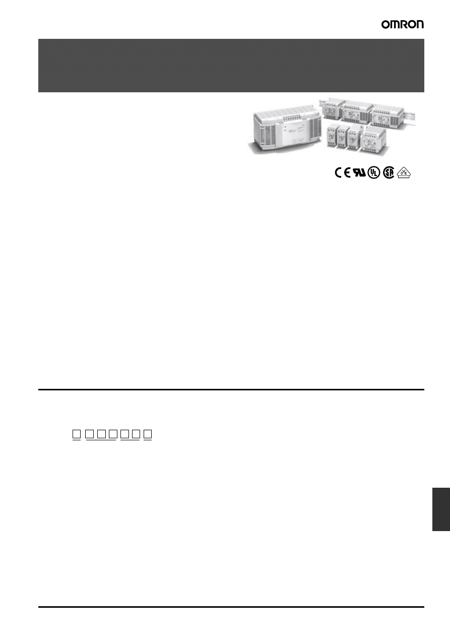
Switch mode Power Supply
S82K
L-5
Power
Supplies
Switch mode Power Supply
S82K
Ultimate DIN-track-mounting Power Supply
with a Wide Power Range from 3 to 240 W
• Wide power range: 3 to 240 W
• Wide AC input voltage range: 100 to 240 V on one body.
• Undervoltage alarm function (indicator) incorporated as stan-
dard. (With the 240-W models, applicable only to the “-T” mod-
els.) 90 and 100-W models standardized with the alarm output.
• Output/input terminal parts separated on body upper/bottom
side, respectively, for safe and smart wiring.
• Multiple pairs of output terminals;
Three pairs for 90, 100, and 240-W models
Two pairs for 30 and 50-W models
• Finger-safe terminal block with cover according to VDE0106/
P100.
• Conforms to the stringent EN50081-1 standard for universal
use in any environment subject to EMI conditions (except for
240-W models) in addition to EN50082-2 conformity for use at
any EMS environment.
• DC output ports comply to EN55022 class A, thus ensuring use
in any environment subject to EMI with recommended external
filters (3- to 100-W models).
• Meets EN61000-3-2 (limits for harmonic current emissions) with
PFC on 90, 100, and 240-W models.
• Parallel running operation (100 and 240-W models).
• Class 2 approved (except for 240-W models and 7.5-W dual
output models).
• Approvals of various international safety standards for industrial
control equipment and industrial computing systems (ITE/TE),
in addition to other important approvals.
• Six-language instruction manual provided.
Model Number Structure
■ Model Number Legend
S82K -
1
2
3
4
1. Power Factor Correction
None: No
P:
Yes
3. Output Voltage
05: +5 VDC
12: +12 VDC
15: +15 VDC
24: +24 VDC
27:
±12 VDC
28:
±15 VDC
2. Power Ratings
003: 3
W
007: 7.5 W
015: 15 W
030: 30
W
050: 50 W
090: 90 W
4. Undervoltage alarm indicator/output
<For 3- to 100-W models>
None: Yes
<For 240-W models>
L-6
Switch mode Power Supply
S82K
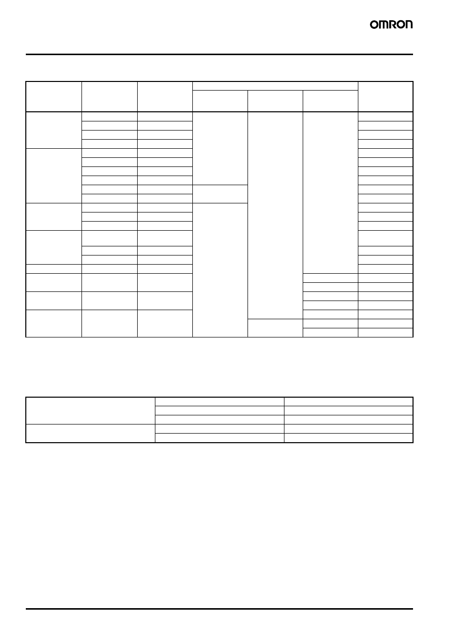
Ordering Information
■ List of Models
Note: 1. The output capacity of the S82K-03005 is 25 W.
2. The output current during parallel operation is 3.78 A.
3. The output current during parallel operation is 9 A.
4. Comply to EN61000-3-2 A14
■ Accessories (Order Separately)
Power ratings
Output voltage
Output current
Function Configuration
Models
Output
Undervoltage
alarm indicator/
output
PFC
3 W
5 V
0.6 A
Single output
Yes
No
S82K-00305
12 V
0.25 A
S82K-00312
15 V
0.2 A
S82K-00315
24 V
0.13 A
S82K-00324
7.5 W
5 V
1.5 A
S82K-00705
12 V
0.6 A
S82K-00712
15 V
0.5 A
S82K-00715
24 V
0.3 A
S82K-00724
+V12/
−V12
0.3 A/0.2 A
Dual output
S82K-00727
+V15/
−V15
0.2 A/0.2 A
S82K-00728
15 W
5 V
2.5 A
Single output
S82K-01505
12 V
1.2 A
S82K-01512
24 V
0.6 A
S82K-01524
30 W
5 V
5.0 A
S82K-03005
(see note 1)
12 V
2.5 A
S82K-03012
24 V
1.3 A
S82K-03024
50 W
24 V
2.1 A
S82K-05024
90 W
24 V
3.75 A
Yes
S82K-P09024
No (see note 4)
S82K-09024
100 W
24 V
4.2 A
(see note 2)
Yes
S82K-P10024
No (see note 4)
S82K-10024
240 W
24 V
10 A
(see note 3)
No
S82K-24024T
No
Yes
S82K-P24024
No
S82K-24024
Mounting Track
50 cm (l)
× 7.3 mm (t)
PFP-50N
1 m (l)
× 7.3 mm (t)
PFP-100N
1 m (l)
× 16 mm (t)
PFP-100N2
Noise Filter
for 3- to 50-W models
S82Y-JF3-N
for 90-W and 100-W models
S82Y-JF6-N
Switch mode Power Supply
S82K
L-7
Power
Supplies
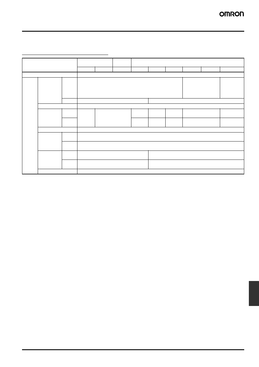
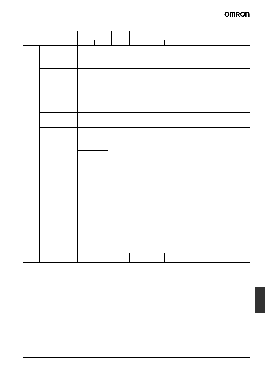
Specifications
■ Ratings/Characteristics
3- to 240-W models without PFC
Note: 1. Use with DC voltage input is beyond the conditions of approval or conformance to applicable safety standards.
2. Use the 7.5-W single-output models under the load of 90% max. if the voltage range is between 90 and 110 VDC.
3. Defined with a 100% load and the rated input voltage (100 or 200 VAC).
Item
Single output
Dual
outputs
Single output
3 W
7.5 W
7.5 W
15 W
30 W
50 W
90 W
100 W
240 W
Efficiency (typical)
60% to 80% (Varies depending on specifications.)
Input
Voltage
(see note 1)
AC
100 to 240 V (85 to 264 V)
100 V (85 to 132 V)/
200 V (170 to 264 V)
Selectable
100 V (85 to
132 V)/
200 V (170 to
253 V)
Selectable
DC
90 to 350 V (see note 2)
Not possible
Frequency
50/60 Hz (47 to 450 Hz)
Current
(see note 3)
100-V
input
0.15 A
max.
0.25 A max.
0.45 A
max.
0.9 A
max.
1.3 A
max.
2.5 A max.
5.5 A max.
200-V
input
0.25 A
max.
0.6 A
max.
0.8 A
max.
1.5 A max.
3.5 A max.
Power factor
---
Leakage cur-
rent
(see note 3)
100-V
input
0.5 mA max.
200-V
input
1 mA max.
Inrush cur-
rent
(see note 3)
100-V
input
15 A max.
25 A max.
200-V
input
30 A max.
50 A max.
Noise filter
Yes
L-8
Switch mode Power Supply
S82K
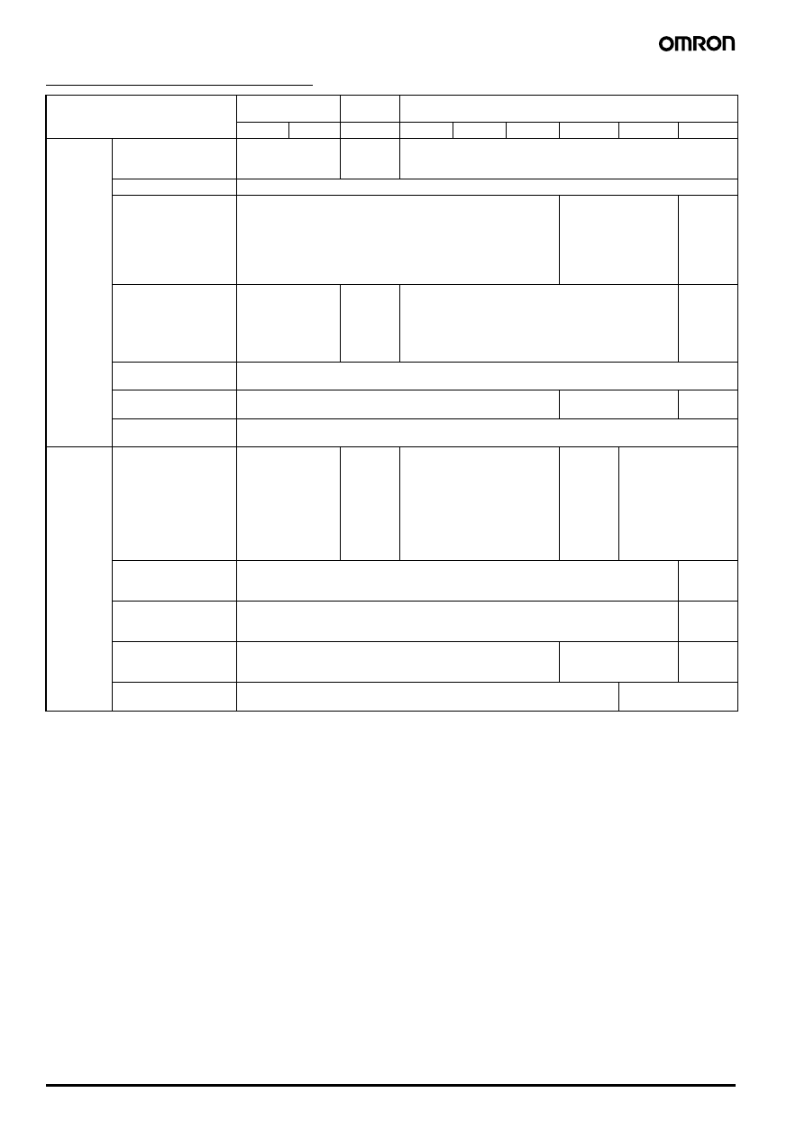
3- to 240-W models without PFC
Note: 1. Defined with a 100% load and the rated input voltage (100 or 200 VAC).
2. The output specification is defined at the power supply output terminals.
3. The settings for the output voltage must be within the following range:
+V:
±1% of the rated value
−V: ±5% of the rated value
4. When using the 7.5-W single-output models within the input voltage range between 90 and 110 VDC, the protection function will operate
at a current of 95% to 160% of the rated load current.
5. When the ambient temperature exceeds 25
°C, the protection function will operate at a current of 92% to 111% of the rated load current.
6. Circuit-breaker type. To reset, turn the input power supply OFF, then after 1 min has elapsed, turn the input power supply ON again.
7. Parallel operation is set with the Parallel/Single Operation Selector Switch. (This setting is not required for S82K-10024 models.)
Item
Single output
Dual
outputs
Single output
3 W
7.5 W
7.5 W
15 W
30 W
50 W
90 W
100 W
240 W
Output
(see note 2)
Voltage adjustment
range
±10% (V.ADJ)
Not possi-
ble (see
note 3)
±10% (V.ADJ); −10% to 15% for S82K-03012/-03024/-05024
Ripple (see note 1)
2% (p-p) max.
Input variation
influence
0.5% max. (at 85 to 264 VAC input, 100% load)
0.5% max. (at 85 to
132 VAC/170 to
264 VAC input, 100%
load)
0.5% max.
(at 85 to
132 VAC/
170 to
253 VAC
input,
100% load)
Load variation
influence
1.5% max.
(0 to 100% load)
+V: 1.5%
max.
−V: 3%
max.
(0 to 100%
load)
1.5% max.
(0 to 100% load)
1.5% max.
(10 to
100% load)
Temperature variation
influence (see note 1)
0.05%/
°C max.
Start up time
100 ms max. (up to 90% of output voltage at rated input and output) 200 ms max.
300 ms
max.
Hold time
(see note 1)
20 ms min.
Additional
function
Overload protection
105% to 160% of
rated load current,
inverted L drop,
automatic reset
(see note 4)
105% to
250% of
rated load
current, in-
verted L
drop, auto-
matic reset
105% to 160% of rated load cur-
rent, inverted L drop, automatic
reset
(30-W, 50-W models: inverted L
drop, intermittent, automatic re-
set)
101% to
111% of
rated load
current, in-
verted L
drop, auto-
matic re-
set (see
note 5)
105% to 160% of rated
load current, inverted L
drop, automatic reset
Overvoltage
protection (see note 6)
No
S82K-
24024T
model only
Undervoltage alarm
indicator (DC LOW
indicator)
Yes (color: red)
S82K-
24024T
model only
Undervoltage alarm
output (DC LOW
output)
No
Yes
S82K-
24024T
model only
Parallel operation
Impossible
Possible (2 units max.)
(see note 7)
Switch mode Power Supply
S82K
L-9
Power
Supplies
3- to 240-W models without PFC
Note: 1. Defined with a 100% load and the rated input voltage (100 or 200 VAC).
2. Do not press down on the terminal block with a force exceeding 75 N while tightening the terminals.
3. To ensure the emission ratings, a noise filter should be used on the output lines at the closest point.
(3- to 50-W models: S82Y-JF3-N, 90- and 100-W models: S82Y-JF6-N)
4. Models other than dual output models satisfy the Class-2 requirements.
5. To meet Class-2 requirements with the 100-W model, either a fuse or circuit breaker that is UL listed or CSA certified, and rated at 4.2 A
max. should be wired in series with the load to be connected to the power supply. Only then can the power supply output be considered
as meeting Class 2.
Item
Single output
Dual
outputs
Single output
3 W
7.5 W
7.5 W
15 W
30 W
50 W
90 W
100 W
240 W
Other
Ambient temperature Operating: See the derating curve in the Engineering Data section
(no condensation or icing)
Storage:
−25°C to 65°C (no condensation or icing)
Ambient humidity
Operating: 25% to 85%
Storage:
25% to 90%
Dielectric strength
3,000 VAC at 50/60 Hz for 1 min (between all inputs and outputs)
2,000 VAC at 50/60 Hz for 1 min (between all inputs and GR terminal)
1,000 VAC at 50/60 Hz for 1 min (between all outputs and GR terminal)
Alarm current: 10 mA (3- to 7.5-W models) 20 mA (15- to 100-W models) 25 mA (240-W models)
Insulation resistance 100 M
Ω min. at 500 VDC (between all outputs and all inputs/GR terminal)
Vibration resistance
Malfunction: 10 to 55 Hz, 0.375-mm single amplitude for 2 hrs each in X, Y, and
Z directions
Malfunction: 10 to
55 Hz, 0.15-mm
single amplitude
for 2 hrs each in X,
Y, and Z directions
Shock resistance
Malfunction: 300 m/s
2
, 3 times each in
±X, ±Y, and ±Z directions
Screw tightening
torque
0.74 N • m max. (see note 2)
Output indicator
Yes (green)
Electromagnetic
interference
(see note 1)
Conforms to FCC class B
Conforms to FCC class A
EMC
(see note 3)
3 to 100-W Models
(EMI):
EN50081-1
Emission Enclosure:
EN55022 class B (equivalent to EN55011 class B)
Emission AC Mains:
EN55022 class B (equivalent to EN55011 class B)
Emission Output Ports: EN55022 class A (with a recommended optional filter) (see note 3)
240-W Models
(EMI):
EN50081-2
Emission Enclosure:
EN55011 class A
Emission AC Mains:
EN55011 class A
Common to All Models
(EMS):
EN50082-2
Immunity ESD:
EN61000-4-2: 4-kV contact discharge (level 2)
8-kV air discharge (level 3)
Immunity Burst:
EN61000-4-4: 2-kV power-line (level 3)
2-kV output line (level 4)
Immunity Surge:
EN61000-4-5: between 2-kV lines (except for 240-W models)
between 4-kV line and FG (except for 240-W models)
Approved standards
Class 2 (UL 1310)/Class 2 (CSA C22.2 No. 950) (see notes 4 and 5)
UL 508 (Listing)/1950
CSA C22.2 No.14/No.950, EN50178 (VDE0160), EN60950
Conforms to VDE0106/P100
UL 508 (Listing)/
1012
CSA C22.2 No.14,
CSA E.B. 1402C,
EN50178
(VDE0160),
EN60950
Conforms to
VDE0106/P100
Weight
150 g max.
260 g
max.
380 g
max.
400 g
max.
600 g max.
1,800 g max.
L-10
Switch mode Power Supply
S82K
90-/100-/240W models with PFC (S82K-P
@@@24 models)
Note: 1. Defined with a 100% load and the rated input voltage (100 or 200 VAC)
2. The output specification is defined at the power supply output terminals.
3. When the ambient temperature exceeds 25
°C, the protection function will operate at a current of 92% to 111% of the rated load current.
4. Parallel operation is set with the Parallel/Single Operation Selector Switch.
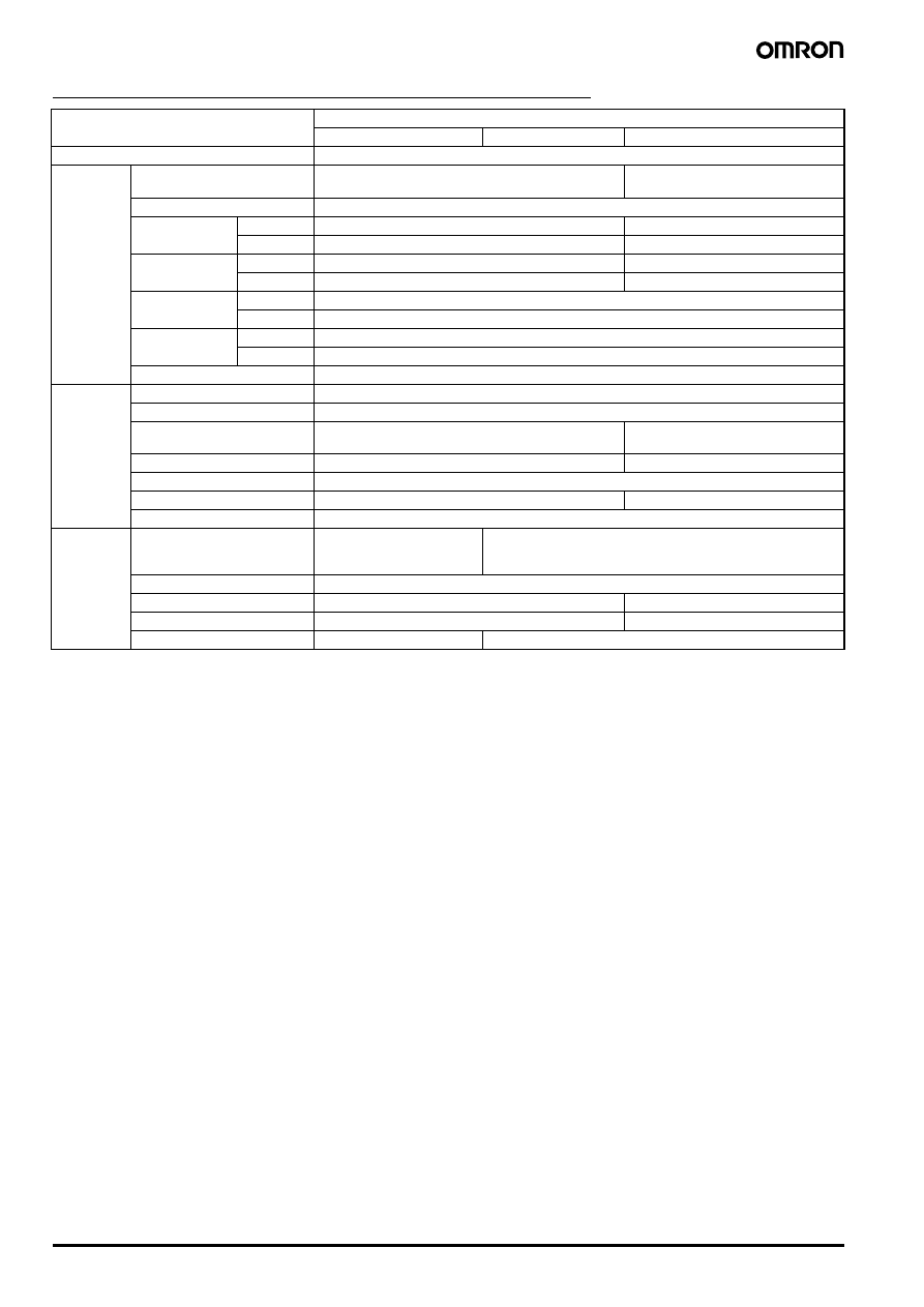
Item
Single output
90 W
100 W
240 W
Efficiency (typical)
60% to 80% (Varies depending on specifications.)
Input
Voltage
100 V (85 to 132 VAC)/200 V (170 to 264 VAC) Select-
able
100 to 230 V (85 to 253 VAC)
Frequency
50/60 Hz (47 to 63 Hz)
Current
(see note 1)
100-V input 2.5 A max.
4 A max.
200-V input 1.0 A max.
2 A max.
Power factor
100-V input ---
0.95 min.
200-V input 0.7 min.
0.95 min.
Leakage current
(see note 1)
100-V input 0.5 mA max.
200-V input 1 mA max.
Inrush current
(see note 1)
100-V input 25 A max.
200-V input 50 A max.
Noise filter
Yes
Output
(see note 2)
Voltage adjustment range
±10% (V.ADJ)
Ripple (see note 1)
2% (p-p) max.
Input variation influence
0.5% max. (at 85 to 132 VAC/170 to 264 VAC input,
100% load)
0.5% max. (at 85 to 253 VAC input,
100% load)
Load variation influence
1.5% max. (0 to 100% load)
1.5% max. (10 to 100% load)
Temperature variation
0.05%/
°C max.
Startup time
200 ms max.
1,000 ms max.
Hold time (see note 1)
20 ms min.
Additional
function
Overload protection
101% to 111% of rated load
current, inverted L drop, auto-
matic reset (see note 3)
105% to 160% of rated load current, inverted L drop, automatic re-
set
Overvoltage protection
No
Under voltage alarm indicator Yes (color: red)
No
Under voltage alarm output
Yes
No
Parallel operation
Impossible
Possible (2 units max.) (see note 4)
Switch mode Power Supply
S82K
L-11
Power
Supplies
90-/100-/240W models with PFC (S82K-P
@@@24 models)
Note: 1. Defined with a 100% load and the rated input voltage (100 or 200 VAC)
2. Do not press down on the terminal block with a force exceeding 75 N while tightening the terminals.
3. To ensure the Emission Enclosure ratings, a noise filter should be used on the output lines at the closest point. (90- and 100-W models:
S82Y-JF6-N)
4. To ensure the Emission Enclosure rating, a ferrite ring core should be used on all cables.
5. To meet Class-2 requirements with the 100-W model, either a fuse or circuit breaker that is UL listed or CSA certified, and rated at 4.2 A
max. should be wired in series with the load to be connected to the power supply. Only then can the power supply output be considered
as meeting Class 2.
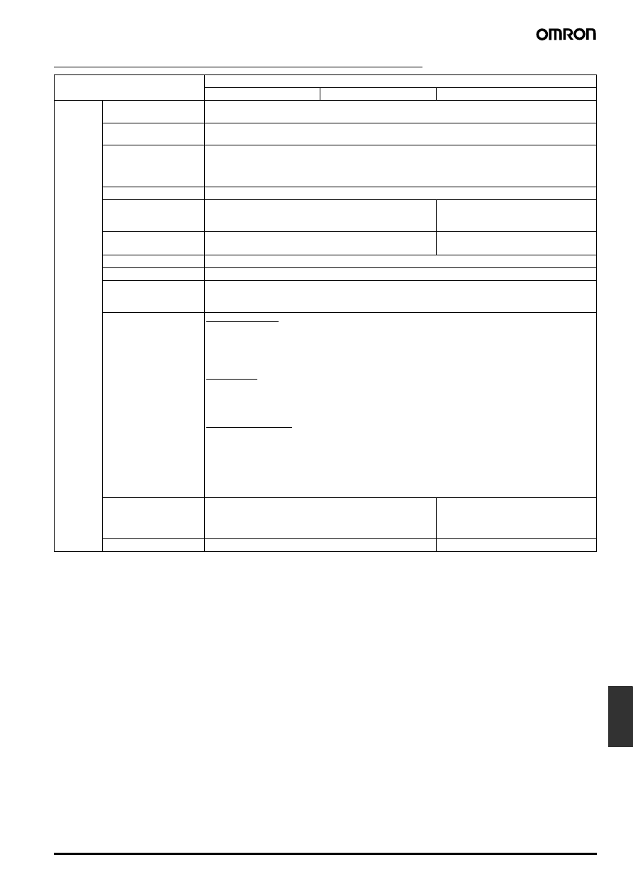
Item
Single output
90 W
100 W
240 W
Other
Ambient temperature
Operating: See the derating curve in the Engineering Data section (No condensation or icing)
Storage:
−25°C to 65°C (no condensation or icing)
Ambient humidity
Operating: 25% to 85%
Storage:
25% to 90%
Dielectric strength
3,000 VAC at 50/60 Hz for 1 min. (between all inputs and outputs)
2,000 VAC at 50/60 Hz for 1 min. (between all inputs and GR terminal)
1,000 VAC at 50/60 Hz for 1 min. (between all outputs and GR terminal)
Alarm current: 20 mA (90- and 100-W models) 25 mA (240-W models)
Insulation resistance
100 M
Ω min. at 500 VDC (between all outputs and all inputs/GR terminal)
Vibration resistance
Malfunction: 10 to 55 Hz, 0.375-mm single amplitude for 2
hrs each in X, Y, and Z directions
Malfunction: 10 to 55 Hz, 0.15-mm single
amplitude for 2 hrs each in
X, Y, and Z directions
Shock resistance
Malfunction: 150 m/s
2
, 3 times each in
±X, ±Y, and ±Z direc-
tions
Malfunction: 300 m/s
2
, 3 times each in
±X, ±Y, and ±Z directions
Screw tightening torque 0.74 N • m max. (see note 2)
Output indicator
Yes (Green)
Electromagnetic inter-
ference
(see note 1)
Conforms to FCC class A
EMC (see note 3, 4)
90-, 100-W Models
(EMI):
EN50081-1
Harmonic Current:
EN61000-3-2 (200 VAC input only)
Emission Enclosure:
EN55022 class B
Emission AC Mains:
EN55022 class B
Emission Output Ports: EN55022 class A (with a recommended optional filter) (see note 3)
240-W Model
(EMI):
EN50081-2
Harmonic Current:
EN61000-3-2
Emission Enclosure:
EN55011 class A (see note 4)
Emission AC Mains:
EN55011 class A
Common to All Models
(EMS):
EN50082-2
Immunity ESD:
EN61000-4-2: 4-kV contact discharge (level 2)
8-kV air discharge (level 3)
Immunity Burst:
EN61000-4-4: 2-kV power-line (level 3)
2-kV output line (level 4)
Immunity Surge:
EN61000-4-5: between 2-kV lines (except for 240-W models)
between 4-kV line and FG (except for 240-W models)
Approved standards
Class 2 (UL1310)/Class 2 (CSA C22.2 No. 950) (see note 5)
UL508 (Listing)/1950
CSA C22.2 No. 14/No. 950, EN50178 (VDE0160), EN60950
Conforms to VDE0106/P100
UL508 (Listing)/1012
CSA C22.2 No. 14/E.B. 1402C, EN50178
(VDE0160), EN60950, Conforms to
VDE0106/P100
Weight
1,000 g max.
2,200 g max.
L-12
Switch mode Power Supply
S82K
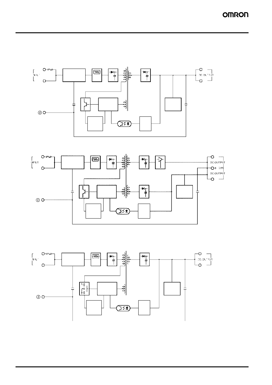
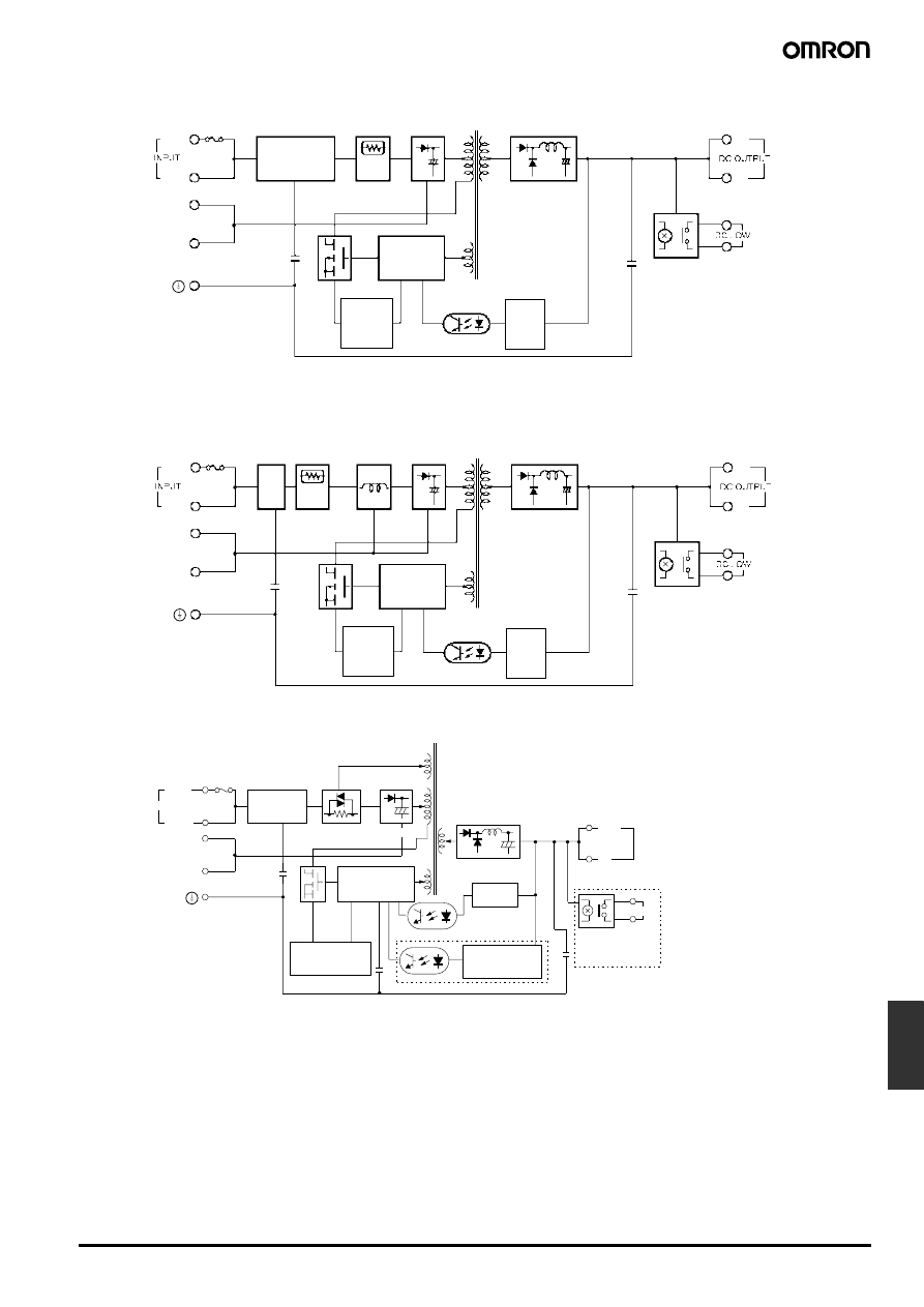
Connections
■ Block Diagrams
AC (L)
AC (N)
− V
+ V
Fuse (1 A)
Noise filter
Inrush current
protection circuit
Rectifier
Photocoupler
Rectifier
Detector
Undervoltage
alarm
indicator
Drive control
circuit
Overload
alarm
circuit
S82K-003
@@ (3 W)
S82K-007
@@ (7.5 W, Single Output)
AC (L)
AC (N)
− V
+ V
S82K-007
@@ (7.5 W, Dual Outputs)
Fuse (1 A)
Noise filter
Rectifier
Photocoupler
Rectifier
Rectifier
Detector
Undervoltage
alarm
indicator
3-terminal
REG
Drive control
circuit
Overload
alarm
circuit
Inrush current
protection circuit
AC (L)
AC (N)
− V
+ V
Fuse (3 A)
Noise filter
Rectifier
Photocoupler
Rectifier
Detector
S82K-015
@@ (15 W)
S82K-030
@@ (30 W)
S82K-05024 (50 W)
Inrush current
protection circuit
Drive control
circuit
Overload
alarm
circuit
Undervoltage
alarm
indicator
Switch mode Power Supply
S82K
L-13
Power
Supplies
AC (L)
AC (N)
− V
+ V
Fuse (5 A)
Noise filter
Rectifier
Photocoupler
Rectifier
Detector
S82K-09024 (90 W)
S82K-10024 (100 W)
100 or 200 V
Selectable
terminals
(see note)
Inrush current
protection circuit
Drive control
circuit
Overload
alarm
circuit
Note: Use the short bar to short-circuit terminals 7 and 8 to select 100 to 120 VAC and
remove the short bar to select 200 to 240 VAC.
Undervoltage
alarm indicator
AC (L)
AC (N)
− V
+ V
Fuse (5 A)
Noise
filter
Rectifier
Photocoupler
Rectifier
Detector
S82K-P09024 (90 W)
S82K-P10024 (100 W)
100 or 200 V
Selectable
terminals
(see note)
Inrush current
protection circuit
Harmonic current
emission control
(200-V input only)
Drive control
circuit
Overload
alarm
circuit
Note: Use the short bar to short-circuit terminals 7 and 8 to select 100 to 120 VAC and
remove the short bar to select 200 to 240 VAC.
Undervoltage
alarm indicator
− V
+ V
AC (L)
AC (N)
S82K-24024
@ (240 W)
Fuse (5 A)
Noise filter
Overvoltage protection circuitry (see note 1)
Photocoupler
INPUT
Rectifier
Detector
Rectifier
DC LOW
(see note 1)
100 or 200 V
Selectable
terminals
(see note 2)
Inrush current
protection circuit
Drive control
circuit
Overload alarm
circuit
Overvoltage
alarm circuit
DC
OUTPUT
Undervoltage
alarm
indicator/output
Note: 1. The overvoltage protection circuitry and undervoltage alarm indicator are available
in the S82K-24024T only.
2. Use the short bar to short-circuit terminals 7 and 8 to select 100 to 120 VAC and
remove the short bar to select 200 to 230 VAC.
L-14
Switch mode Power Supply
S82K
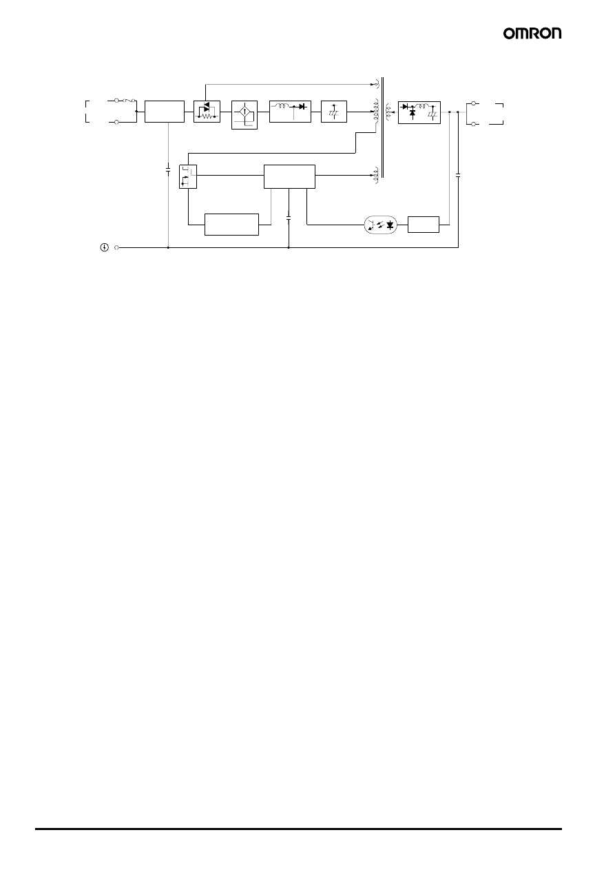
− V
+ V
AC (L)
AC (N)
S82K-P24024 (240 W)
Fuse (8 A)
Noise filter
INPUT
Detector
Rectifier
Smoothing
Photocoupler
Rectifier
Inrush current
protection circuit
Harmonic current
emission control
Drive control
circuit
Overload alarm
circuit
DC
OUTPUT
Switch mode Power Supply
S82K
L-15
Power
Supplies
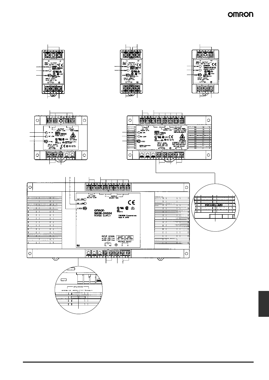
■ Installation
8
2
3
4
9
6 7 5
6
7
5
1
2
3
1
1
2
3
7
5
6
7
5
1
2
3
1
1
5
7
6
2
3
1
8
5
7
6
2
3
4
9
S82K-015
@@
S82K-030
@@/S82K-05024
S82K-
@09024/S82K-@10024
S82K-
@24024@
Bottom view
S82K-007
@@ (Dual outputs)
S82K-003
@@/S82K-007@@
(Single Output)
Bottom view
(Only for S82K-
P10024)
1. DC Output Terminals: Connect the load lines to these terminals.
2. Input Terminals: Connect the input lines to these terminals.
3. Ground Terminal (GR): Connect a ground line to this terminal.
4. Input Voltage Selector Terminals: Selects a 100 V or 200 V input voltage.
5. Output Indicator (DC ON): Lights while a Direct Current (DC) output is ON.
6. Output Voltage Adjuster(V.ADJ): It is possible to increase or decrease the
output voltage.
7. Undervoltage Alarm Indicator (DC LOW): Other than S82K-24024 and
S82K-P24024 models.
8. Undervoltage Alarm Output (DC LOW): S82K-
@09024/-@10024/-24024T
models only.
9. Parallel/Single Operation Selector: Set to "PARALLEL" or "P" for parallel
operation.
L-16
Switch mode Power Supply
S82K
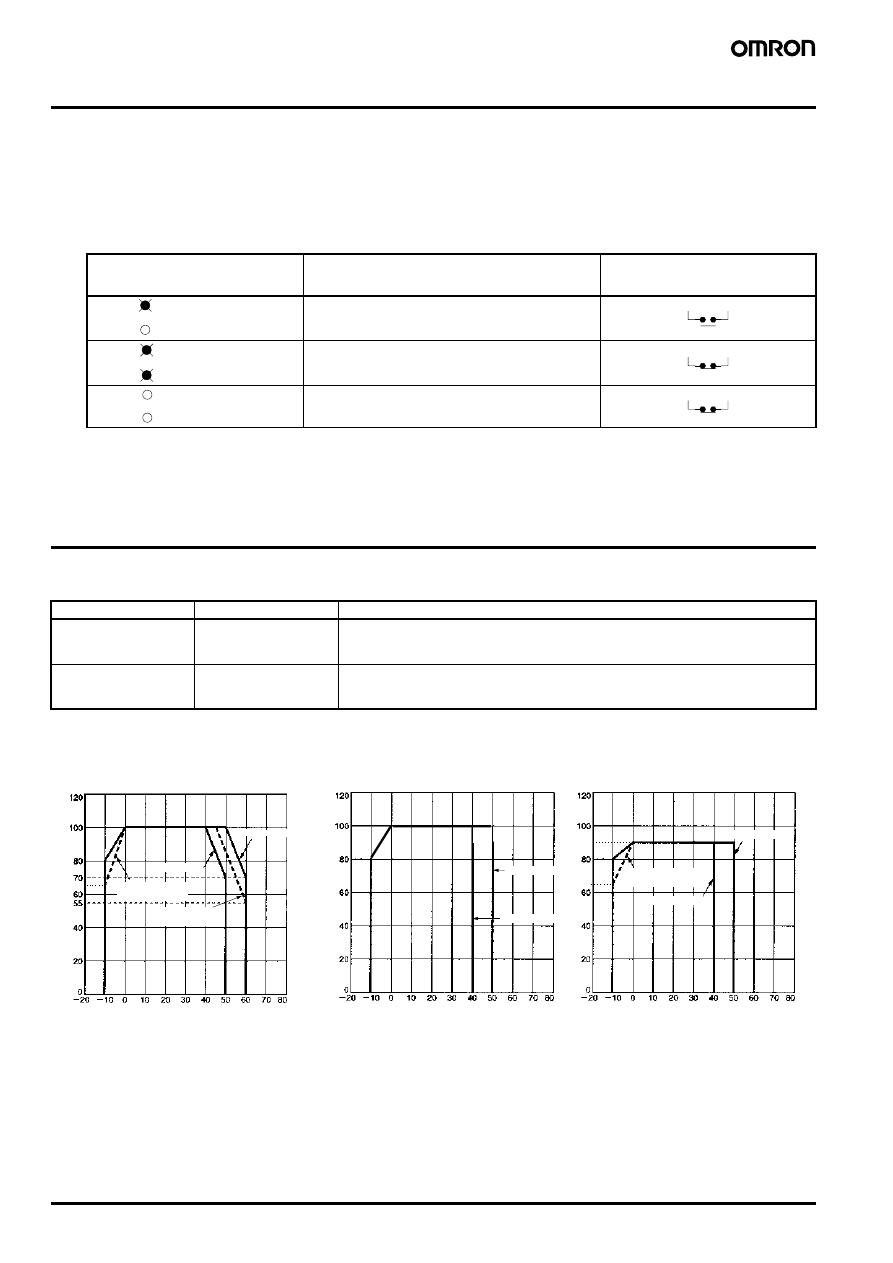
Operation
■ Undervoltage Alarm Indicator and Output Function
(All Models Except for S82K-24024/P24024)
If the output voltage at the output terminal drops to 75% to 90% of the rated voltage, the red indicator of the S82K (DC LOW indicator) will be lit.
In the case of the S82K-
@09024/@10024/24024T, a voltage drop alarm will be output via the relay available in the models (DC LOW output).
Note: This function detects the voltage at the output terminal of the Power Supply. To check the precise output voltage, measure the voltage at the
terminal of the load.
Note: 1. The more the voltage at the output terminal drops, the darker both the green and red indicators will be.
2. The relay contacts have a capacity of 0.1 A at 24 VDC.
3. The red indicator will actually first light at a voltage between 75% and 90% of the rated voltage.
Engineering Data
■ Reference Value
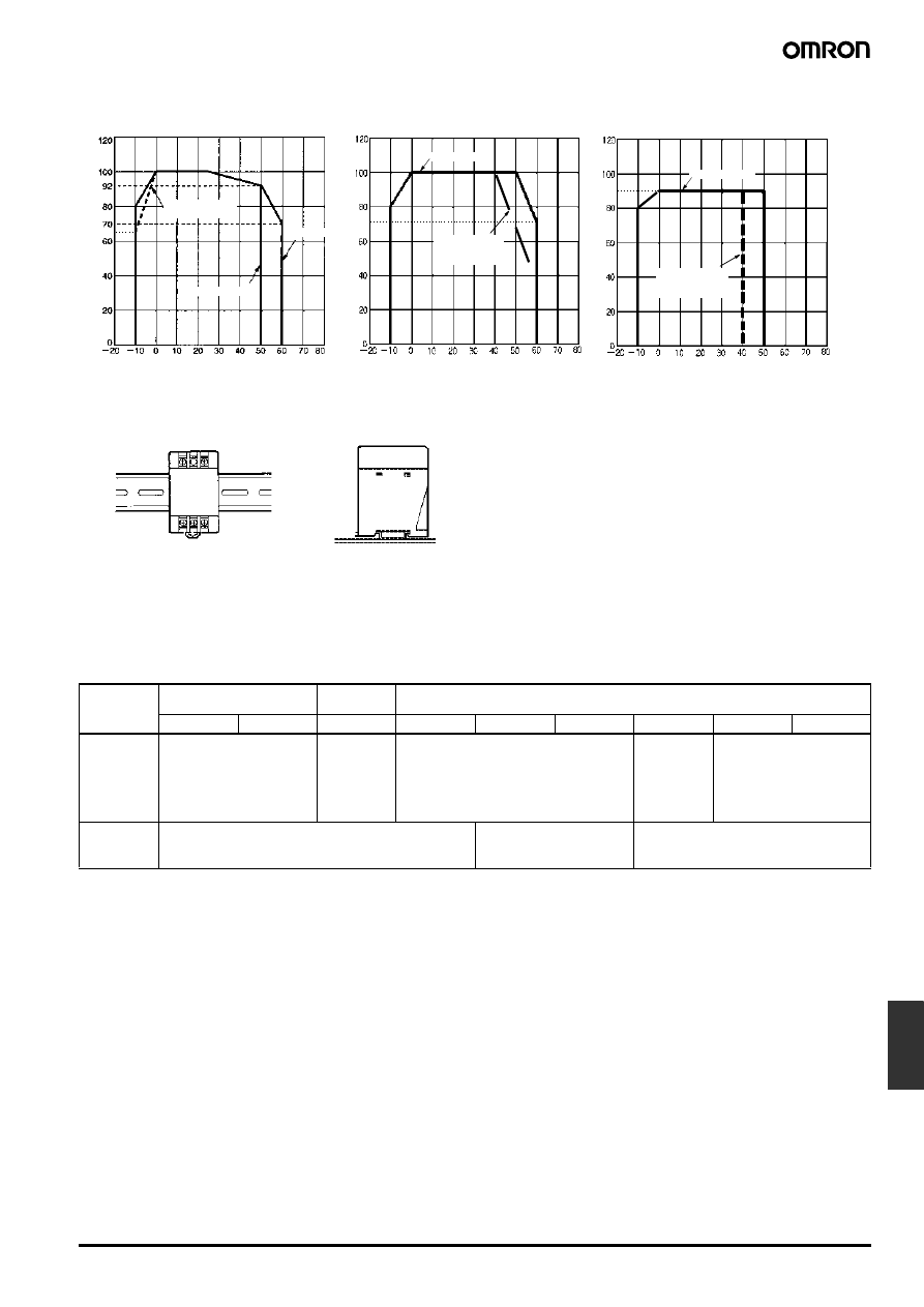
■ Derating Curve
Indicator
Voltage
Operation of
@09024/@10024/
24024T’s output (DC LOW output)
(see note 2)
If the voltage at the output terminal is more than 82% of
the rated voltage and operation is normal, the green in-
dicator will be lit and the red indicator will not be lit.
If the voltage at the output terminal drops to below 82%
of the rated voltage, the red indicator will be lit. (See
note 3.)
If the voltage at the output terminal approaches 0 V,
both the green and red indicators will not be lit.
Green: DC
ON
Red: DC
LOW
Green: DC
ON
Red: DC
LOW
(see note 1)
Green: DC
ON
Red: DC
LOW
Item
Value
Definition
Reliability (MTBF)
135,000 hrs min.
MTBF stands for Mean Time Between Failures, which is calculated according to the prob-
ability of accidental device failures, and indicates reliability of devices. Therefore, it does
not necessarily represent a life of the product.
Life expectancy
8 yrs. min.
The life expectancy indicates average operating hours under the ambient temperature of
40
°C and a load rate of 50%. Normally this is determined by the life expectancy of the built-
in aluminum electrolytic capacitor.
65
65
90
Load (%)
Ambient temperature (
°C)
3-/7.5-/15-/30-/50-/100-W Models
Load (%)
Ambient temperature (
°C)
Load (%)
Ambient temperature (
°C)
Installation A
Installation A
Installation B
100-W Models with PFC
Installation B
Parallel-Unit Operation
100-W Models without PFC
Installation A
Installation B
Single-Unit Operation
Parallel-Unit Operation
S82K-P10024:
85-VAC input
S82K-03005
Installation A
Note: When using the 7.5-W single-output
models within the input voltage range
between 90 and 110 VDC, the load
rate will become 90% or less.
S82K-P10024:
85-VAC input
Switch mode Power Supply
S82K
L-17
Power
Supplies
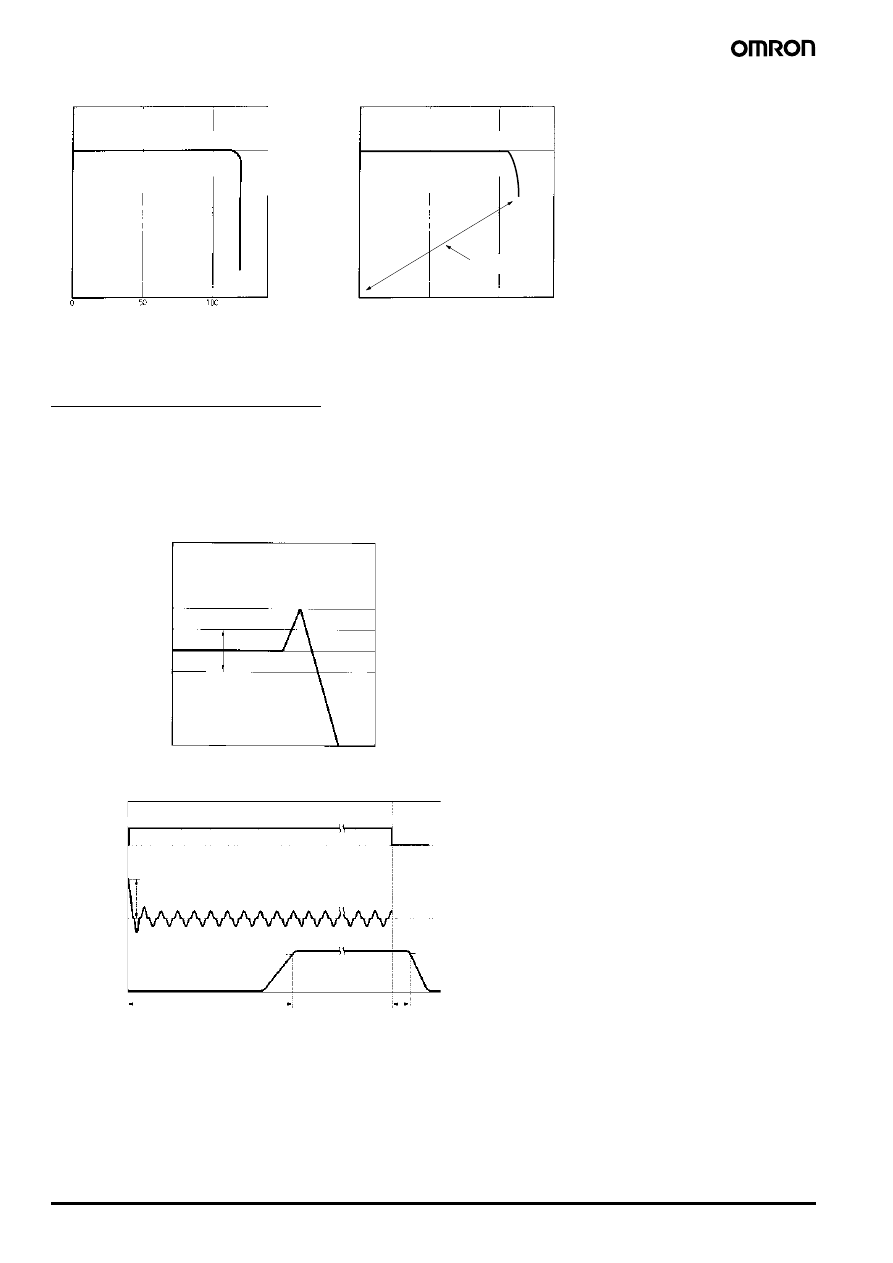
■ Overload Protection
The Power Supply is provided with an overload protection function that protects the load and the power supply from possible damage by overcur-
rent. When the output current rises above a set value (refer to the table below), the protection function is triggered, decreasing the output voltage.
When the output current falls within the rated range, the overload protection function is automatically cleared.
Note: 1. When using the 7.5-W single-output models within the input voltage range between 90 and 110 VDC, the overload protection function
will operate at currents from 95% to 160% of the rated load current.
2. When using the 90-W model at an ambient temperature exceeding 25
°C, the overload protection function will operate at currents from
92% to 111% of the rated load current.
3. When using the 100-W model with PFC in parallel operation, the overload protection function will operate at currents from 3.78 to 4.2 A.
65
70
90
240-W Model
Parallel-Unit Operation
Note: 100-VAC input: 85 to 132 VAC
Load (%)
Ambient temperature (
°C)
Load (%)
Ambient temperature (
°C)
Single-Unit Operation
Installation A
Installation A
90-W Models
Load (%)
Ambient temperature (
°C)
Installation A
Installation B
240-W Model
Single-Unit Operation
Note: 100-VAC input: 85 to 132 VAC
S82K-P09024:
85-VAC input
S82K-P24024:
100-VAC input
(see note)
S82K-P24024:
100-VAC input
(see note)
(A) Standard (Vertical) Installation
(B) Horizontal Installation
Top
Top
S82K-
@@
Note: The derating curve above can be ensured for
the above two kinds of installations.
(Not permitted for
240-W models.)
Single output
Dual
outputs
Single output
3 W
7.5 W
7.5 W
15 W
30 W
50 W
90 W
100 W
240 W
Set value
105% to 160% of rated load
current (see note 1)
105% to
250% of rat-
ed load cur-
rent
105% to 160% of rated load current
101% to
111% of rat-
ed load cur-
rent (see
notes 2 and
3)
105% to 160% of rated load
current (see note 3)
Operation
Inverted L drop type, automatic reset
Inverted L drop/intermittent
operation type, automatic
reset
Inverted L drop type, automatic reset
L-18
Switch mode Power Supply
S82K
When Using
± Output Models
The +V output detects the total output power (+V output and -V output) to trigger the short-circuit protection against overcurrent. This protection
varies depending on the -V output state. The -V output independently triggers the short-circuit protection.
■ Overvoltage Protection (S82K-24024T Models Only)
The Power Supply is provided with an overvoltage protection function that protects the load and the Power Supply from possible damage by over-
voltage. When the output voltage rises above a set value, the protection function is triggered, shutting off the output voltage. If this occurs, reset
the Power Supply by turning it off for 1 minute min. and then turning it on again.
■ Inrush Current, Startup Time, Hold Time
50
0
100
Output v
oltage (V)
Output current (%)
Intermittent
operation
Output v
oltage (V)
Output current (%)
Rated voltage
3-/7.5-/15-/90-/100-/240-W Models
30-/50-W Models
Rated voltage
Note: Do not short-circuit the output terminals of the S82K or use the S82K with excessive output current for a long time, otherwise the
internal circuitry of the S82K may be deteriorated or damaged.
10%
−10%
Output v
oltage (V)
Variable range
Rated output
voltage
Overvoltage
protection
operating
90%
96.5%
Input ON
AC input voltage
AC input current
Output voltage
Inrush current on input application
Input OFF
Startup time: 100 to 1000 ms
max. depending on the model.
Hold time
(20 ms min.)
Switch mode Power Supply
S82K
L-19
Power
Supplies
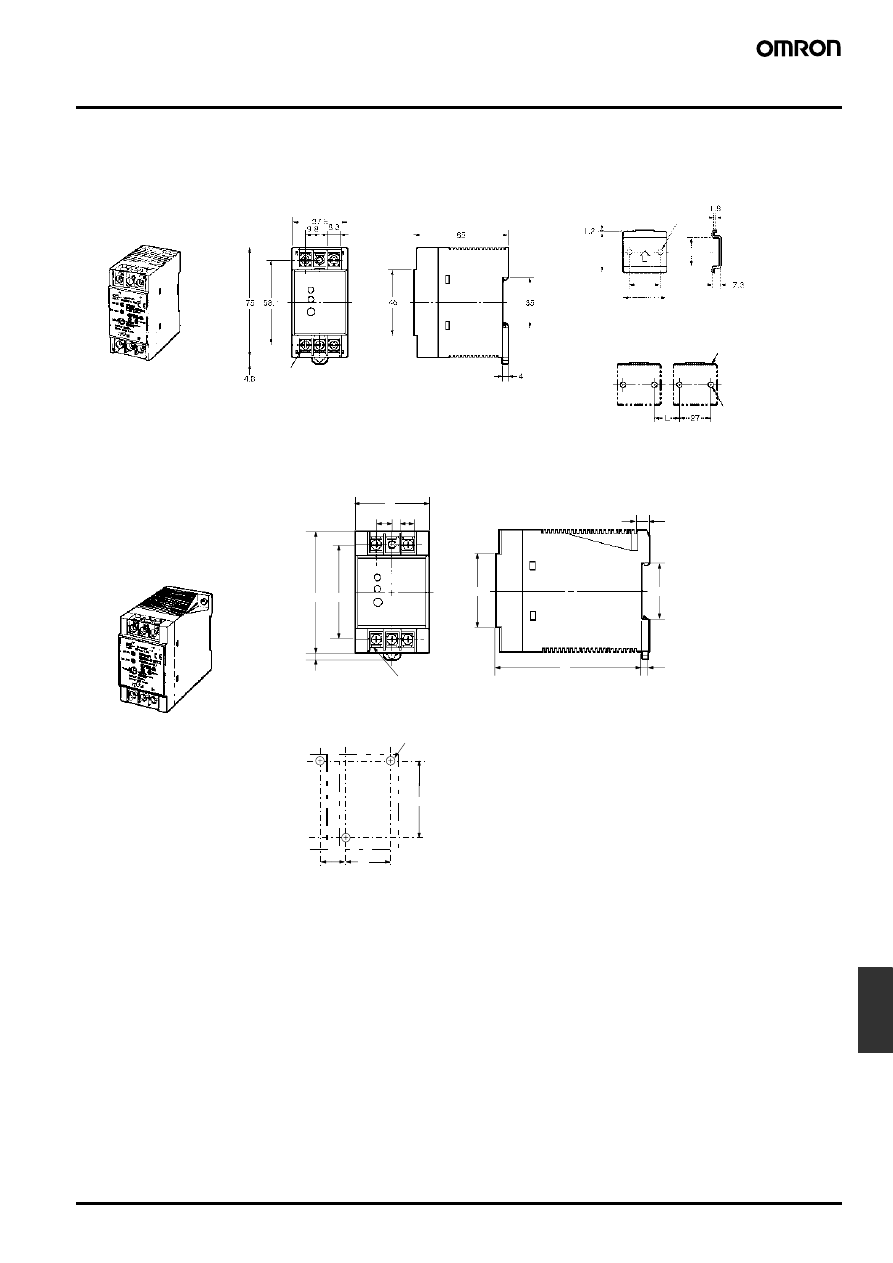
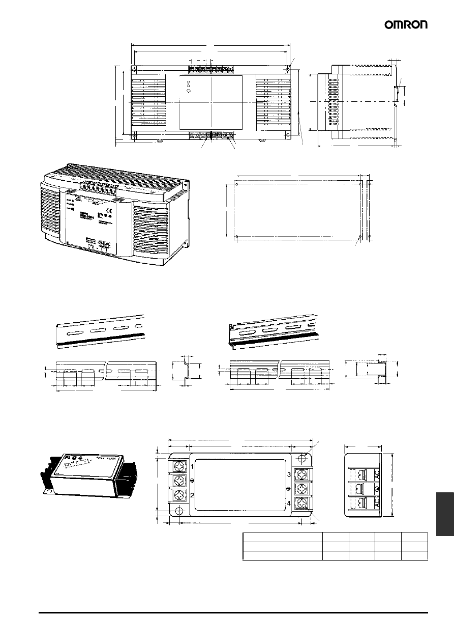
Dimensions
Note: All units are in millimeters unless otherwise indicated.
35
±0.15
25
±0.15
37.5
±0.1
27
±0.1
M3.5 with square washer
Mounting Holes
Two, 4.5
±0.1 dia.
S82K-003
@@ (3 W)
S82K-007
@@ (7.5 W)
(sliding
7 max.)
Note: If more than one Power Supply is installed in a
row, keep a distance of 20 mm min. (L = 20 mm
min.) between each adjacent Power Supply.
Mounting Brackets
(Supplied with the Switching Power Supply)
Used when not mounting the Power Supply directly
on the DIN track.
Attached
Mounting
Bracket
M4 or 4.5-dia.
hole
75
58.1
45
9.8
8.3
45
91
5
35
7.5
60
L
35
S82K-015
@@ (15 W)
Mounting Holes
Two, M4 or 4.5-dia. mounting holes
4.6
(sliding 7 max.)
M3.5 with square
washer
Note: If more than one Power Supply is installed in a row, keep
a distance of 20 mm min. (L = 20 mm min.) between each
adjacent Power Supply.
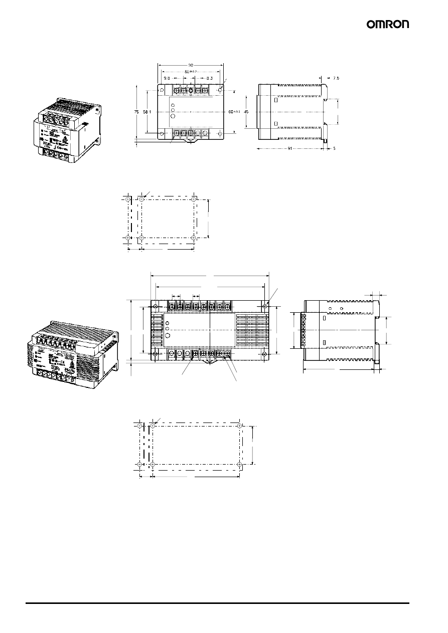
L-20
Switch mode Power Supply
S82K
4
60
80
L
35
(sliding 7 max.)
M3.5 with square washer
Four, M4 or 4.5-dia. mounting holes
Four, 4.5 dia.
Mounting Holes
S82K-030
@@ (30 W)
S82K-05024 (50 W)
Note: If more than one Power Supply is
installed in a row, keep a distance of
20 mm min. (L = 20 mm min.) between
each adjacent Power Supply.
60
135
L
58.1
75
4
60
±0.2
145
135
±0.2
91
35
7.5
5
45
8.3
9.8
Four, M4 or 4.5-dia. mounting holes
(sliding 7 max.)
M3.5 with square washer
Short bar
M3.5 terminal screw
Four, 4.5 dia.
Mounting Holes
S82K-
@09024 (90 W)
S82K-
@10024 (100 W)
Note: If more than one Power Supply is
installed in a row, keep a distance of
20 mm min. (L = 20 mm min.) between
each adjacent Power Supply.
Switch mode Power Supply
S82K
L-21
Power
Supplies
■ Accessories
M3.5 terminal screw
130
112.8
100
115
±0.2
4
9.8
8.3
35
7.8
27.5
270
115
±0.2
4.2
138
280
270
±0.2
L
S82K-
@24024@
M3.5 with square washer
Short bar
M3.5 terminal screw
Mounting Holes
Four, M4 or 4.5-dia. mounting holes
Four, 4.5 dia.
(sliding 8 max.)
Note: If more than one Power Supply is installed in a row, keep a distance of
20 mm min. (L = 20 mm min.) between each adjacent Power Supply.
4.5
15
25
25
25
25
10
10
1,000 (500)
7.3
±0.15
35
±0.3
27
±0.15
1
15 (5)
4.5
15
25
25
25
25
15
10
10
1,000
35
±0.3 27
24
16
29.2
1
1.5
39
±0.5
B
±1
D
±1
6.5
4
6.5
C
±0.5
4
47
±1
(see note)
(see note)
PFP-100N2
16 max.
A max.
Six, M4
16 max.
Nameplate
Two, 4.8 dia.
(Mounting
holes)
Mounting Track (Order Separately)
PFP-100N/PFP-50N
Note: The values shown in parentheses are for the
PFP-50N.
Noise Filter (Order Separately)
S82Y-JF3-N for 3- to 50-W Models
S82Y-JF6-N for 90- and 100-W Models
Model
A
B
C
D
S82Y-JF3-N
107
75
90
26
S82Y-JF6-N
117
85
100
30
L-22
Switch mode Power Supply
S82K
Precautions
!Caution
Be sure to connect the grounding line. Not doing so may result in
electric shock.
!WARNING
Do not attempt to disassemble the Power Supply or touch its inter-
nal parts while power is being supplied. Doing so may result in
electric shock.
Do not touch the terminals of the Power Supply within one minute
after power has been turned OFF. Doing so may result in electric
shock due to a residual voltage.
Do not touch the Power Supply Unit while power is being supplied
or immediately after power has been turned OFF. Doing so may
result in a skin burn due to high temperature of the Power Supply.
Mounting
To improve and maintain the reliability of the Power Supply over a
long period of time, adequate consideration must be given to heat
radiation.
The Power Supply is designed to radiate heat by means of natural
air-flow. Therefore, mount the Power Supply so that air flow takes
place around the Power Supply.
When mounting two or more Power Supplies side-by-side, allow at
least 10 mm spacing between them, as shown in the following illus-
tration.
Forced air-cooling is recommended.
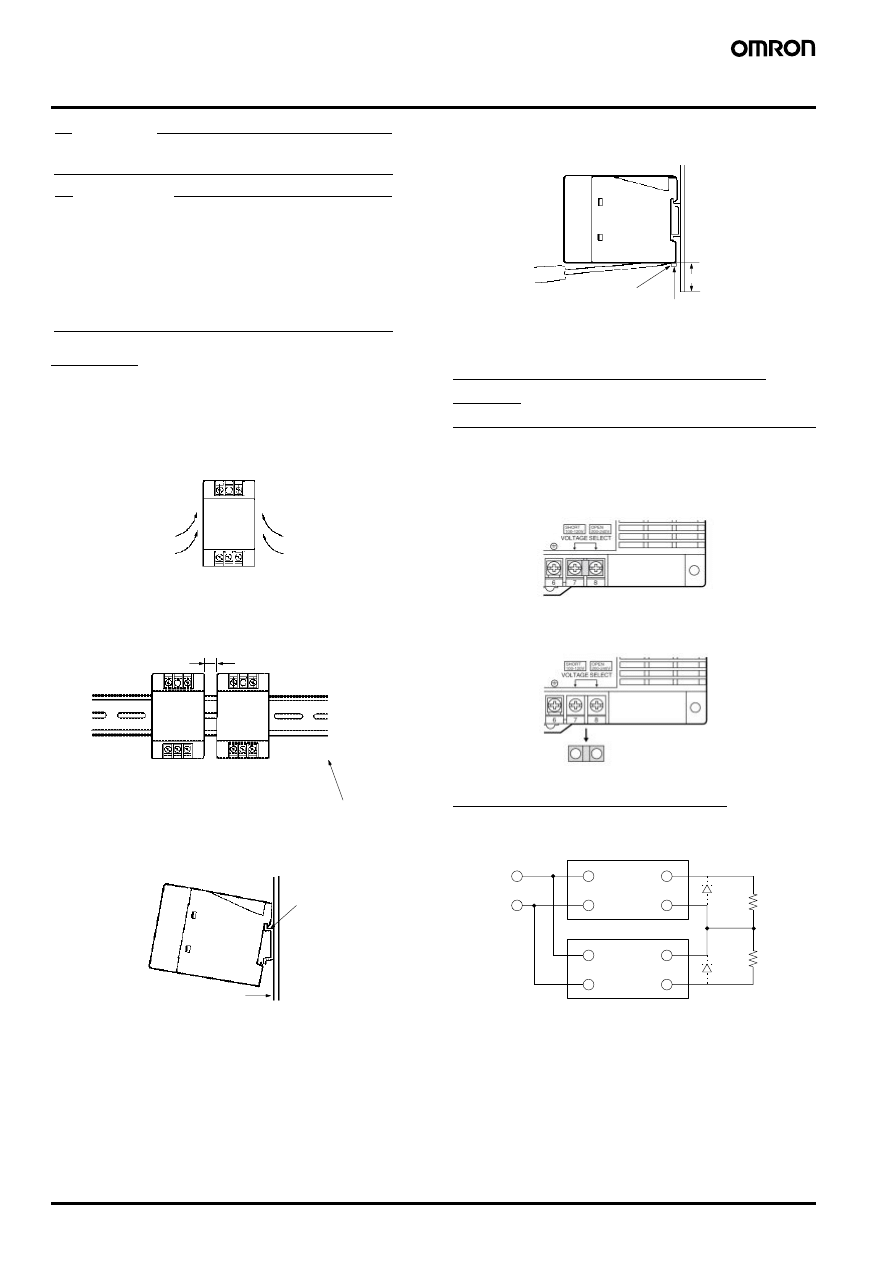
To mount the Power Supply on a DIN track, hook portion (A) of the
Power Supply to the track and press the Power Supply toward direc-
tion (B).
To dismount the Power Supply, pull down portion (C) with a flat-blade
screwdriver and pull out the Power Supply.
When tightening the terminals, do not tighten the terminal block to a
torque greater than 75 N.
Selection of 100 or 200 VAC Input
Voltage
(S82K-
@09024/-@10024/-24024/-24024T)
Select a 100 V or 200 V input by shorting or opening the Input Volt-
age Selector Terminals, as shown in the following diagram.
The default setting is 200 V.
Generating Output Voltage (
±)
An output of
± can be generated by using two Power Supplies as
shown below, because the Power Supply produces a floating output.
When connecting the Power Supplies in series with an operation
amplifier, connect diodes to the output terminals as shown by the
dotted lines in the figure. No diodes are required with S82K 90-W/
100-W/240-W models.
Air
10 mm min.
Short bar
(A)
(B)
C
30 mm min.
Track stopper
100 V Input
200 V Input
Remove the short bar.
Use the short bar to short-circuit
terminals 7 and 8.
+V
−V
+V
−V
INPUT
INPUT
Switch mode Power Supply
S82K
L-23
Power
Supplies
Wiring
Carefully wire the input/output terminals while paying attention to
their polarities so as to prevent incorrect wiring.
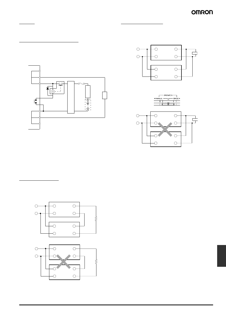
Battery Charging/Backup
With S82K-
@09024/-@10024/-24024T models, a reduction in lifetime
due to over discharge of the battery can be prevented using the DC
LOW output. (Discharge can be interrupted at 0.75 to 0.9
× 24 V.)
Note: 1. For details of charging voltages and charging currents, refer
to the specifications for the battery.
2. In order to prevent overvoltage to the battery, install an ov-
ervoltage protection circuit (90/100-W models).
3. To protect the battery in the event of incorrect operation,
such as load short-circuiting, be sure to install a fuse or cir-
cuit breaker.
4. To limit the level of charging current to the battery, install an
overcurrent limit circuit.
With other models, when connecting a battery to the load, install an
overcurrent limit circuit and overvoltage protection circuit.
Series Operation
S82K 90-W/100-W/240-W model can be operated in series.
It must be noted that the + output of the 7.5-W dual output model
cannot be connected in series to its – output.
Parallel Operation
S82K 100-W/240-W models can be operated in parallel.
Perform parallel operation with power supplies satisfying the same
specifications.
Note: When operating the S82K-P10024 or S82K-
@24024@ in paral-
lel operation, set the switch to “PARALLEL.” Refer to the derat-
ing curve for the rated current under this operation.
Parallel Operation Precautions
• The length and thickness of each wire connected to the load must
be the same so that there is no difference in voltage drop value
between the load and the output terminals of each Power Supply.
• Adjust the output voltage of each Power Supply so that there will be
no difference in output voltage between each Power Supply.
• If the S82K-P10024 or S82K-
@24024@ models are used in single
operation under the parallel operation setting, the overcurrent pro-
tection will be actuated at an output of 90% to 95% (in current), and
will not allow a 100% output.
• If the S82K-P10024 or S82K-
@24024@ models are used in parallel
operation under the single operation setting, one of them will oper-
ate at 110% output, causing severe heat derating and shortening
the service life.
14
15
16
+V
−V
9
10
11
12
13
Example: Lead Storage Battery Backup Circuit
Fuse/Circuit breaker
DC Low
Ov
er
v
o
ltage
protection circuit
Ov
ercurrent
limit circuit
Load
+V
−V
+V
−V
+V
−V
+V
−V
90-, 100-, and 240-W Models
3-, 7.5-, 15-, 30-, 50-W Models
INPUT
INPUT
INPUT
INPUT
+V
−V
+V
−V
INPUT
INPUT
Load
100- and 240-W Models
+V
−V
+V
−V
INPUT
INPUT
Load
3-, 7.5-, 15-, 30-, 50- and 90-W Models

L-24
Switch mode Power Supply
S82K
Minimum Output Current
The minimum output current of the S82K-00727 and S82K-00728 is
restricted by the output voltage and control method.
Note: All the outputs of the S82K-00727 and S82K-00728 are con-
trolled by the +V output. If the +V output current falls to 10% or
less of the rated output, the –V output voltage may drop.
Operating and Storage Environments
Do not use or store the Unit in the following places, otherwise the
Unit may malfunction or the characteristics of the Unit may deterio-
rate.
• Locations subject to direct sunlight.
• Locations subject to ambient operating temperatures outside the
range indicated by the derating curve.
• Locations subject to ambient operating humidity outside the range
of 25% to 85%.
• Locations subject to condensation as the result of severe changes
in temperature.
• Locations subject to ambient storage temperatures outside the
range of –25
°C to 65°C.
• Locations subject to corrosive or flammable gases.
• Locations subject to dust (especially iron dust) or salts.
• Locations subject to shock or vibration.
• Locations subject to exposure to water, oil, or chemicals.
In the interest of product improvement, specifications are subject to change without notice.
ALL DIMENSIONS SHOWN ARE IN MILLIMETERS.
To convert millimeters into inches, multiply by 0.03937. To convert grams into ounces, multiply by 0.03527.
Cat. No. M048-E1-06
Wyszukiwarka
Podobne podstrony:
zasilacze impulsowe 2
ZASIMP~1, Zasilacz impulsowy:
~$DANIE ZASILACZY IMPULSOWYCH
EN w8 zasilacze impulsowe
zasilacze impulsowe
11 stabilizowane zasilacze impulso
C ZASILACZE IMPULSOWE
zasilacze impulsowe
zasilacze impulsowe
Zasilacze impulsowe Przyklad BUUE ISP, Nauka i Technika, Elektrotechnika
BADANIE ZASILACZY IMPULSOWYCH (Automatycznie zapisany)
Zasilacz impulsowy SP-320, Instrukcja obsługi (2007)
Zasilacz impulsowy AD55, Instrukcja obsługi
Zasilacz impulsowy
10 Katalog OEM Zasilacze impulsowe
BADANIE ZASILACZY IMPULSOWYCH
C ZASILACZE IMPULSOWE 1
Emisja zaburzen przewodzonych zasilaczy impulsowych K Trzcinka
więcej podobnych podstron