
C
H
A
P
T
E
R
12
P
LANNING THE
I
NSTALLATION
T H O M A S A. D O O L E Y A N D
J E R A L D R. R O U N D S
THE PROCESS OF PLANNING
Planning is one of the most important parts of any project and is particularly crit-
ical in construction. One of the characteristics of construction is that it is not
repetitive. Although specific activities such as pulling cable or making termina-
tions appear to be repetitive, each is done under different circumstances. The
cumulative result of these small differences is that jobs differ considerably. As a
result, each job must be planned in detail to take its unique characteristics into
consideration.
In manufacturing, prototypes are designed and manufactured to test the
design and the manufacturing procedures. When mistakes and oversights occur,
another prototype is developed to solve the problems. This process is repeated
many times over until both the product and the process of making that product
are flawless, at which time the product goes into production.
In the construction industry, you do not have that luxury. Designers must
design correctly the first time. Constructors must build right the first time. Errors,
either in design or construction, are costly to repair or replace and cause time
delays. Some errors are hidden and do not become obvious until the system is
operating. Then, the mistakes become not only costly and time-consuming, but
129

are disastrous to those who depend on a fully operational and properly working
system.
The only way to produce a quality job is to avoid errors, omissions, and mis-
takes by properly planning and by establishing correct installation procedures. A
side benefit of the planning process, of course, is that it improves the efficiency of
installation, which results in higher profits for a contractor. Preplanning of every
aspect of fiber optic installation is not an option; it is a necessity.
MEASURING FOR CONDUIT PULLS
Planning for proper cable lengths is extremely important in fiber optic installa-
tion for two reasons. The most important is that splices cause loss in both signal
quality and strength—this should be avoided. In fact, most designers specify
point-to-point or device-to-device runs to avoid needless signal loss due to
splices. The second reason, especially important to the contractor, is that splices
cost time and money.
Measurements must be taken by an experienced field hand who understands
the importance of correct and accurate measurements. Often, this is done by the
project engineer or the job site superintendent.
There are three ways to measure the path to be used for the fiber. They are
listed from least to most desirable.
1. Measurements taken from the set of prints. This works if you want to
invest in a great deal of extra material. The objective of design drawings
is to show generally where runs are supposed to be located. However, it
is virtually impossible for the designer to anticipate all field conditions,
and it is not the designer’s intent to do so. Thus, taking accurate mea-
surements from the design drawings is not possible and results in runs
that are, at best, marginally long or short. Long pieces of fiber must be
recut and short pieces are wasted.
2. Field measurements taken with a wheel. A site visit with a measuring
wheel and a set of drawings will yield much better accuracy. Certain
characteristics of the job site are given perspective with a field visit that
are not obvious from inspection of the drawings alone. During the site
visit, the drawings can be verified for accuracy, installation details such
as pulling locations can be noted, changes such as variations in align-
ment or elevation can be identified, obstacles that might hinder the pull
can be discovered, and termination locations can be recorded.
3. Measuring with measurement/pull tape. By far the most accurate and
efficient method of measurement is with measurement/pull tape (some-
times called mule tape). This is a flat ribbon, consecutively numbered in
feet, that is usually made with polyester or aramid yarn and sometimes
130
CHAPTER 12 — PLANNING THE INSTALLATION

coated with plastic for waterproofing. It comes in different lengths and
pull strengths.
Completing the measurement process requires adding extra length for
splices, terminations, and future access coils, if specified. The amount of addi-
tional cable needed for splicing depends on site conditions, splicing method used,
and long range plans for cable usage. Termination needs only about 7 to 10 feet
of additional cable beyond the place the terminal will be mounted. Access or
repair coils generally range in length from 30 to 50 feet per span. A good guide-
line is to allow 1 percent extra for outside plant cable and 5 to 7 percent extra for
inside cable.
SPLICING
Fusion splicing cannot be done in explosive environments such as manholes.
Therefore, each end coming into the splice that will finally end up in the manhole
will have to have enough length to reach a tent or van near the manhole where
the splice will actually be made. Usually, about 30 feet of extra length should be
added for each side of the splice—resulting in additional 60 feet of cable.
Mechanical splicing can be done inside manholes. Mechanical splices require
only about 10 feet of overlap, instead of the 60 feet for a fusion splice. Remember
that these measurements are in addition to whatever length will be required to
properly rack the cable within the manhole.
TERMINATIONS
When terminating fiber, it is important to place the terminal in a safe, noncon-
gested area. If the end user has no preferences, place the terminal as close as pos-
sible to the fiber optic transmission equipment. It is most important to protect the
exposed fibers, so choice of a termination location must consider a working envi-
ronment that allows adequate working space.
EFFICIENT PULLING
When installers first become involved in fiber optic installations, they can easily
become overconfident about how much cable length can be successfully pulled at
one time. This is probably because of the small size and weight of fiber optic
cable. It is better to divide a pull in half, or even thirds, usually at corners or pull
boxes, than to fail in pulling a long run.
A pulling operation must be discontinued when the pulling tension reaches
the cable limit. The discontinued pull will have to be aborted, the cable pulled
back out and replaced on the reel, and the pull started again, either with shorter
CHAPTER 12 — PLANNING THE INSTALLATION
131

runs or better lubrication or both. The cable may be reused if the pull or extrac-
tion has not damaged it.
Every effort must be made to plan the pull so that pulling locations have
plenty of work space. The knowledgeable designer will designate several appro-
priate locations for breaking up the pull. The installer must ensure that if the
designer has not indicated where multiple pulls are necessary, he or she can deter-
mine appropriate locations for intermediate pulls before work is begun in the
field. It is better to tie up one lead technician before the pulling starts than the
whole crew after it has begun.
Most point-to-point pulls can be accomplished by crews of two or three peo-
ple. One person pays the cable off the reel and into the duct in order to reduce tail
load (the term used to designate that force required to get cable off the reel and
into the duct). One or two people pull at the other end. The size of crew is deter-
mined by considerations such as:
Length of pull
Total degrees of bend
Tail loading
Use of lubricant
Use of power pulling equipment
When planning to start a pull, the installer must make sure there is enough
time to finish the job the same day. It is unwise to leave half a reel of cable, worth
anywhere from $5,000 to $375,000, lying around in unsecured areas. If a reel
must be left exposed to the public, strong consideration should be given to assign-
ing a security guard to watch over the reel. An occasional investment of $75 or
$100 to avoid theft of an expensive reel of cable, to say nothing of the distur-
bance to the job if the cable is gone when installers arrive to begin work in the
morning, is a wise investment
Exact terminating locations must be identified in advance. This obvious
though often overlooked step can lead to costly mistakes if forgotten. The cable
must be pulled all the way to where it will be terminated, not just into the room.
The designer should provide a fold-flat diagram (which results from folding out
the walls of the room as if they were the sides of a box hinged at the intersections
of the walls and the floor) for each terminating room as a part of the initial plan-
ning walkout.
ADEQUATE DUCT SPACE
Current industry practice, outside telephony, tends not to utilize available duct
space very efficiently. As a result, one often finds a 1/2-inch fiber cable as the only
cable in a 4-inch duct. As a matter of good design, cable should fill approxi-
mately 60 to 70 percent of the available duct space.
132
CHAPTER 12 — PLANNING THE INSTALLATION

Since it is difficult to pull cable into a duct that is already occupied, it is very
important to detail, on the print, where the different media will be pulled. Since
most fiber cables are 3/4-inch or smaller in diameter, for efficient use, the larger
3- or 4-inch diameter conduits should be subdivided with innerducts.
Innerduct is flexible, nonmetallic conduit that is pulled in multiples into the
main conduit. It is made of polyethylene and comes with a pull rope already
installed within it. Innerduct serves a threefold purpose:
Subdividing the main duct
Protecting the fiber cable
Reducing friction
The inside of the innerduct is designed to let the cable glide smoothly within
it. This is accomplished by the use of special coatings and by the physical proper-
ties of the inner wall. Corrugated innerduct is the most popular form because of
its flexibility. A 3-inch conduit can be subdivided with up to four 1-inch
innerducts; up to six 1-inch innerducts can be placed in a 4-inch conduit.
Innerduct not only allows the initial fiber installation to be effectively accom-
plished, but allows expansion capabilities to be built into the system. This can
provide great return on investment if there is any expectation of future expansion
of the fiber system.
INITIAL PLANNING WALKOUT
Prior to the start of cable pulling, a planning walkout should be performed by the
project engineer, the lead technician, and the project superintendent. The project
engineer, responsible for system design, will be well aware of the customer’s
needs. The lead technician, an experienced fiber installer who will not necessarily
be the one who will do the installation, has the responsibility to plan and to
answer as many questions as possible before the crew is on site. The superinten-
dent can provide general project information and needs to know as much as pos-
sible about the installer’s activities to coordinate with other trades and activities
in the vicinity of the installation.
The walkout should start at one termination site (Figure 12-1). This location
will be designated with a clearly stated name, such as “#12 Communication
Room.” A rough fold-flat sketch will identify the fiber terminal location and
locations of other major system components, as well as other relevant features in
the room. The floor and walls will be marked with a pencil to indicate approxi-
mate locations of terminations. Notes should be made on the sketch concerning
conduit type and size, as well as whether pull string or measurement/pull tape has
been used. Verification of whether multiple ducts are involved is requested from
the superintendent.
CHAPTER 12 — PLANNING THE INSTALLATION
133
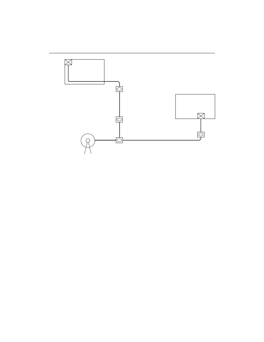
Figure 12-1
Preplanning walkout sketch.
Identification should be made defining which conduits go where either by
visual inspection or by tugging on the pull tape. The path of the conduit should
then be walked, making note on the diagram of any pull boxes, manholes, or
other abnormalities. This process must be carried out for each run on the job.
The more information the engineer provides on the print, the faster the
installation will progress. Remember, the object of this planning walkout is to
prevent the entire pulling crew from being idle while the lead technician tries to
track down the engineer or superintendent for clarifications or additional infor-
mation.
REVIEW QUESTIONS
1. The most accurate method of measuring for conduit pulls is ___________
a. from a set of prints.
b. field measurements taken with a wheel.
c. measuring with a pull tape.
134
CHAPTER 12 — PLANNING THE INSTALLATION
1
2
3
4
5
1 Room Location for Terminations
2 Bends
3 Conduit Size
4 Manholes
5 Pull Locations

2. How much extra cable must be added to make a fusion splice in a man-
hole?
a. 30 feet
b. 1 percent
c. 30 feet for each side of the splice
d. 10 feet
3. Subdividing larger conduits with innerducts _____________
a. efficiently uses duct space.
b. allows for future expansion.
c. offers additional protection to the fiber optic cable.
d. all of the above
4. The purpose of a planning walkout is to _____________
a. get a rough idea of the installation.
b. measure the conduit run.
c. clarify all the final details.
d. none of the above
CHAPTER 12 — PLANNING THE INSTALLATION
135

Wyszukiwarka
Podobne podstrony:
12 kontrola podzespołów instalacji powietrznej hamulców
2 BEFORE BEGINNING THE INSTALLATION
12 Put the verb into the correct form
Guide to the installation of PV systems 2nd Edition
12 kontrola podzespołów instalacji powietrznej hamulców
Kenyon, Sherrilyn Dark Hunter 12 Seize the Night
12 Rozwiązania materiałowe i instalacyjne systemów odprowadzania ścieków z budynków wraz z przykanal
11 12 vocab THE IMPOSIBLY CURVY BODY
12 on the Augustan Age and the Age of Sensibility
12 kontrola podzespołów instalacji powietrznej hamulców
Instructions for the installer S
39 zalacznik nr 12 specyfikacja tech instal co
Planning the Off Season 5 Key Messages
Charlie Richards Kontra s Menagerie 12 Ruffling the Peacock s Feathers
12 Can u the pride in the panther[Czy widzisz dumę w panter
Chapter 8 10 Planning the Active Directo
więcej podobnych podstron