
Method Development in High-
Performance Liquid
Chromatography

The Chromatographic Process
• Diffusion in liquids is 100 times slower than
diffusion in gases. Therefore, in liquid
chromatography it is not feasible to use
capillary columns – HPLC uses packed
columns
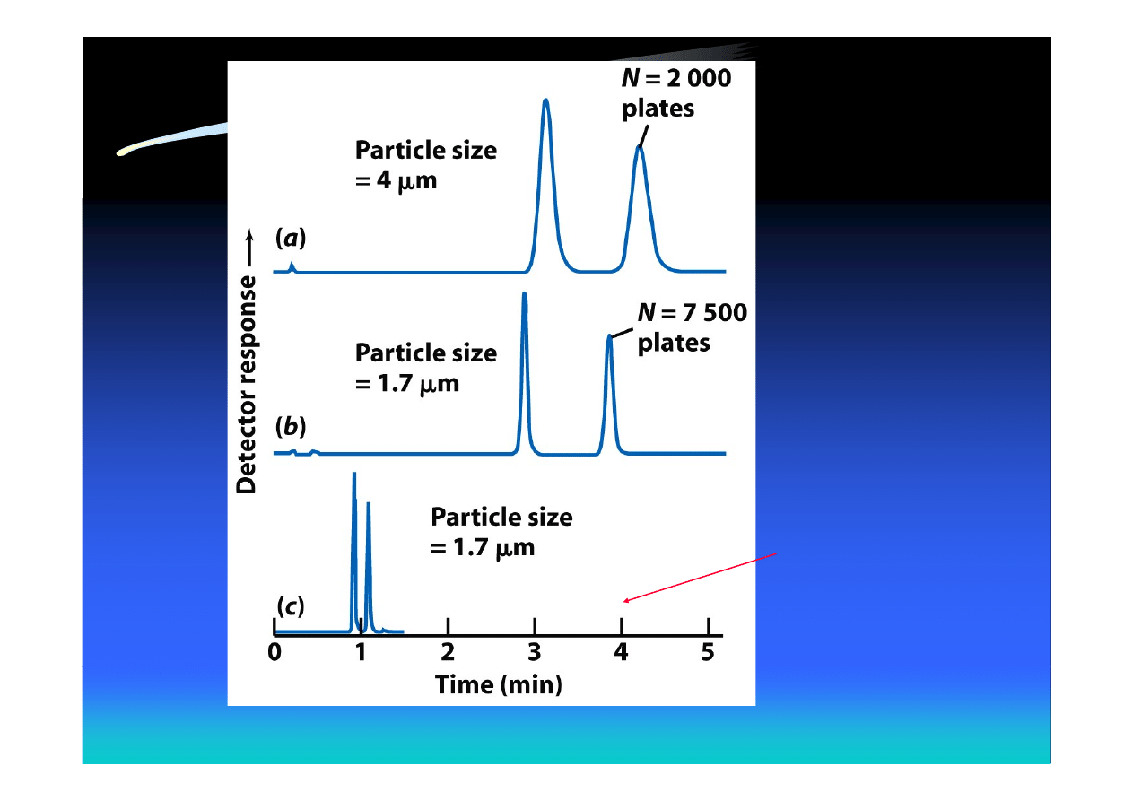
• Small particles give high efficiency but
require high pressure. Typical particle sizes
in HPLC are 3-10 μm
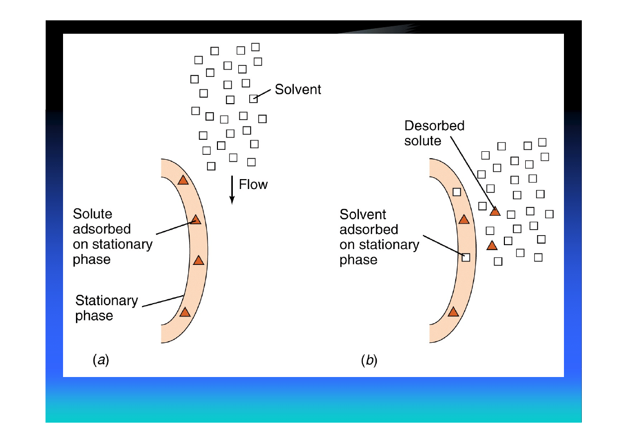
Stronger solvent than
in (b)
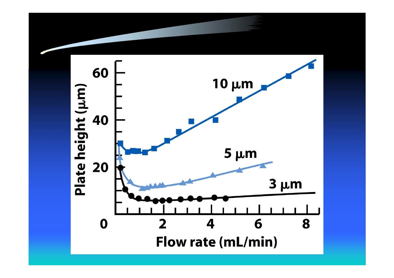
Plate Height as a Function of Flow
Rate

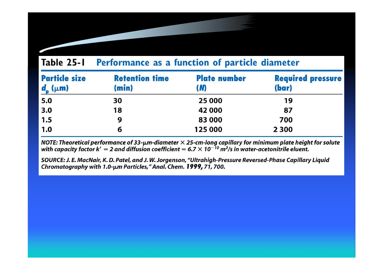
Number of Theoretical Plates in
HPLC
Under optimum conditions (near H
min
), the number of
theoretical plates in a column of length L is
• Small particles reduce eddy diffusion (A term)
• Small particles reduce the distance solute must diffuse in
the mobile phase (C term)
( )
( )
μm
cm
3500
p
d
L
N
≈

Smaller Particle Size Leads to
• Higher plate number
• Higher pressure
• Shorter run time (higher sample
throughput)
• Lower detection limit

Required Column Pressure
The pressure required to drive the solvent through
a column is
f – factor depending on particle shape and packing
η – viscosity of the solvent
r – column radius
2
p
2
d
r
L
u
f
P
x
π
η
=

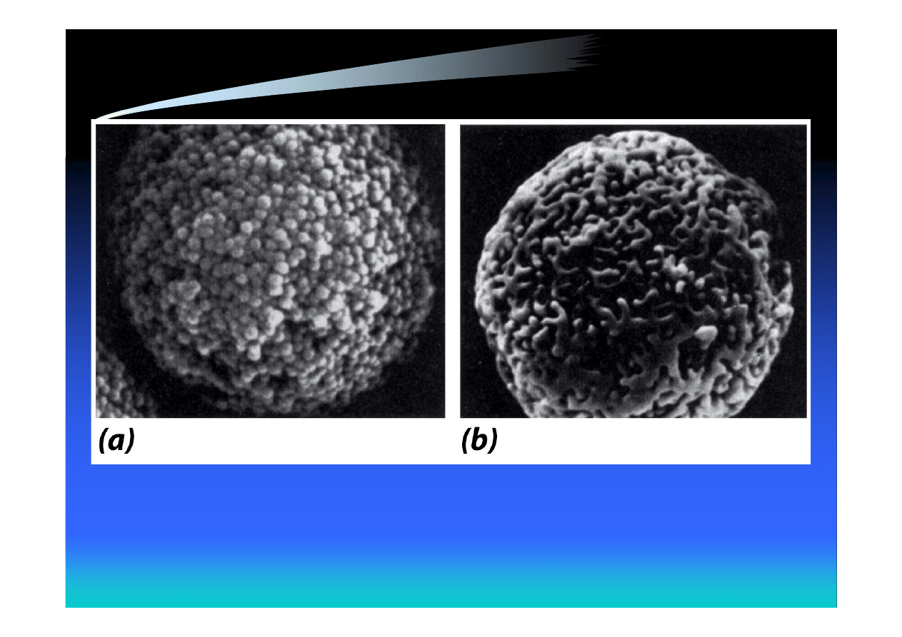
The Stationary Phase in HPLC
• The most common support – spherical
microporous silica particles permeable to
solvent. Silica dissolves above pH 8 and
should not be used above this pH (special
grades are stable up to pH 9 or 10)
• For chromatography of basic compounds at
pH 8-12, polymeric supports (polystyrene)
can be used
50% porosity; S = 150 m
2
/g
70% porosity; S = 300 m
2
/g
Microporous Silica Particles
Nominal pore size is 10 nm
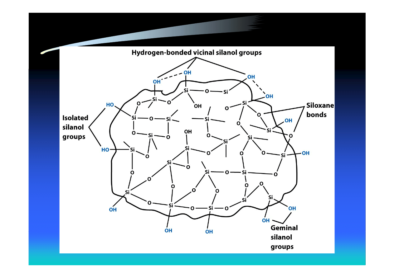
Schematic Structure of Silica Gel
Up to 8 μmol/m
2
Si-OH
Protonated at pH 2-3

Uses of Silica in HPLC
• Bare silica is used as the stationary phase in
adsorption chromatography
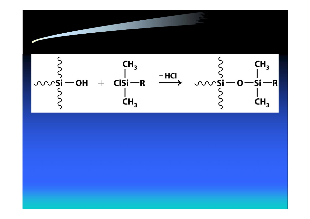
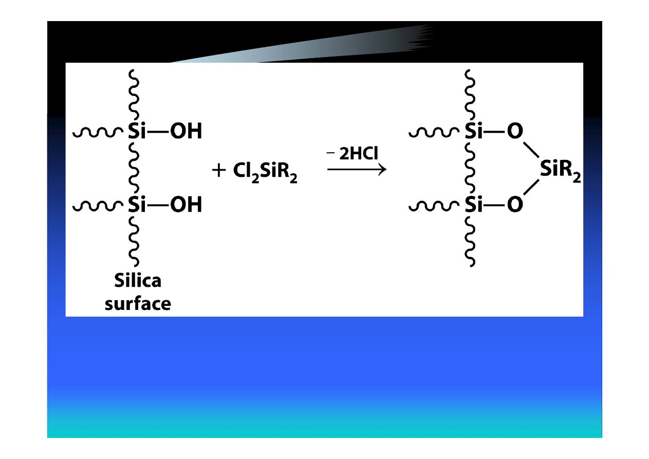
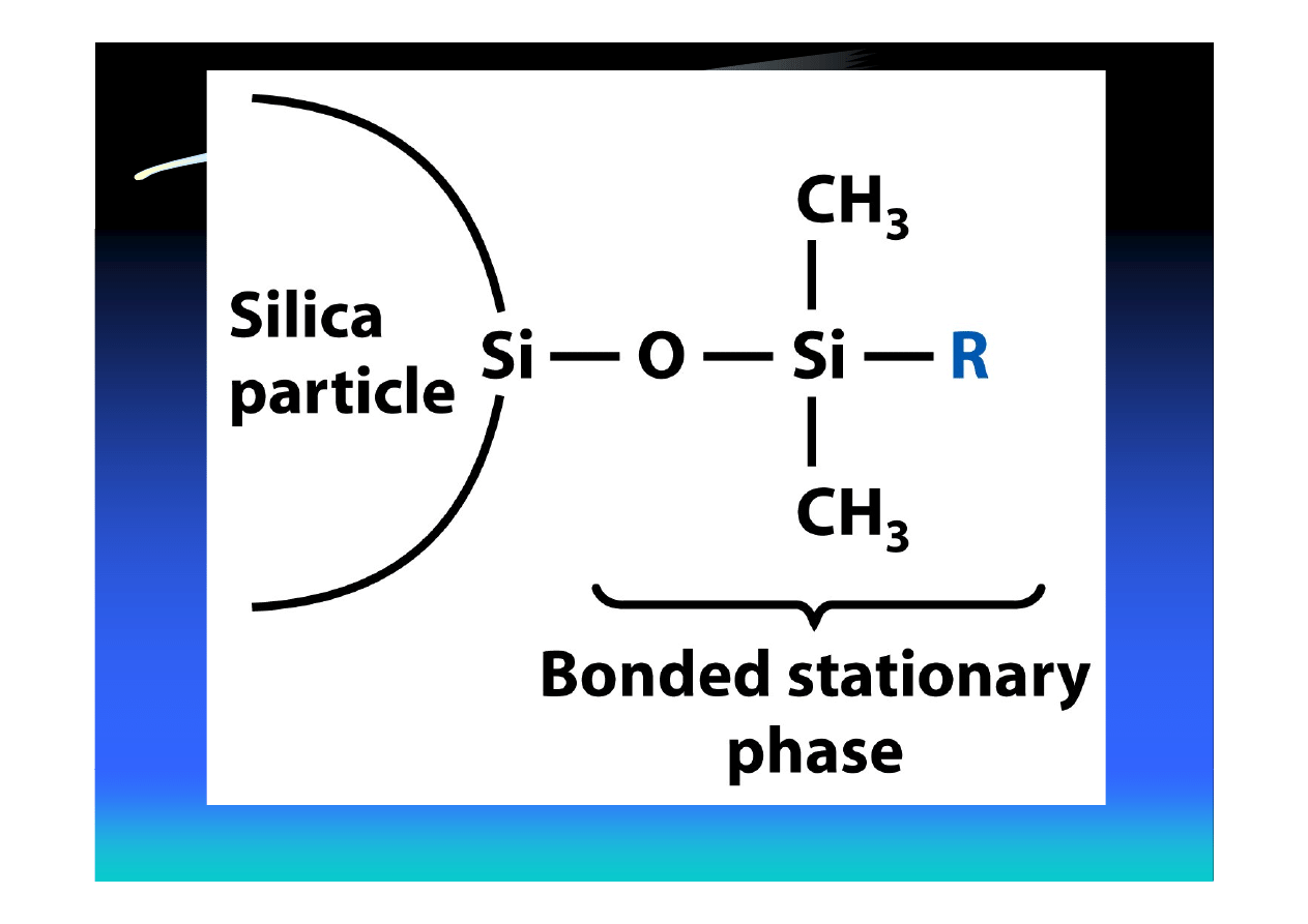
• In liquid-liquid partition chromatography,
the stationary phase is chemically bonded to
the silica surface
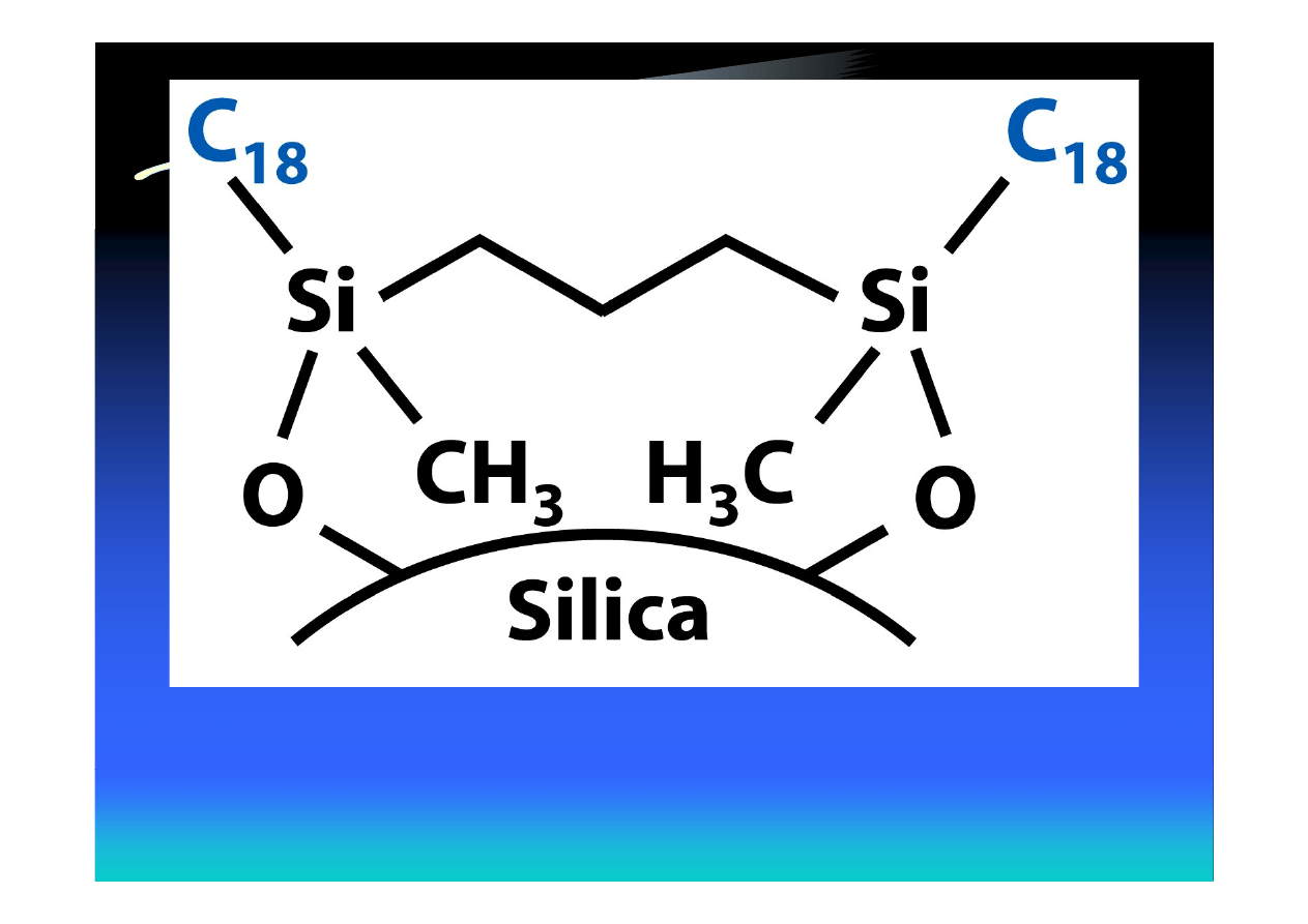
Bidentate C
18
stationary phase stable in the pH range 2-11.5
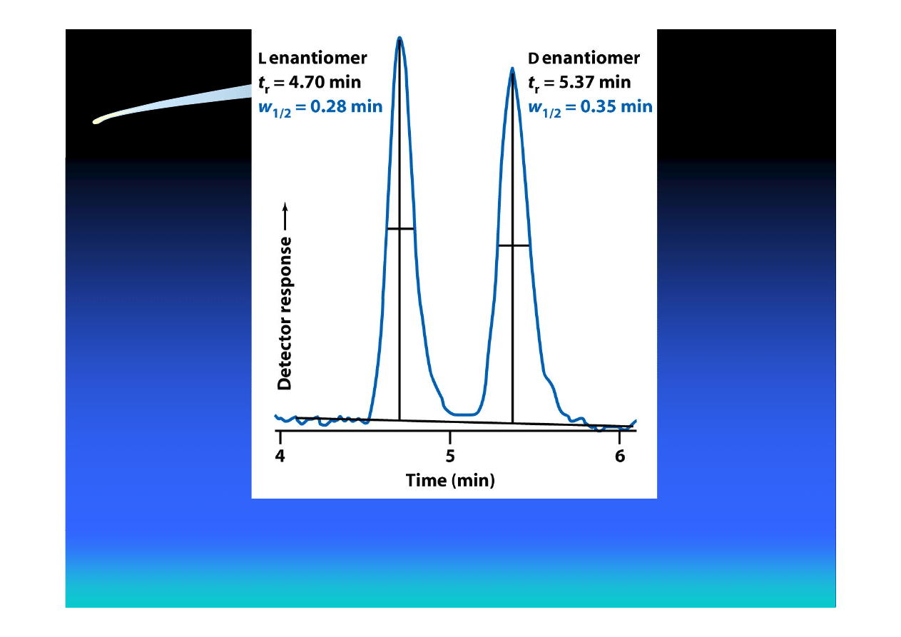
Baseline separation of enantiomers of the drug Ritalin by HPLC
with a chiral stationary phase
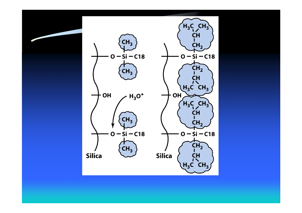
Bulky isobutyl groups protect siloxane bonds from hydrolysis at low pH

Superficially Porous (Pellicular)
Particles
• A stationary phase (e.g. C
18
) is bonded to
the thin, porous outer layer
• Mass transfer of solute is 10 times faster
than into fully porous particles of the same
diameter
• Especially suitable for separation of
macromolecules (proteins), which diffuse
more slowly than small molecules
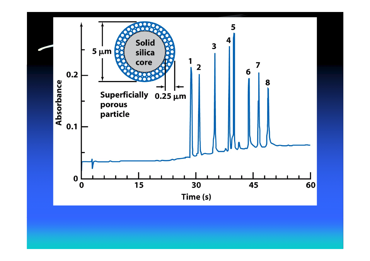
Proteins separated on C
18
-silica. 1 – angiotensin II; 2 – neurotensin;
3 – ribonuclease; 4- insulin; 5 – lysozyme; 6 – myoglobin; 7 – carbonic
anhydrase; 8 - ovalbumin

The Elution Process
• In adsorption chromatography, solvent
molecules compete with solute molecules
for sites on the stationary phase
• Elution can be described as a displacement
of solute from the stationary phase by
solvent

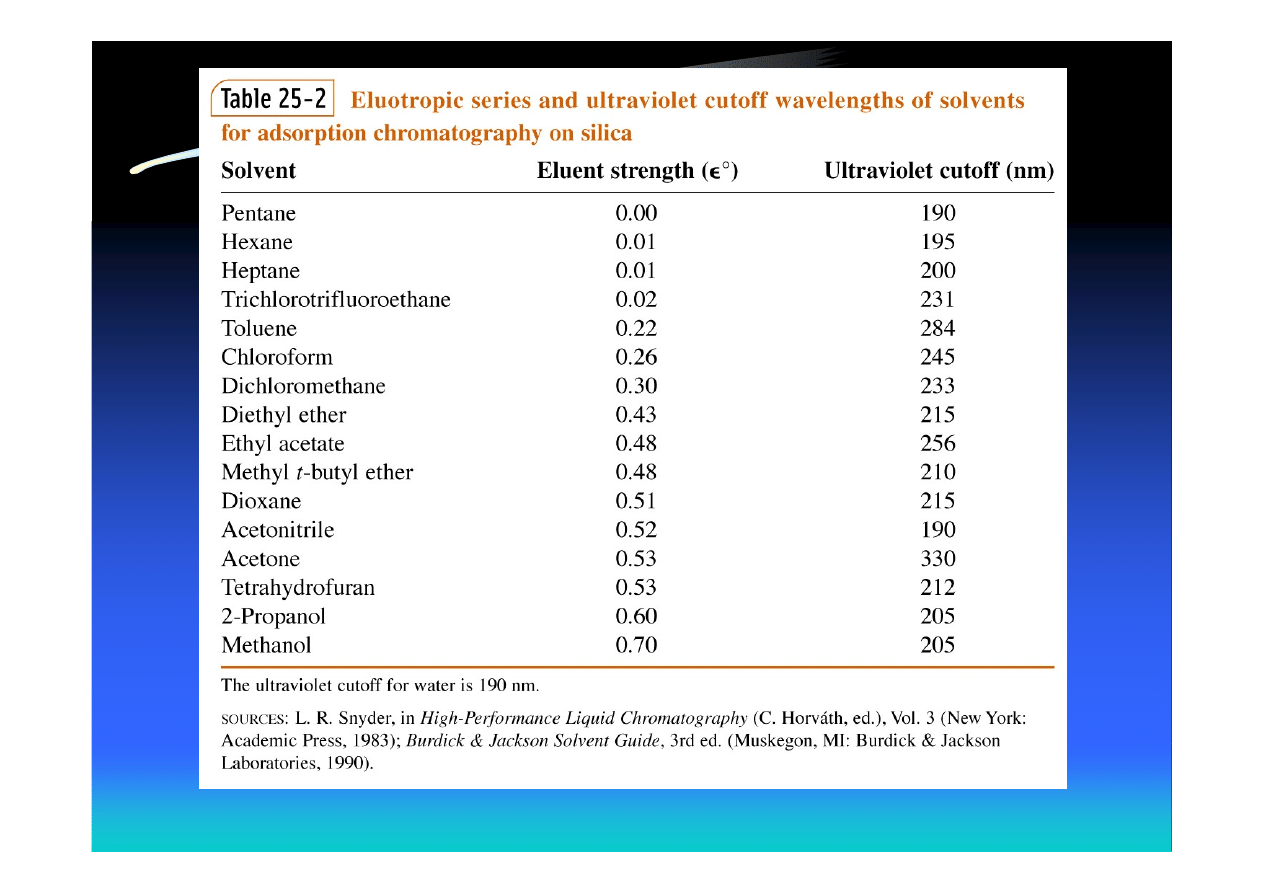
Eluotropic Series
• An eluotropic series ranks solvents by their
relative abilities to displace solute from a given
adsorbent
• The eluent strength (ε
°) is a measure of the
solvent adsorption energy, with the value for
pentane defined as 0 on bare silica
• The more polar the solvent, the greater is its eluent
strength and the more rapidly will solutes be
eluted from the column

Classification of HPLC Modes
• Normal-phase chromatography
– Polar stationary phase
– More polar solvent has higher eluent strength
• Reversed-phase chromatography
– Nonpolar stationary phase
– Less polar solvent has higher eluent strength

Elution Modes in HPLC
• Isocratic elution – performed with a single
solvent or constant solvent mixture
• Gradient elution – continuous change of
solvent composition to increase eluent
strength (analogous to temperature
programming in GC)

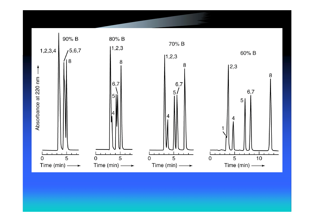
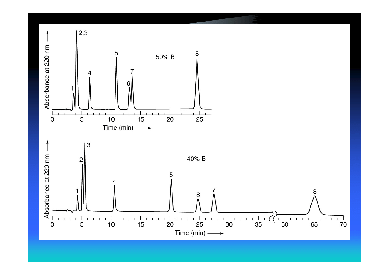
Example: Isocratic Separation of
Aromatic Compounds by RP HPLC
Solvent A – aqueous buffer
Solvent B - acetonitrile
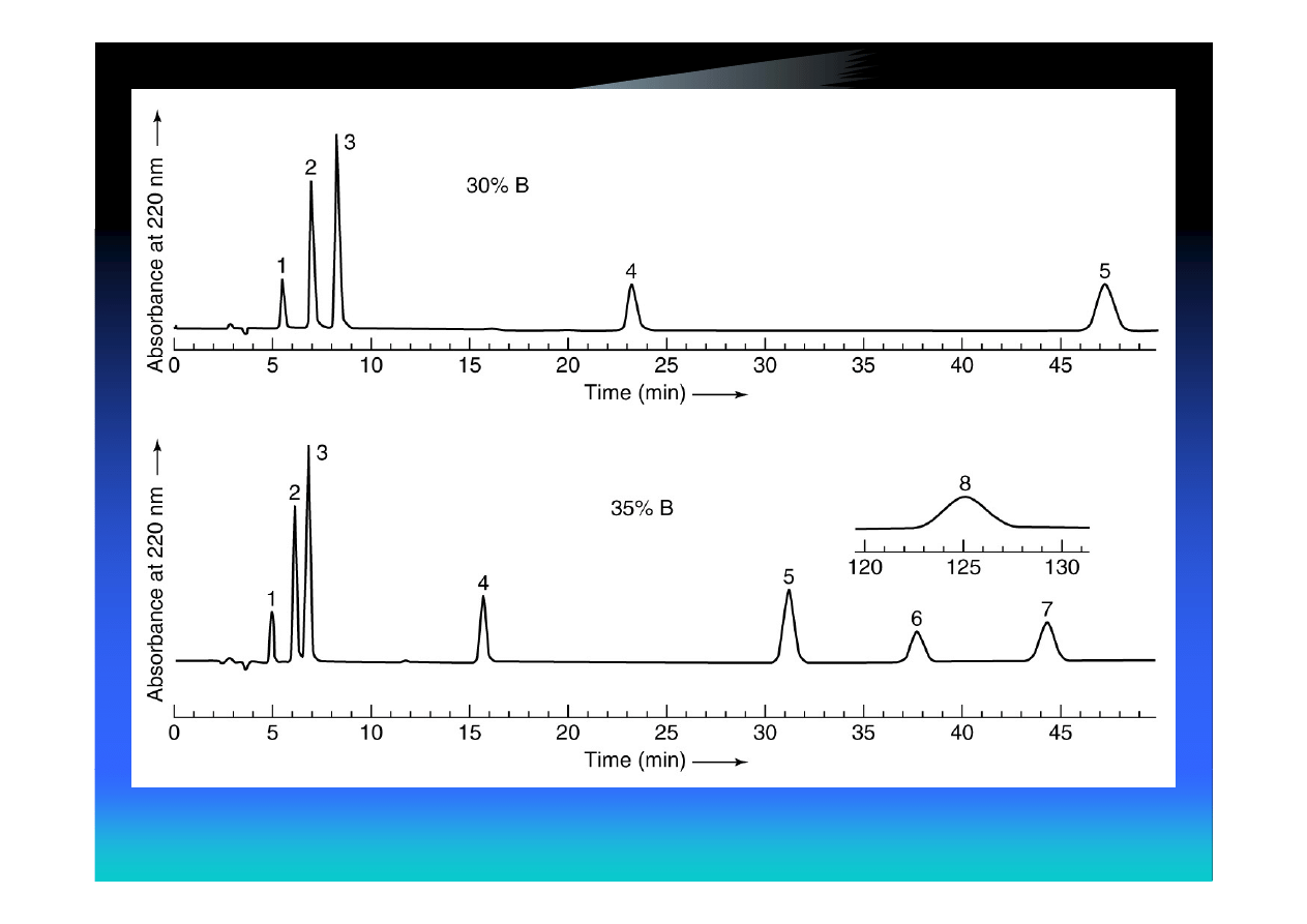

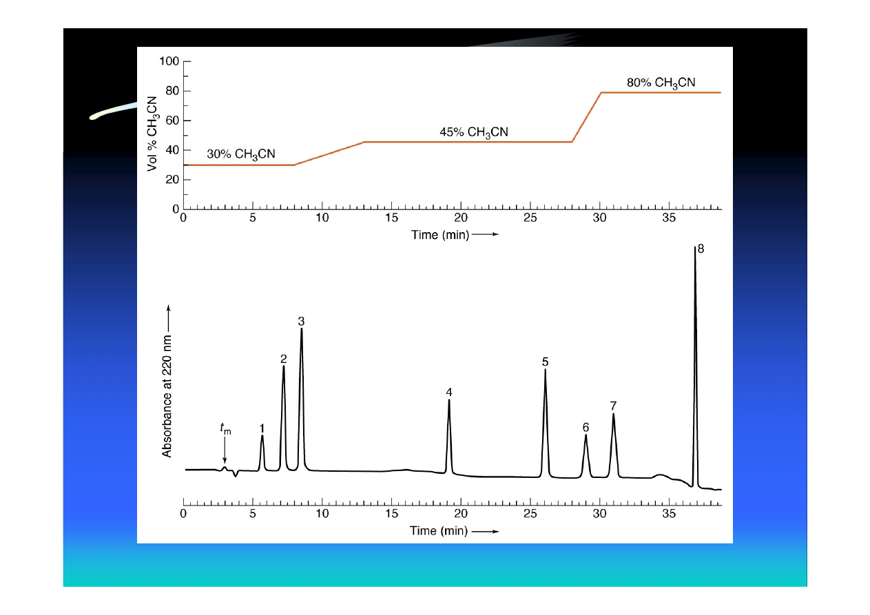
Gradient Elution of the Same
Mixture of Aromatic Compounds
• Same column, flow rate and solvents were
used

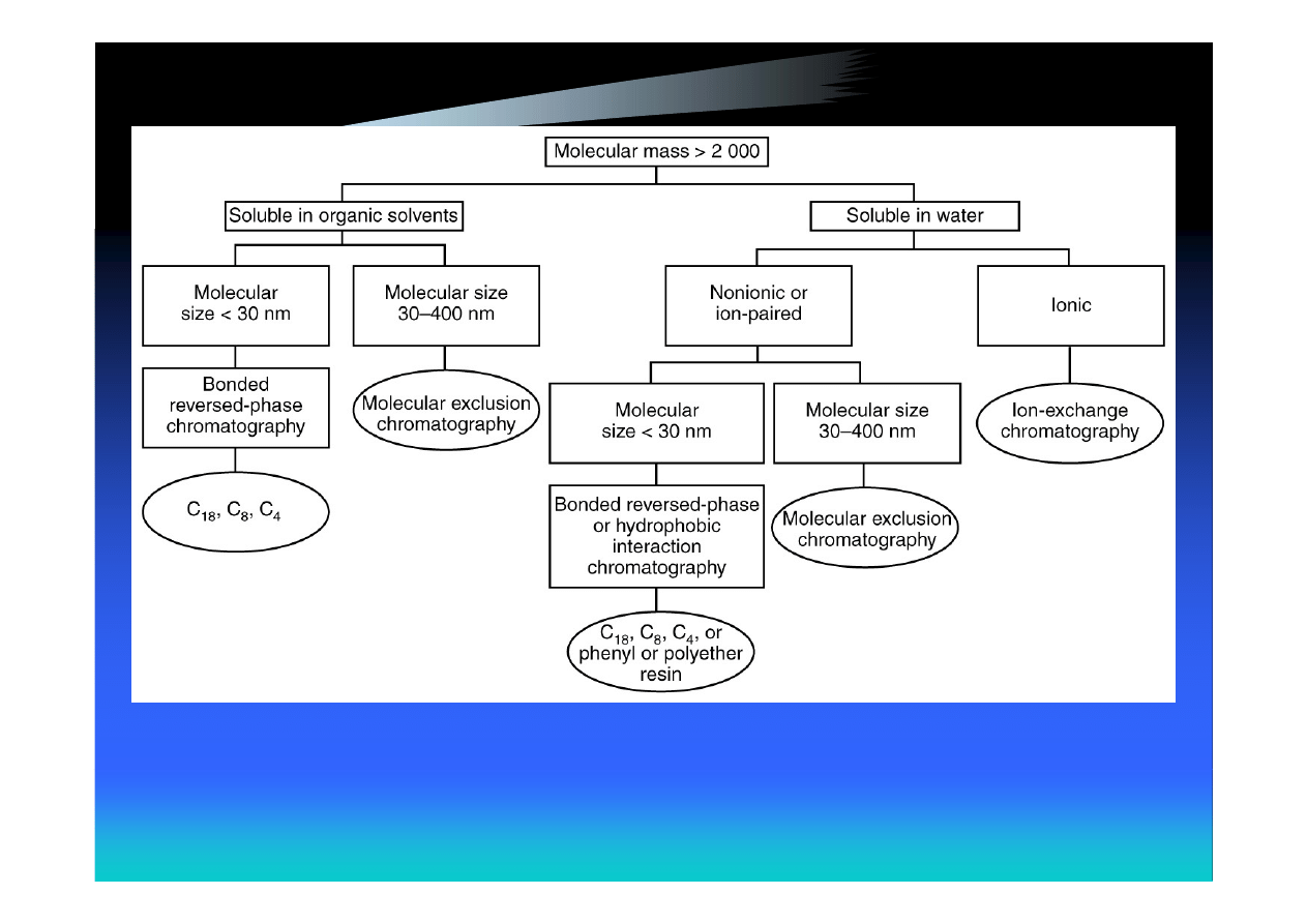
Selecting the Separation Mode
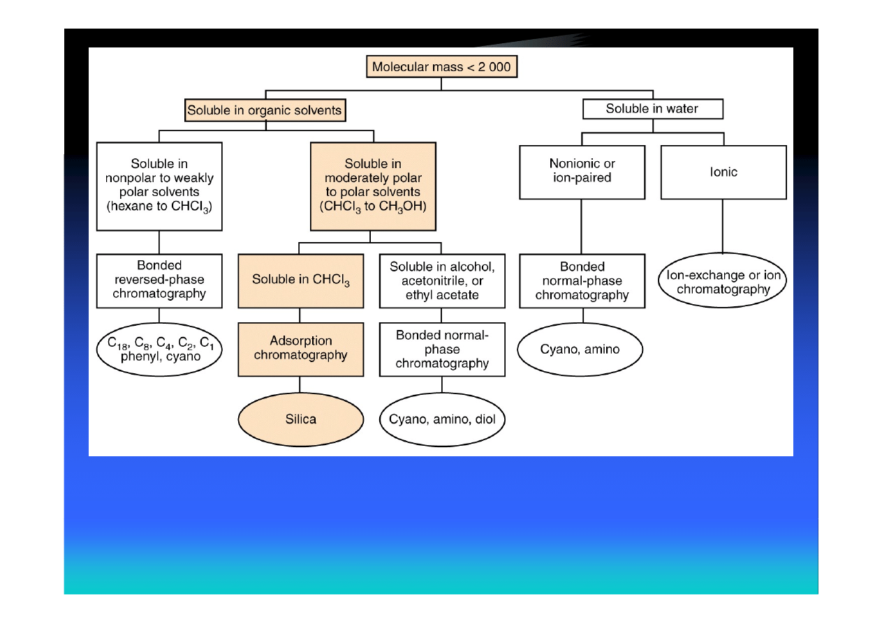
Suppose we have a mixture of small molecules soluble in CH
2
Cl
2

“Green” Technology: Supercritical
Fluid Chromatography
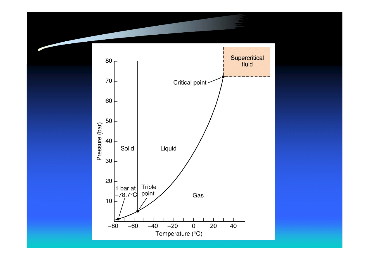
Phase diagram for CO
2
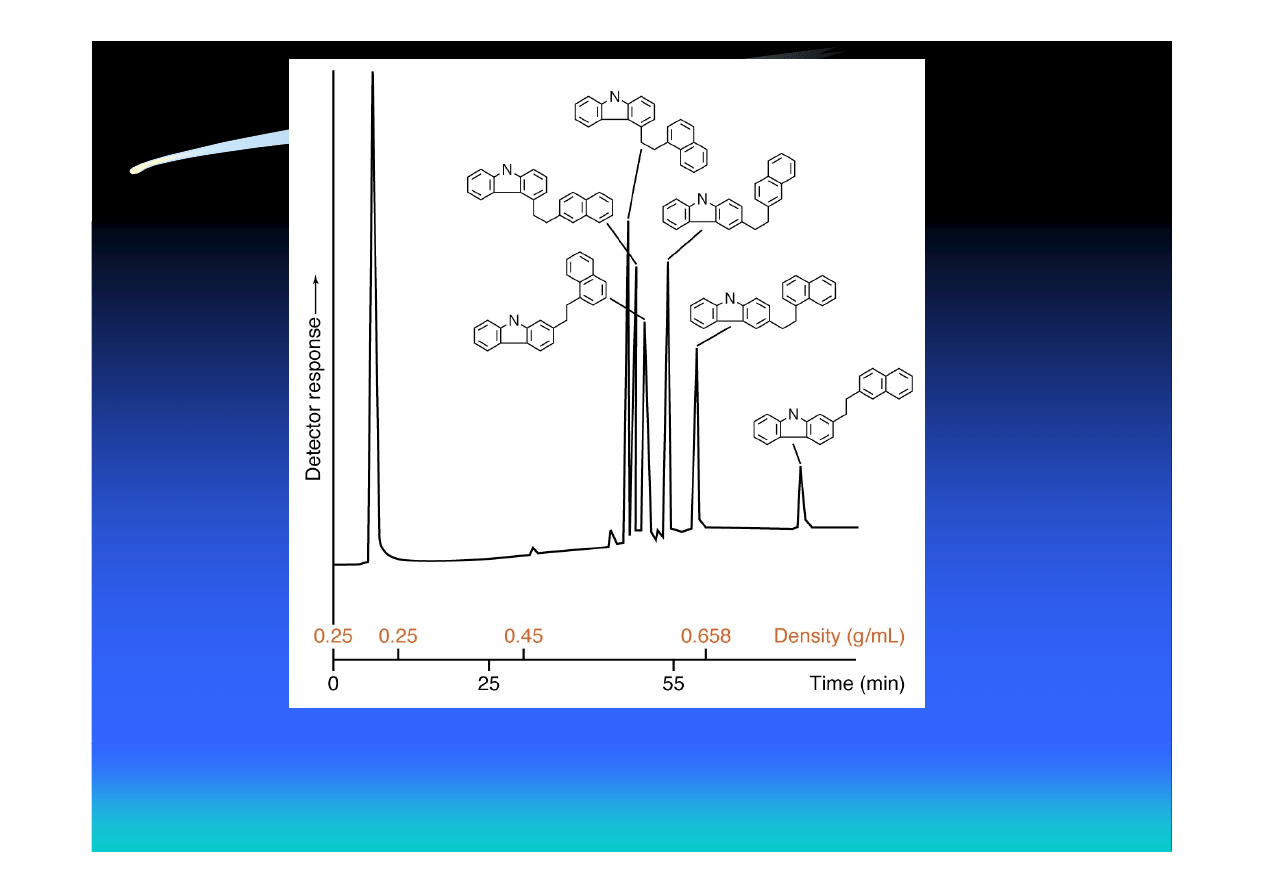
Capillary SFC of aromatic compounds with CO
2
,
using density gradient elution at 140 °C

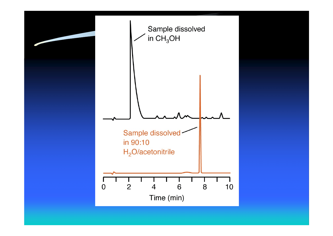
Effect of Sample Solvent
• The sample should be dissolved in a solvent
of lower eluent strength than the mobile
phase or in the mobile phase itself
n-butylaniline

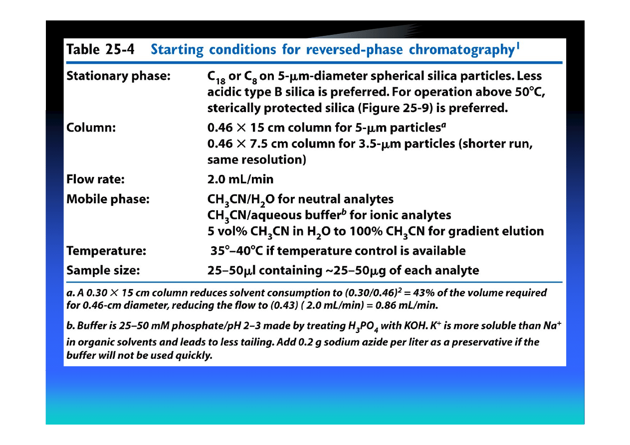
Method Development for Reversed-
Phase Separations
• Adequate resolution of desired analytes
• Short run time (high sample throughput)
• Rugged (not drastically affected by small
variations in conditions)

Initial Steps in Method Development
1. Determine goal
2. Select method of sample preparation
3. Choose detector

Criteria for an Adequate Separation
• Capacity factor 0.5 ≤ k’ ≤ 20
• Resolution R
s
≥ 2
• Operating pressure P ≤ 15 MPa (150 bar)
• 0.9 ≤ asymmetry factor ≤ 1.5

Estimating Dead Time (Volume)
2
2
c
m
Ld
V
≈
F
Ld
t
c
m
2
2
≈
F – flow rate (mL/min)
d
c
2
– column diameter (cm)
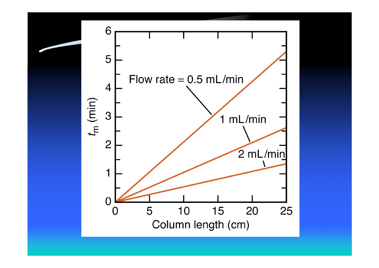
d
c
= 4.6 mm

Optimization with One Organic
Solvent
•
Choice of organic solvent
1. Acetonitrile (low viscosity, low UV cutoff)
2. Methanol (higher viscosity and UV cutoff)
3. Tetrahydrofuran (less usable UV range,
slower equilibration with stationary phase)

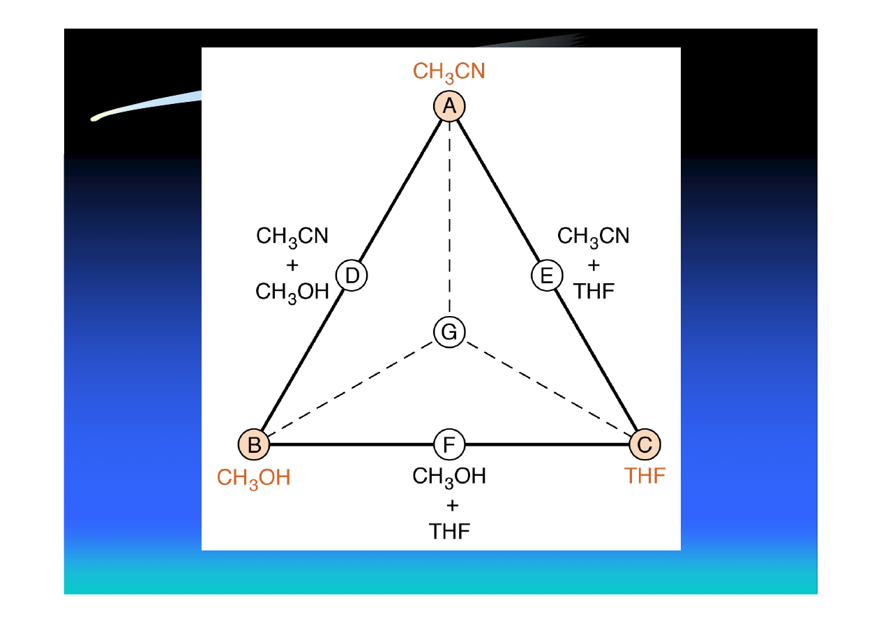
Optimization with Two or Three
Organic Solvents
• Step 1 Optimize the separation with
CH
3
CN/buffer (chromatogram A)
• Step 2 Optimize the separation with
MeOH/buffer (chromatogram B)
• Step 3 Optimize the separation with
THF/buffer (chromatogram C)

Optimization with Two or Three
Organic Solvents (cont.)
• Step 4 Mix the solvents used in A, B, and C, one
pair at a time, in 1:1 proportion (chromatograms
D, E, and F)
• Step 5 Construct a 1:1:1 mixture of the solvents
for A, B, and C (chromatogram G)
• Step 6 If some of the results A through G are
almost good enough, select the best two solvents
and mix the solvents to obtain points between
those two
30% MeCN
70% buffer
40% MeOH
60% buffer
32% THF
68% buffer
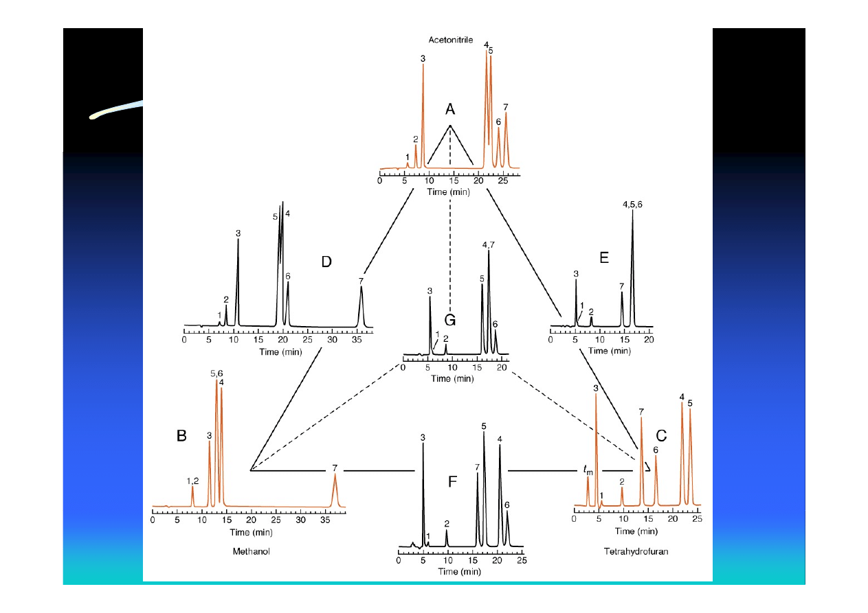
1 – benzyl alcohol
2 – phenol
3 – 3’,4’-dimethoxyacetophenone
4 – m-dinitrobenzene
5 – p-dinitrobenzene
6 – o-dinitrobenzene
7 – benzoin
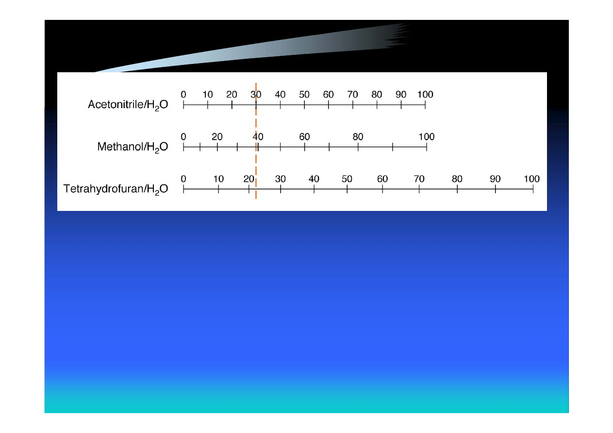
Nomograph showing volume percentage of solvents having
the same eluent strength

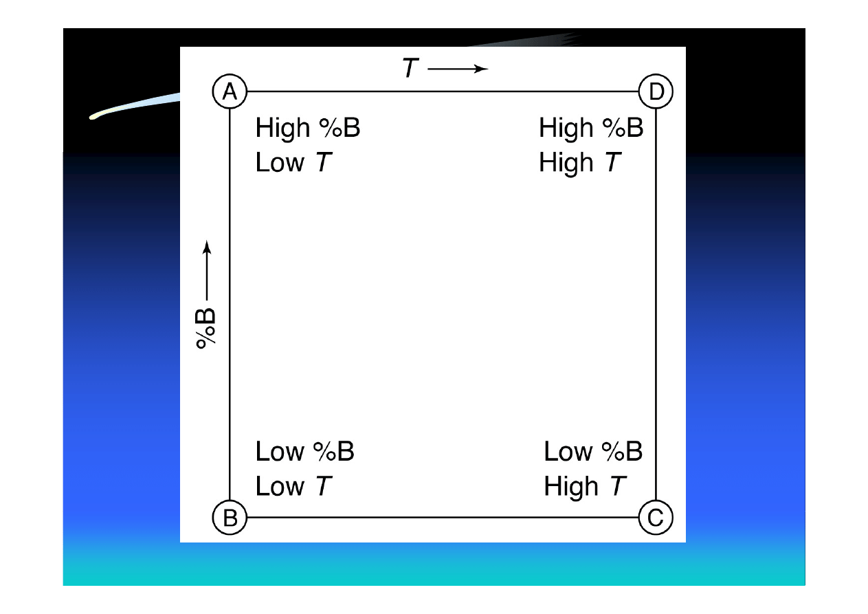
Temperature as a Variable
• Isocratic method development for HPLC
can use solvent composition, %B, and
temperature, T, as independent variables
• %B and T are each varied between selected
low and high values
• From the appearance of chromatograms we
can select intermediate conditions to
improve the separation
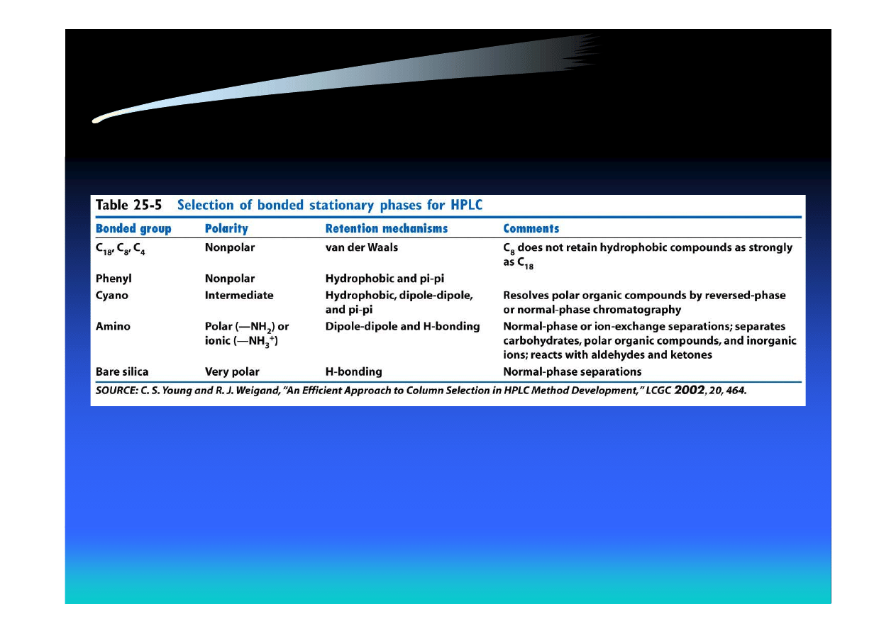
Choosing a Stationary Phase
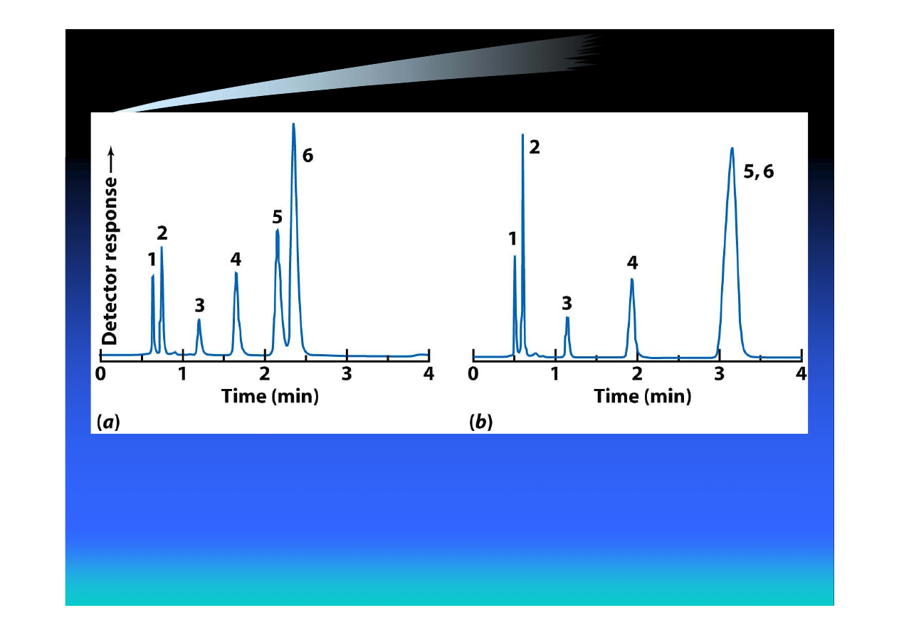
C
18
-silica
phenyl-silica

Order of Steps to Improve Separation
of Two Closely Spaced Peaks
1. Change the solvent strength by varying the
fraction of each solvent
2. Change the temperature
3. Change the pH (in small steps)
4. Use a different solvent
5. Use a different kind of stationary phase

Gradient Elution
• Used in case of general elution problem (GEP) –
mixtures of compounds with a wide range of
polarities
• Run a broad gradient first to decide whether to use
isocratic or gradient elution
• If Δt/t
G
> 0.25, use gradient elution
• If Δt/t
G
< 0.25, use isocratic elution
• Isocratic solvent should have composition applied
to column halfway through the period Δt

Gradient Elution (cont.)
Δt – the difference in the retention time
between the first and last peak in the
chromatogram
t
G
– the gradient time: the time over which
the solvent composition is changed
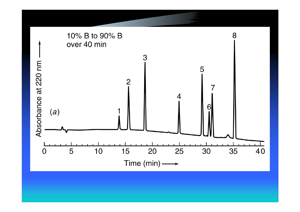

Steps in Gradient Method
Development
1. Run a wide gradient (e.g., 5 to 100% B)
over 40-60 min. From this run, decide
whether gradient or isocratic elution is
best
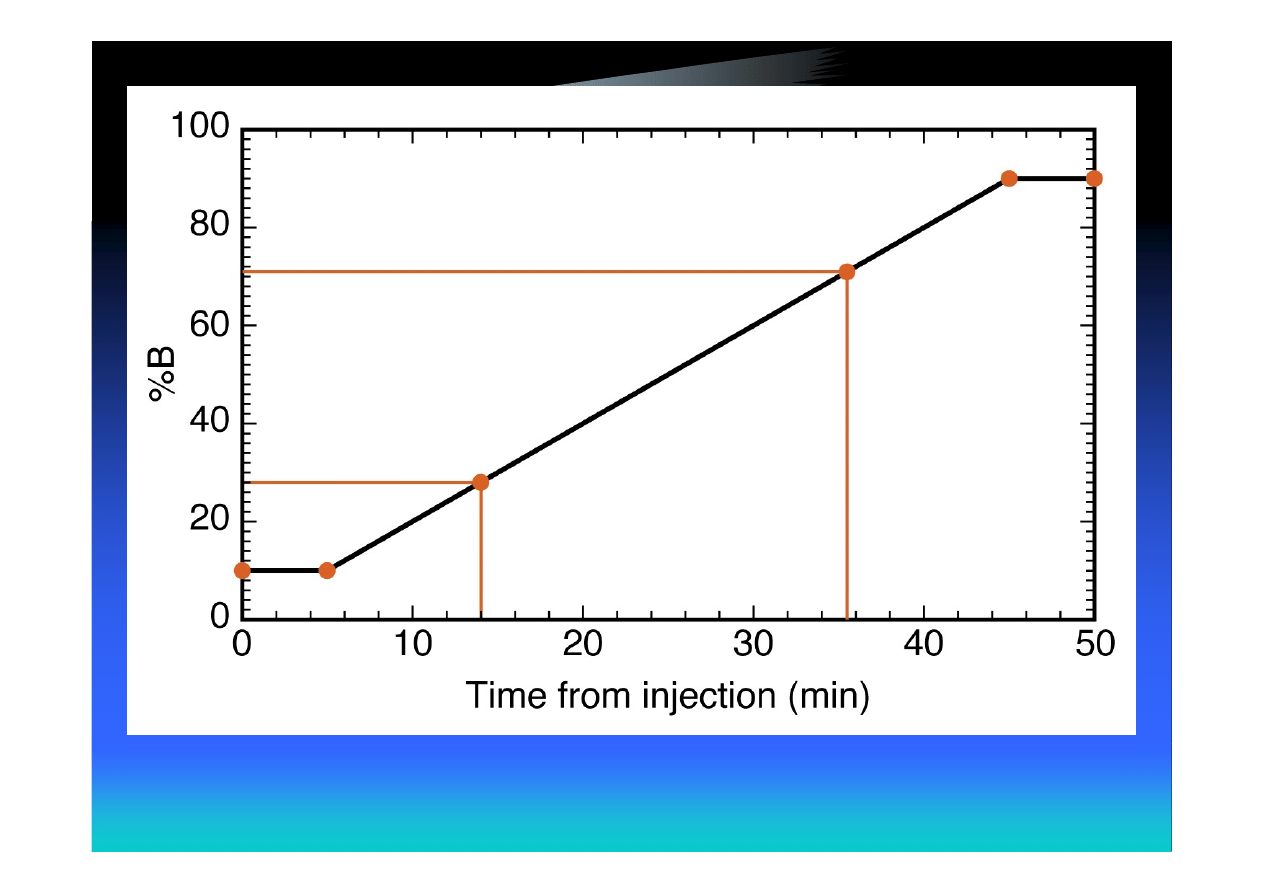
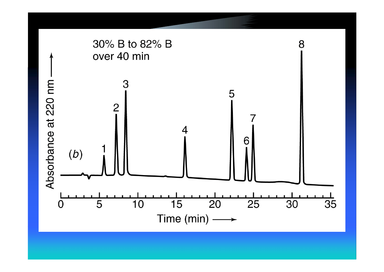
2. If gradient elution is chosen, eliminate
portions of the gradient prior to the first
peak and following the last peak. Use the
same gradient time as in step 1

Steps in Gradient Method
Development (cont.)
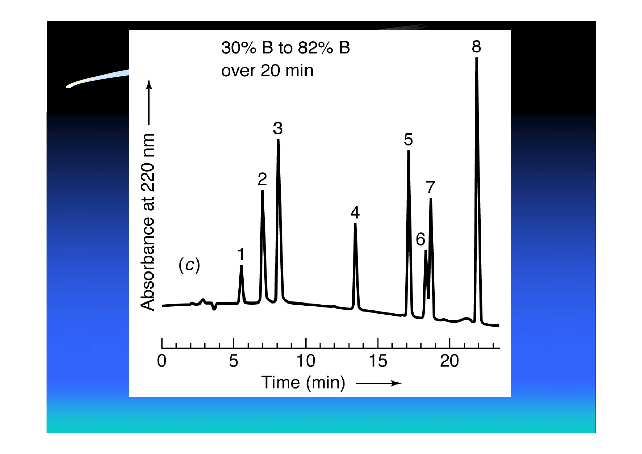
3. If the separation in step 2 is acceptable, try
reducing the gradient time to reduce the
run time
4. If the separation is not acceptable, it can
be improved by going to a segmented
gradient
Document Outline
- Method Development in High-Performance Liquid Chromatography
- The Chromatographic Process
- Plate Height as a Function of Flow Rate
- Number of Theoretical Plates in HPLC
- Smaller Particle Size Leads to
- Required Column Pressure
- The Stationary Phase in HPLC
- Microporous Silica Particles
- Schematic Structure of Silica Gel
- Uses of Silica in HPLC
- Superficially Porous (Pellicular) Particles
- The Elution Process
- Eluotropic Series
- Classification of HPLC Modes
- Elution Modes in HPLC
- Example: Isocratic Separation of Aromatic Compounds by RP HPLC
- Gradient Elution of the Same Mixture of Aromatic Compounds
- Selecting the Separation Mode
- “Green” Technology: Supercritical Fluid Chromatography
- Phase diagram for CO2
- Effect of Sample Solvent
- Method Development for Reversed-Phase Separations
- Initial Steps in Method Development
- Criteria for an Adequate Separation
- Estimating Dead Time (Volume)
- Optimization with One Organic Solvent
- Optimization with Two or Three Organic Solvents
- Optimization with Two or Three Organic Solvents (cont.)
- Nomograph showing volume percentage of solvents having the same eluent strength
- Temperature as a Variable
- Choosing a Stationary Phase
- Order of Steps to Improve Separation of Two Closely Spaced Peaks
- Gradient Elution
- Gradient Elution (cont.)
- Steps in Gradient Method Development
- Steps in Gradient Method Development (cont.)
Wyszukiwarka
Podobne podstrony:
deRegnier Neurophysiologic evaluation on early cognitive development in high risk anfants and toddl
Improvements in Fan Performance Rating Methods for Air and Sound
Improvements in Fan Performance Rating Methods for Air and Sound
Thomas And Patnaik Serial Correlation In High Frequency Data And The Link With Liquidity
A Novel High Performance Utility Interactive Photovoltaic Inverter System
Developments in computer aided dryer selection (Baker, Lababidi)
39 533 547 Carbide Dissolution Rate and Carbide Contents in High Alloyed Steels
High Speed Countercurrent Chromatography
New Developments in HBV Treatment
2014 Kormany Robust UHPLC Separation Method Development
High Performance Fibers
kwasy liquid chromatography
Liquid Chromatography Overview
Balancing Disappointment and Enthusiasm Developments in EU Balkans relations during 2003
A Novel High Performance Utility Interactive Photovoltaic Inverter System
więcej podobnych podstron