1
ELECTRICIAN’S TESTER VR2230
INSTALLATION TESTER VR2240
MULTIFUNCTION TEST INSTRUMENTS
USER INSTRUCTION MANUAL
2
Index:
1.
SAFETY PRECAUTIONS AND PROCEDURES....................................................................4
1.1. Preliminary
instructions...........................................................................................................4
1.2. During
use
1.3. After
use .................................................................................................................................5
2. GENERAL
DESCRIPTION.....................................................................................................6
2.1. Instrument
description ............................................................................................................8
3.
PREPARATION FOR USE...................................................................................................10
3.1.
Initial quality checks..............................................................................................................10
3.2. Power
suppply ......................................................................................................................10
3.3. Battery
Replacement ............................................................................................................10
3.4. Calibration ............................................................................................................................10
3.5. Storage .................................................................................................................................10
4.
DESCRIPTION OF THE ROTARY SWITCH FUNCTIONS ..................................................11
4.1. LOW
Ω: Continuity test of earth, potective and equalising potential conductors..........11
4.1.1. "CAL"
mode ..........................................................................................................................12
4.1.2. Procedure
to
measure
continuity
of equalising potential conductors ....................................14
mode "AUTO", "R+", "R-", "R+TIMER", "R-TIMER"
4.1.3.
Other Error Screens "AUTO", "R+", "R-", "R+TIMER", "R-TIMER" tests ...............................16
4.2. M
Ω: Insulation resistance measurement with the test voltage of 50V, 100V, 250V, 500V
OR
1000V
............................................................................................................................18
4.2.1.
Procedure to measure insulation resistance in any mode.....................................................19
4.2.2.
Special cases which may occur during the tests "MAN", "AUTO", "TIMER"..........................23
4.3. RCD RCD
: tests on RCDS type A OR AC ...................................................24
4.3.1. Procedure
for
RCD testing....................................................................................................27
4.3.2.
Tripping times for general and selective RCDS ....................................................................33
4.3.3.
Other situations which may occur during RCD tests in any working mode............................34
4.4.
Loop ZS /IK: measurement of line impedance E, Fault loop impedance
and calculation of prospective short and fault circuit current........................................38
4.4.1. "P-N"
mode
..........................................................................................................................39
4.4.2. "P-P"
mode ..........................................................................................................................41
4.4.3. "P-PE"
mode ........................................................................................................................42
4.4.4.
Other situations which may occur during loop, ZS/IK tests in any working mode..................44
4.5. R
a15mA
: measurement of earth resistance with
15mA current and calculation of prospective fault current (PFC) ..................................47
4.5.1.
Other situations which may occur during R
A15MA
tests ...................................................49
4.6. Phase
Sequence
Rotation
.............................................................................................52
4.6.1.
Procedure for Phase Sequence testing ................................................................................52
4.6.2.
Other situations which may occur during Phase Sequence tests..........................................54
5.
HOW TO SAVE, RECALL AND CLEAR DATA STORED IN MEMORY (VR2240 Only).....55
5.1. SAVE:
"SAVE"
KEY..............................................................................................................55
5.2.
RECALL: "RCL" KEY............................................................................................................56
5.3.
CLEAR: "CLR" KEY..............................................................................................................57

3
6.
RESETTING THE INSTRUMENT AND DEFAULT PARAMETERS.....................................59
6.1. Reset
Procedure...................................................................................................................59
6.2. Default
Parameters...............................................................................................................59
7.
CONNECTION TO A PC (VR2240 ONLY) ...........................................................................60
8.
PRINTING WITH AN OPTIONAL SERIAL PRINTER (VR2240 ONLY) ...............................61
9.
ACCESSORIES & MAINTENANCE…….……………………………………..…………………62
10. TECHNICAL
SPECIFICATIONS ..........................................................................................63
10.1. Technical
features ................................................................................................................63
10.1.1. Safety
standards...................................................................................................................65
10.1.2. General
specifications ..........................................................................................................65
10.2. Environment .........................................................................................................................66
10.2.1. Environmental
working
conditions ........................................................................................66
10.2.2. EMC .....................................................................................................................................66
11. SERVICE..............................................................................................................................67
4
1. SAFETY PRECAUTIONS AND PROCEDURES
This tester conforms with safety standards BSEN61557 and BSEN 61010-1 relating to
electronic measuring instruments.
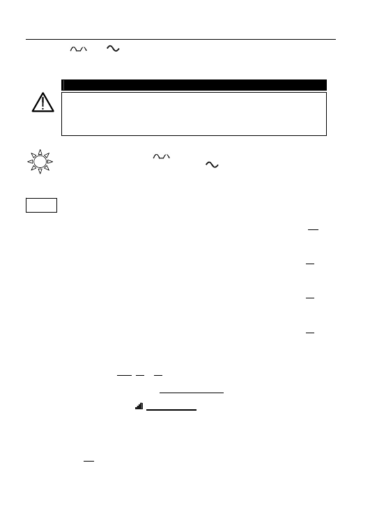
WARNING
For your own safety as well as that of the apparatus you are recommended to
follow the procedures described in this instruction manual and carefully read
all the notes preceded by the symbol
.
Adhere strictly to the following instructions before and during measurements:
)
Do not take measurements in wet environments.
)
Do not perform measurements in environments with explosive gas, fuels or dust.
)
Do not touch the object under test whilst taking measurements.
)
Avoid any contact with exposed metal parts, ends of test leads not in use, circuits, etc.
)
Do not perform any measurements if the instrument is damaged eg: cracked case,
leakage of batteries, absence of display reading etc.
)
Pay careful attention when using test voltages exceeding 25V in places such as
building sites, swimming pools, and damp environments etc. and 50V elsewhere
due to the risk of electric shock.
The following symbols are used in this manual:
Caution: refer to the instructions in this manual; improper use may
damage the tester or its components.
AC Voltage or Current.
Unidirectional pulsating Voltage or Current.
Rotary switch of the instrument.
1.1. PRELIMINARY
INSTRUCTIONS
)
This instrument has been designed for use in environments with pollution degree 2.
)
It can be used for tests on electrical installations with over-voltage category III up to
265V (to Earth).
)
You are recommended to comply with the standard safety practices aimed at:
9
Protecting you against dangerous currents.
9
Protecting the instrument against improper use.
)
Only the leads supplied with the instrument guarantee compliance with safety standards.
They must be in good condition and must be replaced if necessary, with identical models.
)
Do not perform measurements on circuits exceeding the specified voltage limits.
)
Do not perform any measurement under environmental conditions beyond the limits
specified in this manual.
)
Check that batteries have been inserted correctly.
)
Before connecting test leads to the circuit under test, check that rotary switch
position is correct.
)
Check that LCD and rotary switch indicate the same function.
5
1.2. DURING
USE
Read carefully the following recommendations and instructions:
WARNING
Non-compliance with the Warnings and/or Instructions may damage the
apparatus and/or its components or seriously injure the operator
.
)
Before selecting any function disconnect the test leads from the circuit under test.
)
When the instrument is connected to a circuit, do not touch any test lead which is
not being used.
)
Do not carry out resistance measurements in the presence of external voltages:
even though the instrument is protected, too high a voltage may cause damage.
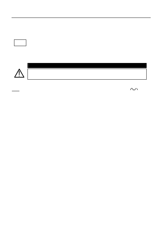
WARNING
If the symbol
is displayed during use, stop testing and replace batteries
The instrument remembers stored data even when batteries are not
installed.
1.3. AFTER
USE
)
When the measurements are completed disconnect the test leads from the
circuit under test and switch OFF the instrument.
)
Remove batteries when the instrument is to be unused for long periods.

6
2. GENERAL DESCRIPTION
This all-in-one tester incorporates continuity, insulation resistance, RCD, earth loop
impedance, phase loop impedances, earth resistance and phase rotation tests.
This unit is smaller and more compact than other machines on the market, which
makes them very comfortable to use in confined and hazardous areas.
The unit can be held comfortably in one hand.
*The Veritest VR2240 can store test results in its internal memory and then download
them to a P.C. via optional software and accessories.
The Veritest is supplied complete with test leads, a protective carry case and user
guide as standard.
Your new instrument will give you accurate and reliable measurements provided
that it is used properly.
These instruments have been designed to give the user the highest level of safety
possible thanks to their innovative design assuring double insulation and over voltage
category III.
)
LOW
Ω: Continuity test of earth, protective and equalizing potential conductors with
test current higher than 200mA and open circuit voltage ranging from 4V to 24V.
)
R
ISO
:
Measurement of insulation resistance with DC test voltage at 50V*,
100V*, 250V, 500V or 1000V.
)
RCD
: Measurement on general and/or selective RCDs AC type (
) of the
following parameters:
9
Tripping time.
9
Tripping current.
9
Contact voltage (U
t
).
9
Overall earth resistance (R
a
).
In this mode the instrument can measure the overall earth resistance
without causing RCD’s to trip
* VR2240 only
7
)
RCD
: Measurement on general and/or selective RCDs A type (
)
of the following parameters:
9
Tripping
time.
9
Tripping
current.
9
Contact
voltage
(U
t
).
9
Overall earth resistance (R
a
).
In this mode the instrument can measure the overall earth
resistance without causing RCD’s to trip.
)
LOOP Z
S
/I
K
:
Measurement of line and fault loop impedance with calculation of
prospective short circuit current.
)
R
a15mA
:
Measurement of fault loop impedance between earth and phase
conductors with current of 15mA and calculation of prospective
short circuit current.
)
:
Indication of phase rotation sequence.
8
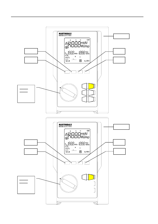
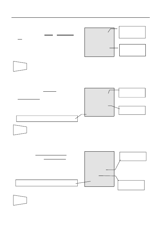
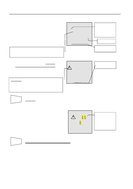
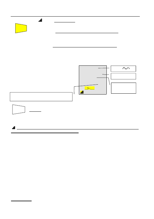
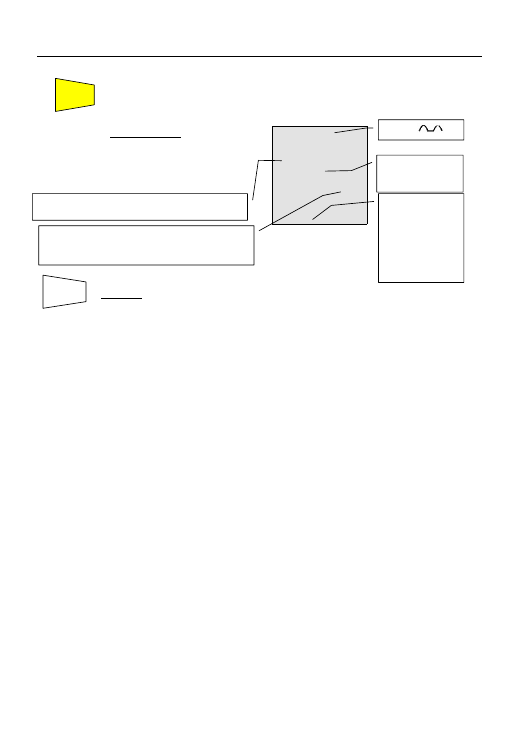
2.1. INSTRUMENT
DESCRIPTION
OFF
ESC
DISPLAY
SAVE
RECALL
START
STOP
CLEAR
OFF
ESC
DISPLAY
SAVE
RECALL
START
STOP
CLEAR
Rotary
switch:
Rotate to
select the
function
3
1
FUNC
U
n
/I
∆n
S ▲
U
L
▼
GO
ESC
SAVE
DISP
CLR
RCL
GO
DISP
VERITEST VR2240
VERITEST VR2230
Rotary
switch:
Rotate to
select the
function
1
3
U
n
/I
∆n
FUNC
S ▲
U
L
▼
VR2240
VR2230
9
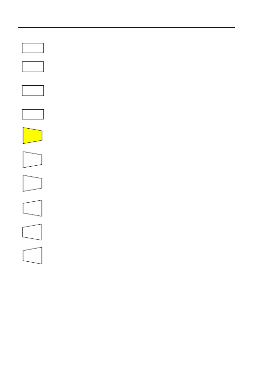
Description of controls
)
Multifunction key to select measuring modes.
)
Key for selection of differential currents during tests of RCDs or rated
voltages during tests of insulation resistance (depends on the selected
measurement) with the rotary switch.
)
Key for selection of RCD type (General or Selective) or to increase the
test duration interval or to scroll through the results of the stored tests.
)
Key for selection of contact voltage limit or to decrease the test duration
interval or to scroll through the results of the stored tests.
)
Key to start or to stop tests.
*
)
*Key to quit the function of selected mode
*
)
*Key to save tests
*
)
*Key to recall stored tests
)
Key to scroll between single and multiple test results
(Eg: RCD auto) which have been stored.
*
)
*Key to delete the stored tests
* VR2240 only
GO
U
L
▼
ESC
SAVE
RCL
DISP
CLR
FUNC
U
n
/I
∆n
S ▲
10
3. PREPARATION FOR USE
3.1. INITIAL
QUALITY
CHECKS
This instrument has been checked mechanically and electrically prior to shipment.
Every care has been taken to ensure that the instrument reaches you in perfect condition.
In the unlikely event that you have to send the instrument back to us, please follow the
instructions detailed in section 11.
3.2. POWER
SUPPLY
This instrument is supplied with six batteries model 1.5V – LR6 – AA – AM3 – MN 1500
included as standard
3.3. BATTERY
REPLACEMENT
When the symbol
is displayed the batteries should be replaced.
WARNING
Before replacing batteries make sure that all test leads have been disconnected
from input terminals. The VR2240 is capable of storing data when batteries
are removed
1. Switch OFF the instrument.
2. Remove all of the test leads from the input terminals.
3. Unscrew the fixing screws from the battery compartment cover and remove it.
4. Remove all batteries replacing them with 6x of the same type
(1.5V – LR6 – AA – AM3 – MN 1500) observing correct polarity.
5. Fix the screws on the battery compartment cover.
3.4. CALIBRATION
This Instrument is shipped to you manufactured within the specification shown in
section 10 of this manual. Performance within the specification is guaranteed for
one year. Annual re-calibration is recommended. A Calibration certificate for this
instrument is available as a chargeable extra and is not supplied as standard.
Please contact us on 01923 441717 for more details.
3.5. STORAGE
In order to ensure the accuracy of measurements, after a period of storage
in extreme environmental conditions, wait for the instrument to acclimatize
back to normal measuring conditions (see environmental specifications listed
in paragraph 10.2.1).
11
4. DESCRIPTION OF THE ROTARY SWITCH FUNCTIONS
4.1. LOW
Ω: CONTINUITY TEST OF EARTH, PROTECTIVE AND EQUALIZING
POTENTIAL CONDUCTORS
The measurement is performed with a test current higher than 200mA and open circuit
voltage ranging from 4 to 24V DC according to BSEN 61557-4 and VDE 0413 part 4.
WARNING
Before carrying out the continuity test make sure that there is no voltage
at the ends of the conductors under test.
Turn the switch to the LOW
Ω position.
FUNC key is used to select one of the following measuring modes
(which can be shown in rotation when pressing the key):
)
AUTO Mode (the instrument carries out two measurements one with
positive polarity R+ and one with negative polarity R-, and displays their
average value R
avg
). This mode is recommended for the continuity test.
)
R + Mode (measurement with positive polarity, red cable will be
positive polarity and black cable will be negative polarity).
)
R - Mode (measurement with negative polarity, black cable will be
positive polarity and red cable will be negative polarity).
)
R + TIMER Mode (measurement with positive polarity with adjustable
test duration). The operator can set a measuring time long enough to
permit them to move the conductors while the instrument is carrying
out the test so detecting bad connections.
)
R - TIMER Mode (measurement with negative polarity with adjustable
test duration). In this case the operator can set a measuring time long
enough to permit them to move the protective conductors while the
instrument is carrying out the test so detecting bad connections.
)
CAL Mode (compensation for the resistance of the test leads).
Note: If the resistance is lower than 16
Ω (including the resistance of the leads) the
continuity test is performed with a current higher than 200mA. If the resistance
is higher than 16
Ω the continuity test is performed with a current of 40mA.
FUNC
12
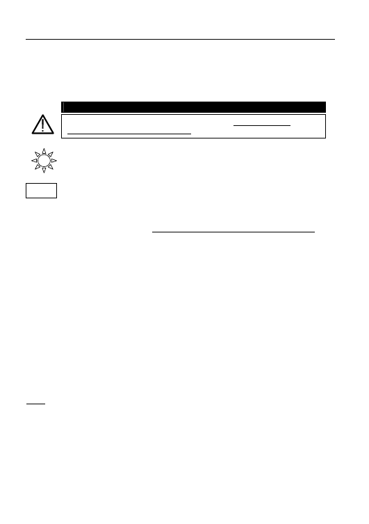
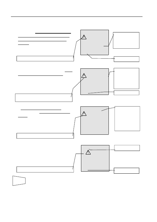
4.1.1. "CAL" MODE
1. Select CAL mode with the FUNC key.
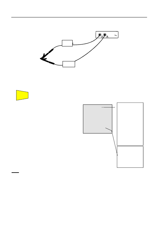
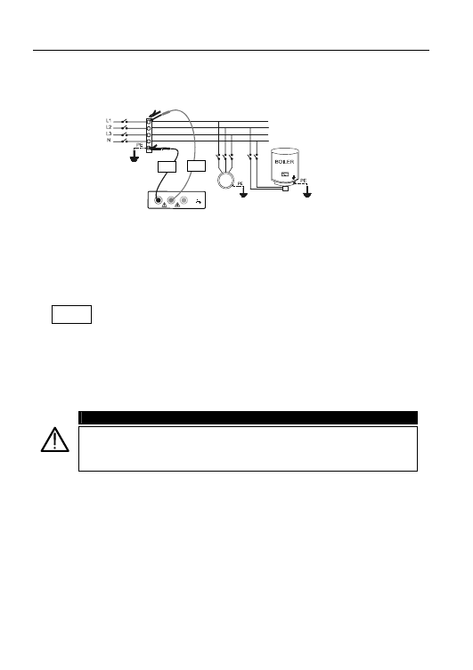
2. Connect the Red and Black cables to the instrument input terminals P and N respectively:
E
L2
N
L3
P
L1
(P)
CAT III
INPUT MAX
440 V P-N-E
250 V
Linking of instrument terminals during calibration procedure.
3. Connect the crocodile clips to the cable terminals.
4. Short-circuit the measuring cable ends making sure that the conductive parts of the
crocodile clips make good contact with each other (see picture).
5. Press the GO key. The instrument carries out the calibration.
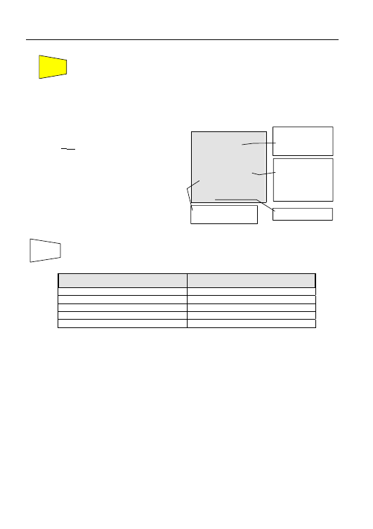
)
CAL
LOW
Ω
0.00
Ω
203
mA
At the end of the test
the result is stored and
used as an OFFSET (it
is subtracted from
any continuity test
carried out) for all
subsequent
measurements until a
new calibration is
carried out.
This screen is displayed for only 2 seconds
then the instrument beeps twice (indicating
that the calibration is completed) and displays
the default screen for the LOW
Ω test under
AUTO mode.
Note: The instrument compensates for leads with resistance below 5
Ω.
CAL:
indicates that the
instrument has a
stored value for
the resistance of
the test leads; this
symbol remains
on the display
for any further
measurements
even when the
unit is switched
off and on again.
Current supplied
by the instrument
during the
calibration
procedure.
GO
Black
Red
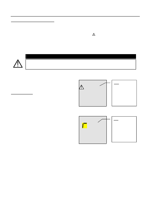
13
LEADS USED FOR THE TEST
Before any measurement always make sure that
the unit has been calibrated with the test leads in
use. During a continuity test, if the resistance
value measured is less the calibration offset value
stored, the symbol is displayed as well as
blinking “CAL” (see 4
th
screen in paragraph 4.1.3).
This indicates that the calibration stored in the
instrument memory may be for leads other than
those in use, so a new calibration is required.
Never disconnect the test leads while “Measuring” is displayed.
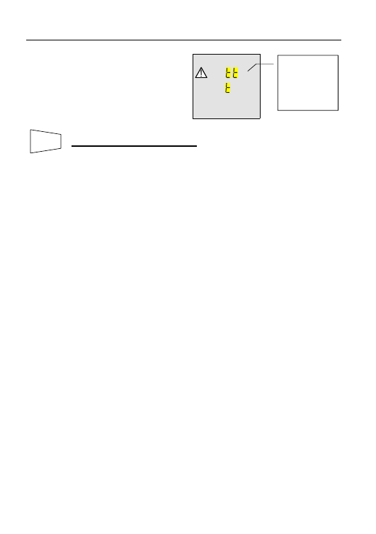
4.1.1.1. Procedure to remove stored calibration and cal symbol
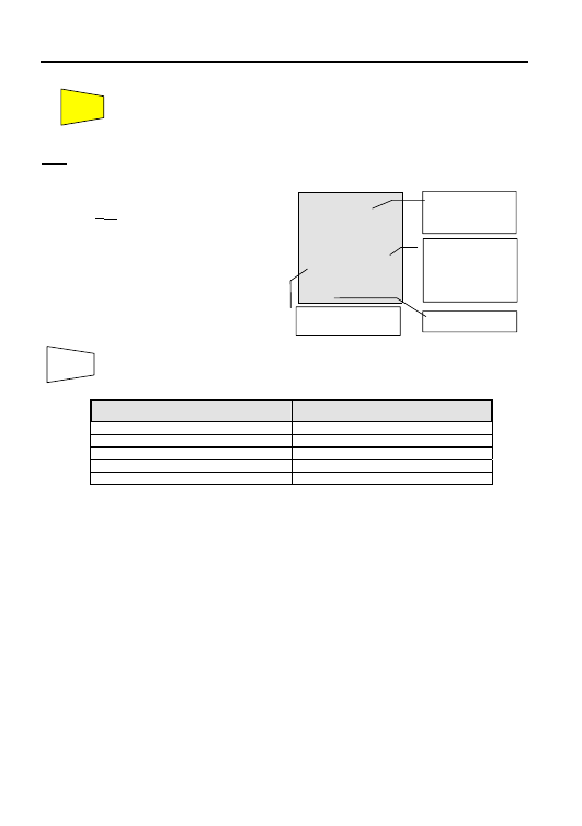
LOW
Ω
>5.00
Ω
cal
Measuring
To remove a stored calibration (and the
symbol CAL) you need to perform a
calibration procedure with a resistance
higher than 5
Ω (for Example with
disconnected test leads). When this
procedure is carried out the screen
opposite is displayed first, followed by the
screen below:
LOW
Ω
es
cal
The screen opposite is displayed for 2
seconds, after which the instrument emits a
long sound signal and then displays the
default screen for the LOW
Ω test under
AUTO mode without displaying the symbol
CAL.
>5
Ω: Indicates
that the
instrument
measured a
resistance higher
than 5
Ω so it will
proceed with
reset procedure.
rES: Indicates
that the
instrument
removed
(RESET) the
stored calibration
& cal symbol
14
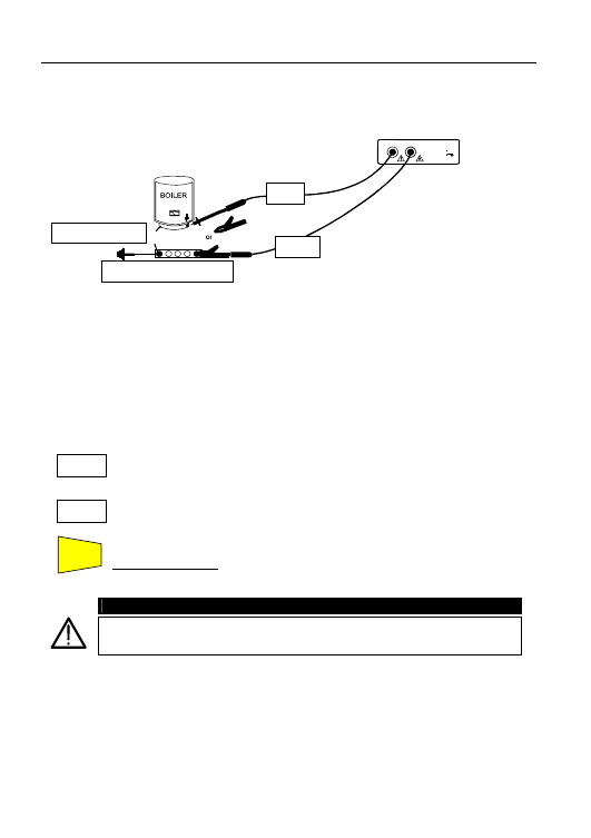
4.1.2. Procedure to measure the continuity of conductors "AUTO", "R+", "R-",
"R+TIMER" and "R-TIMER"
1. Select the desired mode with the FUNC key.
2. Connect the Red and Black cables to the instrument input terminals P and N respectively.
E
L2
N
L3
P
L1
(P)
CAT III
INPUT MAX
440 V P-N-E
250 V
Connections during LOW
Ω test.
3. Connect the two crocodile clips to the test lead terminals.
4. Short-circuit the measuring lead ends making sure that the conducting parts of the
crocodile clips make good contact with each other. Press the GO key. If the
instrument displays a resistance value other than 0.00 repeat the
instrument calibration (see paragraph 4.1.1).
6. Connect the crocodile clips to the conductors on which the continuity test is to
be carried out (see previous picture).
7. If "R+TIMER" or "R-TIMER" mode is selected use the following keys to
select the duration of the test:
Press this key to increase the duration of the test (Tmax=15 seconds).
Press this key to decrease the duration of the test (Tmin=3 seconds).
8. Press
the
GO key. The instrument performs the measurement.
In R+/R- Timer mode press GO key again if the test is to be stopped.
WARNING
Never disconnect the test leads while “Measuring” is displayed.
S ▲
U
L
▲
GO
Red
Black
Main Earth Connector
P-E Conductor
15
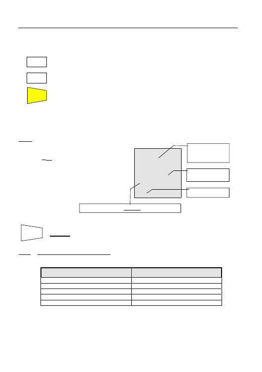
4.1.2.1. "AUTO"
Mode
)
CAL
LOW
Ω
1.07
Ω
219
mA
AUTO
At the end of the test, if the average
resistance value Ravg is lower than
5
Ω the instrument emits a double
sound signal indicating the positive
outcome of the test and displays a
screen similar to this.
*
*The test can be stored by pressing the SAVE key twice
4.1.2.2. "R+" or “R-" Mode
)
CAL LOW
Ω
1.07
Ω
219
mA
R+
R-
At the end of the R+ or R- test if a
resistance value
lower than 5
Ω was detected, the
instrument emits a double sound
signal indicating a successful
outcome of the test and displays a
screen similar to this.
*
*The test can be stored pressing the SAVE key twice
4.1.2.3. "R+TIMER" or “R-TIMER" Mode
)
CAL LOW
Ω
1.08
Ω
219
mA
5
s
R+
R-
TIMER
If during the R+Timer or R-Timer test a
resistance value lower than 5
Ω is
detected, the instrument (after the set
time has elapsed) emits a double sound
signal indicating the positive outcome
of the test and displays a screen similar
to this.
*
*The test can be stored pressing the SAVE key twice
* VR2240 only
Average test
current value
Iavg.
Average
resistance value
Ravg.
Duration time of
the test
Resistance value
R+ or R-.
Value of test
current I+ or I-.
The symbols R
+
or R
-
are displayed.
The symbols R
+
or R
-
are displayed.
Value of the test
current I+ or I-.
SAVE
SAVE
SAVE
16
4.1.3. Error screens which may occur during "AUTO", "R+", "R-", "R+TIMER", "R-
TIMER" tests
)
CAL LOW
Ω
5.75
Ω
216
mA
5
s
AUTO
If a value of Ravg or R+ or R- higher
than or equal to 5
Ω but lower than
99.9
Ω (9.99Ω in R+TIMER and R-
TIMER) was detected, at the end of the
test the instrument emits a long sound
signal and displays a screen similar to
this.
)
CAL LOW
Ω
>99.9
Ω
- - -
mA
AUTO
If in modes AUTO, R+, R- and a Ravg
or R+ or R- higher than 99.9
Ω was
detected, at the end of the test the
instrument emits a long sound signal
and displays a screen similar to this.
)
CAL LOW
Ω
>9.99
Ω
---
mA
4
s
R+
TIMER
If R+TIMER or R-TIMER Mode was
selected and a R+ or R- higher than
9.99
Ω was detected, the instrument
emits an intermittent sound signal
during the test, a long sound signal
at the end of the test and displays a
screen similar to this.
)
CAL LOW
Ω
0.00
Ω
219
mA
AUTO
If the R
MEASURED
(measured resistance)
-R
CALIBRATION
(minus test lead
resistance) is less than 0
Ω the
instrument displays a screen similar to
this.
*
*The tests can be stored by pressing the SAVE key twice
* VR2240 only
WARNING: value of R
avg
higher than 5
Ω
99.9
Ω is the
maximum value
which can be
measured in the
LOW
Ω AUTO or
R+ or R-mode.
9.99
Ω is the
maximum value
which can be
measured in
LOW
Ω,
R+TIMER or R-
TIMER mode.
AUTO mode.
AUTO mode.
WARNING: value of R
avg
or R+ or R- is too
high.
WARNING: value of R+ or R- is too high.
Only if mode
R+TIMER or R-
TIMER was
selected.
Blinking CAL.
WARNING: R
MEASURED
-R
CALIBRATION
< 0
AUTO mode.
SAVE
17
)
CAL LOW
Ω
A
VOL AG
If a voltage higher than 10V is detected
at the test leads, the instrument does
not carry out the test and displays the
screen alongside for 5 seconds. Then
the instrument displays the screen for
the previously selected test mode
LOW
Ω under AUTO mode.
*
THIS RESULT CANNOT BE SAVED.
* VR2240 only
WARNING: the
test was not
performed
because of
excessive voltage
at the terminal
ends.
SAVE
18
4.2. M
Ω:
INSULATION RESISTANCE MEASUREMENT WITH TEST VOLTAGE OF
50V*, 100V*, 250V, 500V OR 1000V
The measurement is carried out in accordance with BSEN 61557-2 and VDE 0413 part 1.
Before carrying out the insulation test make sure that the circuit under test is
not energized and all the loads are disconnected.
Turn the switch to M
Ω position.
The FUNC key is used to select one of the following measuring modes (which
can be shown in rotation when pressing the key):
)
MAN Mode (minimum test time of 10 seconds, or for as long as the GO key
is held). Recommended test.
)
AUTO Mode (the test ends when the measured value becomes stable).
This test can be used if the installation has capacitance which must be
charged to evaluate the real insulation resistance.
)
TIMER Mode (test duration depending on the selected interval (from 10 to
999 seconds). This test can be used if a minimum measuring time is
required.
* VR2240 only
FUNC
19
4.2.1. Procedure to measure insulation resistance
1. Select the desired mode using the FUNC key.
2. Connect the Red and Black test leads to the instrument input terminals P and N
respectively,
M
E
L2
N
L3
P
L1
(P)
CAT III
INPUT MAX
440 V P-N-E
250 V
Example insulation test between phase (#1) and earth
in a 3 phase electrical installation using test leads.
3. Connect the instrument terminals to the circuit which is to be subjected to the insulation
test after disconnecting the circuit under test from the supply and all relevant loads
(see previous picture).
4. Using
the
U
n
/I
∆n
Key, select the test voltage suitable for the type of test
being carried out (see table).
5.
The values available are:
• 50V* (test on telecommunication systems)
• 100V*
• 250V
• 500V
• 1000V
If “Measuring” is displayed the instrument is carrying out the measurement.
During this stage do not disconnect the test leads as the circuit under test
may remain charged at a dangerous voltage due to the capacitance of the
installation. The instrument discharges any stored energy after each test.
* VR2240 only
U
n
/I
∆n
Black
Red
20
4.2.1.1. "MAN"
Mode
6. Press
the
GO key.
The instrument performs the test lasting for:
9
Minimum 10 seconds if the key is pressed and released within 5 seconds.
9
Or until the key is released.
)
R
ISO
1.00
M
Ω
500
V 20
s
MAN
At the end of the test, if the resistance
value R
ISO
detected is lower than R
MAX
(see table below), the instrument beeps
twice indicating the positive outcome
of the test and displays a screen similar
to this.
*
*The test can be stored by pressing the SAVE key twice
Test Voltage
R
MAX
= Maximum resistance value
50VDC*
99.9M
Ω
100VDC*
199.9M
Ω
250VDC
499M
Ω
500VDC
999M
Ω
1000VDC
1999M
Ω
* VR2240 only
Rated voltage value
selected for the test.
Test duration.
In this case the
GO key has been
pressed for 20
seconds.
Manual mode.
SAVE
Insulation
resistance value
R
ISO.
GO
21
4.2.1.2. "AUTO"
Auto
6. Press
the
GO key. The instrument performs the measurement ending
when the measured value stabilizes.
Note: Press the GO key again to stop the test
*
*The test can be stored pressing the SAVE key twice
Test Voltage
R
MAX
= Maximum resistance value
50VDC*
99.9M
Ω
100VDC*
199.9M
Ω
250VDC
499M
Ω
500VDC
999M
Ω
1000VDC
1999M
Ω
* VR2240 only
)
R
ISO
1
.
18
M
Ω
500
V 18
s
AUTO
At the end of the test, if the resistance
value R
ISO
detected is lower than R
MAX
(see following table) the instrument
beeps twice indicating the positive
outcome of the test and displays a
screen similar to this.
Insulation
resistance value
R
ISO.
Automatic mode.
Rated voltage value
selected for the test.
Test duration.
In this case the
measurement
stabilized after 18
seconds.
SAVE
GO
22
4.2.1.3. "TIMER" Mode
6. When using "TIMER" mode, use the following keys to set the duration time of the test:
press this key to increase the duration of the test (Tmax=999 seconds).
press this key to decrease the duration of the test (Tmin=10 seconds).
7. Press
the
GO key.
The instrument performs the test which will end when the set time has elapsed.
999 seconds
→ Maximum value of the test duration.
10
seconds
→ Minimum value of the test duration.
Note: Pressing the GO key again immediately stops the test.
)
R
ISO
2
.
07
M
Ω
500
V 20
s
TIMER
At the end of the test, if the resistance
value R
ISO
detected is lower than R
MAX
(see following table), the instrument
beeps twice indicating the positive
outcome of the test and displays a
screen similar to this.
*
SAVING:
*The test can be stored pressing the SAVE key twice
Note: The maximum resistance value R
MAX
which can be measured in mode M
Ω depends
on the rated voltage selected for the test:
Test Voltage
R
MAX
= Maximum resistance value
50VDC*
99.9M
Ω
100VDC*
199.9M
Ω
250VDC
499M
Ω
500VDC
999M
Ω
1000VDC
1999M
Ω
* VR2240 only
Timer mode.
Duration of the
set test.
Insulation
resistance value
R
ISO.
Rated voltage value selected for the Timer test.
SAVE
S ▲
U
L
▼
GO
23
4.2.2. Other screens which may appear during "MAN", "AUTO" & "TIMER" tests
)
R
ISO
>999
M
Ω
500
V 20
s
MAN
If a value of R
ISO
higher than R
MAX
was
detected (depending on the selected
voltage, the instrument emits a double
beep at the end of the test indicating
the positive outcome to the test and
displays a screen similar to this.
)
R
ISO
0.01
M
Ω
500
V 20
s
MAN
If a test is performed at a voltage
lower than the set rated voltage, at
the end of the test the instrument emits
a long single beep and displays a
screen similar to this.
*
SAVING:
*The test can be stored pressing the SAVE key twice
)
R
ISO
A
VOL AG
If the terminal voltage is higher than
30V, the instrument does not perform
the test, and displays the screen
alongside for 5 seconds. Then it shows
the default screen for the R
ISO
test
under AUTO mode.
*
THIS RESULT CANNOT BE SAVED.
* VR2240 only
WARNING: the
test was not
carried out.
Check that the
circuit is not
energised.
The symbol ">"
means that the
resistance value
R
ISO
is higher than
R
MAX
Test duration
Selected mode
MANUAL
Selected mode
MANUAL
WARNING: the insulation resistance test R
ISO
was
performed at a voltage value lower than the set
rated voltage. This occurs under low insulation*
conditions or in the presence of capacitance on
the installation. *See technical specification.
Maximum resistance value which can be
measured (999M
Ω is displayed if a rated
voltage of 500V was selected).
SAVE
SAVE
24
4.3. RCD RCD
:
TESTS ON TYPE A OR AC RCD’S
The test is performed according to BSEN 61557-6, BSEN61008, BSEN61009,
BSEN60947-2 B 4.2.4 and VDE 0413 part 6.
WARNING
The automatic check of the RCD causes tripping of the RCD itself. Therefore
check that there is no power or load connected downstream which could
be affected by the installation switching off.
It is advisable to disconnect all the loads connected downstream of the RCD as
they could add leakage currents so making the test results void.
Turn the switch to RCD
(RCDS type A sensitive to pulsating
leakage current DC sensitive) or RCD
(RCDS type AC sensitive to
sine leakage current) position:
The FUNC key is used to select one of the following measuring modes
(which can be shown in rotation when pressing the key)
)
MAN x ½ the instrument performs the test with a leakage current at 1/2
the value of the rated current indicated, with a leakage current in phase
with the voltage or phase shifted by 180° with respect to the voltage.
)
MAN x 1 the instrument performs the test with a leakage current at 1x
the value of the rated current indicated, with a leakage current in phase
with the voltage or phase shifted by 180° with respect to the voltage.
)
MAN x 2 the instrument performs the test with a leakage current at 2x
the value of the rated current indicated, with a leakage current in phase
with the voltage or phase shifted by 180° with respect to the voltage.
)
MAN x 5 the instrument performs the test with a leakage current at 5x
the value of the rated current indicated, with a leakage current in phase
with the voltage or phase shifted by 180° with respect to the voltage.
)
AUTO the instrument performs the test automatically with a leakage
current at 1/2x, 1x & 5x the value of the rated current indicated with the
leakage current in phase with the voltage or phase shifted by 180° with
respect to the voltage. Recommended test.
)
*RAMP MODE (VR2240 ONLY) the instrument performs the test
with a steadily increasing leakage current, with the leakage current
in phase with the voltage or phase shifted by 180° with respect to
the voltage. Use this test to measure the tripping current.
)
Mode U
t
the instrument performs the test with a leakage current equal to
1/2 the value of the rated current indicated and calculates the contact
voltage as well as the R
a
earth resistance with a leakage current in
phase with the voltage or phase shifted by 180° with respect to the voltage.
)
Readings
below 1Ω are displayed as 1Ω
FUNC
25
Note: According to standard practice it is recommended to perform RCD tests both
with phase at 0° and with phase at 180°. Therefore the test must be repeated
for both phase values of test current. If the RCD under test is of a type sensitive to
both AC and unidirectional pulsing leakage currents, it is advisable to perform the
test both with sine wave and unidirectional pulse current with phase 0° and 180°.
The key U
n
/I
∆n
is used to select one of the following rated tripping currents
of the RCD (which can be shown in rotation when pressing the key):
)
10mA.
)
30mA.
)
100mA.
)
300mA.
)
500mA.
The key S▲ is used to activate the test for general or selective RCDs:
)
if the test is performed for selective (time delayed) RCDs the symbol
S
must be displayed.
)
if the test is performed for general RCDs the symbol
S
must NOT be
displayed.
The option for testing selective RCDs requires an interval between tests of 60
seconds (30 seconds in case of tests at ½ I
∆n
). A timer is displayed indicating
the waiting time before the instrument performs the test automatically.
Example:
Testing a selective RCD with a rated current of I
∆n
=30mA
a) the instrument performs the test at ½ I
∆n
0°. If the RCD
passed the test, “OK” is displayed and the RCD does not trip.
b) The instrument performs the test at ½ I
∆n
180°. If the RCD
passed the test, “OK” is displayed and the RCD does not
trip. At this stage 30 seconds must elapse before performing
the next test.
c) The instrument performs the test at I
∆n
0°. If the RCD passed
the test, “OK” is displayed and the RCD trips and the blinking
symbol “rcd” is displayed. The operator should switch on the
RCD. After the RCD trips at least 60 seconds must elapse
before performing the next test.
d) The instrument performs the test at I
∆n
180°. Follow the
same procedure as described under c).
e) The instrument performs the test at 5xI
∆n
0°. Follow the
same procedure as described under c).
f) The instrument performs the test at 5xI
∆n
180°. Follow the
same procedure as described under c). The test is completed.
In AUTO mode, the operator should switch the RCD on whenever the
instrument displays the blinking symbol “rcd” signaling the RCD has tripped.
U
n
/I
∆n
S ▲
26
Note: On selective RCDs it is possible to carry out the following tests ”Man ½ I
∆n
”, ”Man 1
I
∆n
”, ”Man 2 I
∆n
”, ”Man 5 I
∆n
”, “AUTO”.
The key U
L
▼ is used to select one of the following limit values for the
contact voltage (which can be shown in rotation when pressing the key):
)
50V (default)
)
25V.
WARNING
Never disconnect the test leads while “Measuring” is displayed.
Note: ”Man 5x I
∆n
” and “AUTO” test modes are NOT available for RCD type A
500mA.
U
L
▼
27
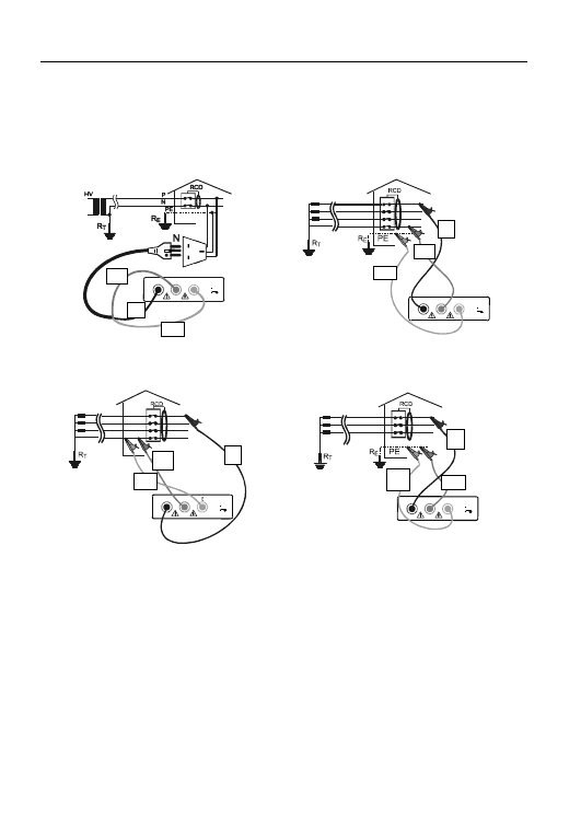
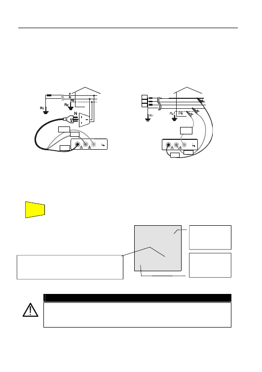
4.3.1. Procedure for RCD testing
1. Select the desired mode (MAN, x1, x2, x5, AUTO, *RAMP) with the FUNC key.
2. Connect the 3 red, black and green connectors of the three-terminal mains cable, or
the single test leads, to the corresponding input terminals of the instrument P, N, E (see
possible connections in the pictures below). If using un-terminated cables connect the
crocodile clips to the free ends of the cables.
P
E
L2
N
L3
P
L1
(P)
CAT II I
INPUT MAX
440 V P-N-E
250 V
Connection for 230V single-phase RCD check
R
S
T
N
E
L2
N
L3
P
L1
(P)
CAT III
INPUT MAX
440 V P-N-E
250 V
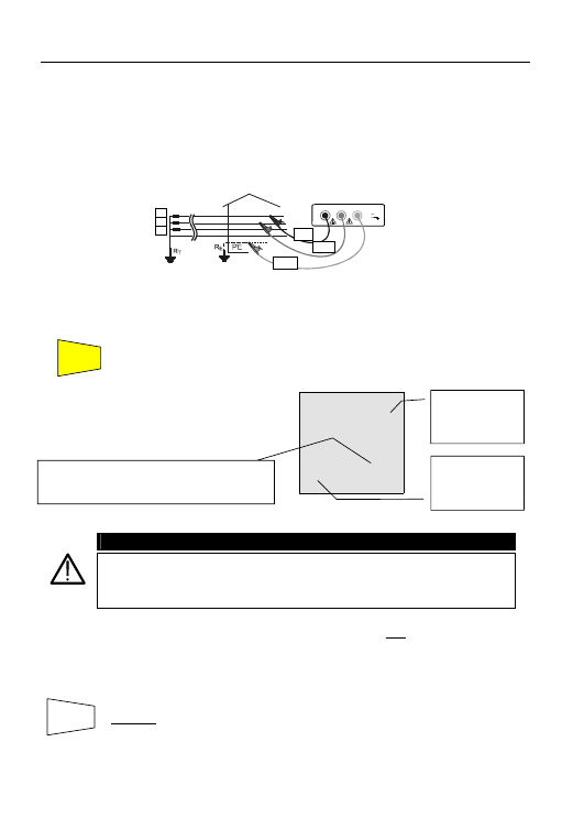
Connection for 400V + N + PE three-phase RCD
check
R
S
T
N
L2
N
L3
P
L1
(P)
CAT I II
INPUT MAX
440 V P-N-E
250 V
Connection for 400V + N (no PE) three-phase RCD
check
R
S
T
E
L2
N
L3
P
L1
(P)
CAT II I
INPUT MAX
440 V P-N-E
250 V
Connection for 400V + PE (no N) three-phase
RCD check
*VR2240 ONLY
Black
Green
Red
Green
Green
Black
Green
Black
Black
Red
Red
Red
L1
L2
L3
L1
L2
L2
L1
L3
L3
28
4.3.1.1. "MAN
x½" Mode
4.
)
Press the GO key once. The instrument carries out the test injecting a
current in phase with positive half wave of the voltage indicated on
display by 0°.
)
Press the GO key twice. The instrument carries out the test injecting a
current in phase with negative half wave of the voltage indicated on
display by 180°.
)
RCD
~
>
999
ms
OK
Ι
∆N
30
m
A
2
V
x1/2
MAN
0° U
L
=
50
V
If the RCD does NOT trip the
instrument emits a double sound
signal indicating a positive outcome
of the test and displays a screen similar
to this.
*
*The test can be stored pressing the SAVE key twice
* VR2240 only
Value of contact
voltage U
t
detected, referred
to the rated value
of the RCD
current set.
OK: indicates that
RCD passed the
test.
The symbol ">" indicates that the RCD did not trip.
Indicates that the test was carried out with current
in phase by 0° or 180° with respect to the voltage.
Limit set for the
contact voltage
or RCD
SAVE
GO
29
4.3.1.2. "MAN
x1, x2 & x5" Modes
4.
)
Press the GO key once. The instrument carries out the test injecting a
current in phase with positive half wave of the voltage indicated on
display by 0°.
)
Press the GO key twice. The instrument carries out the test injecting a
current in phase with negative half wave of the voltage indicated on
display by 180°.
Note: “Man 5x I
∆n
” and “AUTO” test modes are not available for 500mA RCD type A
.
*
SAVING:
*The test can be stored pressing the SAVE key twice
* VR2240 only
)
RCD
~
40
ms
OK
Ι
∆N
30
m
A
1
V
x1
MAN
t
0° U
L
=
50
V
When the RCD trips, and if the tripping
time is within certain limits, the
instrument emits a double sound
signal indicating the positive
outcome of the test and displays a
screen similar to this.
Value of contact
voltage U
t
detected referred
to the rated value
of the RCD
current set.
RCD tripping time
OK: The OK symbol relates only to certain trips. It
is essential to ensure that the trip is fast enough for
the trip rating and application being tested. Please
refer to the latest edition of the IEE regs for
individual tripping times.
Indicates that the test was carried out with current
in phase by 0° or 180° with respect to the voltage
Limit set for the
contact voltage.
or RCD
SAVE
GO
30
4.3.1.3. "AUTO" Mode
4. Press
the
GO key: The instrument carries out the following six
tests with different values of rated current:
)
1/2x I
∆n
at 0° (the RCD should not trip).
)
1/2x I
∆n
at 180° (the RCD should not trip).
)
I
∆n
at 0° (the RCD trips, blinking rcd, switch it on again).
)
I
∆n
at 180° (the RCD trips, blinking rcd, switch it on again).
)
5x I
∆n
at 0° (the RCD trips, blinking rcd, switch it on again).
)
5x I
∆n
at 180° (the RCD trips, end of the test).
In AUTO mode for each positive result of a single test, the
following are displayed:
OK test passed.
Blinking rcd. Switch the RCD on again (if the RCD is not switched on
again the instrument does not proceed with the test).
The test ends if all values of test tripping times fall within limits, or at the
first value out of limits.
Note: ”Man 5x I
∆n
” and “AUTO” test modes aren’t available for 500mA RCD type A
.
)
RCD
~
23
ms
OK
Ι
∆N
30
m
A
1
V
x5
t
AUTO
180° U
L
=
50V
At the end of the test if
all six results are
positive, the instrument
displays the screen
alongside with the last
measurement
performed.
5. Press
the
DISP key to scroll between the results for the six tests
performed which can be shown in rotation in the following order:
½I
∆n
at 0°, ½I
∆n
at 180°, I
∆n
at 0°, I
∆n
at 180°, 5I
∆n
at 0°, 5I
∆n
at 180°.
*
SAVING:
*The test can be stored pressing the SAVE key twice
* VR2240 only
OK: indicates that the RCD
passed the test.
DISP
Value of
contact voltage
U
t
detected.
SAVE
or RCD
GO
31
4.3.1.4. *
"RAMP " Mode (VR2240 ONLY)
4.
)
Press the GO key once. The instrument carries out the test injecting
a current in phase with positive half wave of the voltage indicated on
display by 0°.
)
Press the GO key once. The instrument carries out the test injecting a
current in phase with negative half wave of the voltage indicated on
display by 180°.
The instrument generates a leakage current growing step by step in a given time interval.
)
RCD
~
24
mA
OK
41
m
s 1 V
t
0° U
L
= 50
V
At the end of the test if the RCD tripping
current is
≤ I
∆n
(Type AC) or 1.4 I
∆n
(Type A with I
∆n
> 10mA) or 2 I
∆n
(Type
A with I
∆n
≤ 10mA), the instrument emits
a double sound signal indicating the
positive outcome of the test and
displays a screen similar to this.
*
SAVING:
*The test can be stored pressing the SAVE key twice
If the parameters set on the instrument are consistent with the RCD under test, the ramp test
“ ” WILL CAUSE RCD TRIPPING WITH A CURRENT LOWER THAN OR EQUAL TO THE
SELECTED RATED DIFFERENTIAL CURRENT. Do not use this test to compare the trip
time with the trip current, as the RCD has to be tested for tripping time with a current equal
to and over that of the rated leakage current of the RCD.
* VR2240 only
SAVE
RCD tripping time
OK: indicates that
the RCD passed
the test.
Value of contact voltage U
t
detected referred to the
rated value of the RCD current set.
or RCD
GO
32
4.3.1.5. Mode
"U
t
"
4. ) Press
the
GO key once: the instrument carries out the test.
)
RCD
~
1.4
V
OK
Ι
∆N
30
m
A
49
Ω
U
t
0° U
L
=
50
V
If the RCD does NOT trip the
instrument emits a double sound
signal indicating the positive
outcome of the test and displays a
screen similar to this.
*
SAVING:
*The tests can be stored by pressing the SAVE key twice
* VR2240 only
Value of earth resistance R
a
. is displayed. If "o.r."
is displayed, this indicates that the instrument
detected a resistance higher than 1999
Ω.
Value of contact voltage U
t
detected refers to the
rated value of the RCD current set.
this indicates that
the test was
carried out with
current in phase
(0°) or phase
shifted (180°) with
respect to the
voltage.
SAVE
OK: indicates that
the RCD passed
the test.
or RCD
GO
33
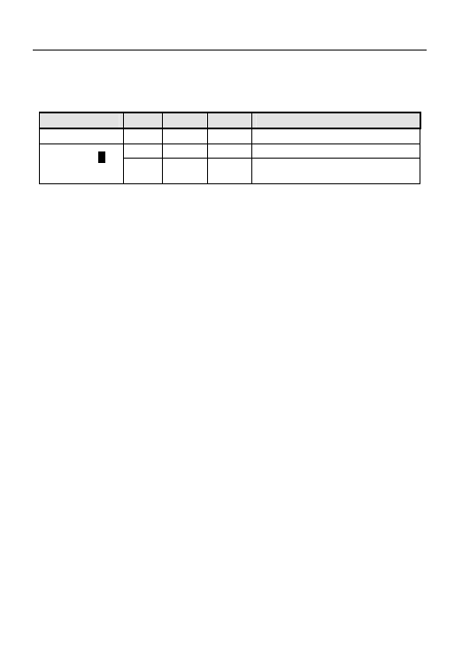
4.3.2. Tripping times for general and selective RCDs
If the parameters set on the instrument are in keeping with the type of RCD under test (and
if this works correctly) the test with leakage current I
∆N
x1, I
∆N
x2, I
∆N
x5 SHOULD cause
RCD tripping within the times set according to the following table:
RCD type
I
∆N
x 1
I
∆N
x 2
I
∆N
x 5
Description
General 0.3s
0.15s
0.04s
Max tripping time in seconds
0.5s 0.20s 0.15s
Max tripping time in seconds
Selective
S
0.13s 0.05s 0.05s Minimum delay tripping time in
seconds
For rated values I
∆N ≤ 30mA the test current at five times is 0.25A.
For currents equal to ½
I
∆N
the RCD should not trip in any case.
Tripping times for tests with leakage currents I
∆N
x1, I
∆N
x2, I
∆N
x5 and AUTO.
4.3.2.1 Note
The above values apply to RCDs manufactured to comply with BSEN61008. RCDs
which are manufactured to comply with BS4293 are required to operate in 0.2s at
I
∆
N
X1. It is important that the user of this instrument is aware of the applicable
tripping time(s) for the RCD being tested.
34
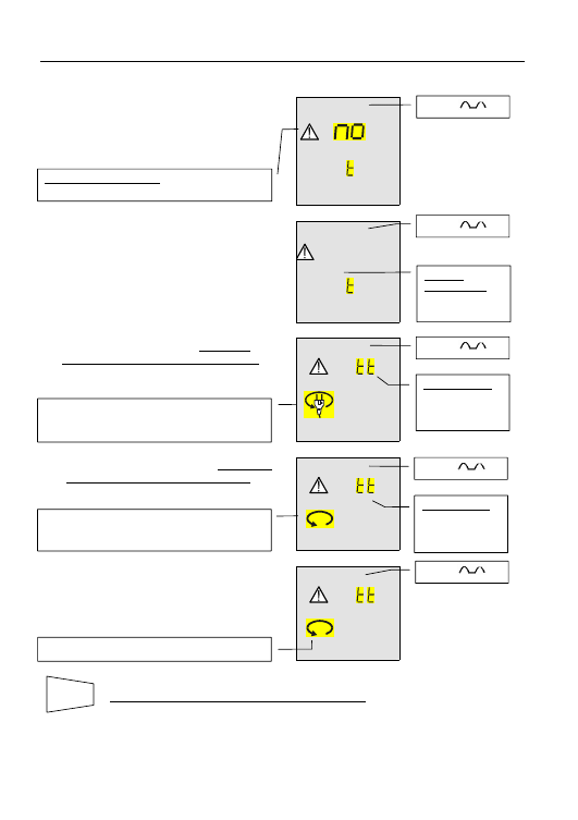
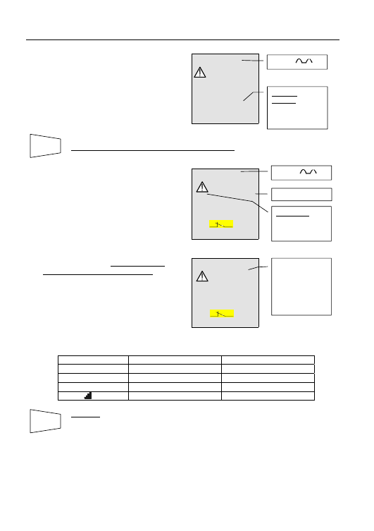
4.3.3. Other situations which may occur during RCD tests in any working mode
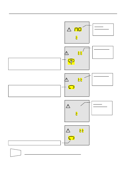
)
RCD
~
P-N
VOL AG
Should the instrument detect that the
phase and/or neutral cables are not
connected to an installation, the screen
alongside is displayed when pressing
GO.
)
RCD
~
Hi
P-N
VOL AG
Should the instrument detect a voltage
between phase and neutral higher than
265V, for Example if the black cable is
connected to an installation phase
conductor of a 400V three-phase
system, the screen alongside is
displayed.
)
RCD
~
A
P-N
This screen is displayed if the phase
conductor is reversed with the neutral.
)
RCD
~
A
P-PE
This screen is displayed if the phase
conductor is reversed with the earth.
)
RCD
~
A
PEN
This screen is displayed when in a 2
phase system the black conductor is
reversed with the green.
*
THE PREVIOUS RESULT CANNOT BE SAVED.
* VR2240 only
Message “no VOL tAGE”: too low a voltage was
detected
Message "Att":
voltage between
phase and earth
is too low.
The instrument does not perform the test.
Exchange the black cable with the red. Repeat the
test.
Message "Att":
voltage between
phase and earth
is too low.
The instrument does not perform the test.
Reverse the phase to earth connection in the plug
or exchange the red cable with the green.
Message
“Hi VOL tAG”:
too high a voltage
was detected.
The instrument does not perform the test.
or RCD
or RCD
or RCD
SAVE
or RCD
or RCD
35
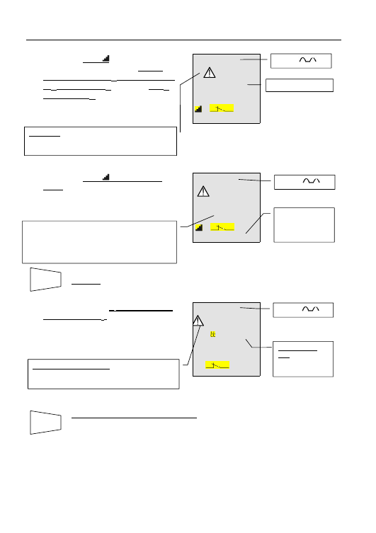
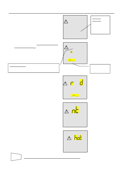
)
RCD
~
>
1999
Ω
no
PE
If the instrument detects that the earth
cable (green) is not connected, the
screen alongside is displayed for 5
seconds after which time the screen
reverts to the initial display. Check the
connections of PE conductor under
test.
*
THE PREVIOUS RESULT CANNOT BE SAVED.
)
RCD
~
487
ms
Ι
∆N
30
m
A
1
V
x
1
MAN
t
0°
U
L
=
50
V
During the tests MAN x1, x2, x5 and
AUTO (during x1 and x5 tests), if the
RCD trips to break the circuit within a
time not complying with the limits in
table 4.3.2, the instrument emits a long
sound signal at the end of the test and
displays the values alongside.
*Refer also to note 4.3.2.1
)
RCD
~
>
999
mS
Ι
∆N
30
m
A
2
V
x
1
MAN
t
0° U
L
=
50 V
If the RCD trips in a time higher than
the instrument’s measuring limits, the
instrument emits a long sound signal
at the end of the test and displays the
values alongside.
The maximum duration depends on the test type:
Test type
General RCD
Selective RCD
MAN x1 test
999ms
999ms
MAN x2 test
200ms
250ms
MAN x5 test
50ms
160ms
*“ ” test
300ms
*
SAVING:
*The tests can be stored by pressing the SAVE key twice
* VR2240 only
RCD tripping time
WARNING: the
tripping time is
higher than the
standard limit.
RCD tripping
time:
> maximum
measuring time
(depending on
type of test, see
table below).
Message
“no PE”: the
instrument does
not detect the
protection circuit.
SAVE
or RCD
or RCD
SAVE
36
)
RCD
~
>
300
mS
Ι
∆N
42
m
A
2
V
t
0°
U
L
=
50 V
*During the ramp test for general
RCDs if the RCD trips to break the
circuit, the instrument emits a long
sound signal at the end of the test and
displays a screen similar to this.
*
SAVING:
*The tests can be stored by pressing the SAVE key twice
)
RCD
~
>
50
V
A
UL
I
∆N
x5
MAN
t
0° U
L
=50V
If a contact voltage U
t
higher than the
selected limit (U
L
) is detected the
instrument stops the test, emits a long
sound signal and displays a screen
similar to this.
*
THIS RESULT CANNOT BE SAVED.
In order to store the contact voltage value U
t
, perform the test under U
t
mode.
* VR2240 only
)
RCD
~
33
mA
58
m
s
1
V
t
0°
U
L
=
50
V
*During the ramp test, if the RCD
trips to break the circuit at a tripping
current higher than I
∆n
(Type AC) or 1.4
x I
∆n
(Type A with I
∆n
>10mA) or 2 x I
∆n
(Type A with I
∆n
≤10mA), the instrument
emits a long sound signal at the end
of the test and displays a screen similar
to this.
Message "Att
UL": too higher
contact voltage
was detected.
WARNING: the RCD tripping current is higher than
the rated value of the set differential current
(I
∆N
=30mA was set in the Example
).
Maximum current generated by the instrument
during the test for general RCDs (the value
indicated refers to an AC type 30mA RCD, in this
case the maximum current supplied is equal to
1.4xI
∆N
)
Contact voltage
U
L
refers to the
value of rated
current.
SAVE
RCD tripping current
or RCD
or RCD
SAVE
or RCD
Message “>50V” o “>25V”: the instrument
detects a contact voltage higher than the selected
limit (50V in this case).
37
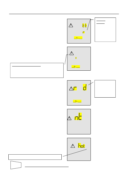
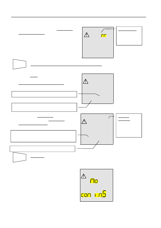
)
RCD
~
A
Ι
∆N
hi
ES
t
AUTO
0° U
L
=
50 V
If the instrument is unable to generate
the current because the fault loop
presents a too high a resistance, the
instrument emits a long sound signal
at the end of the test and displays a
screen similar to this
)
RCD
~
>
100
V
A
UL
I
∆N
t
0° U
L
=50V
During the U
t
test if the instrument
detects a contact voltage U
t
higher than
the full scale value, a long sound signal
is emitted at the end of the test and
displays a screen similar to this.
)
RCD
~
c
Ι
∆N
- - - - - -
x
1
MAN
t
0° U
L
=
50V
If the RCD trips during the preliminary
test at ½ I
dn
(independently from the
working mode) the instrument displays
the screen alongside until voltage
between phase and earth is detected
(RCD reset) after which time the screen
reverts to the initial display
)
RCD
~
c
If the thermistors of the instrument are
damaged, a screen similar to this is
displayed.
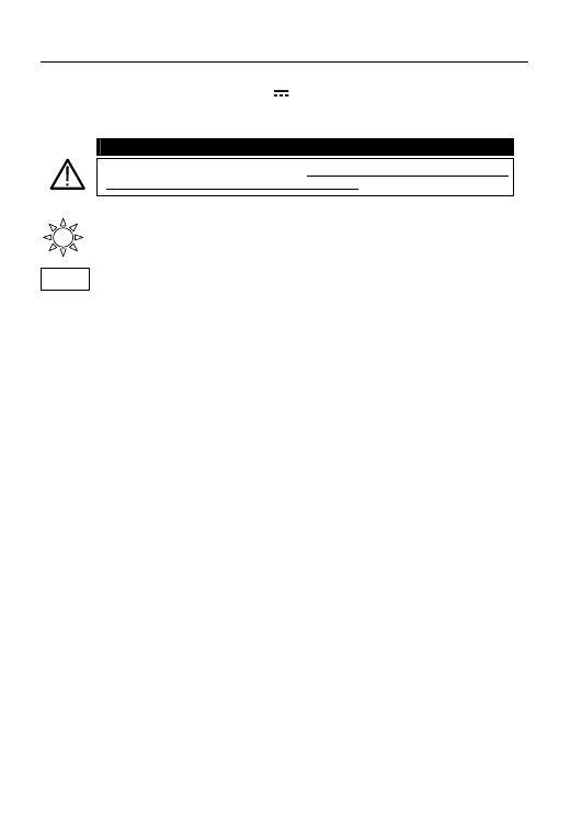
)
RCD
~
If the instrument becomes overheated,
tests cannot be carried out and the
message alongside is displayed. Wait
until the screen reverts to the initial
display in order to proceed.
*
THIS RESULT CANNOT BE SAVED.
* VR2240 only
Message ">100V" or “>50V”:
the instrument detected a contact voltage higher
than the full scale. Under U
t
mode the instrument
full scale is equal to 100V or 50V depending on the
value set for U
L
equal to 50V or 25V.
Message “rcd”:
the RCD trips too
early. Some
leakage currents
may be present in
the installation.
Message “hot”: the instrument overheated.
Message
“HI rES”: the
instrument
detected a
excessive
resistance
therefore it is
unable to perform
the test.
SAVE
38
4.4. LOOP
Z
S
/I
K
:
MEASUREMENT OF LINE IMPEDANCE, FAULT LOOP
IMPEDANCE AND CALCULATION OF PROSPECTIVE
SHORT CIRCUIT AND FAULT CURRENT
WARNING
This test is designed for use where there is no RCD in the circuit.
This test will trip the RCDs.
Turn the switch to LOOP Z
S
/I
K
position.
The FUNC key is used to select one of the following measuring modes (which
can be shown in rotation when pressing the key):
)
“P-N” Mode (the instrument measures the resistance between the phase
and neutral conductors and calculates the phase to neutral prospective
short circuit current).
)
“P-P” Mode (the instrument measures the resistance between two phase
conductors and calculates the phase to phase prospective short circuit
current).
)
“P-PE” Mode (the instrument measures the resistance between the phase
and protective conductors and calculates the phase to earth prospective
fault current).
WARNING
When “Measuring” is indicated on the display, the instrument is carrying out
a test. Never disconnect test leads while “Measuring” is displayed.
FUNC
39
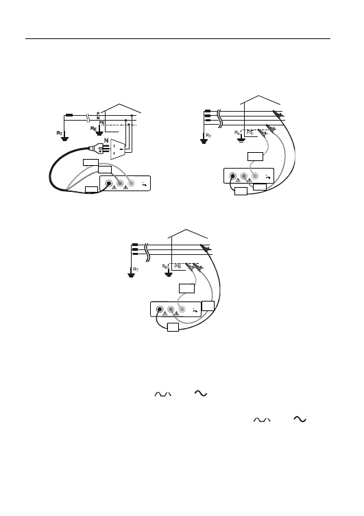
4.4.1. "P-N" Mode
1. Select P-N mode with the FUNC key.
2. If possible disconnect all low impedance loads downstream of the point at which the
measurement is to be taken, since such impedances would be in parallel with the line
impedance to be measured.
3. Connect the red, black and green connectors of the mains lead (13a plugtop) or of the singular
test leads to the corresponding input terminals of the instrument. (see diagrams below). When
testing disconnected cables, connect the crocodile clips to the free ends of these.
P
E
L2
N
L3
P
L1
(P)
CAT III
INPUT MAX
440 V P-N-E
250 V
Instrument connection for 230V single-phase or
two-phase line impedance measurement
R
S
T
N
E
L2
N
L3
P
L1
(P)
CAT II I
INPUT MAX
440 V P-N-E
250 V
Instrument connection for line impedance
measurement in a 400V three-phase system
4. Put the mains plug into a 230V 50Hz socket or connect the crocodile clips to the
conductors of the three-phase system (see pictures).
5. Press
the
GO key. The instrument starts the test.
)
LOOP
1.07
Ω
P-N
223
V
214
A
At the end of the test the instrument
emits a double sound signal
indicating that the test completed
correctly and displays a screen similar
to this.
WARNING
The measurement of Phase-Neutral impedance entails the flow of a current
of about 6A between the two conductors. This may cause the tripping of
magnetothermal RCDs with nominal value lower than 10A. If necessary
perform the test upstream of the RCD itself.
Value of phase to
neutral line
impedance
expressed in
Ω.
Phase to neutral
effective voltage
value expressed
in Volts.
Effective value of the phase to neutral prospective
short circuit current expressed in Ampere
calculated according to the formula on the next
page.
GO
Black
Green
Red
Red
Black
Green
L1
L2
L3

40
Calculation formula for prospective short circuit current:
PN
N
CC
Z
U
I
=
where U
N
= phase to neutral voltage 127V if V
meas
≤ 150V
230V if 150V < V
meas
≤ 265V
*
SAVING:
*The tests can be stored by pressing the SAVE key twice
* VR2240 only
SAVE
41
4.4.2. "P-P" Mode
1. Select P-P mode with the FUNC key.
2. If possible disconnect all low impedance loads downstream of the point at which the
measurement is to be taken, since such an impedance would be in parallel with the line
impedance to be measured.
3. Connect the three red, black and green connectors of the test leads to the corresponding
input terminals of the instrument P, N, E (see possible connections in the following
pictures).
R
S
T
N
E
L2
N
L3
P
L1
(P)
CAT II I
INPUT MAX
440 V P-N-E
250 V
Connections for measurement of phase to phase impedance
4. Connect the crocodile clips to the conductors of the three-phase system (see picture).
5. Press
the
GO key. The instrument starts the test.
)
LOOP
1.07
Ω
P-P
383
V
374
A
At the end of the test the instrument
emits a double sound signal
indicating that the test completed
correctly and displays a screen similar
to this.
WARNING
The measurement of Phase-Phase impedance entails the flow of a current of
about 11.5A between the two conductors. This may cause the tripping of
magnetothermal RCDs with nominal value lower than 10A. If necessary
perform the test upstream of the RCD itself.
Formula for calculation of prospective short circuit current:
PP
N
CC
Z
U
I
=
where
U
N
= phase to phase voltage 127V if V
meas
≤ 150V
230V if 150V < V
meas
≤ 265V
400V if V
meas
> 265V
*
SAVING:
*The tests can be stored by pressing the SAVE key twice
* VR2240 only
Value of phase to
phase line
impedance
expressed in
Ω.
Phase to phase
effective voltage
value expressed
in Volts.
Effective value of the phase to phase prospective
short circuit current expressed in Amperes
calculated according to the formula below.
SAVE
GO
Black
Green
Red
L1
L2
L3
42
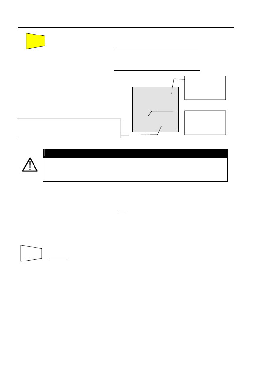
4.4.3. Mode "P-PE"
1. Select P-PE mode with the FUNC key.
2. Connect the three red, black and green connectors of the three-terminal mains test lead or of
the single test leads in the corresponding input terminals of the instrument P, N, E (see
possible connections in the following pictures).
P
E
L2
N
L3
P
L1
(P)
CAT III
INPUT MAX
440 V P-N-E
250 V
Connections for loop impedance measurement in
a 230V single- or two-phase system
R
S
T
N
E
L2
N
L3
P
L1
(P)
CAT III
INPUT MAX
440 V P-N-E
250 V
Connections for loop impedance measurement in
a 400V three-phase system with neutral
R
S
T
E
L2
N
L3
P
L1
(P)
CAT II I
INPUT MAX
440 V P-N-E
250 V
Measurement of loop impedance in a 230 or 400V three-phase system without neutral
3. Connect the mains plug into a 230V 50Hz socket or the crocodile clips to the conductors
of the three-phase system (see pictures).
4. The instrument carries out the test verifying that the contact voltage of the installation is
not higher than the limit contact voltage value. The contact voltage limit is that set under
one of the following functions: RCD
, RCD
or R
a15mA
.
Example: if you are carrying out tests in an area where the limit contact voltage is equal
to 25V, you will need to select one of the following functions: RCD
, RCD
or
Ra
15mA
, and select the limit contact voltage of 25V using U
L
▼. At this stage if you turn the
selector on LOOP Z
S
/I
K
under mode P-PE, the instrument will use the limit of 25V during
the test.
Black
Red
Green
Black
Black
Red
Red
Green
Green
L1
L2
L3
L1
L2
L3
43
5.
)
Press the GO key once. The instrument carries out the test injecting
a current in phase with positive half wave of the voltage indicated on
display by 0°.
)
Press the GO key twice. The instrument carries out the test injecting
a current in phase with negative half wave of the voltage indicated on
display by 180°.
)
LOOP
3.65
Ω
P-PE
221
V
63
A
At the end of the test the instrument
emits a double sound signal
indicating that the test completed
correctly and displays a screen similar
to this.
WARNING
The measurement of Phase-PE impedance entails the flow of a current of
about 11.5A between the two conductors. This may cause the tripping of
magnetothermal RCDs with nominal value lower than 10A. If necessary
perform the test upstream the RCD itself.
Formula for calculation of prospective fault current:
PE
N
CC
Z
U
I
=
where U
N
= phase to earth voltage
127V if 100V < V
meas
< 150V
230V if 150V < V
meas
≤ 265V
*
SAVING:
*The tests can be stored by pressing the SAVE key twice
* VR2240 only
Value of phase to
earth fault
impedance
expressed in
Ω.
Phase to earth
effective voltage
value expressed
in Volts.
Effective value of the phase to earth prospective
short circuit current expressed in Ampere
calculated according to the formula below.
SAVE
GO
44
4.4.4. Other situations which may occur during LOOP, Z
S
/I
K
tests in any working mode
)
LOOP
P-N
VOL AG
Should the instrument detect that the
phase and/or neutral cables are not
connected to an installation, the screen
alongside is displayed when pressing
GO.
)
LOOP
A
P-N
This screen is displayed if the phase
conductor is reversed with the neutral.
)
LOOP
A
P-PE
This screen is displayed if the phase
conductor is reversed with the earth.
)
LOOP
Hi
P-N
VOL AG
Should the instrument detect a voltage
between phase and neutral higher than
265V, for Example if the black cable is
connected to an installation phase
conductor of a 400V three-phase
system, a screen similar to this is
displayed.
)
LOOP
A
PEN
This screen is displayed if when testing
a 2 phase system, the black conductor
is reversed with the green.
*
THE PREVIOUS RESULT CANNOT BE SAVED.
* VR2240 only
Message
"no VOL tAG”:
too low a voltage
was detected.
The instrument does not perform the test.
Exchange the red test lead with the black. Check
the earth connection. Repeat the test.
The instrument does not perform the test.
Reverse the phase to earth connection under test
or exchange the red test lead with the green.
Repeat the test.
The instrument does not perform the test.
Message “Att”:
too low a voltage
between phase
and earth.
Message “Att”:
too low a voltage
between phase
and neutral.
Message
“Hi VOL tAG”: a
too high a voltage
was detected.
SAVE
45
)
LOOP
>
1999
Ω
no
PE
If the instrument detects that the earth
cable (green) is not connected, the
screen alongside is displayed for 5
seconds then the screen reverts to the
initial display. Check the connections of
PE conductor under test.
)
LOOP
>
50
V
A
UL
t
0° U
L
=50V
If a contact voltage U
t
higher than the
selected limit (U
L
) is detected the
instrument stops the test and emits a
long sound signal at the end of the
test. A screen similar to this is
displayed.
)
LOOP
c
P-P
--- ---
t
If during the test the instrument does
not detect voltage, a screen similar to
this is displayed.
)
LOOP
c
If the thermistors of the instrument are
damaged, a screen similar to this is
displayed.
)
LOOP
*
If the instrument becomes overheated,
tests cannot be carried out and the
message alongside is displayed. Wait
until the screen reverts to the initial
display in order to proceed.
*THE PREVIOUS RESULT CANNOT BE SAVED
* VR2240 only
">50" or “>25V”: the instrument detects a contact
voltage higher than the selected limit (50V in this
case).
The instrument
displays 0° or
180°
SAVE
Message
“no PE”: the
instrument does
not detect the
protection
circuit.
46
)
LOOP
e
P-P
if the instrument detects a resistance
lower than 0,03
Ω, the screen alongside
is displayed. Line impedance value is
too low and the instrument doesn’t
perform the measurement
*
THE PREVIOUS RESULT CANNOT BE SAVED.
)
LOOP
>
1999
Ω
218
V
0
A
If using P-PE mode the instrument
carries out the test and detects a
resistance higher than 1999
Ω, a
screen similar to this displayed.
)
LOOP
>
199.9
Ω
P-N
218
V
0
A
Under mode P-P or P-N if the
instrument detects a resistance
higher than 199.9
Ω a screen similar to
this displayed.
* SAVING:
*The tests can be stored by pressing the SAVE key twice
)
LOW
Ω
LOOP
*This screen can be inadvertently
displayed if the U
n
/I
∆n
button is pressed
when in the LOOP Z
S
/I
K
range. This is
a function reserved for future use. To
return the display back to the default
screen, press the U
n
/I
∆n
button again.
Note: Unless the U
n
/I
∆n
is pressed to return the screen to
default, the “no con ins” screen will remain active in the
LOOP Z
S
/I
K
range even if the unit is powered down or if the
batteries are removed.
* VR2240 only
Message
">199.9":
the instrument
detects a line
loop resistance
higher than
199.9
Ω.
Value of voltage existing between the phase to
phase (if the test is P-P), phase to neutral (if the
test is P-N).
Generated current. Resolution 1A.
Value of voltage existing between the phase &
earth terminals on the instrument. (P-PE)
Generated current. Resolution 1A.
SAVE
Message "Err":
the instrument
detects a line
loop resistance
lower than 0.03
Ω.
SAVE
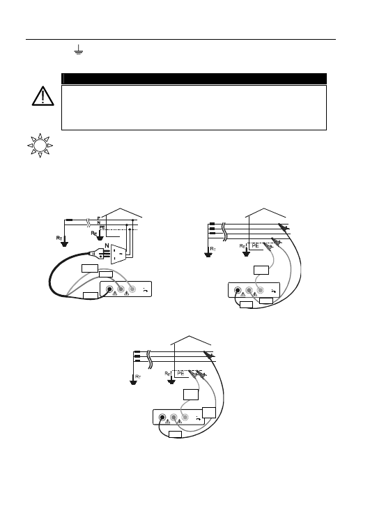
47
4.5. R
a15mA
: MEASUREMENT OF EARTH RESISTANCE WITH 15mA CURRENT
AND CALCULATION OF PROSPECTIVE FAULT CURRENT (PFC)
WARNING
This test is designed for circuits where there is an RCD. Provided pre-existing
levels of earth leakage are low this test will not trip RCDs. The test results are
presented to 1
Ω resolution. Where an RCD is available for extra protection,
there is no need to specify the loop to 2 decimal places. Records stated for
example as “
≤1Ω” are acceptable.
Turn the switch to R
a15mA
position.
)
The only available mode is P-PE.
1. Connect the three red, black and green connectors of the three-terminal mains test lead
or of the single test leads to the corresponding input terminals of the instrument P, N, E
(see possible connections in the following pictures). When testing at loose cables,
connect the crocodile clips to the free ends of these
P
E
L2
N
L3
P
L1
(P)
CAT III
INPUT MAX
440 V P-N-E
250 V
Connection for Earth Resistance in a 230V single-
or two-phase system
R
S
T
N
E
L2
N
L3
P
L1
(P)
CAT II I
INPUT MAX
440 V P-N-E
250 V
Connection for Earth Resistance in a 400V three-
phase system with neutral
R
S
T
E
L2
N
L3
P
L1
(P)
CAT II I
INPUT MAX
440 V P-N-E
250 V
Earth Resistance in a 230V or 400V three-phase system without neutral
2. Connect the mains plug into a 230V 50Hz socket or the crocodile clips
to the conductors of the three-phase system (see picture).
Black
Black
L1
Green
Red
Green
Green
Red
Red
Black
L2
L3
L1
L2
L3
48
3. The
U
L
▼ key is used to select one of the following limit values for
the contact voltage (which can be shown in rotation when pressing the key):
)
50V (default)
)
25V.
4. Press
the
GO key. The instrument starts the test.
)
RCD LOOP
49
Ω
P-PE
3
V
4
A
At the end of the test the instrument
emits a double sound signal indicating
that the test completed correctly and
displays a screen similar to this
Note: The test is used to perform the measurement of Earth Resistance without causing
the RCD to trip. (RCD rated I
∆N
higher than or equal to 0.03A.)
Formula for the calculation of the prospective short circuit current:
A
N
CC
R
U
I
=
where U
N
= phase to earth voltage
127V if 100V < V
meas
≤ 150V
230V if 150V < V
meas
≤ 265V
R
A
= earth resistance
WARNING
When “Measuring” is indicated on the display, the instrument is carrying out
a test. Never disconnect test leads while “Measuring” is displayed.
*
SAVING:
*The tests can be stored by pressing the SAVE key twice
* VR2240 only
Value of Earth
Resistance
expressed in
Ω.
Resolution
is 1
Ω.
Value of contact
voltage detected
during the
measurement
with leakage
current of 15mA.
Resolution is 1V.
Effective value of the phase to earth prospective
fault current (PFC) expressed in Amperes
calculated according to the formula below.
Resolution is 1A.
U
L
▼
SAVE
GO
Signifies non- trip
low current loop
test
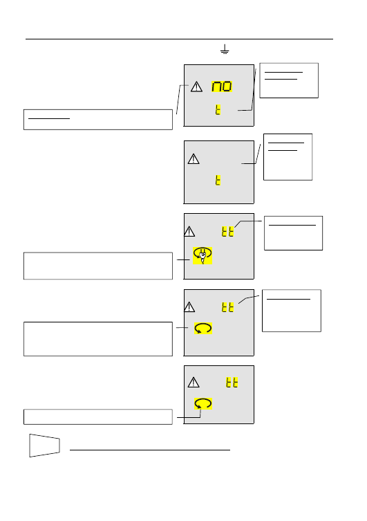
49
4.5.1. Other situations which may occur during R
A15mA
tests
)
RCD LOOP
P-N
VOL AG
Should the instrument detect that the
phase and/or neutral cables are not
connected to an installation, a screen
similar to this is displayed when
pressing GO.
)
RCD LOOP
Hi
P-N
VOL AG
Should the instrument detect a voltage
between phase and neutral higher than
265V, for Example if the black cable is
connected to an installation phase
conductor of a 400V three-phase
system, a screen similar to this is
displayed.
)
RCD LOOP
A
P-N
This screen is displayed if the phase
conductor was reversed with respect to
the neutral.
)
RCD LOOP
A
P-PE
This screen is displayed if the phase
conductor is reversed with the earth.
)
RCD LOOP
A
PEN
This screen is displayed if when testing
a 2 phase system, the black conductor
is reversed with the green.
*
THE PREVIOUS RESULT CANNOT BE SAVED.
* VR2240 only
Message "no": the instrument does not perform
the test because too low a voltage was detected.
Message “No
VOLTAGE”:
Too low a voltage
was detected.
Message "ATT":
voltage between
phase and earth
is too low.
The instrument does not perform the test.
Exchange the red test lead with the black. Check
the earth connection. Repeat the test.
Message “Hi
VOL tAG”:
Too high a
voltage was
detected
The instrument does not perform the test
SAVE
Message "Att":
voltage between
phase and
neutral is too
low.
The instrument does not perform the test.
Reverse the phase to earth connection under test
or exchange the red test lead with the green.
Repeat the test.
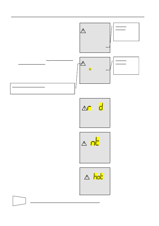
50
)
RCD LOOP
>
1999
Ω
no
PE
If the instrument detects that the earth
cable (green) is not connected, the
screen alongside is displayed for 5
seconds then the screen reverts to the
initial display. Check the connections of
PE conductor under test.
)
RCD LOOP
>
50
V
A
UL
If a contact voltage U
t
higher than the
selected limit (U
L
) is detected the
instrument stops the test and emits a
long sound signal at the end of the
test. A screen similar to this is
displayed.
)
RCD
LOOP
c
--- ---
If during the test the instrument does
not detect voltage, a screen similar to
this is displayed.
)
RCD
LOOP
c
If the thermistors of the instrument are
damaged, a screen similar to this is
displayed.
)
RCD
LOOP
If the instrument becomes overheated,
tests cannot be carried out and the
message alongside is displayed. Wait
until the screen reverts to the initial
display in order to proceed.
*
THE PREVIOUS RESULT CANNOT BE SAVED
* VR2240 only
Message
"no PE": the
instrument does
not detect the
protection circuit.
SAVE
Message
"Att UL": Too
high a contact
voltage was
detected
Message ">50" or “>25V”:
The instrument detects a contact voltage higher
than the selected limit (50V in this case)
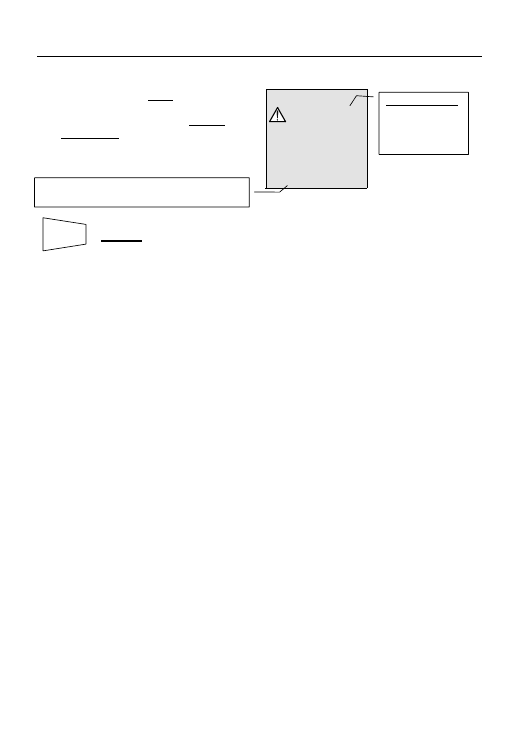
51
)
RCD LOOP
>
1999
Ω
P-PE
31
V
0
A
If, when using the P-PE mode the
instrument caries out the test and
detects an earth resistance higher
than 1999
Ω, a screen similar to this is
displayed for 5 seconds after which
time the screen reverts to the initial
display.
*
SAVING:
*The tests can be stored by pressing the SAVE key twice
* VR2240 only
Message ">1999":
The instrument
detects an earth
resistance higher
than 1999
Ω.
Value of contact voltage U
t
detected refers to the
value of the RCD current set. Resolution 1V.
SAVE
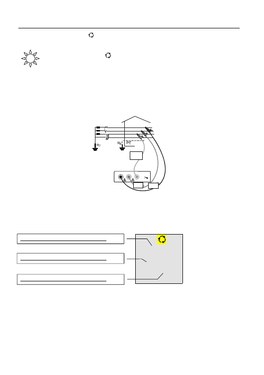
52
4.6. PHASE
SEQUENCE
Turn the switch to the
position.
4.6.1. Procedure for PHASE SEQUENCE testing
1. Connect the three red, black and green connectors of the single test leads to the corresponding
input terminals of the instrument P, N, E (see possible connections in the following picture).
When testing at loose cables or busbars, connect the crocodile clips to the free ends of these.
Caution.
High voltage may exist between phase conductors
R
S
T
N
E
L2
N
L3
P
L1
(P)
CAT II I
INPUT MAX
440 V P-N-E
250 V
Connections for phase sequence indication
L1=red cable, L2=black cable, L3=green cable
2. Connect the crocodile clips to the three phases of the system under test.
The instrument displays the following screen:
386
V
388
V
388
V
Voltage value between Phase1 and Phase2
Voltage value between Phase3 and Phase1
Voltage value between Phase2 and Phase3
Black
Green
Red
L1
L2
L3
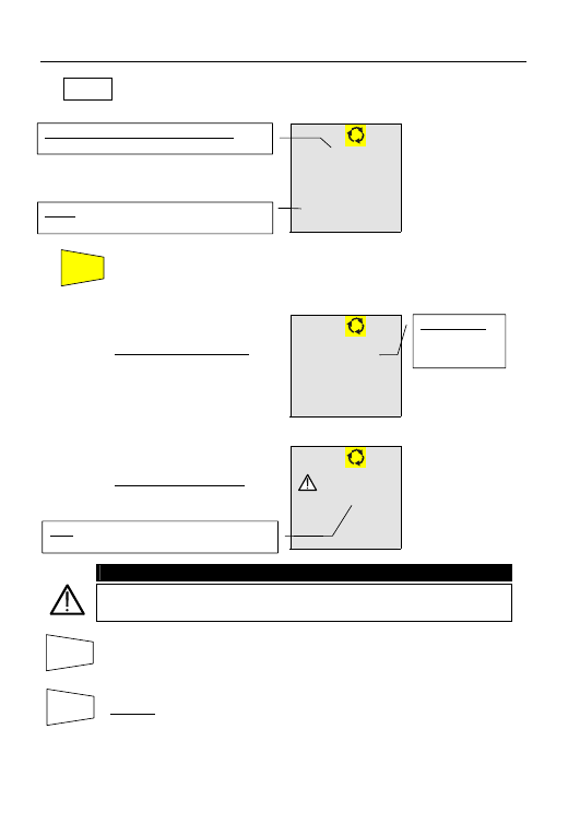
53
3.
Press the FUNC key to display the three delta voltages L1-2, L2-3, L3-1 in
turn. The instrument will display a screen similar to this:
386
V
L12
4. Press
the
GO key to start the phase sequence test. At the end of the test,
screens similar to the following will be displayed:
)
123
At the end of the test the instrument
displays a screen similar to this
indicating correct phase sequence.
I.E. the red lead is connected to the
phase1=L1, the black lead to the
phase2=L2 and green lead to the
phase3=L3.
)
213
At the end of the test the instrument
displays a screen similar to this
indicating wrong phase sequence.
WARNING
When “Measuring” is indicated on the display, the instrument is carrying out
a test. Never disconnect test leads while “Measuring” is displayed.
*
*Press the ESC key again to display the 3 voltage values L12, L23, L31 existing
between the phases of the electrical system (see the screen on page.52).
*
SAVING:
*The tests can be stored by pressing the SAVE key twice
* VR2240 only
Message "123":
indicates that the
phase sequence
is correct.
FUNC
"213": indicates that the phase sequence is wrong.
Voltage value between Phase1 and Phase2
sampled when the FUNC key is pressed.
"L12": indicates that the value reported is the
voltage measured between Phase1 and Phase2.
ESC
SAVE
GO
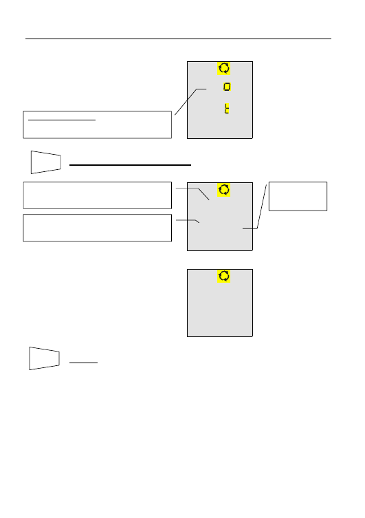
54
4.6.2. Other situations which may occur during phase sequence tests
)
L
VOL AG
if the voltage between each phase is
lower than 100V, the instrument does
not perform the test and displays a
screen similar to this.
*
THIS RESULT CANNOT BE SAVED.
0
V
0
V
388
V
)
0
V
0
V
0
V
If two or more cables of the instrument
are not connected, a screen similar to
this is displayed.
*
SAVING:
*The tests can be stored by pressing the SAVE key twice
* VR2240 only
Message “Lo VOL tAG”: the instrument detects
low voltage between at least 2 phases. The
instrument does not perform the test.
SAVE
Red cable=L1 is not connected to one phase of the
installation. No voltage between phase L1 and
phase L2 (L1-L2).
Red cable= L1 is not connected to one phase of
the installation. No voltage between phase L3 and
phase L1 (L3- L1).
Voltage between
phase L2 and
phase L3
SAVE
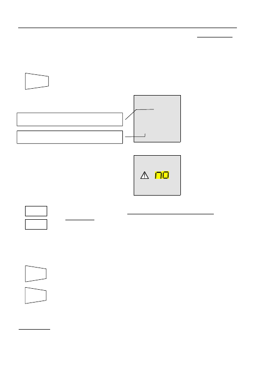
55
5. *HOW TO SAVE, RECALL AND CLEAR DATA STORED IN MEMORY (VR2240 ONLY)
5.1.
SAVE: "SAVE" KEY
To store the result of any test carried out, proceed as follows:
1. Press
the
SAVE key once.
)
LOOP
3
P02
If the memory of the instrument
contains previously stored test results,
a screen similar to this is displayed.
)
LOOP
MEM
If the test cannot be saved the
instrument displays a screen similar to
this.
2. Use
the
keys
U
L
▼, S▲ to increase or decrease the value of the
parameter P related to the measurement to be saved. This parameter
helps the operator to identify the tests performed.
Example:
if carrying out tests in different rooms within a building, the
operator can associate the measurements performed in a
room with a given value of the parameter P. Different values
of the parameter P will correspond to different rooms.
3. Press
the
SAVE key again, the instrument emits two sound signals
confirming that the test results have been stored.
Press the ESC key to leave the memory menu and go back to the
selected measurement.
VR2240 only
SAVE
U
L
▼
S▲
SAVE
The memory location in which the measurement
results will be stored.
Value of the parameter P related to the
measurement saved.
ESC
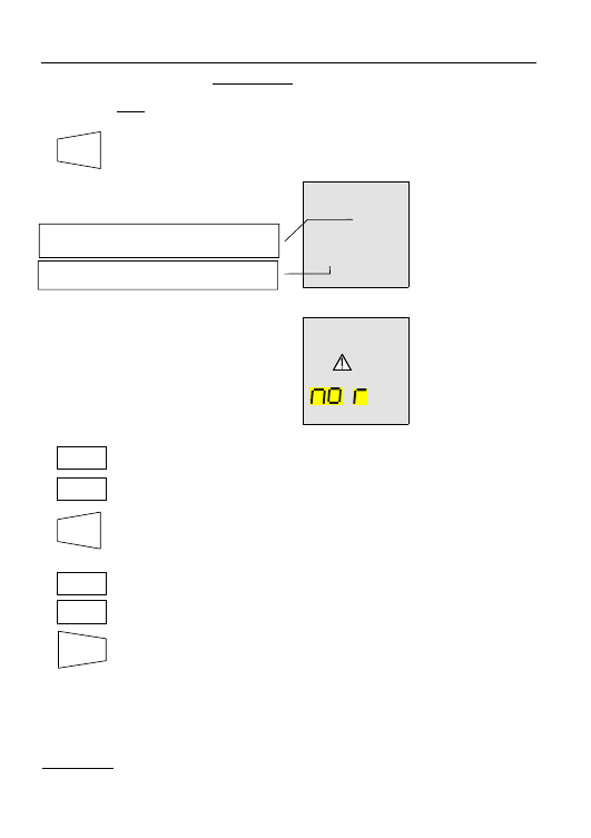
56
5.2.
*RECALL: "RCL" KEY (VR2240 ONLY)
If you want to recall the stored test results proceed as follows:
1. Press
the
RCL key.
)
MEM
3
P02
If the memory of the instrument
contains previously stored test results,
a screen similar to this is displayed.
)
LOOP
C
l
If memory of the instrument does not
contain any test results, a screen
similar to this is displayed.
2. Use
the
keys
U
L
▼, S▲ to select the memory location to be displayed.
3. Press
the
DISP key to display the test result stored within the selected
memory location.
4. Use
the
keys
U
L
▼, S▲ again to return to the memory locations.
Press the ESC key to leave the memory menu and return to the
standby screen.
VR2240 only
RCL
S▲
DISP
U
L
▼
S▲
U
L
▼
ESC
The memory location in which the measurement
result was stored to.
Value of the parameter P related to the
measurement saved.
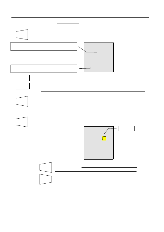
57
5.3.
*CLEAR: "CLR" KEY (VR2240 ONLY)
If you want to delete the stored tests results, proceed as follows:
1. Press
the
RCL key. The instrument displays a screen similar to this:
MEM
3
P02
2.
Use the keys U
L
▼, S▲ to select the number of the memory location.
WARNING: the instrument will delete the results stored from the
memory location selected to the last full one.
3. Press
the
DISP key to display the test result related to the memory
location selected. If more than one result is stored in the memory
location (Eg: RCD test under AUTO mode) it is necessary to press
DISP more than once to display them.
4.
Press CLR once. The symbol "
clr"
is blinks. You now have two options:
MEM
C
l
08
Press CLR again. The results selected will be deleted
starting from the one selected to the last one saved.
Press ESC to cancel deletion. The blinking symbol "clr"
disappears.
VR2240 only
RCL
U
L
▼
S▲
The memory location in which the measurement
results are stored in.
Value of the parameter P related to the
measurement saved.
DISP
CLR
CLR
ESC
Blinking.

58
Press the ESC key to leave the memory menu and go back to the
selected measurement.
Example:
97 tests have been stored in the instrument.
If you want to delete the tests from 43 to 97, proceed as follows:
- Press
RCL.
- Use the keys U
L
▼, S▲ to select the 43
rd
memory location.
- Press CLR. “CLR” will blink on the display, 43 is displayed on the left and 97
on the right.
- Press CLR. The tests from 43 to 97 are deleted.
VR2240 only
ESC
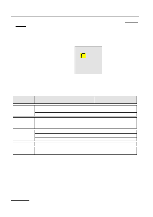
59
6. *RESETTING THE INSTRUMENT AND DEFAULT PARAMETERS (VR2240
ONLY)
6.1. RESET
PROCEDURE
1. Press the keys DISP, CLR, RCL at the same time and and turn the rotary switch to any
test function.
2.
es
The screen shown here is
displayed for approximately 5
seconds, during which the
instrument emits a sound signal
and then displays the screen relative
to the function selected with the
rotary switch.
3. WARNING:
the reset procedure will delete all the stored tests and it will set the
default parameters in the instrument.
Before carrying out a reset procedure, download the stored tests.
6.2. DEFAULT
PARAMETERS.
Function
Parameter
RESET default parameter
Mode AUTO
Calibration Offset
0
LOW
Ω
Mode R+/R- TIMER
TIMER is set at 3s
Mode MAN
Test voltage
500V
R
ISO
Mode TIMER
TIMER is set at 60s
Mode x1
Test differential current
30mA
RCD type
A/AC
Contact voltage limit
50V
LOOP Z
S
/I
K
Mode P-N
Parameter P
P = 1
Memory
Memory state
0
VR2240 only
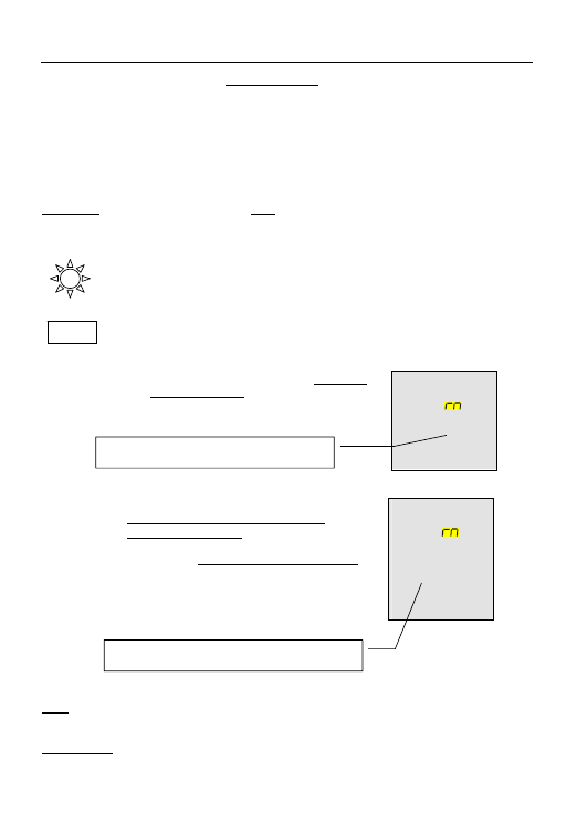
60
7. *CONNECTION TO A PC (VR2240 ONLY)
The connection from the VR2240 to a PC is made using the optional infra red data lead
VRTL1 connected to the PC serial port. The optional software package VRSOFT1 provides
the facility to download and print results onto a form (All items sold separately).
Before connecting the VR2240 to a PC, it is necessary to select and configure the COM port
on the PC used for data transfer. To set this, start the software and refer to the help provided
with the VRSOFT1 download application.
WARNING:
The selected port should NOT be shared by other devices or applications (eg.
mouse, modem, etc.).
To transfer the stored data from the VR2240 to the PC, follow the directions below.
1. Turn the rotary switch to the RS232 position (In the case of the VR2230, this
position is marked “CAL” and is only used at the point of manufacture and is
of no use to the end user of the instrument.)
2. Using the FUNC key, select the modes "Prn ALL" or "Prn n1 n2", to
display the following screens respectively:
9
Press GO to start printing all of the
stored test results.
9
Press
ESC to stop printing immediately.
P
All 125
P
13
25
9
Press
GO to start printing the test results
from memory locations n1 to memory
locations n2 inclusive. Note that the printing
order is that of the increasing value of the
parameter P, NOT memory location order.
Ensure the range n1 to n2 cover all the
results you need.
9
Press
ESC to stop printing immediately.
Note Transmission speed on the PC is set to 4800 baud to match the output from VR2240.
.
VR2240 only
FUNC
Indicates the memory cell which will be printed as the
last one.
indicates the total number of results stored in
memory.
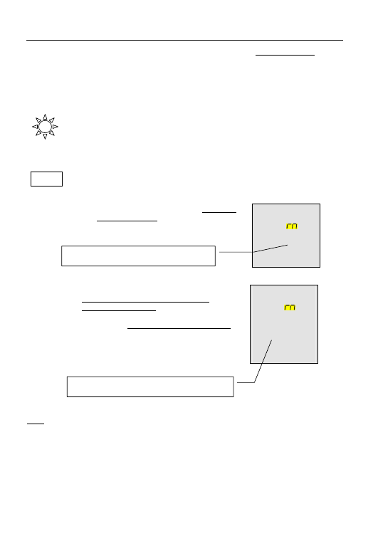
61
8. *PRINTING WITH AN OPTIONAL SERIAL PRINTER (VR2240 ONLY)
The connection from the VR2240 to the printer VRPRINT1 is made using the infra red data
lead VRTL1, in conjunction with printer adaptor cable TL130 (all items sold separately).
To transfer the stored data from the VR2240 to the printer, follow the directions below.
1. Turn the rotary switch to the RS232 position. (In the case of the VR2230,
this position is marked “CAL” and is only used at the point of manufacture
and is of no use to the end user of the instrument.)
3. Using the FUNC key, select the modes "Prn ALL" or "Prn n1 n2", to display
the following screens respectively:
9
Press GO to start printing all of the
stored test results.
9
Press
ESC to stop printing immediately.
P
All 125
P
13
25
9
Press
GO to start printing the test results
from memory locations n1 to memory
locations n2 inclusive. Note that the printing
order is that of the increasing value of the
parameter P, NOT memory location order.
Ensure the range n1 to n2 cover all the
results you need.
9
Press
ESC to stop printing immediately.
Note Transmission speed on the printer is set to 4800 baud to match the output from the
VR2240.
* VR2240 only
FUNC
Indicates the memory cell which will be printed as the
last one.
indicates the total number of results stored in
memory.

62
9. OPTIONAL ACCESSORIES & MAINTENANCE
Accessories
Infra red data lead
*VRTL1
Download
software
*VRSOFT1
Mini
printer
*VRPRINT1
Data Lead VRPRINT1 to VR2240
*TL130
Test lead (GB 13A plug)
TL206
Fused test lead set
TL54
Cleaning
Maintenance consists of periodic cleaning.
The exterior of the instrument can be cleaned with a dry clean cloth to remove any oil,
grease or grime. Never use liquid solvents or detergents.
Repairs or servicing not covered in this manual should only be performed by qualified
personnel.
Calibration
The recommended calibration interval is 12 months.
Martindale Electric will carry out routine calibration (on a chargeable basis) if the
instrument is returned, carriage paid, to the address on the final page of this document.
Alternatively, a chargeable collection and return service is available. Please call our
calibration and service department on 01923 650620 for further details.
Storage Conditions
The Veritest should be kept in warm, dry conditions away from direct sources of heat or
sunlight and in such a manner as to preserve the working life of the instrument.
Warranty
Faults in manufacture and materials are fully guaranteed for 24 months from date
of invoice and will be rectified by us free of charge, provided the unit has not been
tampered with and is returned to us with its housing unopened. Damage due to
dropping, abuse or misuse is not covered by the guarantee. Nothing in these
instructions reduces your statutory rights.
* VR2240 only
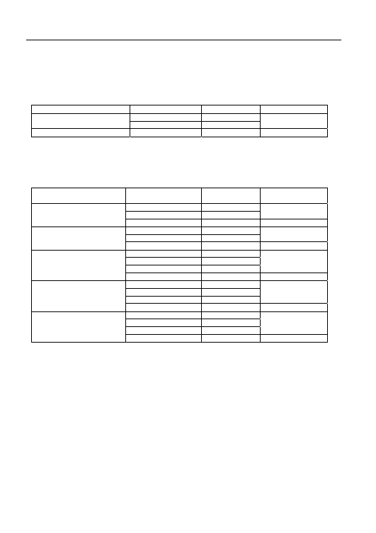
63
10. TECHNICAL
SPECIFICATIONS
10.1. TECHNICAL
FEATURES
Accuracy is indicated as [% of reading + number of digits]. It refers to the atmospheric
conditions listed in paragraph 10.2.1.
Continuity (Low
Ω
)
Test mode
Measuring range (
Ω) Resolution
(
Ω)
Accuracy
0.01 - 19.99
0.01
AUTO, R+, R-
20.0 - 99.9
0.1
±(2% rdg + 2 dgt)
R+TIMER, R-TIMER
0.01 - 9.99
0.01
±(2% rdg + 2 dgt)
Test current
>200mA DC up to 16
Ω (include the resistance of the calibration)
40mA DC from 16
Ω to 99.9Ω
Test current resolution
1mA
Open circuit Test Voltage
9V
Insulation resistance (R
ISO
)
Rated Test voltage (V)
Measurable range (M
Ω)
at rated test voltage
Resolution (M
Ω)
Accuracy
0.05 - 19.99
0.01
20.0 - 49.9
0.1
±(2% rdg + 2 dgt)
50*
50.0 - 99.9
0.1
±(5% rdg + 2 dgt)
0.10 - 19.99
0.01
20.0 - 99.9
0.1
±(2% rdg + 2 dgt)
100*
100.0 - 199.9
0.1
±(5% rdg + 2 dgt)
0.23 - 19.99
0.01
20.0 - 199.9
0.1
200 - 249
1
±(2% rdg + 2 dgt)
250
250 - 499
1
±(5% rdg + 2 dgt)
0.25 - 19.99
0.01
20.0 - 199.9
0.1
200 - 499
1
±(2% rdg + 2 dgt)
500
500 - 999
1
±(5% rdg + 2 dgt)
0.90 - 19.99
0.01
20.0 - 199.9
0.1
200 - 999
1
±(2% rdg + 2 dgt)
1000
1000 - 1999
1
±(5% rdg + 2 dgt)
Automatic selection of the measuring range
Open circuit voltage
Rated voltage test –0% +10%
Short circuit current
<3,0mA - 500V
<2,0mA - 50V, 100V, 250V, 1000V
Test current on load: >1mA @ V
Test
across R
load
=(1000 x V
Test
)
Ω
If the instrument measures a voltage higher than 30V, the instrument does not perform the test.
RCD tripping tests
Type of RCD
AC, A
Range of phase to earth voltage:
(100 - 265) V
Rated tripping currents (I
∆N
)
10mA, 30mA, 100mA, 300mA, 500mA
Test frequency
50Hz
± 0.5 Hz
* VR2240 only
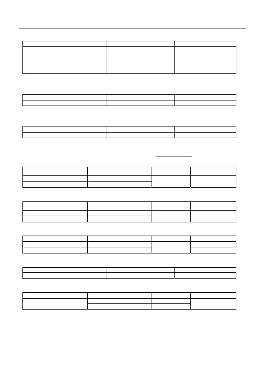
64
Tripping time (t
∆N
)
Measuring range (ms)
Resolution (ms)
Accuracy
½ I
∆N
, I
∆N
0 - 999
2 I
∆N
0 - 200 general
0 - 250 selective
5 I
∆N
RCD 0 - 50 general
0 - 160 selective
1
±(2% rdg + 2 dgt)
NB. For RCD type A 500mA, the MAN x5 and AUTO tests are not available
Contact voltage
Measuring range (V)
Resolution (V)
Accuracy
0 - 2U
t Lim
0.1 -0%,+(10%rdg+2dgt)
U
t Lim
(U
L
): 25V or 50V
Earth resistance R
A
without RCD tripping
Measuring range (
Ω) Resolution
(
Ω)
Accuracy
1 - 1999
1
Ω
±(5% rdg + 2 dgt)
Test current
0.5 I
∆N
of RCD (during RCD U
t
test)
Tripping current Ramp Test for RCD type A and AC (VR2240 ONLY)
RCD with I
∆N
≤ 10mA
Type RCD
Measuring range I
∆N
(mA)
Resolution (mA)
Accuracy I
∆N
AC
(0.5 - 1.4) I
∆N
A
(0.5 - 2.4) I
∆N
0.1 I
∆N
-0%,
+10%
I
∆N
RCD with I
∆N
> 10mA
Type RCD
Measuring range I
∆N
(mA)
Resolution (mA)
Accuracy I
∆N
AC
(0.5 - 1.4) I
∆N
A
(0.5 - 2) I
∆N
0.1 I
∆N
-0%,
+10%
I
∆N
AC voltage
Electrical System
Measuring range (V)
Resolution (V)
Accuracy
Single-phase system
0 - 265
±(2% rdg + 2 dgt)
Two or Three – phase system
0 - 460
1
±(5% rdg + 2 dgt)
Frequency
Measuring range (Hz)
Resolution (Hz)
Accuracy
15.3 – 99.9
0.1
±(0.1% rdg + 1 dgt)
Phase-Neutral Loop Impedance (LOOP Z
S
/I
K
phase to phase or phase to neutral)
Test mode
Measuring range (
Ω) Resolution
(
Ω)
Accuracy
0.03 - 19.99
0.01
P-P and P-N
20.0 -199.9
0.1
±(5% rdg + 2 dgt)
Max peak test current
100V
3.17A
test duration: 80ms
230V
6.64A
test duration: 40ms
400V
11.5A
test duration: 40ms
Accuracy current measurement
±10% I
max Pk
Test voltage
V
PN
100V - 265V 50Hz + 0.5 Hz
V
PP
100V - 460V 50Hz + 0.5 Hz
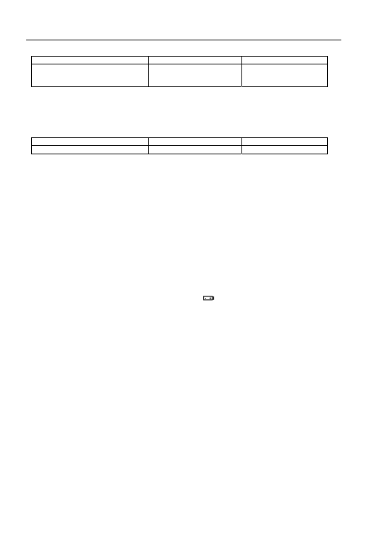
65
Phase-Earth Loop Impedance (LOOP Z
S
/I
K
)
Measuring range (
Ω)
Resolution (
Ω)
Accuracy
0.03 - 19.99
20.0 - 199.9
200 - 1999
0.01
0.1
1
±(5% rdg + 2 dgt)
Max peak test current
100V
3.17A
test duration: 80ms
230V
6.64A
test duration: 40ms
Accuracy current measurement
±10% I
max Pk
Test voltage
V
PE
100V - 265V 50Hz +0.5 Hz
Non-Trip Earth Resistance (R
a15mA
)
Range (
Ω) Resolution
(
Ω)
Accuracy
1 - 1999
1
±(5% rdg + 2 dgt)
Test current
15mA
10.1.1. Safety standards
The instrument complies with:
EN 61010-1 + A2 (1997), EN61557
Insulation:
Class 2, double insulation
Pollution degree:
2
Inside use; max altitude:
2000m
Overvoltage category:
CAT III 460V
∼ P-N-E / 265V∼ to earth
10.1.2. General specifications
Mechanical features
Dimensions: 222(L)
x 162(La) x 57(H)mm
Weight (batteries included):
approx. 1000g
Power supply
Battery type:
6 batteries 1.5 V – LR6 – AA – AM3 – MN 1500
Low battery indication:
The symbol
is displayed when the battery
voltage is too low.
Battery life:
About 40 hours in stand-by or
500
Continuity
(Low
Ω) tests or
250 Insulation (R
ISO
) tests 500V/500k
Ω or
1000 LOOP or RCD or PHASE SEQUENCE
Display
Features: LCD
custom
*Memory:
*350 tests
*Interface
*optical RS232 to print or to download the tests
See accessory list for download leads & software
* VR2240 only
66
10.2. ENVIRONMENT
10.2.1. Environmental working conditions
Reference temperature:
23° ± 5°C
Working temperature:
-10°C – 50 °C
Relative humidity allowed:
<80%
Storage temperature:
-20 – 60 °C
Storage humidity:
<80%
10.2.2. EMC
This instrument was designed in compliance with the EMC standards in force and
compatibility have been tested for EN61326-1 (1997) + A1 (1998)
This instrument complies with the requirements of the European Low Voltage
Directive 72/23/CEE (LVD) and EMC 89/336/CEE, amended with 93/68/CEE.

67
11. SERVICE
Repair & Service
There are no user serviceable parts in this unit. Return to Martindale Electric Company Ltd if
faulty, unless fuse replacement only is necessary. Our service department will promptly quote
to repair any faults that occur outside the warranty period. Please call our service and
calibration department on 01923 650620 for further details.

68
Other products available from Martindale Electric
• 16
th
Edition Testers
• Multifunction Testers
• Calibration Equipment
• Continuity Testers
• Electrician’s Kits
• Full Calibration and Repair Service
• Fuse Finders
• Digital Clamp Meters
• Digital Multimeters
• Microwave Leakage Detectors
• Motor Maintenance Equipment
• Non-Trip Loop Testers
• Pat Testers & Accessories
• Phase Rotation
• Proving Units
• Socket Testers
• Thermometers & Probes
• Test Leads
• Voltage Indicators
• Specialist Metrohm Testers (4 & 5kV)
• Specialist Drummond Testers
Martindale Electric Company Limited
Metrohm House, Penfold Trading Estate, Imperial Way, Watford, WD24 4YY, UK
Tel:+44(0)1923 441717 Fax:+44(0)1923 446900
E-mail: sales@martindale-electric.co.uk
Website: www.martindale-electric.co.uk
© Martindale Electric Company Ltd. 2006 LIT22302240 Rev 9
Registered in England No. 3387451
Wyszukiwarka
Podobne podstrony:
Po przeprowadzeniu pomiarów nasuwają się następujące wnioski
33 rady jak przeprowadzic udana prezentacje 33prez
opis przeprowadzanego pomiaru UFNRESRS2CDR4XQ2ZTKTUD2S3JGIE5LXJFCUSKA
Jak przeprowadzać korekty błędnych zapisów w księgach rachunkowych
Jak przeprowadzić audit wewnętrzny działań zapobiegawczych, Jak przeprowadzić audit wewnętrzny dział
jak przeprowadzic wywiad, formy wypowiedzi
Jak przeprowadzić roczne zebranie we wspólnocie mieszkaniowej
Jak przeprowadzić akcję naborową (skrypt), ZHP, Dla Kadry
Jak przeprowadzić leczniczą głodówkę
Jak dokumentować pomiary czynników szkodliych
Jak przeprowadzić wywiad, Szkolne, Szkoła z klasą 2.0
JAK PRZEPROWADZIĆ REKRUTACJĘ PRACOWNIKA
jak przeprowadzać wywiad
Po przeprowadzeniu pomiarów nasuwają się następujące wnioski
33 rady jak przeprowadzic udana prezentacje 33prez
więcej podobnych podstron