221780A.07.00
Installation and Servicing Instructions
Hepworth Heating Ltd.,
Nottingham Road, Belper, Derbyshire. DE56 1JT
General/Sales enquiries:
Tel: (01773) 824141 Fax: (01773) 820569
One Contact Local Service
To be left with the user
Customer Services:
Tel: (01773) 828100
Fax: (01773) 828070
8010
Glow-worm 45/2 Back Boiler Unit
References in these instructions to British Standards and Statutory
Regulations/Requirements apply only to the United Kingdom.
For Ireland the rules in force must be used.
This is a Cat I
2H
Appliance
BS 6332
BS 5258
For use with specially designed Glow-worm fire fronts only
GC No 44 315 39
2
221780A
1 General
Dimension
A
B
C
D
E
F
G
H
J
K
L
M
N
P
Q
'45/2'
345min 238min
130min
BACK BOILER
547 357 146
185
56
170
340
168
350 418 370max 263max
154 192 155max
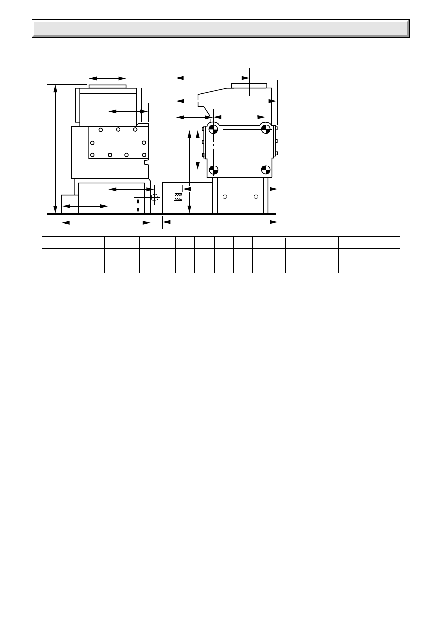
Diagram 1.1
6070
CL
FLUE
CL
FLUE
C
N
A
P
B
E
D
M
L
F
Q
H
J
G
K
Sheet Metal Parts
WARNING. When installing or servicing this back boiler care
should be taken when handling the edges of sheet metal parts
to avoid any possibility of personal injury.
1.1 Statutory Requirements
The installation of this back boiler unit must be carried out by a
competent person in accordance with the current issue and
relevant requirements of:
Manufacturer’s instructions, supplied.
The Gas Safety (Installation and Use) Regulations, The Building
Regulations, The Building Standards (Scotland) Regulations
(applicable in Scotland), Local Gas Undertaking, Byelaws of
the Local Water Company, The Health and Safety at Work Act,
Control of Substances Hazardous to Health, The Electricity at
Work Regulations and any applicable local regulations.
Detailed recommendations are contained in the current issue of
the following British Standards and Codes of Practice,
BS6891, BS5449, BS5546, BS6700, BS5871, BS5440 Part 1
and 2, BS6798, BS1251, BS7478, BS7593, BS7671.
Manufacturer’s notes must not be taken as overriding statutory
requirements.
GAS CONNECTION
Rc
1
/
2
(
1
/
2
in. BSPT)
WATER CONNECTION Rc1
(1in. BSPT) ON RIGHT-HAND
SIDE OR LEFT-HAND SIDE
(R.H. SHOWN)
INSIDE DIAMETER OF
SOCKET FOR 125mm (5in)
NOMINAL DIAMETER FLUE
GENERAL DIMENSIONS
All dimensions are in
millemetres
The instructions consist of three parts, Installation and Servicing
Instructions for the Back Boiler Unit, Installation and Servicing
Instructions for the Fire Front and Instructions for Use, which
includes the Guarantee Registration Card. The instructions are
an integral part of the appliance and must, to comply with the
current issue of the Gas Safety (Installation and Use)
Regulations, be handed to the user on completion of the
installation.
This boiler is for use only with a specially designed Glow-worm
Gas Fire Front, see Table 1.
The boiler is delivered in one pack which contains all the parts
necessary for the installation.
If installing the back boiler unit and fire front at the same time
please read both sets of instructions before starting.
1 General Notes and Information
IMPORTANT NOTICE
The back boiler is fitted with a safety device which will shut it
down if there is a lack of oxygen. If the back boiler shuts down
frequently for no apparent reason the first things to be checked
are the chimney and air inlets into the room. Any problems
found must be put right, by a competent person, before the back
boiler is used again.
This back boiler is for use only on G20 gas.
Wherever possible, all materials, appliances and components
to be used shall comply with the requirements of applicable
British Standards.
Where no British Standard exists, materials and equipment
should be fit for their purpose and of suitable quality and
workmanship.
45/2
BACK BOILER
3
221780A
1 General
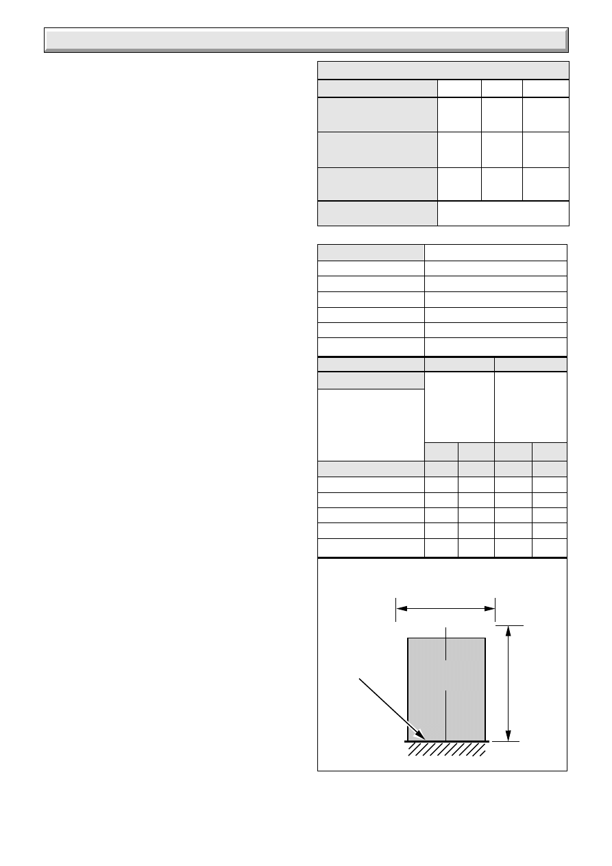
RANGE RATING
NOMINAL
kW
HEAT INPUT
(GROSS)
Btu/h
NOMINAL
kW
HEAT
OUTPUT
Btu/h
BURNER
mbar
SETTING
PRESSURE
in.w.g
12.9
15.4
17.8
44,100
52,500
60,900
3.3 FF2022
9.5
11.7
13.7
32,450
39,800
46,750
8
11.4
15.2
3.21
4.54
6.10
INJECTOR
MARKING
Minimum Medium
Maximum
RANGE RATING TABLE
1.2 Data
Gas connection
Rc
1
/
2
(
1
/
2
inBSPT)
Water connection
Rc1 (1inBSPT)
Electrical supply
230V~50Hz fused 3A
Weight, about
42.5kg (93.7lb)
Water content
5.6Litres (1.23gall)
Injector
3.3mm
Dimensions are given in millimetres (except as noted).
Data Label: Bottom left of control tray.
1.3 Gas Supply
The gas installation shall be in accordance with the current issue
of BS6891.
The supply from the governed meter must be of adequate size
to provide a steady inlet working pressure of 20mbar (8in wg) at
the back boiler.
On completion test the gas installation using the pressure drop
method and suitable leak detection fluid, purge in accordance
with the current issue of BS6891.
1.4 Electrical Supply
WARNING. This back boiler must be earthed.
All system components shall be of an approved type and shall
be connected in accordance with the current issue of BS7671
and any applicable local regulations.
Connection of the back boiler and system controls to the mains
supply should be through a double pole isolating switch, fused
3A having a minimum contact separation of 3mm in both poles.
Alternatively, a fused 3A 3 pin plug and unswitched socket outlet
to the current issue of BS1363 may be used.
Wiring to the back boiler must be PVC (85
o
C) insulated type to
the current issue of BS6500 Table 16, not less than 0.75mm
2
(24/0.20mm).
1.5 Site Requirements
Refer to diagram 1.1 for dimensions appropriate to the back
boiler.
For all types of installation a standard sized builder’s opening is
required, see diagram 1.2.
It is important that the opening is cleared of debris and mortar.
It is recommended that the access hole for pipework into the
fireplace or builder’s opening is either at the left hand or right
hand side of the chimney breast. If access is required at both
sides then it may be necessary to prepare some of the
connections before fitting the back boiler into the builder’s
opening.
The prepared base for the back boiler must be level.
Refer to Table 2 for dimensions of fire front fixing wall face which
must be true.
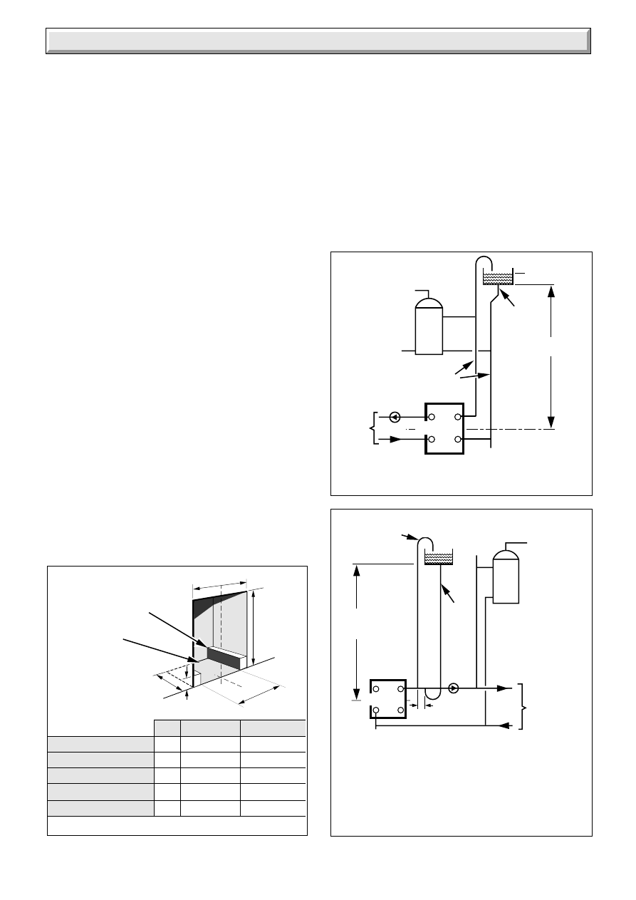
1.6 Water System - Open Vented
This back boiler can be used on an unrestricted open vented
system with the water supply taken from a feed and expansion
cistern, having a head between 1m (3ft3in) minimum and 27m
(90ft) maximum.
Diagrammatic layouts of systems are shown in diagram 1.3 and
1.4.
Dimensions
for
minimum
flat area
(no fixtures)
Dimensions
for fixture or
surround
protection
clearance
3013
FRONT
OPENING
CL
ALL DIMENSIONS IN MM
PREPARED
BASE
Y
X
G.C No.
Teak
Mahogany
T a b l e 1
FIRE TYPE
Miami 3 BBU
37-047-04A 37-047-07A
Melody 3 BBU
37-047-06A
Black Ash 3
37-047-08
Saxony 3
37-047-09
Brown Ember 3
37-047-02
T a b l e 2
FIRE
TYPE
X
Y
X
Y
Miami 3 BBU
642
698
750
836
Melody 3 BBU
642
698
750
836
Black Ash 3
700
660
840
890
Brown Ember 3
795
707
905
892
Saxony 3
700
625
840
860
4
221780A
FULLY PUMPED SYSTEM
(DIAGRAMMATIC)
Diagram 1.4
The COLD FEED PIPE may be connected to the flow
pipe, adjacent to the open vent pipe as shown .
(THERE MUST ALWAYS BE A COLD WATER PATH
TO THE RETURN CONNECTION Of THE BOILER.)
C
L
BOILER
22mm MIN
OPEN VENT
INDIRECT
CYLINDER
MANUAL
AIR VENT
1 metre MIN
27 metres MAX
15mm
COLD
FEED
PUMP
HEATING
CIRCUIT
150mm
MAX
DRAIN COCK
1588
Diagram 1.3
PUMPED HEATING & GRAVITY DOMESTIC
HOT WATER (DIAGRAMMATIC)
1587
C
L
BOILER
27 metres
MAX
PUMP
HEATING
CIRCUIT
22mm
VENT
Refer to
B.S. 5546
28mm
INDIRECT
CYLINDER
15mm
COLD
FEED
DRAIN COCK
1 General
1.7 Sealed Water System
A kit and instructions, part number 426520, is available to
enable the back boiler to be used on a sealed water system.
Please give the serial number of the back boiler when ordering
the kit.
1.8 Hot Water Cylinder
The back boiler is suitable for open vented systems using an
indirect cylinder (including single feed self priming type). The
indirect cylinder must be fitted to the manufacturer’s
recommendations and the system must conform to the
requirements of the current issue of BS5546 and BS6700.
It is recommended that the indirect cylinder be fitted with some
form of temperature control.
1.9 Frost Protection
If the position of the back boiler is such that it may be vulnerable
to freezing it should be protected as specified in the current
issue of BS5422.
It is also recommended that a frost protection thermostat is
fitted.
1.10 Draining Tap
A draining tap must be provided at the lowest point of the
system which will allow the entire system, the back boiler and
hot water cylinder to be drained.
Draining taps shall be to the current issue of BS2879.
1.11 Safety Valve
A safety valve need not be fitted to an open vented system.
C
L
C
L
3012/A
C
B
405mm
A
* CORNER IN-FILL
(not required to be full
depth of opening)
PREPARED
BOILER
BASE
100mm
Diagram 1.2
FRONT OPENING
A
B
C
Miami 3 BBU
350
405 to 580
560 to 590
Melody 3 BBU
350
405 to 580
560 to 590
Black Ash 3
350
406 to 460
560 to 590
*Brown Ember 3
350
510 to 580
560 to 590
Saxony 3
350
406 to 460
560 to 590
1.12 Back Boiler Location
This back boiler MUST NOT be installed in a private garage or
in a room containing a bath or shower or in a room used or
intended to be used as sleeping accommodation.
1.13 BSI Certification
This appliance is certificated to the current issue of BS6332 Part
1 invoking the current issue of BS5258 Part 8 for safety and
performance. It is, therefore, important that no alteration is
made to it without permission, in writing, from Hepworth Heating
Ltd.
Any alteration that is not approved by Hepworth Heating Ltd.,
could invalidate the BSI Certification of the boiler, warranty and
could infringe the current issue of the Statutory Requirements.
5
221780A
1 General
CE Mark
The CE mark on this appliance shows compliance with:
1. Directive 90/396/EEC on the approximation of the Laws of
the Member States relating to appliances burning gaseous
fuels.
2. Directive 73/23/EEC on the harmonization of the Laws of the
Member States relating to electrical equipment designed for use
within certain voltage limits.
3. Directive 89/336/EEC on the approximation of the Laws of
the Member States relating to electromagnetic compatibility.
_________________________________________
This boiler is exempt from the general requirements of the Boiler
(Efficiency) Regulations (1993) and Directive 92/42/EEC by
reason of its conformity to Schedule 3.I.7 of those Regulations
and Article 4.3 of that Directive.
_________________________________________
1.14 Inhibitor
Attention is drawn to the current issue of BS5499 and BS7593
on the use of inhibitors in central heating systems.
If an inhibitor is to be used, contact a manufacturer for their
recommendations as to the best product to use.
If using in an existing system take special care to drain the entire
system, including the radiators, then thoroughly cleaning out
before fitting the boiler whether or not adding an inhibitor.
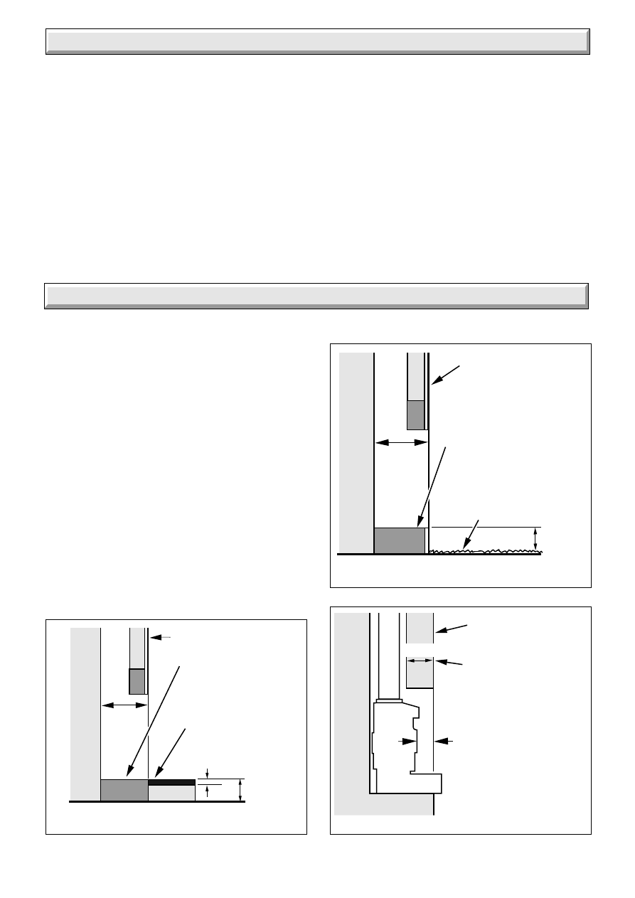
2.1 With Non-combustible Hearth
The back boiler must be installed level with the hearth or above
it, see diagram 2.1.
For minimum dimensions of a hearth see diagram 2.1.
2.2 Combustible Hearth
If the hearth is existing and made of a combustible material the
back boiler must be installed to the dimensions in diagram 2.2.
2.3 With Surround
The combined thickness of the surround and lintel must be
checked, to make sure that the back boiler can be positioned
within the opening to allow easy connection of the flue into the
back boiler flue socket, see diagram 2.3.
The surround requires a minimum opening for access as shown
in diagram 1.2.
2.4 Wall Mounted - that is - Without Surround
or Hearth
If there is to be any combustible material beneath the fire front,
for example, carpet then the base of the builder’s opening must
not be less than 75mm above the floor covering as shown in
diagram 2.2.
Diagram 2.1
INSTALLATION WITH HEARTH
(NON-COMBUSTIBLE)
FIRE FIXING
WALL FACE
350mm
MIN.
TOP OF HEARTH
MUST NOT BE ABOVE
PREPARED BASE
13mm MIN NON-
COMBUSTIBLE
MATERIAL
50mm
MIN.
PREPARED BASE
1589
2 Types of Installation
Diagram 2.3
LINTEL DIMENSION
Diagram 2.2
COMBUSTIBLE HEARTH / WALL
MOUNTED INSTALLATIONS
1591
1590
350mm
MIN.
FIRE FIXING
WALL FACE
N.B.
*Minimum dimension.
This dimension refers to
minimum clearance after
carpet or any floor
covering has been fitted.
PREPARED BASE
TOP OF
CARPET,FLOOR
COVERING OR
COMBUSTIBLE
HEARTH
*75mm
FLUE PIPE
MIN. 90mm
MAX. 115mm
FIRE FIXING
WALL FACE
*
165mm
N.B.
*This dimension can
be increased up to 190mm
if builders opening depth
is at least 375mm deep.
The builder’s opening, with lintel must have minimum dimensions
as shown in diagram 1.2 and 2.3.
6
221780A
BACK
BOILER
UNIT
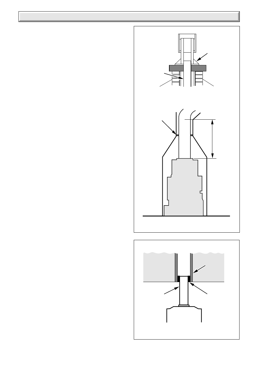
3 Flue and Ventilation
Diagram 3.1
Diagram 3.2
EXISTING FLUE FITTED WITH
APPROVED LINING
FLEXIBLE LINER
CONNECTION
1593
BACK BOILER
APPROVED
SEAL
RIGID
FLUE
LINER
FLEXIBLE
LINER
1592
600mm
SEALING
PLATE
SEALING AND
CLAMPING
PLATE
AIR SPACE
3.1 General
The general recommendations of the current issue of BS5440
Part 1 should be followed.
In all cases the flue should be lined, preferably with a flexible
liner.
It is essential that the flue has an equivalent height of at least
2.5m (8.2ft) measured from the flue connection on the appliance.
The first 600mm, at least, above the draught diverter must be
vertical.
The flue socket is designed to take flue pipe to BS567. If flue
pipe conforming to a different standard is used a suitable
adapter must be fitted and secured to the flue socket. A flexible
flue liner may be used, with connection to the back boiler flue
socket made with a short vertical piece of flexible liner, see
diagram 3.2.
The existing flue may not be completely sound. To prevent any
possibility of leakage, additional sealing MUST be carried out
between the base of the chimney and the flue liner.
The end of the liner at the chimney top must be adequately
sealed and clamped, using proprietary fittings suitable for the
flue liner used, see diagram 3.1.
The flue should, preferably, end above ridge height but at least
above the eaves of a pitched roof. Use a certificated terminal.
If the flue is to pass through or near any combustible material it
should be installed in accordance with the current issue of
BS5440 Part 1. If in doubt seek advice from the local gas
undertaking or Hepworth Heating Ltd.
3.2 Existing Chimney
An existing brick chimney must be thoroughly swept and all
debris cleared away before lining.
Remove any register plates, dampers and the like. Alternatively
it may be locked in the open position.
A flexible flue liner is preferred but a rigid liner may be used, with
connection to the back boiler flue socket made with a short
vertical piece of flexible liner, see diagram 3.2.
Any air supply that enters the builder’s opening other than by the
front opening, that is underdraught openings and the like, must
be completely sealed off.
The sealing plate also prevents debris falling and gives the flue
better insulation, reducing the possibility of condensation, see
diagram 3.1.
Check the flue system efficiency before installing the back
boiler.
3.3 New Chimney
A newly built chimney can be lined with a moisture resistant
lining, such as salt glazed pipe, of an appropriate diameter as
specified in the Building Regulations
In the case of a salt glazed lined flue, it is recommended that a
short vertical length of flue pipe, preferable flexible metallic be
used, fixed and sealed to the back boiler flue socket, made good
with approved packing and parged with fire cement, see diagram
3.2.
If a flue and false chimney breast are to be constructed all
openings for pipework to upper floors etc., must be sealed. The
only opening for the back boiler must be at the front, being of the
dimensions as shown in diagram 1.2.
If a specially built compartment is constructed for the back
boiler, it must conform to the requirements of the current issue
of BS5440 Part 1 and BS5871.
The flue should, preferably, end above ridge height but at least
above the eaves of a pitched roof. Use a certificated terminal.
7
221780A
3 Flue and Ventilation
3.4 Ventilation - Back Boiler and Fire Front
It is important that the room in which the back boiler unit is
installed has adequate air inlets to ensure correct operation as
specified in the current issue of BS5440 Part 2.
Ventilation requirement for this back boiler is:
75cm
2
(12in
2
)
This ventilation area takes into account the total requirement of
the back boiler unit and any of the specially designed gas fire
fronts.
The ventilation openings may communicate direct with outside
air or with an internal room or space (such as a hall) which itself
is provided with a permanent air vent of the same effective area.
The permanent air vent should be in a position which minimises
nuisance to occupants due to draughts.
This vent must NOT be placed in the builder’s opening.
If the appliance is to be installed in a room already containing
another fuel burning unit, the air supply required for this other
unit MUST be added to the figure above.
Any air vent taken through a cavity wall must be ducted.
3.5 Extract Fans
If an extract fan is fitted in the premises, there is a possibility that
if adequate air inlet openings are not provided spillage of the
products of combustion could occur.
When openings are fitted in accordance with the
recommendations of the current issue of BS5440 Part 2, extract
fans should not cause spillage.
Where such a fan installation is found, a clearance of products
test must be conducted as described in the fire front Installation
Instructions.
This test must be carried out with the back boiler fitted with its
fire front.
See also Section 6.3 of these instructions.
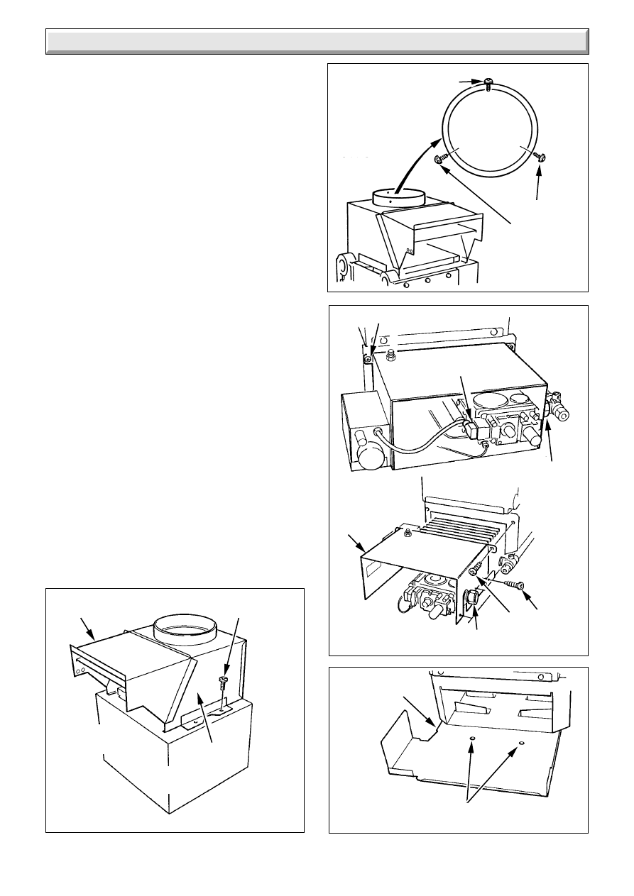
4.1 Preparation
Remove draught diverter, flueway baffle and fittings pack from
carton.
Remove back boiler body assembly from carton.
4.2 Water Connections
IT IS EXTREMELY IMPORTANT THAT NO SERVICE PIPES
ARE ROUTED IN FRONT OF THE BACK BOILER.
If the builder’s opening was previously used for solid fuel all
pipework within should be protected with PVC tape or equal.
Pipework passing through walls of the opening should be
sleeved and made good.
The four heat exchanger connections are tapped Rc1 and are
all on one side of the heat exchanger, see diagram 1.1.
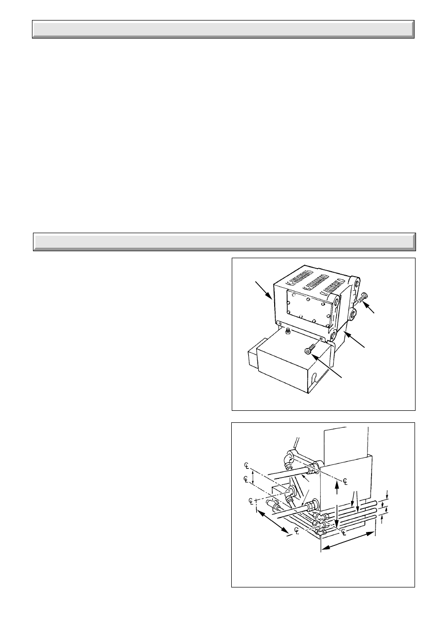
4.3 Pumped Heating with Gravity Domestic
Hot Water
All pipework must comply with the current issue of BS5546.
The domestic hot water flow and return pipes must be 28mm.
The domestic return must be into the connection directly below
the domestic flow connection.
Refer to diagram 1.3 for a diagrammatic layout.
If it is necessary to route pipework from both sides of the
builder’s opening, it is recommended that the heat exchanger is
positioned on the combustion chamber so that the gravity
circuits exit on the same side as the back boiler connections.
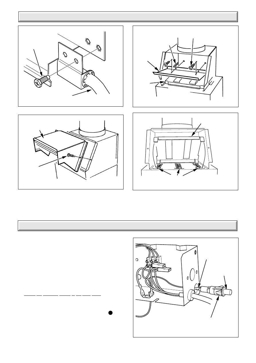
It is recommended that pumped heating connections are
prepiped as in diagram 4.2.
If the heat exchanger connections are opposite hand to that
required, the heat exchanger can be turned, as follows, remove
the four screws securing the heat exchanger to combustion
chamber, see diagram 4.1. Turn heat exchanger, refit the four
screws.
4 Installation
Diagram 4.2
Diagram 4.1
PUMPED HEATING - WITH GRAVITY HOT
WATER PRE-PIPING
5188
1595
HEAT
EXCHANGER
SECURING
SCREWS (2)
SECURING
SCREWS (2)
COMBUSTION
CHAMBER
28mm
168mm
22mm
30mm
MIN.
40mm
MIN.
380mm
MAX.
95mm
196
8
221780A
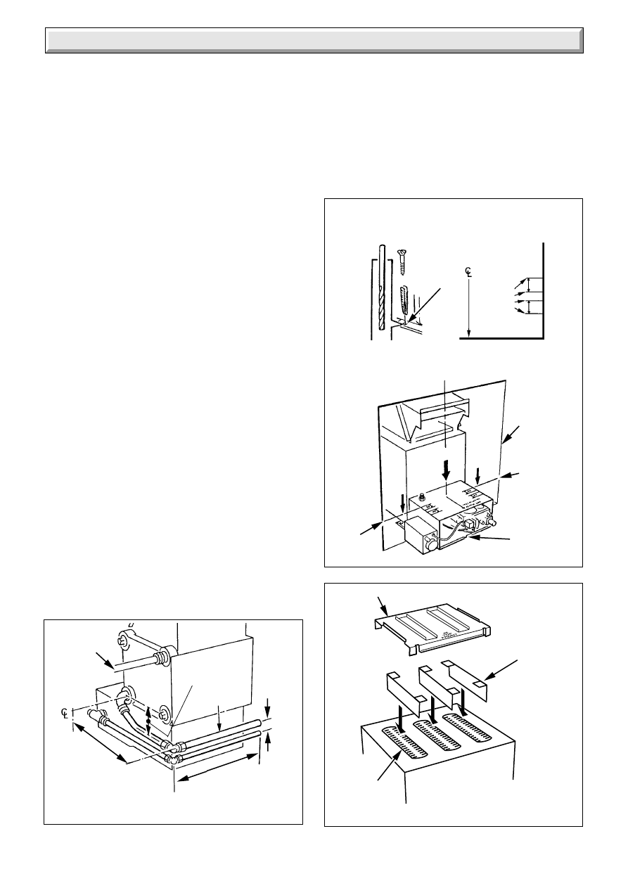
Diagram 4.5
6045
FLUE BAFFLE
FRONT OF
BACK BOILER
FLUEWAY
FLUEWAY
BAFFLES
Diagram 4.4
8014
INSTALLATION
CENTRE LINE
'A'
'A'
'Y'
LIMIT
MARKS
FIRE
FIXING
LIMIT
MARKS
INSTALLATION
CENTRE LINE
45
56
FIRE
FIXING
WALL
FACE
NOTCH
LIMIT
MARKS
VIEW ON
ARROWS
'Y'
VIEW ON
ARROWS
'A'
FIXING
HOLE(S)
7mm Drill
Diagram 4.3
PUMPED HEATING
& HOT WATER PRE-PIPING
1596
380mm
MAX.
30mm
MIN.
22mm
95mm
22mm
196
4.4 Pumped Heating and Hot Water
The pumped flow connection must be diametrically opposite to
the pumped return connection.
Refer to diagram 1.4 for a diagrammatic layout.
If it is necessary to route pipework from both sides of the
builder’s opening it is recommended that the heat exchanger is
positioned on the combustion chamber such that the flow pipe
exits on the same side as the back boiler connections.
It is recommended that the pumped return is prepiped as in
diagram 4.3.
If the heat exchanger connections are opposite hand to that
required, turn in the same manner as described in Section 4.3
paragraph 7.
4.5 Pump
Isolating valves, integral if possible, must be fitted each side of
the pump.
4.6 Gas Supply
The gas installation must be fitted in accordance with the
recommendations of the current issue of BS6891.
See diagram 1.1 for position of gas connection.
It is recommended that the gas supply enters the builder’s
opening on the right hand side.
If the gas supply enters from the left hand side it will be
necessary to route the pipe behind the combustion chamber
before final fixing, see diagram 4.2 and 4.3.
4.7 Positioning the Back Boiler
To position the back boiler lift by the casting and place centrally
in the builder’s opening. The installation centre line is marked
on the combustion chamber extension and by a notch on the
front edge of the floor protection plate.
The back boiler must be positioned so that a line across the
opening of the fire fixing wall face falls between the appropriate
front and rear limiting marks, see diagram 4.4.
The easiest method of aligning the back boiler is to use a
straight edge across the top of the combustion chamber
extension. It is important that the back boiler is square to the fire
front fixing wall face.
Check that the back boiler is level. If packing is required to
adjust the level of the back boiler, use metal shims and pack
under the full width of the base.
Mark through the fixing holes each side of the combustion
chamber, see diagram 4.4. Remove the back boiler. Drill two
holes to accept the plugs and fixings provided.
If access to the fixing holes shown in diagram 4.4 is difficult, use
the alternative method described in Section 4.8 otherwise
proceed as Section 4.9.
4 Installation
9
221780A
4 Installation
Diagram 4.6
Diagram 4.7
5202
5203
FRONT OF
BACK BOILER
HEAT
EXCHANGER
DRAUGHT
DIVERTER
SCREW(4)
FLUE COLLECTOR
ASSEMBLY
SOCKET
FRONT
No.8 X
1
/
2
SCREWS
(BLACK)
Fully fit No.8 X
3
/
8
screw into rear of
socket.
Centralise flexible
flue liner using the
2 No. 8 x
1
/
2
screw
provided.
No.8 X
3
/
8
SCREWS
REAR
4.8 Alternative Back Boiler Fixing
Position the back boiler as described in Section 4.7 paragraphs
1 to 3.
Carefully disconnect the electrical plug from the gas valve and
undo the four screws securing the combustion chamber extension
and remove, see diagram 4.8.
Mark position of fixing holes on each side of the floor protection
plate, see diagram 4.9. Remove back boiler from the opening.
Drill two holes to accept the plugs and fixings provided.
4.9 Positioning the Back Boiler - continued
Insert the 3 flueway baffles into the top of the heat exchanger, see
diagram 4.5.
Fit the flue baffle on top of the heat exchanger ensuring that the
four corners are correctly located into the flueways, see diagram
4.5. The flueway baffle is marked “TOP FRONT”.
Fit the draught diverter onto the heat exchanger with the four
screws provided in the fittings pack, see diagram 4.6. taking care
not to damage the seal.
Where a flexible flue liner is being used, fully fit the No8x
3
/
8
in self
tapping screw provided into the rear of the flue socket as in
diagram 4.7.
Reposition the back boiler into the builder’s opening and secure
to the prepared base with the screws provided. Connect the
system pipework to the back boiler unit/preplumbed pipework.
Refit the combustion chamber extension, if previously removed.
Connect gas supply to gas service cock. Leave gas service cock
in the Back Boiler/Fire “OFF” position, see diagram 6.2.
If a flexible liner is being used, position the liner in to the flue
socket. Using two No8x
1
/
2
in self tapping screws coloured black,
from the fittings pack, screw through the two remaining holes in
the flue socket to centralise and secure the flue liner, see diagram
4.7. Seal with a suitable fire clay cement.
Diagram 4.8
Diagram 4.9
8015
SECURING SCREW
UNION NUT
UNION
NUT
GAS VALVE
ELECTRICAL
PLUG
SECURING
SCREWS
ALTERNATIVE
FIXING HOLES
1602
COMBUSTION
CHAMBER
EXTENSION
AND BURNER
ASSEMBLY
FLOOR
PROTECTION
PLATE
10
221780A
Diagram 5.3
8019
CABLE
CLAMP
EARTH STUD
Diagram 5.2
Diagram 5.1
5 Electrical Wiring
8011
MAINS
CABLE
THERMOSTAT
CAPILLARY
TO R.H.
PHIAL
POCKET
CABLE
CLIPS
CAPILLARY
CLIPS
MAINS
FROM
R.H.S.
CAPILLARY
CUT-OUT
SECURING SCREW
8012
GAS VALVE
ELECTRICAL PLUG
5.1 General
WARNING. This boiler must be earthed.
ISOLATE THE ELECTRICAL SUPPLY BEFORE DOING ANY
WIRING.
All of the electrical installation must be correctly earthed and be
in accordance with the current issue of BS7671 and be carried
out by a competent person.
The mains supply required is 230V~ 50Hz, fused at 3A. A
double pole isolating switch, having a minimum contact
separation of 3mm in both poles should be used.
The mains cable should be PVC heat resistant to 85
o
C the
current issue of BS6500 Table 16, not less than 0.75mm
2
(24/
0.20mm).
Make sure that there is sufficient cable slack to ease future
servicing or replacement.
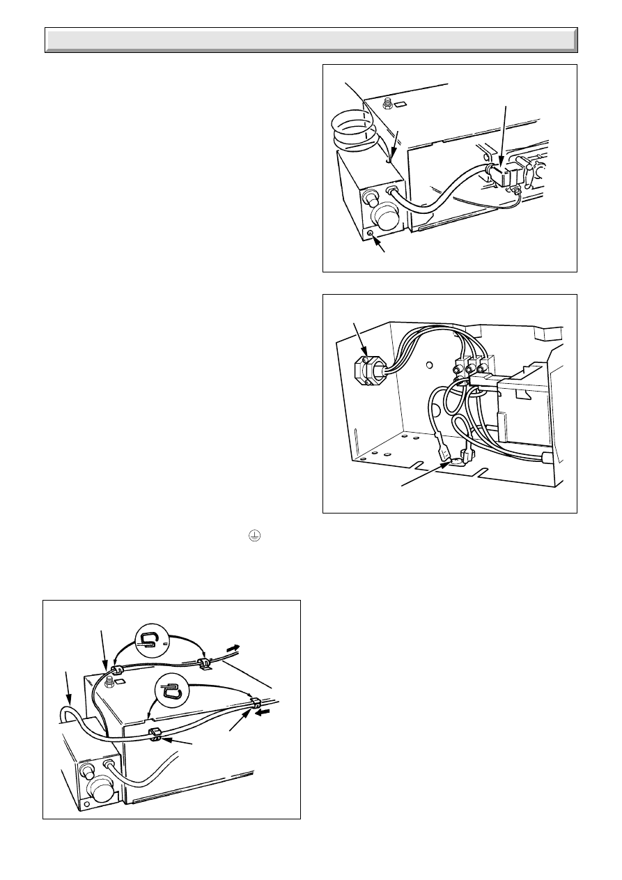
It is preferable to have the electrical supply cable coming from
the left hand side of the builder’s opening.
If however, it must come from the right hand side, it must be
secured under the front edge of the combustion chamber
extension using the two cable clips, from the fittings pack, as
shown in diagram 5.1.
Make sure that all cables are routed well clear of hot surfaces.
5.2 Access to the Boiler Control Box
Disconnect the gas valve electrical plug, (if not already removed)
see diagram 5.2.
Remove the electrical control box securing screw and lift the
box upwards to release, see diagram 5.5.
5.3 Control Box Wiring
Thread the cable through the rear of the box, see diagram 5.3.
The mains cable outer insulation must not be cut back external
to the clamp.
When making connections, make sure that the earth conductor
is made of a greater length than the current carrying conductors,
so that if the cable is strained the earth conductor would be the
last to become disconnected.
Connect the incoming mains earth conductor to the
terminal
on the terminal block, see diagram 5.3 and 5.4.
Connect the incoming mains neutral conductor to N and boiler
control live to L
s
.
11
221780A
5 Electrical Wiring
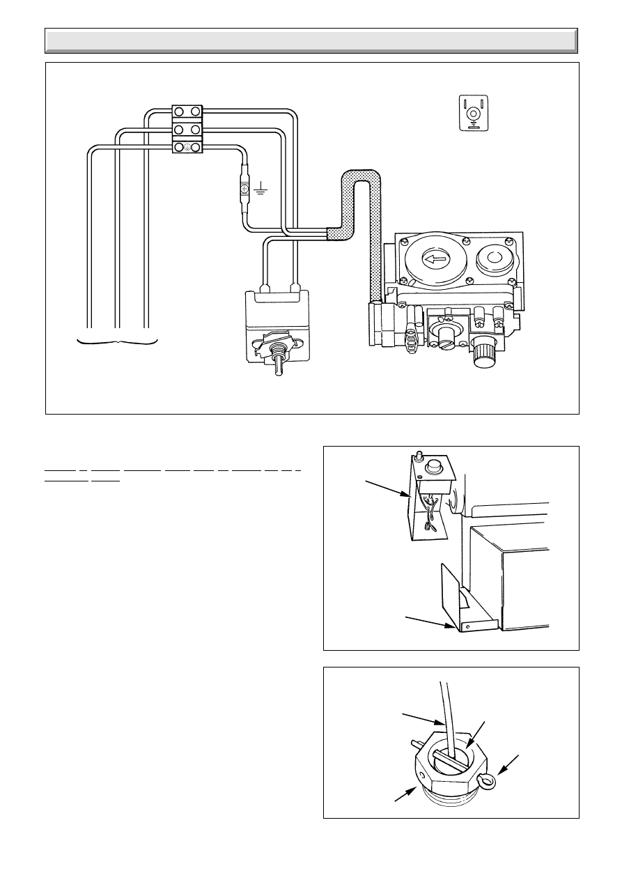
5.4 Testing - Electrical
Checks to ensure electrical safety must be carried out by a
competent person.
After installation of the system, preliminary electrical system
checks as below should be carried out,
1. Test insulation resistance to earth
of mains cable.
2. Test the earth continuity and short
circuit of all cables.
3. Test the polarity of the mains.
5.5 Control Box Refitting
Refit the control box making sure that the control thermostat
capillary is positioned so that it passes through the cutout in the
control box panel, see diagram 5.2.
Secure with screw previously removed, see diagram 5.2.
Refit the gas valve electrical plug.
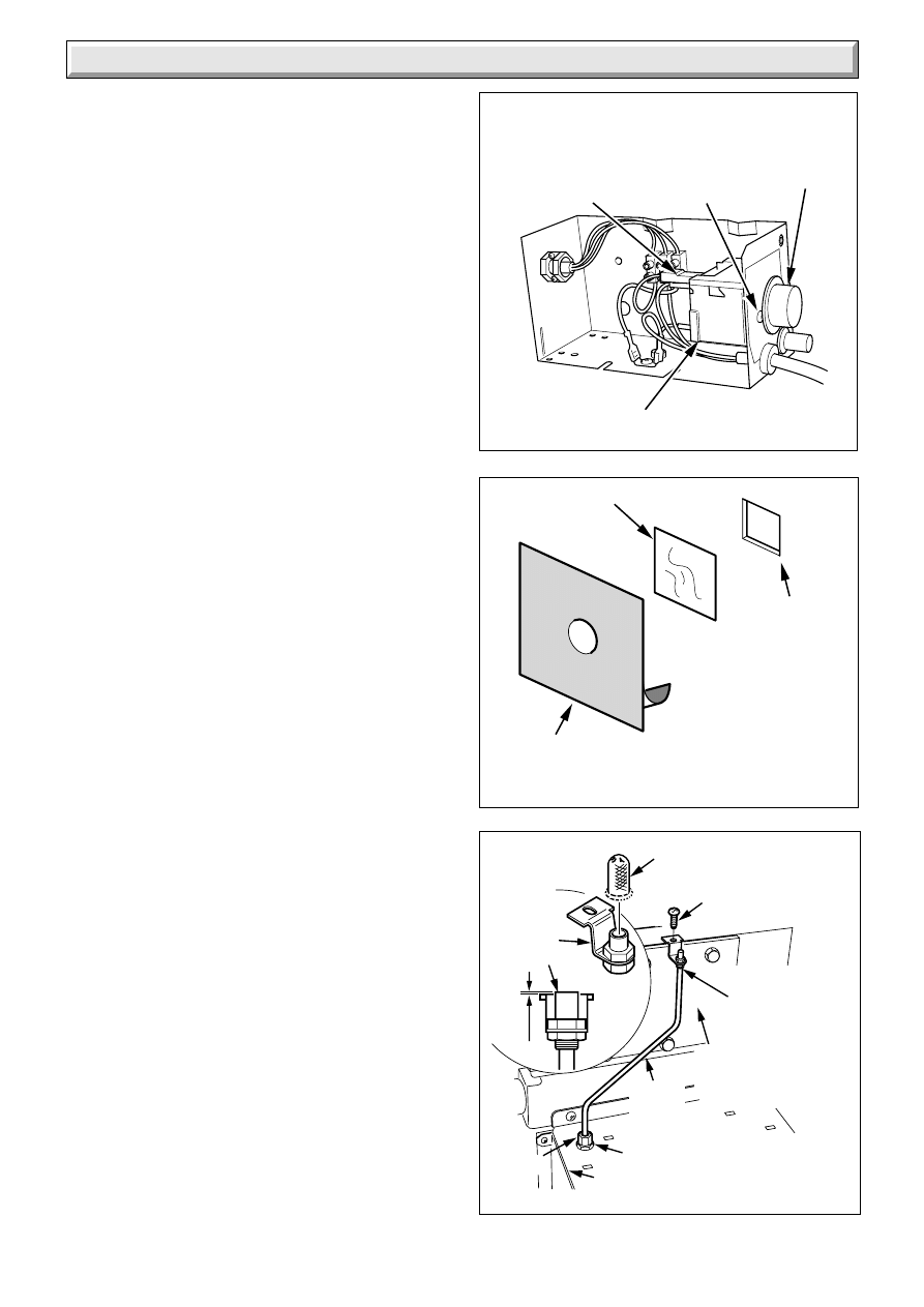
5.6 Control Thermostat Phial
Unwind the capillary so that it will be well clear of any part of the
back boiler which becomes hot and insert it fully into the pocket,
see diagram 5.6.
Secure with location washer behind the split pin.
If the phial pocket is on the right hand side use the cable clips
supplied in the fittings pack. Secure the capillary, see diagram
5.1. Check that the capillary is not touching any hot surfaces.
Diagram 5.5
Diagram 5.6
1870
8021
PHIAL
POCKET
RETAINING
SPLIT PIN
LOCATION
WASHER
CONTROL
BOX
FLOOR
PROTECTION
PLATE
CONTROL
THERMOSTAT
CAPILLARY
8082
Diagram 5.4
N
L
E
N
GAS VALVE
BLUE
BLACK
E
N
THERMOSTAT
NC
C
BROWN
BLACK
VIEW OF PLUG
WHEN REMOVED
GREEN/YELLOW
230V ~ 50Hz
MAINS SUPPLY
FUSED AT 3 AMP
GREEN/
YELLOW
L
Ls
12
221780A
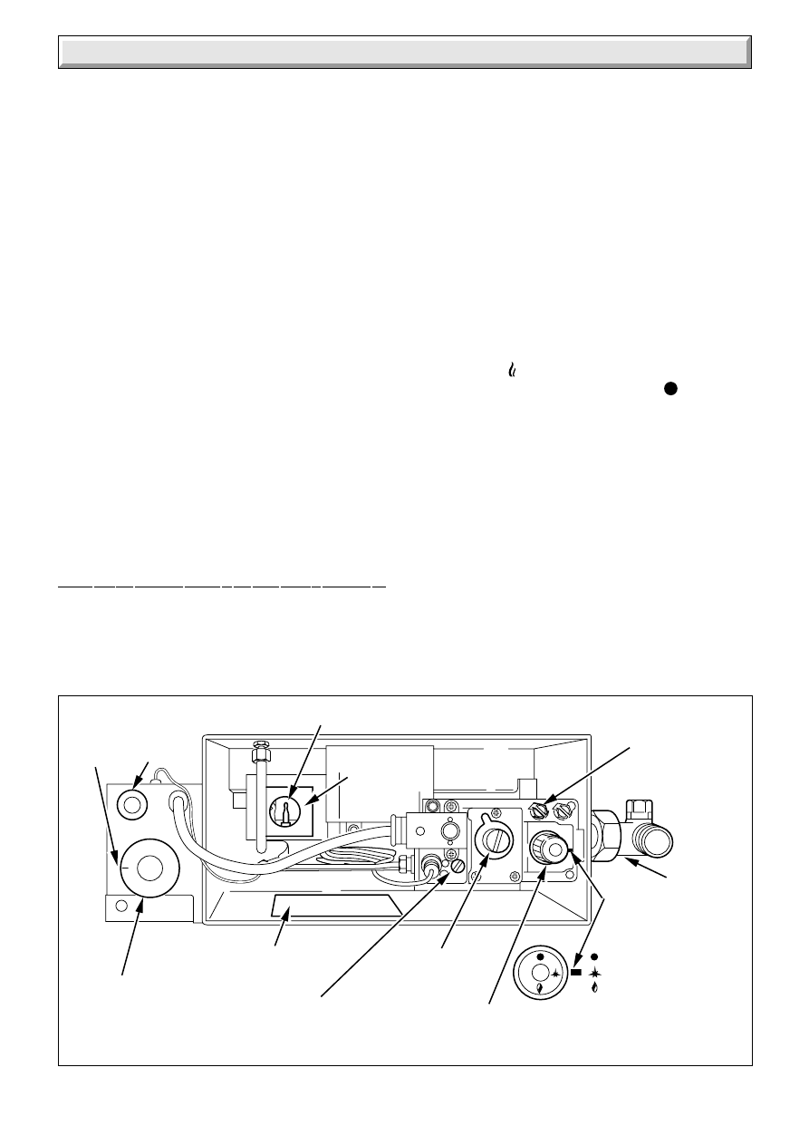
6 Commissioning
Diagram 6.1
'D'
PIEZO
UNIT
BUTTON
'L'
BOILER
DATA
BADGE
SETTING
POINT
'M' VIEWING
WINDOW
8016
'E' PILOT BURNER
'N'
PILOT
ADJUSTMENT
SCREW
'F'
GOVERNOR
ADJUSTMENT
COVER
SCREW
'A'
GAS VALVE
CONTROL
KNOB
SETTING
POINT
OFF
PILOT/IGNITION
MAIN BURNER
'G'
BURNER
PRESSURE
TEST POINT
'K' GAS
SERVICE
COCK
'B'
THERMOSTAT
CONTROL
KNOB
6.1 Commissioning the Back Boiler
The Back Boiler is fitted with a flue blockage safety device which
will shut it down if there is a lack of oxygen.
The flue blockage safety device assembly incorporates the
electrode, thermocouple and pilot assemblies.
Note: The flue blockage safety device sensing tube is supplied
with the fire front.
The lighting, testing of the boiler and commissioning of the
system can continue, but the lighting of the boiler must be
repeated after fitting the sensing tube.
If the back boiler shuts down frequently for no apparent reason
the first things to be checked are the chimney and air inlets into
the room. Any problems found must be put right, by a competent
person, before the back boiler is used again.
Also, when sensing tube is fitted, check that the filter is not linted
up, see diagram 9.4.
The flue blockage safety device MUST NOT be adjusted or
disconnected.
If replacing use only the correct and approved parts.
Before commissioning the back boiler, the whole of the system
should be thoroughly flushed out with cold water with the
circulation pump removed. Replace the pump, fill the system
and examine for water soundness. Vent air from the system
and pump.
CAUTION. The following work should be done by a competent
person.
Identify the back boiler controls by reference to diagram 6.1.
Open windows and put out all naked lights, cigarettes etc.
Test the gas supply for soundness. Purge air in accordance
with the current issue of BS6891.
Check that the electrical supply to the back boiler is switched off.
Set the control thermostat control knob “B” to “Off” that is, fully
anti-clockwise.
Make sure the control thermostat phial is correctly located, see
Section 5.6.
Remove the back boiler burner pressure test screw “G” and
connect a suitable pressure gauge.
If flue blockage safety device sensing tube is not fitted, remove
the plastic ferrule from the bulkhead connector on the air duct,
replace ferrule after testing/commissioning.
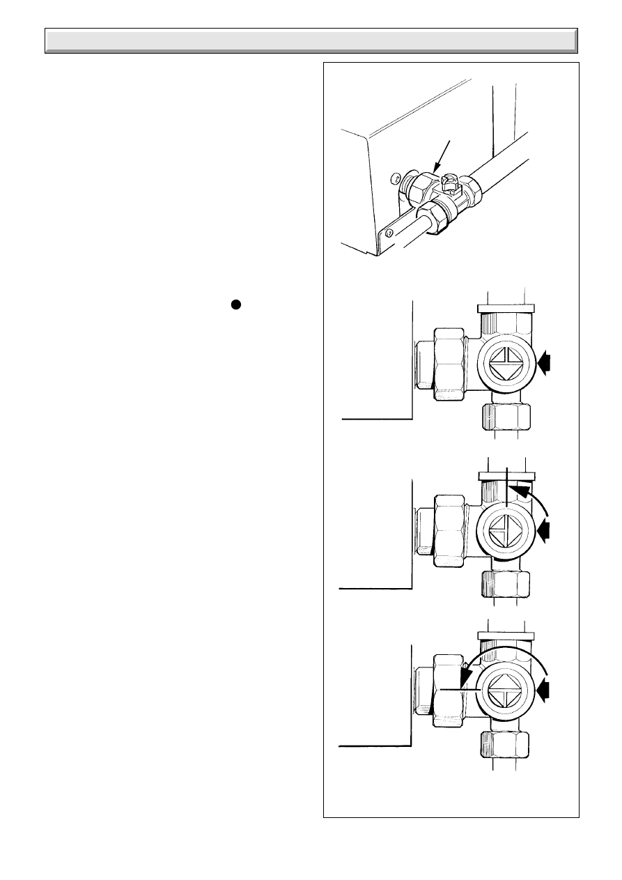
Turn gas service cock “K” to Back Boiler only “On” position, see
diagram 6.2.
Push in slightly and turn gas valve control knob “A” anti-
clockwise until * is against the setting point, now fully push in
and hold, at the same time press and release piezo button “D”
until the pilot burner “E” lights, view through window “M”.
Note, at this stage air may be present in the pilot supply so this
operation may need to be repeated.
When the pilot burner lights, keep gas valve control knob “A”
fully pushed in for about 15 seconds. If the pilot burner fails to
stay alight, repeat the lighting procedure but now keep the
control “A” knob pushed in for a little longer.
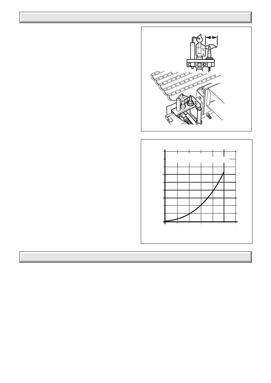
Check that the pilot flame is stable and has a length as shown
in diagram 6.3.
Push in slightly and turn gas valve control knob “A” anti-
clockwise until
is against the setting point.
If the gas valve control knob “A” is turned until
is against the
setting point, a safety lock prevents it being turned on again until
the thermocouple has cooled. NO ATTEMPT SHOULD BE
MADE TO TURN THE CONTROL KNOB “A” UNTIL AT LEAST
3 MINUTES HAVE GONE BY.
Switch on electrical supply and set any remote controls that is,
clock, thermostats, and the like, for heating. Refer to control
manufacturers’ instructions for specific details.
Turn control thermostat knob “B” clockwise until “MAX” is
against the setting point. The main burner should now light.
Test for gas soundness using a suitable leak detection fluid.
The back boiler is supplied preset to the maximum heat input
but may be adjusted to suit design requirements. Refer to Data
Label or Range Rating Table for details.
If adjustment is required, TEN MINUTES after lighting, remove
cover “F” and turn adjustment screw, anti-clockwise to suit
system design heat input.
Should any doubt exist, the gas rate should be checked at the
gas meter.
13
221780A
6 Commissioning
Diagram 6.2
3924 S
1.15 m
3
/h to 1.75 m
3
/h
40.5 ft
3
/h to 61.8 ft
3
/h
GAS SERVICE
COCK UNION
BACK
BOILER
ONLY 'ON'
TURNED
FULLY
CLOCKWISE
BACK
BOILER &
FIRE 'ON'
TURNED TO
MID POSITION
90
°
'OFF'
TURN FULLY
ANTI-
CLOCKWISE
180
°
The rate of the back boiler should be within the range,
Note, if the gas rate is checked, make sure that all other gas
appliances and pilot lights are turned off.
Turn control thermostat knob “B” anti-clockwise to “O” “Off”
position. Remove pressure gauge and replace test point screw
make sure that a gas tight seal is made. Replace governor
cover screw “F”.
Relight the back boiler by turning control thermostat knob “B”
clockwise to “MAX”.
Use the self adhesive arrow from the fittings pack and stick it
against the relevant heat input figure on the Data label.
6.2 Testing the Back Boiler Controls
To check the operation of the flame failure device carry on as
follows:
With the main burner alight, slightly push in gas valve control
knob “A” and then turn it fully clockwise until
is against the
setting point. This will cause the main and pilot burner to go out.
Note, relighting will not now be possible as the safety device in
the gas valve has been activated.
Check that the flame failure device closes within 60 seconds,
indicated by a “click” from the valve.
DO NOT ATTEMPT TO RELIGHT UNTIL AT LEAST 3 MINUTES
HAVE GONE BY.
Relight the pilot and main burner as described in the relevant
part of Section 6.1.
Check that the control thermostat and any external controls
operate the back boiler correctly.
6.3 Clearance of Products
A clearance of products (spillage) test must be carried out after
installation of the back boiler and its fire.
Before fitting the fire front check that the heat exchanger baffle
is fitted and seated correctly.
Make sure that there is no flame disturbance on the back boiler
burner immediately before carrying out test, look through pilot
window “M”, in diagram 6.1.
Details of the necessary procedure to be carried out will be
found under “TEST FOR CLEARANCE OF PRODUCTS” in the
fire front Installation Instruction Booklet.
14
221780A
7 Fire Installation
Fire Front Installation and Servicing Instructions are packed
with the fire front.
7.1 Completion - After Installation of the Fire
Front
Instruct and demonstrate to the user, the efficient and safe
operation of the back boiler, heating and hot water system and
fire front.
Hand the Instructions for Use to the user, for their retention,
making sure that they are understood.
Advise the user that to ensure the continued efficient and safe
operation of the appliance it is recommended that it is checked
and serviced as necessary at regular intervals. The frequency
of the servicing will depend upon the particular installation
conditions and usage, but in general once a year should be
enough.
5197
6 Commissioning
Diagram 6.3
Diagram 6.4
5339
20mm
FLAME
DIMENSION
Pilot Shield
omitted for
clarity
0
10
20
30
40
50
60
70
80
90
5
10
15
20
25
30
WATER PRESSURE LOSS (mm head of water)
WATER FLOW (litres/minute)
45/2 BACK BOILER
PRESSURE LOSS OF APPLIANCE
0
6.4 Commissioning the System
Set all controls to operate the heating system. Adjust pump and
balance the system to give a temperature drop across the boiler
of 11
o
C (20
o
F). At the appropriate flow rate, the resistance of the
back boiler can be found by reference to diagram 6.4.
There should be no undue noise in the pipework or heat
emitters. There must be NO pumping over of water or entry of
air at the open vent pipe above the feed and expansion cistern.
Make sure that the back boiler control knob “B” is turned
clockwise to “MAX” against the setting point, allow the water to
reach maximum working temperature. Examine the system for
water soundness.
Do not attempt to adjust the thermostat calibration screw.
Turn the control thermostat knob “B” anti-clockwise to “Off” and
rapidly drain the system whilst still hot, to complete the flushing
process.
Refill the system, vent and check again for water soundness.
Draw attention, if applicable, to the current issue of the Gas
Safety (Installation and Use) Regulations, Section, 35, which
imposes a duty of care on all person who let out any property
containing a gas appliance.
It is the Law that any servicing is carried out by a competent
person.
Advise that the boiler is fitted with a safety device and refer to
the instructions for use.
Set any remote controls for the system to settings requested by
the user.
Advise the user of the precautions necessary to prevent damage
to the system and building in the event of the heating system
being out of use during frost and freezing conditions.
Reminder, leave these instructions with the user.
Advise the user that the ‘Benchmark’ logbook should be
completed by the installation engineer on completion of
commissioning or servicing.
15
221780A
Diagram 8.2
8 Servicing
Diagram 8.1
SECURING
SCREWS
1613
BURNER
ELECTRODE
BURNER
LOWER
SENSING
TUBE NUT
GAS VALVE
SECURING
SCREW (1)
COMBUSTION
CHAMBER
EXTENSION
BURNER
SUPPORT
8.1 Servicing Notes.
(a) To ensure the continued efficient and safe operation of the
appliance it is recommended that it is checked and serviced as
necessary at regular intervals. The frequency of the servicing
will depend upon the particular installation conditions and
usage, but in general once a year should be enough.
(b) It is the Law that servicing must be carried out by a
competent person.
(c) Remove the fire front.
(d) Refer to the Gas Fire Front Installation and Servicing
Instructions for full details of fire front removal.
(e) After completing any servicing always test for gas soundness
with a suitable leak detection fluid and carry out functional check
on controls.
(f) Unless stated otherwise reassembly of all components is in
the reverse order to that for removal.
(g) The flue blockage safety device MUST NOT be adjusted or
disconnected. If replacing use only the correct and approved
parts.
8.2 Isolation of Services
Having removed the fire front.
Isolate the electrical supply to the back boiler.
Refer to diagram 6.1 to identify the controls.
Turn the gas valve control knob “A” to
“Off” position and turn
the appliance gas service cock to “Fire and Back Boiler Off”, see
diagram 6.2.
8.3 Controls Assembly and Burner.
Disconnect the union at the gas service cock, see diagram 6.2.
If necessary release the control thermostat capillary and the
mains cable from the clips on the combustion chamber extension,
see diagram 5.1.
Disconnect the electrical plug from the gas valve, see diagram
5.2.
Remove the control box securing screw and lift the box upwards
to release, see diagram 5.2.
Disconnect the ignition lead from the piezo unit and remove
from control box, see diagram 9.1.
Temporally refit control box.
Note: On reconnecting the ignition lead to the piezo unit, it may
necessary to temporally remove the control thermostat, see
Section 9.8. Ensure that the control thermostat capillary is
replaced back in the cutout of the control box, see diagram 5.2.
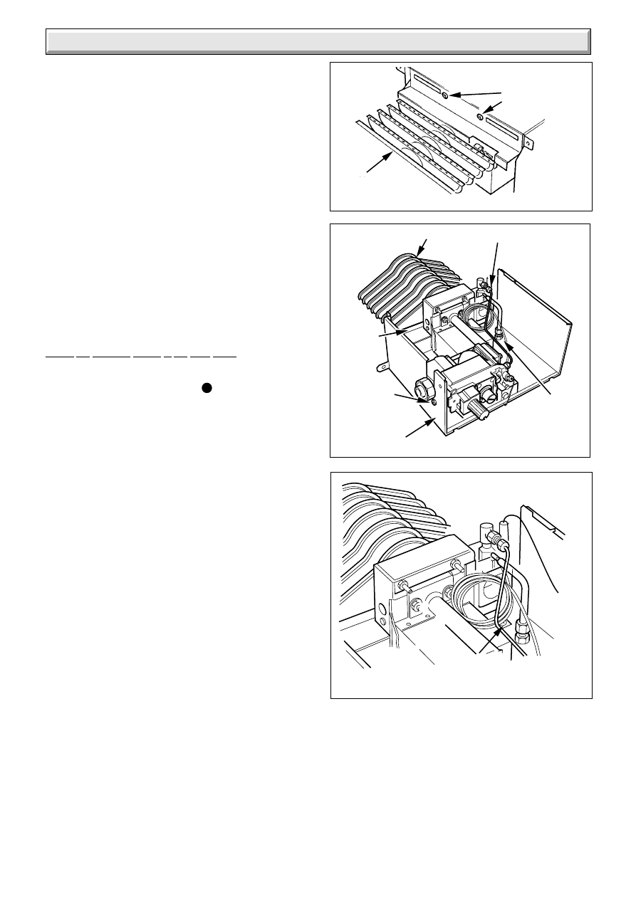
Undo union nut and disconnect the back boiler lower sensing
tube, undo the four combustion chamber extension securing
screws and slide the extension/burner assembly forward to
remove, see diagram 4.8.
Undo the two screws shown in diagram 8.1, which locate the
burner support to the combustion chamber extension.
Turn the combustion chamber extension/burner assembly upside
down.
Undo the lower sensing tube nut, see diagram 8.2.
Undo the two screws shown in diagram 8.2 which locate the gas
valve control to the combustion chamber extension.
The complete gas carrying assembly can now be lifted clear of
the combustion chamber extension.
Diagram 8.3
6078
SCREWS (2)
8018
Undo the screws at the base of the pilot shield, see diagram 8.3.
Remove the pilot shield mounting bracket from the studs on the
burner and remove the pilot shield.
Inspect the pilot for damage or blockage, clean or replace flue
blockage safety device as necessary.
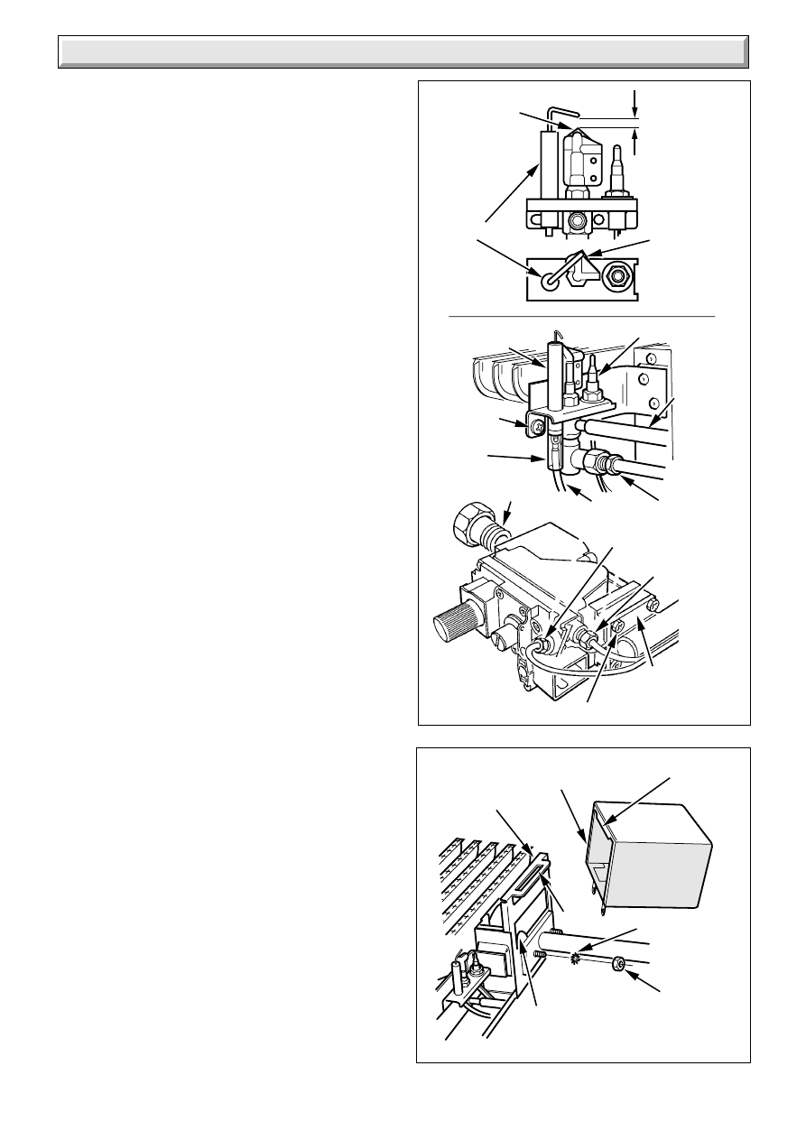
Make sure the spark gap is as diagram 8.4.
Undo the two nuts shown in diagram 8.5 which secure the main
gas manifold to the burner and remove the shakeproof washers,
disengage the lint arrester and then withdraw the main gas
manifold from the burner.
16
221780A
5199
5200
Diagram 8.4
Diagram 8.5
8 Servicing
SHAKEPROOF
WASHER (2)
LUG
LINT
ARRESTER
BURNER
SUPPORT
SLOT
SECURING
NUT (2)
MAIN BURNER
INJECTOR
SECURING SCREW (4)
SUPPLY PIPE
FLANGE
ELECTRODE
THERMOCOUPLE
BBU
LOWER
SENSING
TUBE
PILOT TUBE
NUT
THERMOCOUPLE
NUT
PILOT TUBE
SECURING
NUT
IGNITION
LEAD
SPARK GAP
3
+1
-0.5
FRONT VIEW
TOP VIEW
ELECTRODE
EARTH
POST
EARTH
POST
SILICONE
SLEEVE
SECURING
SCREW(2)
UNION NUT
AND LINER
Clean the lint arrester as necessary.
Inspect the main burner injector for damage or blockage, clean
or replace as necessary using a small amount of approved
jointing compound, on the external thread.
Inspect the ignition lead for wear or damage, clean or replace
as necessary, see diagram 8.4.
Inspect the thermocouple for wear or damage, clean or replace
flue blockage safety device as necessary, see diagram 8.4.
Inspect the electrode for wear or damage, clean or replace flue
blockage safety device as necessary, see diagram 8.4.
Inspect the flue blockage safety device sensing tube filter for
damage or blockage, clean or replace as necessary, see
diagram 9.4.
8.4 Refitting Burner Assembly
When refitting the lint arrester make sure that the lug is fitted into
the slot on the burner support bracket, see diagram 8.5.
Position the pilot shield around the pilot tube, ignition lead and
thermocouple, see diagram 8.3, and refit.
Loosely replace the gas valve control securing screws, see
diagram 8.2. Refit the two screws shown in diagram 8.1, which
locate the burner support to the combustion chamber extension.
Refit the lower sensing tube nut into the bulkhead connection.
Then fully tighten the gas valve securing screws.
Before replacing the burner and controls assembly into the back
boiler the following servicing should be carried out.
8.5 Cleaning Back Boiler Flueways
Remove the burner assembly as Section 8.3.
Undo the two screws securing the fire front sensing tube, if
fitted, and remove, see diagram 8.6.
Undo the two steel screws securing the flue collector assembly,
see diagram 8.7 and remove the flue collector assembly.
Undo the two stainless steel screws securing the diverter plate,
see diagram 8.8 and remove the diverter plate by sliding it
forward.
Lift out the flue baffle, see diagram 8.9.
Lift out the 3 flueway baffles, see diagram 8.9.
Clean the back boiler flue ways with a suitable stiff brush.
Note. A sheet of paper placed in the back boiler combustion
chamber will help in collecting any debris.
To make sure that the flueways are clean, view with the aid of
a mirror or reflector.
8.6 Refitting Flue Collector Assembly and
Final Reassembly
Refit the 3 flueway baffles.
When refitting the flue baffle make sure that the four corner lugs
fit correctly into the back boiler flueways, see diagram 8.9.
When refitting the diverter plate make sure that the plate is
correctly fitted into the guide channels as shown in diagram 8.8
and replace the two stainless steel securing screws.
Refit the flue collector assembly and if fitted the fire front
sensing tube.
Refit the burner and controls assembly to the back boiler.
17
221780A
5079
8 Servicing
Diagram 8.9
Diagram 8.8
Diagram 8.6
Diagram 8.7
5201
1620
6048
FLUE
BAFFLE
FLUE COLLECTOR
ASSEMBLY
SECURING
SCREW
STAINLESS STEEL
SECURING SCREWS(2)
GUIDE
CHANNELS
FLUE
BAFFLE
DIVERTER
PLATE
FIRE FRONT
SENSING TUBE
SECURING
SCREW (2)
FLUEWAY
BAFFLES
9.1 Notes on Replacing Parts.
(a) Replacement of parts must be carried out by a competent
person.
(b) Unless stated otherwise all parts are replaced in the reverse
order to that of removal.
(c) After replacing any gas carrying parts always test for gas
soundness using a suitable leak detection fluid. Also carryout
functional check of controls.
(d) Refer to the Gas Fire Front Installation Instructions for
details of the removal of the fire front.
(e) Isolate the electrical supply to the back boiler.
(f) Remove the gas fire front plinth.
(g) Refer to diagram 6.1 to identify the back boiler controls.
Turn the gas valve control knob “A” clockwise to
“Off”
position. Turn the appliance gas service cock anticlockwise to
“Off” position, see diagram 6.2.
9 Replacement of Parts
Diagram 9.1
RETAINING
TABS
IGNITION LEAD
(BLACK END)
PIEZO
UNIT
8033
18
221780A
FILTER
THRREAD CUTTING
SCREW(Taptite)
SENSING
TUBE
FITTING
ASSEMBLY
FRONT FACE
OF BOILER
CASTING
BACK
BOILER
SENSING TUBE
BULKHEAD CONNECTION
BOILER AIR DUCT
TUBING
NUT
SENSING
TUBE
FITTING
ASSEMBLY
6129
9 Replacement of Parts
Diagram 9.2
8019
Diagram 9.3
NOTE: It is important that the
thermostat is fitted the same
way as shown in diagram
ELECTRICAL
CONNECTIONS
THERMOSTAT
SECURING
SCREW(2)
Diagram 9.4
1mm
9.2 Flue blockage Safety Device Assembly
Gain access as the relevant part of Section 8.3.
Remove lead from electrode.
Pull off back boiler lower sensing tube.
Undo the pilot tube securing nuts and the thermocouple nuts at
gas valve, see diagram 8.4.
Undo the flue blockage safety device assembly securing screws
and withdraw, see diagram 8.4.
When refitting take care not to damage the lower sensing tube
adapter “O” rings.
9.3 Gas Valve
Gain access as the relevant part of Section 8.3.
Disconnect the thermocouple tube nut at the gas valve and ease
out of the valve, see diagram 8.4.
Disconnect the pilot tube nut at the gas valve.
Undo the securing screws to separate the gas valve from the
supply pipe flange. Take care not to damage the “O” ring seal
between the flanges.
Undo the two securing screws to release gas valve from the
combustion chamber extension, see diagram 8.2.
Transfer the union nut and liner to the replacement gas valve
using a small amount of approved jointing compound on the
external thread only.
When fitting the thermocouple only tighten the nut at the gas
valve a quarter turn beyond finger tight.
9.4 Ignition Lead
Gain access as the relevant parts of Section 8.3.
Remove the lead from the electrode and piezo unit.
Fit the silicone sleeve over the new lead.
Fit the black insulated end of the ignition lead to the piezo unit
and the clear end to the electrode.
Push the silicone sleeve into position, see diagram 8.4.
9.5 Main Burner Injector
Gain access as the relevant parts of Section 8.3.
Refer to diagram 8.4 and undo the thermocouple nut and
withdraw the thermocouple.
Undo the pilot tube nut at the gas valve control.
Refer to Section 8.3 paragraph eleven.
When replacing the main burner injector use a small amount of
approved jointing compound on the external thread only.
9.6 Pilot Burner Injector
Should pilot burner injector need replacing, the whole pilot
burner assembly must be replaced.
9.7 Piezo Unit
Gain access as the relevant parts of Section 8.3.
Disconnect the ignition lead from the piezo unit, see diagram
9.1.
Note: To ease the removal of the piezo unit it is advisable to
temporarily remove the boiler thermostat from the control box,
refer to Section 9.8.
Depress the retaining tabs and remove the Piezo unit.
SELF ADHESIVE
ALUMINIUM FOIL
GASKET
MICA WINDOW
PEEL OFF
BACKING
PAPER
OPENING
(PILOT
BURNER)
7886
CONTROL
KNOB
19
221780A
9.8 Control Thermostat
Disconnect the gas valve electrical plug, see diagram 5.2.
Remove the split pin to release the control thermostat phial, see
diagram 5.6.
If the phial pocket and/or the electrical supply is on the right
hand side, release the capillary and/or the main lead from the
clips, see diagram 5.1.
Remove the control box securing screw and lift the box upwards
to release, see diagram 5.2.
Remove the control thermostat knob “B”, see diagram 9.2.
Remove the two securing screws and remove the control
thermostat body.
When fitting the new control thermostat, make sure that the
capillary connection to the control thermostat body is placed at
the top of the control box top.
Refit electrical connections.
Capillary should pass through the cut out on the control box top,
see diagram 5.2. Care should be taken to make sure that the
side plate hooks onto the box before fitting the securing screw.
9 Replacement of Parts
9.9 Viewing Window
Gain access as the relevant parts of Section 8.3.
Remove the old self adhesive aluminium foil gasket and the old
mica window. Replace with a new mica window. Peel off the
backing paper and secure with new self adhesive aluminium foil
gasket, see diagram 9.3. Ensure no air bubbles are trapped
underneath the foil.
Important
Make sure that the mica window fully covers the opening and
that the hole in the aluminium foil gasket is centred over
opening.
9.10 Flue blockage Safety Device Sensing
Tube Fitting
Remove filter, unscrew thread cutting screw and remove sensing
tube fitting assembly, see diagram 9.4.
When fitting new filter, take care not to damage the filter.
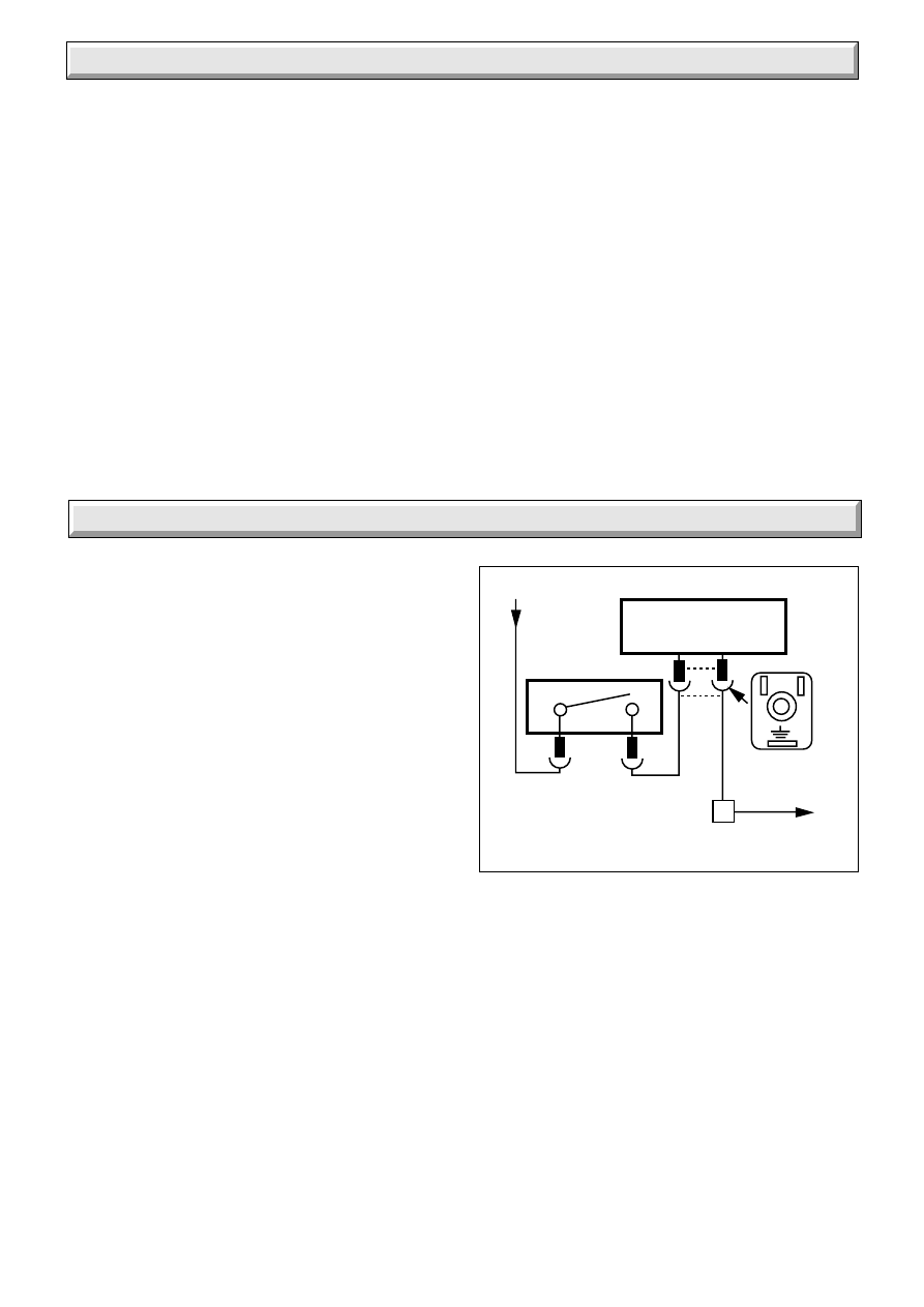
10.1 Electrical
Carryout the preliminary electrical system checks as contained
in a multimeter instruction book.
Refer to functional flow wiring diagram 10.1 and electrical fault
finding chart, diagram 10.2.
On completion of the fault finding task which has required the
breaking and remaking of electrical connections the checks
earth continuity, polarity and resistance to earth must be
repeated.
10.2 Thermocouple
To test the thermocouple, a meter with a range of 0 - 30mV is
required together with a thermocouple interrupter test unit.
Refer to thermocouple fault finding chart, diagram 10.3 and
diagnosis graph, diagram 10.4.
10.3 Back Boiler Pilot and Ignition
To check back boiler pilot/safety device - and ignition, refer to
pilot fault finding chart, diagram 10.5.
10.4 Flue blockage Safety Device
If the device operates and the filter is clean, it indicates there is
a problem with the chimney. Make sure air vents are free from
obstruction, carry out spillage checks as Fire Front Installation
Instructions and put right as necessary.
Diagram 10.1
FUNCTIONAL FLOW WIRING
8084
C
L
s
GAS VALVE SOLENOID
THERMOSTAT
BLUE
BROWN
VIEW OF
PLUG WHEN
REMOVED
BLUE
NC
3
4
N
L
E
N
N
BLACK
10 Fault Finding
20
221780A
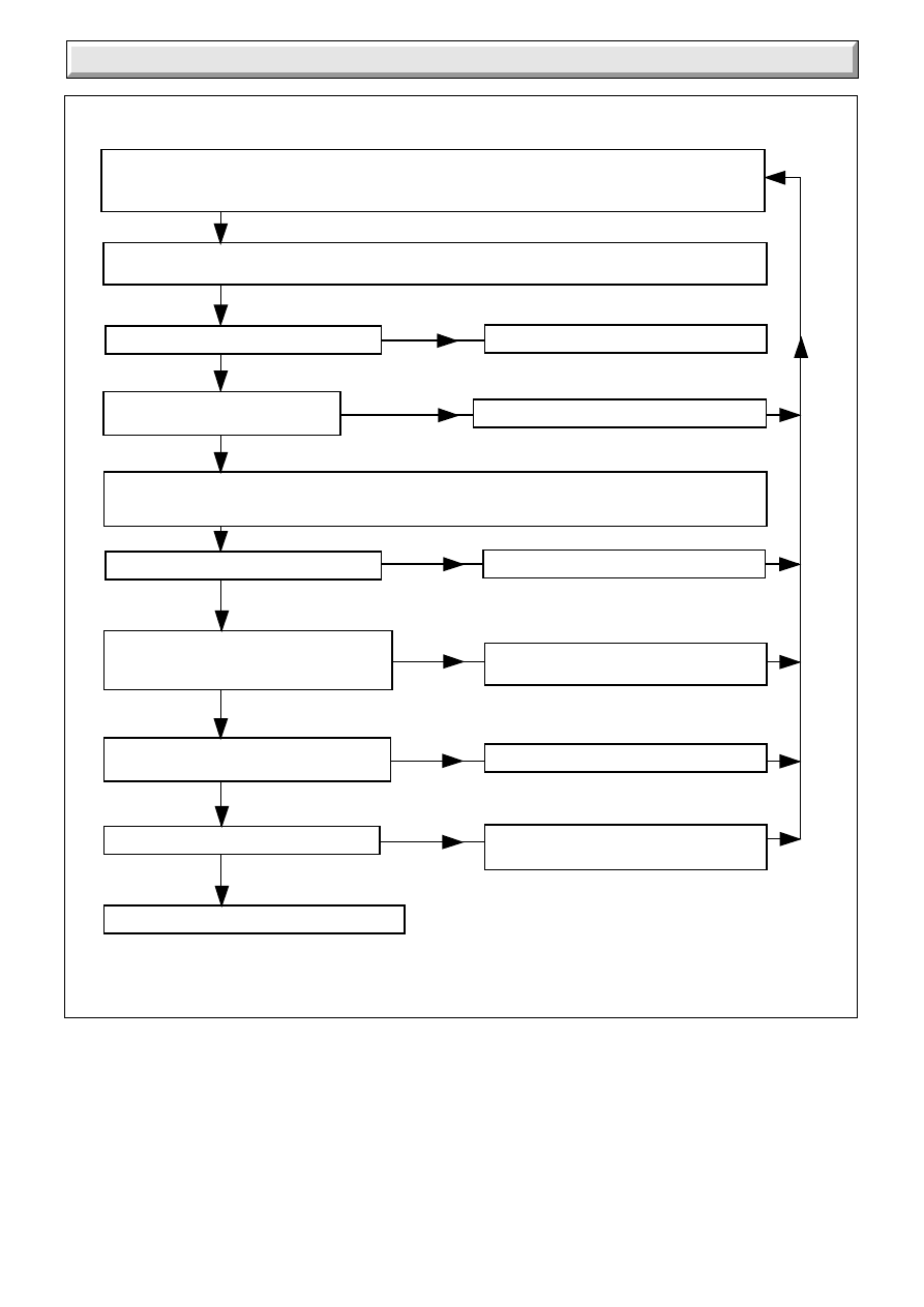
ELECTRICAL FAULT FINDING CHART
4484A
Diagram 10.2
Isolate power supply to the control box. Gain access to the control box and physically check all wires and
connections. Check fuses.
Check that all remote controls, (eg room and / or cylinder thermostats), are making contact for duty.
Turn on the power supply to the control box. Turn on the boiler thermostat and measure the voltage
between C and N.
Is the voltage between 216 and 264 volts.
Check control box wiring and mains supply
Isolate the power supply. Replace thermostat
Is there voltage between NC and N.
216 and 264 volts.
Isolate the power supply to the control box. Remove plug from gas valve and connect
voltmeter between L and N in plug, ensuring no short circuits (mains voltage). Turn on power supply and
measure voltage.
Is the voltage between 216 and 264 volts.
Check control box wiring.
Isolate the power supply to the control box.
Reconnect gas valve. Turn on
power supply. Does main burner light.
Turn off boiler thermostat, measure voltage
across 3 and 4. Is the voltage zero.
Does the main burner extinguish.
Boiler electrical system operating satisfactorily
Isolate power supply.
Replace gas valve.
Isolate power supply. Replace thermostat.
Isolate power supply.
Replace gas valve.
YES
NO
NO
YES
NO
YES
YES
YES
YES
NO
NO
NO
Isolate power supply to the control box. Gain access to the control box and physically check all wires and
connections. Check fuses. Check Flue Blockage Safety Device filter is not blocked, clear if necessary.
Check that all remote controls, (eg room and / or cylinder thermostats), are making contact for duty.
10 Fault Finding
21
221780A
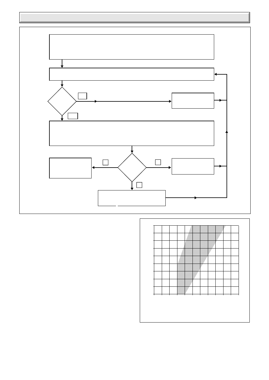
Disconnect appliance thermocouple from the gas valve. Check that all connections are
clean and in good condition. Fit test meter interrupter into the magnet unit. Fit appliance
thermocouple into the test meter interrupter. Check that the flue blockage safety device
sensing filter is clean, if not remove / clean and replace.
NO
YES
Hold down control knob on gas valve. Ignite pilot burner and allow thermocouple to attain
operating temperature. Measure the OPEN CIRCUIT voltage.
Is
voltage
greater
than
15mV?
Faulty thermocouple.
Replace.
Note the open circuit reading then measure the CLOSED CIRCUIT voltage. Note this voltage.
Referring to the diagnosis graph, mark the open circuit voltage on the VERTICAL axis,
and the closed circuit voltage on the HORIZONTAL axis. Note the point where these
two values intersect on the graph.
THERMOCOUPLE
CIRCUIT IS
SATISFACTORY
In
which
area of the
graph is the
intersect
Faulty thermocouple.
Replace.
Faulty magnet unit in gas valve.
Replace .
B
A
C
10 Fault Finding
6131
Diagram 10.3
THERMOCOUPLE
FAULT FINDING CHART
Diagram 10.4
DIAGNOSIS GRAPH FOR BOILER
THERMOCOUPLE CIRCUIT
1429
Closed Circuit Voltage (millivolts)
Open Circuit Voltage (millivolts)
0
2
4
6
8
10 12 14 16 18 20 22
9
11
13
15
17
19
21
23
25
27
A
B
C
.
22
221780A
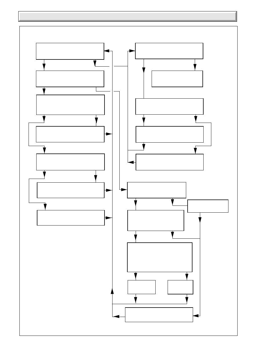
Diagram 10.5
BACK BOILER PILOT FAULT FINDING CHART
10 Fault Finding
PILOT WILL NOT LIGHT
START HERE
Check gas line-open all cocks,
rectify any blockages, purge out
any air. Does pilot light?
Apply match to pilot burner instead
of pressing piezo unit button.
Does pilot light?
Undo tubing nut at pilot burner.
Press gas valve knob.
Does gas flow freely?
Replace faulty flue blockage
safety device.
Undo tubing nut at pilot outlet
of gas valve. Press gas valve knob.
Does gas flow freely?
Change blocked pilot tube.
Change gas valve.
Does pilot stay alight when
gas valve knob is released?
PILOT SATISFACTORY
Does pilot flame envelop
thermocouple?
Replace faulty flue blockage
safety device.
Check thermocouple circuit using
Thermocouple fault finding,
see diagram 10.3.
On pressing piezo unit button is
there a spark across electrode
gap?
Pull ignition lead off electrode.
Hold end of lead close to pilot
burner and operate piezo unit.
Is there a spark across gap?
Pull ignition lead off piezo unit.
Using blade of a screwdriver, touch
unit chassis and leave approx.
4mm gap from connection tag on
piezo unit. Operate piezo.
Is there a spark across gap?
Change
piezo unit.
Change
ignition lead.
Replace faulty flue blockage
safety device.
NO
YES
NO
YES
NO
YES
NO
YES
NO
YES
NO
YES
NO
YES
NO
YES
NO
YES
Check spark gap.
Refer to diagram 8.4.
5278A
23
221780A
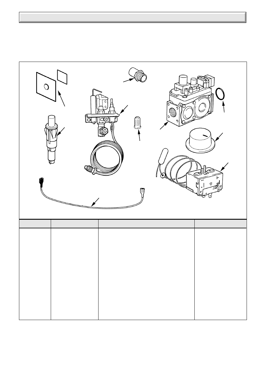
Diagram 11.1
11 Spare Parts
Key No
Part No.
Description
GC Part No
9
5
4
7
2
3
8
6
1
8034
10
1
426766
Multifunctional control
191 264
2
FF2022
Injector - 45/2 BBU
355 159
3
451477
Flue Blockage safety device
4
202518
Control thermostat
191 273
5
204687
Control thermostat knob
6
202713
Piezo unit
7
WW4603
Ignition lead
191 267
8
801236
Mica window and gasket
9
208068
“O” ring
334 658
10
208680
Sensing tube filter
When spare parts are required apply to your local supplier.
Please quote the name of the appliance, Glow-worm 45/2BBU, also the serial number of the back boiler, to be found on the data label
on the combustion chamber extension, see diagram 6.1.
If ordering from British Gas the GC number should also be quoted, together with the GC number of the part.

24
221780A
Because of our constant endeavour for improvement details may vary slightly from those given in these instructions.
Information for the Installer and Service Engineer.
Under Section 6 of The Health and Safety at Work Act 1974, we are required to provide
information on substances hazardous to health.
The adhesives and sealants used in this appliance are cured and give no known hazard in this state.
INSULATION PADS/CERAMIC FIBRE, GLASSYARN
These can cause irritation to skin, eyes and the respiratory tract.
If you have a history of skin complaint you may be susceptible to irritation. High dust levels are
usual only if the material is broken.
Normal handling should not cause discomfort, but follow normal good hygiene and wash your hands
before eating, drinking or going to the lavatory.
If you do suffer irritation to the eyes or severe irritation to the skin seek medical attention.
THERMOSTATS
These contain very small amounts of xylene in the sealed phial and capillary. If broken, under normal
circumstances the fluid does not cause a problem, but in cases of skin contact, wash with cold water.
If swallowed drink plenty of water and seek medical attention.
Control of Substances Hazardous to Health
Wyszukiwarka
Podobne podstrony:
Glow Worm installation and service manual 56 3P BBU UIS
Glow Worm installation and service manual Hideaway 70CF UIS
Glow Worm installation and service manual Ultimate 50CF UIS
Glow Worm installation and service manual Ultimate 60CF UIS
Glow Worm installation and service manual Glow micron 60
Glow Worm installation and service manual Glow micron 40
Glow Worm installation and service manual Hideaway 80BF UIS
Glow Worm installation and service manual Hideaway 50CF
Glow Worm installation and service manual Energy Saver 60 UI
Glow Worm installation and service manual Hideaway 120BF UIS
Glow Worm installation and service manual Hideaway 120CF UIS
Glow Worm installation and service manual Ultimate 40CF UIS
Glow Worm installation and service manual Glow micron 70
Glow Worm installation and service manual Hideaway 100CF UIS
Glow Worm installation and service manual Miami GF UIS
Glow Worm installation and service manual Hideaway 70BF UIS
więcej podobnych podstron