SOI/DT 2002-06 eb
1
599 35 26-84
SERVICE MANUAL
WASHING
ELECTROLUX ZANUSSI S.p.A.
Spares Operations Italy
Corso Lino Zanussi,30
Publication No.
I - 33080 PORCIA /PN (ITALY)
599 35 26-84
Fax +39 0434 394096
Edition: 2002-06-03
EN
Washing machines
&
Washer-Dryers
with EWM2000
Electronic Control
Styling:
Multipanel Built-in
Production: Porcia (IT)
(SW: W2C0145x)

SOI/DT 2002-06 eb
2
599 35 26-84

SOI/DT 2002-06 eb
3
599 35 26-84
Contents
1
General characteristics ......................................................................................................................... 5
2
Control panel........................................................................................................................................ 6
2.1
General features ............................................................................................................................. 6
2.2
Control/Display board...................................................................................................................... 7
2.2.1
Version with display (washing machines and washer/dryers): ................................................ 7
2.2.2
Version without display (washing machines) .......................................................................... 7
2.3
Washing programmes ..................................................................................................................... 8
2.3.1
24-position selector knob....................................................................................................... 8
2.4
Push-button function ....................................................................................................................... 9
2.5
“ON/OFF” Button........................................................................................................................... 10
2.6
Washing cycle options................................................................................................................... 10
2.6.1
“Prewash” button................................................................................................................. 11
2.6.2
“Stains” button..................................................................................................................... 11
2.6.3
“Intensive” / “Heavy soil” button ........................................................................................... 11
2.6.4
“Short”/ “Very short” button (“Light soil” / “Daily”).................................................................. 11
2.6.5
“Level of soiling” button ....................................................................................................... 11
2.6.6
“BIO” button ........................................................................................................................ 11
2.6.7
“Half load” button................................................................................................................. 11
2.6.8
“Super rinse” or “Extra rinse” button.................................................................................... 11
2.6.9
“Rinse hold” or “Night cycle” ................................................................................................ 12
2.6.10
“Spin” button ....................................................................................................................... 12
2.6.11
“Reduced spin speed” button............................................................................................... 13
2.7
"Delayed start” button.................................................................................................................... 13
2.8
“No Buzzer” option ........................................................................................................................ 13
2.9
Options for washer-dryers ............................................................................................................. 14
2.9.1
“Electronic drying” button..................................................................................................... 14
2.9.2
“Drying time” button............................................................................................................. 14
2.10
“Start/Pause” button ...................................................................................................................... 14
2.11
Display.......................................................................................................................................... 15
2.12
Programme phase Leds ................................................................................................................ 16
3
Washing programmes (sequence charts)............................................................................................ 17
3.1
Cotton 60
°
C (Jetsystem) ............................................................................................................... 19
3.2
Cotton 60
°
C (Traditional/Eco-ball) ................................................................................................. 20
3.3
Synthetics 40
°
C (Jetsystem) ......................................................................................................... 21
3.4
Synthetics 40
°
C (Traditional/Eco-ball) ........................................................................................... 22
3.5
Hand wash 30º (Jetsystem)........................................................................................................... 23
3.6
30º Hand wash (Traditional) .......................................................................................................... 23
3.7
Drying Cotton (Jetsystem - Traditional).......................................................................................... 24
3.8
Drying Synthetics (Jetsystem - Traditional).................................................................................... 24
3.9
“FUCS” ......................................................................................................................................... 25
3.9.1
Examples of operation of the unbalancing control function ................................................... 25
3.10
Spins ............................................................................................................................................ 27
3.10.1
Spin IMP_C0_INP_SECT.................................................................................................... 27
3.10.2
Spin IMP_C0_SP_SECT ..................................................................................................... 27
3.10.3
Spin IMP5 ........................................................................................................................... 27
3.10.4
Spin IMP7 ........................................................................................................................... 27
3.10.5
Spin IMP4 ........................................................................................................................... 28
3.10.6
Spin IMP6-RINSE................................................................................................................ 28
3.10.7
Spin IMP6_INP_SECT ........................................................................................................ 28
3.10.8
Spin IMP6_SP_SECT.......................................................................................................... 29
3.10.9
Spin IMP6_QUICK .............................................................................................................. 29
3.10.10
Spin IMP_SR ...................................................................................................................... 29
3.10.11
Spin IMP_BEFORE_CF ...................................................................................................... 29
3.10.12
Spin IMPCF_01_AC ............................................................................................................ 30
3.10.13
Spin IMPCF_01_DC............................................................................................................ 30
3.10.14
Spin IMPCF_QUICK............................................................................................................ 30
4
Technical characteristics..................................................................................................................... 31
4.1
EWM2000 Electronic control unit................................................................................................... 31
4.1.1
Memories of the microprocessor (main PCB)....................................................................... 32
4.2
Analog pressure switch (electronic) ............................................................................................... 33

SOI/DT 2002-06 eb
4
599 35 26-84
4.3
Instantaneous door safety device .................................................................................................. 34
Operation principle ............................................................................................................................. 34
4.4
Detergent dispenser ...................................................................................................................... 35
4.5
Power supply to the motor............................................................................................................. 36
4.5.1
AC/DC Converter ............................................................................................................... 36
4.6
Circulation pump ........................................................................................................................... 37
4.7
Heating ......................................................................................................................................... 37
4.8
Drain cycle.................................................................................................................................... 37
5
Drying circuit (washer-dryers) ............................................................................................................. 38
5.1.1
Temperature control ............................................................................................................ 39
5.1.2
Determining the drying time:................................................................................................ 39
6
Diagnostics system............................................................................................................................. 40
6.1
Access to diagnostics and configuration system ............................................................................ 40
6.2
Diagnostics system ....................................................................................................................... 41
6.3
Display board diagnostics.............................................................................................................. 42
6.3.1
Programme selector ............................................................................................................ 43
6.4
Diagnostics cycle .......................................................................................................................... 44
6.5
Alarms .......................................................................................................................................... 45
6.6
Reading the last alarm condition.................................................................................................... 46
6.6.1
Diagnostics cycle alarms ..................................................................................................... 46
6.7
Alarm codes.................................................................................................................................. 47
6.8
Cancelling the last alarm condition ................................................................................................ 51
6.9
Configuration of the main PCB ...................................................................................................... 52
6.9.1
Configuration code .............................................................................................................. 53
6.9.2
Reading the configuration code ........................................................................................... 53
6.9.3
Example of configuration ..................................................................................................... 54
6.10
Exiting the diagnostics cycle.......................................................................................................... 55
6.11
Operating time counter.................................................................................................................. 55
6.11.1
Reading the operating time.................................................................................................. 55
7
DEMO Mode ...................................................................................................................................... 56
7.1
Setting demo mode....................................................................................................................... 56
7.2
Exiting demo mode ....................................................................................................................... 56
8
Accessibility to electronic control......................................................................................................... 57
8.1
Cover............................................................................................................................................ 57
8.1.1
Main PCB............................................................................................................................ 57
8.2
Control panel................................................................................................................................ 57
8.2.1
Control/Display board.......................................................................................................... 57
8.2.2
Buzzer ................................................................................................................................ 57
8.2.3
Programme selector ............................................................................................................ 57
9
Basic circuit diagram........................................................................................................................... 58
9.1
Version with AC motor................................................................................................................... 58
9.2
Version with DC motor .................................................................................................................. 59
9.3
Key to circuit diagram.................................................................................................................... 60
SOI/DT 2002-06 eb
5
599 35 26-84
1 General
characteristics
Washing machines with EWM2000 electronic control system:
- analog (electronic) pressure switch
- anti-foam control function
- unbalance control system FUCS
- jetsystem or traditional washing system
- "Total exchange" jetsystem or traditional rinse system
- spin speeds up to 1600 rpm
- commutator motor AC or DC with separate converter
- heating element in the tub, 1950W
- "Handwash" programme
-
"Easy iron" programme
-
rinse hold/night cycle
Washer-dryers:
- water condensation drying system
-
automatic or time-controlled drying cycles
-
drying heater: 550 + 550 W
SOI/DT 2002-06 eb
6
599 35 26-84
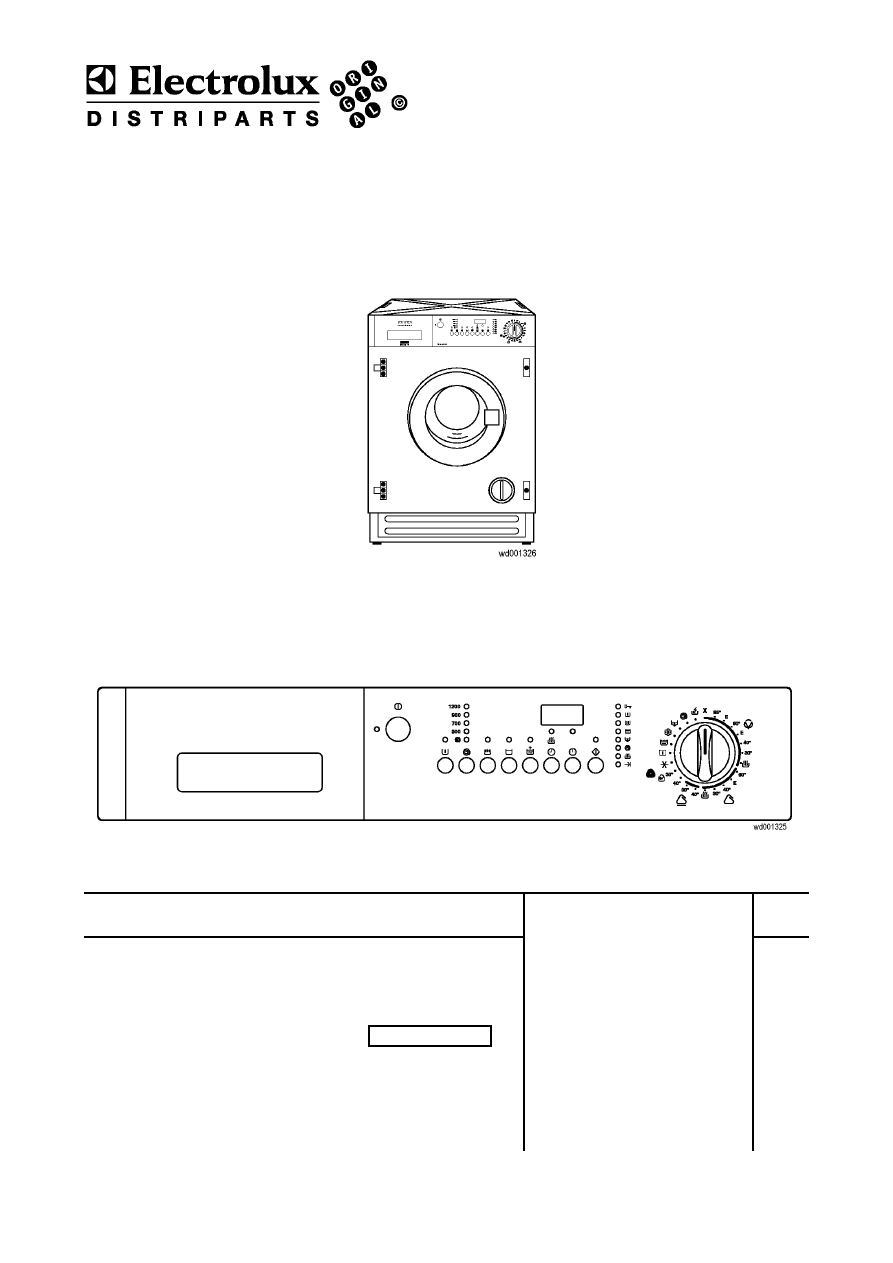
2 Control
panel
The control panel fitted to the appliance may be different depending on:
Ö
The control/display board
Ö
The different design of the panel
Ö
The different configuration of the buttons
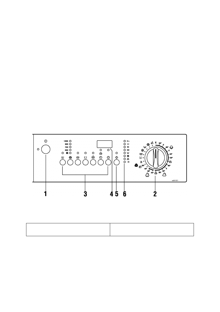
2.1 General
features
Programme selector:
- 24
positions
Push-buttons:
-
Maximum 8, horizontal position
LED:
-
Maximum 28, green for the wash functions, orange for the drying functions (washer dryers)
Display:
-
digits consisting of 24 green LEDs
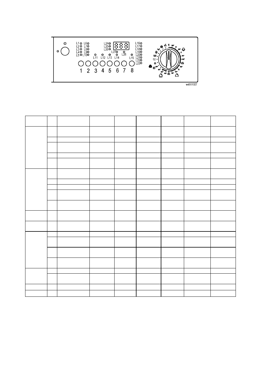
Example of control panel:
1. Switch
on/off
2. Programme
selector
3. Option
buttons
4. Display
5. Start/Pause
button
6. Programme
indicator
LEDs
SOI/DT 2002-06 eb
7
599 35 26-84
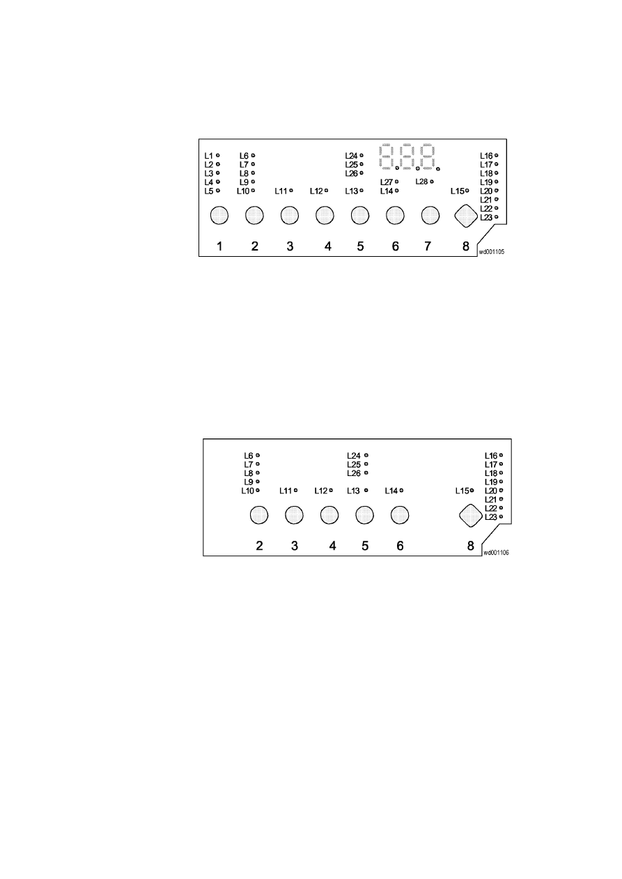
2.2 Control/Display
board
2.2.1 Version with display (washing machines and washer/dryers):
Ö
3 digits
Ö
28 LEDs
Ö
8 buttons
2.2.2 Version without display (washing machines)
Ö
21 LEDs
Ö
6 buttons
SOI/DT 2002-06 eb
8
599 35 26-84
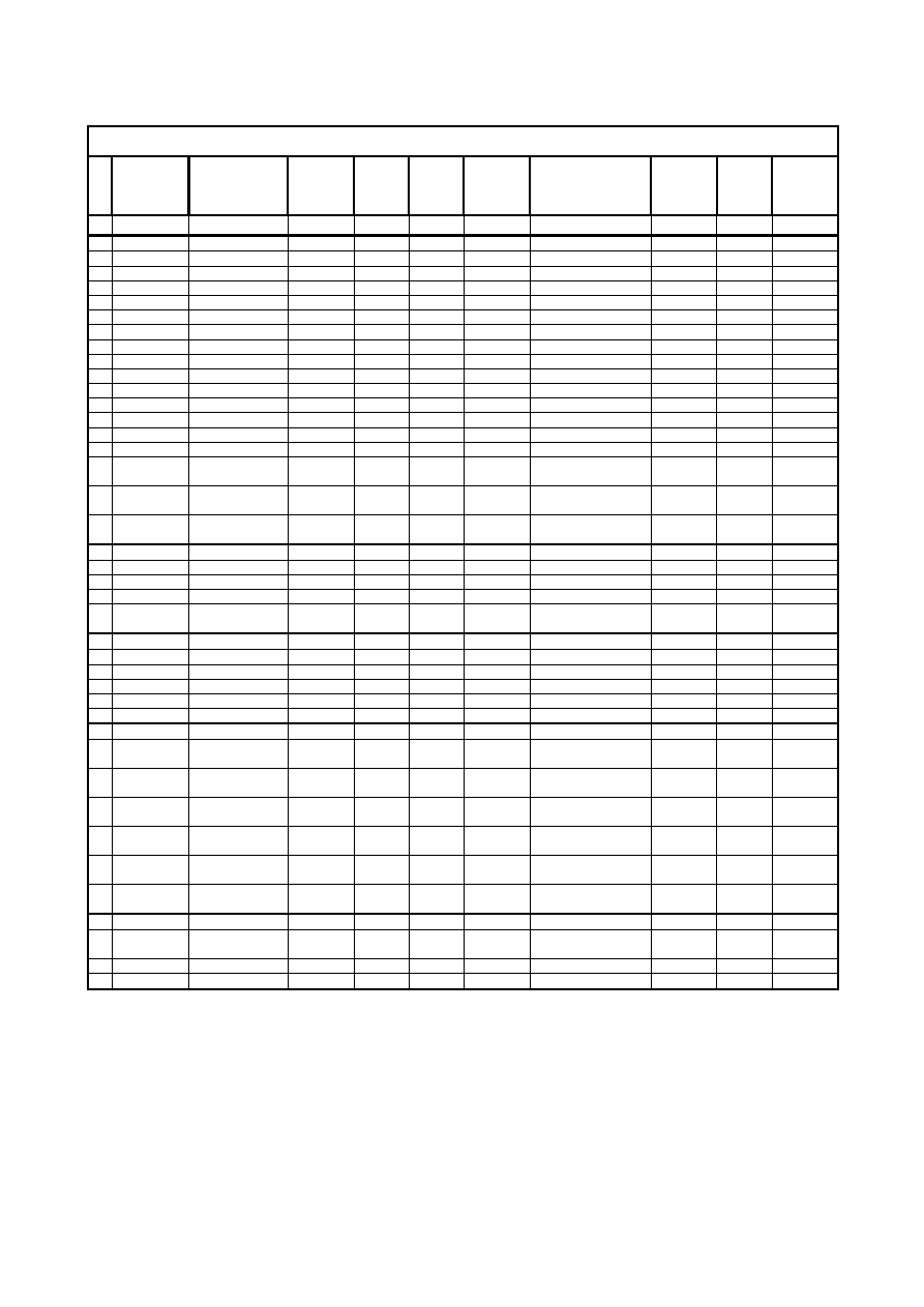
2.3 Washing
programmes
Washing programmes with 24 position selector knob- WM & WD -
No. Programme
Temperature
(°C)
No. of
rinses
Spin
1 Reset --
--
--
2 COTTON (WHITE)
90
°
3 IMPCF_01
3 COTTON ECO
67
°
3 IMPCF_01
4 COTTON (COLOUREDS)
60
°
3 IMPCF_01
5 COTTON 40AA or 60ECO
43
°
3 IMPCF_01
6 COTTON (COLOUREDS)
40
°
3 IMPCF_01
7 COTTON (COLOUREDS)
30
°
3 IMPCF_01
Cold wash (WM)
3
IMPCF_01
8 COTTON
Drying (washer-dryer)
--
--
9 SYNTHETICS
60
°
3 IMP5
10 SYNTHETICS 50 or ECONOMY
47
°
3 IMP5
11 SYNTHETICS
40
°
3 IMP5
12 SYNTHETICS (easy-iron)
30
°
3 IMP5
Cold wash (WM)
3
IMP5
13 SYNTHETICS
Drying (washer-dryer)
--
--
14 DELICATES
40
°
3 IMP7
15 DELICATES
30
°
3 IMP7
16 WOOL - HAND WASH
40
°
3 IMP4
17 WOOL - HAND WASH
30
°
3 IMP4
18 WOOL - HAND WASH
Cold
3
IMP4
19 SOAK 30°
--
--
RINSES (if spin >700: cotton rinses)
--
3
IMPCF_01
20
RINSES (if spin
≤
700: delicate rinses)
-- 3
IMP7
SOFTENER (if spin >700: cotton softener)
--
1
IMPCF_01
21
SOFTENER (if spin
≤
700: delicate softener)
-- 1
IMP7
22 DRAIN --
--
--
SPIN (if spin >700: cotton spin)
--
--
IMPCF_01
23
SPIN (if spin
≤
700: delicate spin)
-- --
IMP7
24 “MINI” PROGRAMME (30
°
/30min.)
30° 2
IMP7
See spin cycle chapter
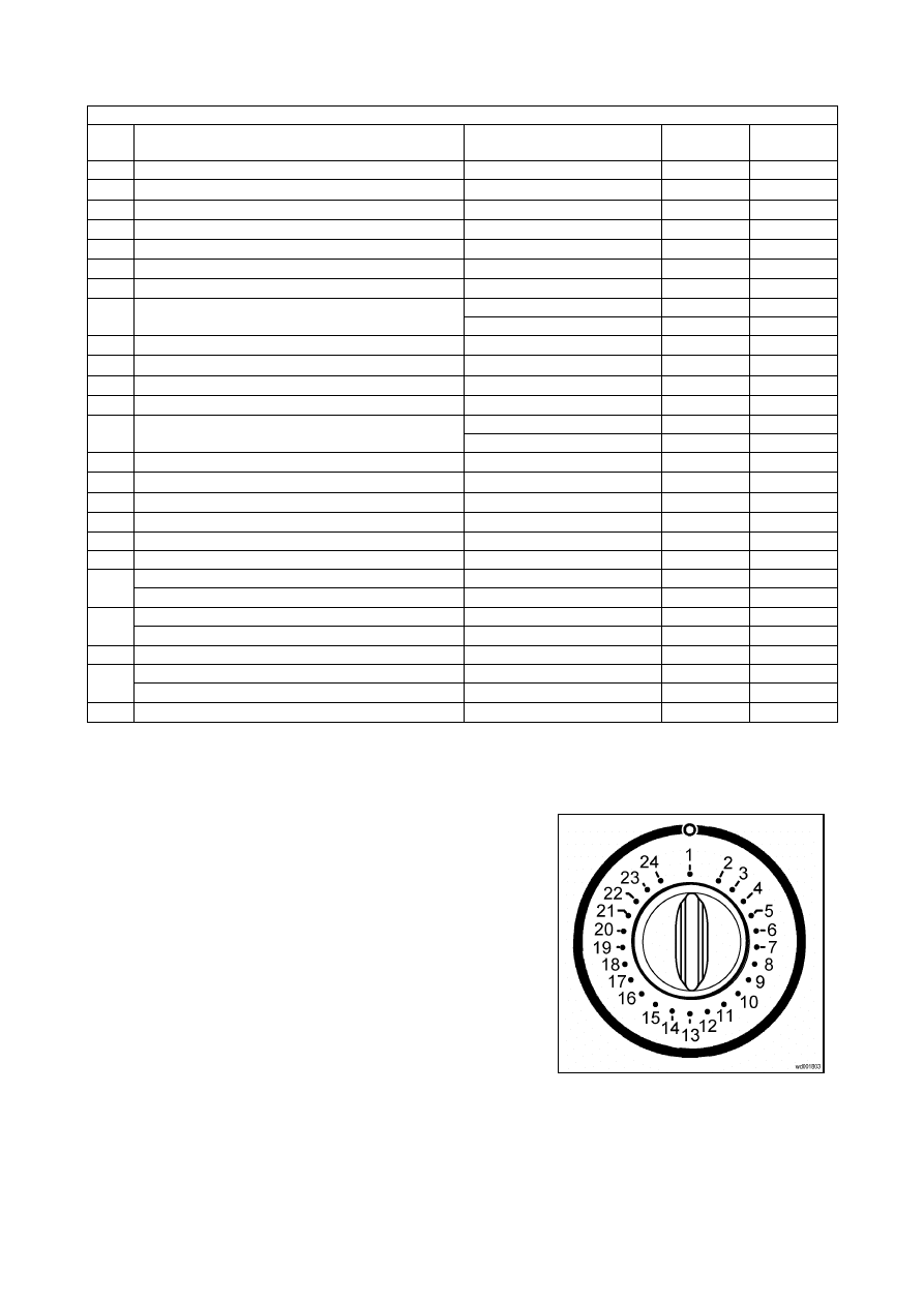
2.3.1 24-position selector knob
The programme selector determines the type of
washing cycle (for ex: water level, drum movement,
number of rinses), the washing temperature and
enables the drying cycle to be selected according to
the laundry.
The selector dial can be turned either clockwise or
anticlockwise.
The programme plate is divided into five sections:
Ö
Cotton (2
÷
8)
Ö
Synthetics (with the "easy iron" cycle - 9
÷
13)
Ö
Delicates (14
÷
15)
Ö
Wool – hand wash(16
÷
18)
Ö
Special cycles (19
÷
24)
The first position is used to cancel the current cycle.
SOI/DT 2002-06 eb
9
599 35 26-84
2.4 Push-button
function
The buttons’ function can be configured, and therefore it varies according to the model.
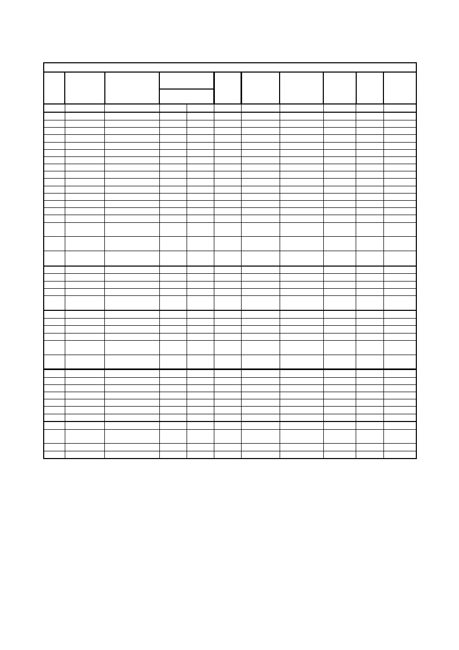
Matrix of the function of the different push-buttons:
Button LED Function 1
Function 2 Function
3
Function 4 Function 5 Function 6 Function 7
L1
Maximum
speed
Maximum
speed
90°C Very
heavy
90°C Intensive
--
L2
900 rpm
900 rpm
60°C
Heavy
60°C
Normal
--
L3
700 rpm
700 rpm
40°C
Normal
50°C
Short /
Very short
--
L4
500 rpm
500 rpm
30°C
Daily
40°C
--
--
1
L5
Night cycle /
Rinse hold
No spin Cold wash Light soil
30°C
--
Prewash
L6
Maximum
speed
Maximum
speed
90°C Very
heavy
90°C
--
--
L7
900 rpm
900 rpm
60°C
Heavy
60°C
--
--
L8
700 rpm
700 rpm
40°C
Normal
50°C
--
--
L9
500 rpm
500 rpm
30°C
Daily
40°C
Short /
Very short
--
2
L10 Night cycle /
Rinse hold
No spin Cold wash Light soil
30°C
Prewash
Prewash
3
L11 Night cycle /
Rinse hold
Spin speed
reduction
Intensive
Economy Stain
Short /
Very short
Prewash
4
L12 Night cycle /
Rinse hold
Spin speed
reduction
Intensive
Economy Stain
Short /
Very short
Extra/Super
rinse
L24
--
--
--
Intensive
Delay 8h
Extra Dry
--
L25
-- --
--
Normal
Delay
4h
Cupboard
Dry
--
L26
-- --
--
Short / Very
short
Delay 2h
Iron Dry
--
5
L13 Night cycle /
Rinse hold
Spin speed
reduction
Intensive
-- -- --
Extra/Super
rinse
L27
--
-- -- -- --
Drying
time
--
6
L14 Night cycle /
Rinse hold
Spin speed
reduction
Intensive
Bio Half
Load
--
Extra/Super
rinse
7
L28 Delayed
start
-- -- -- -- -- --
8
L15 Start/Pause
-- -- -- -- -- --
SOI/DT 2002-06 eb
10
599 35 26-84
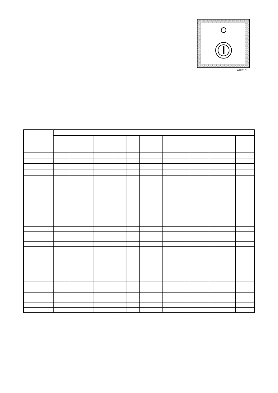
2.5 “ON/OFF” Button
By pushing this button the appliance switch on, by pushing it again the
appliance switch off.
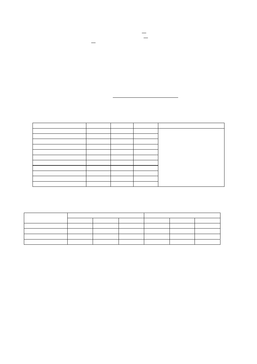
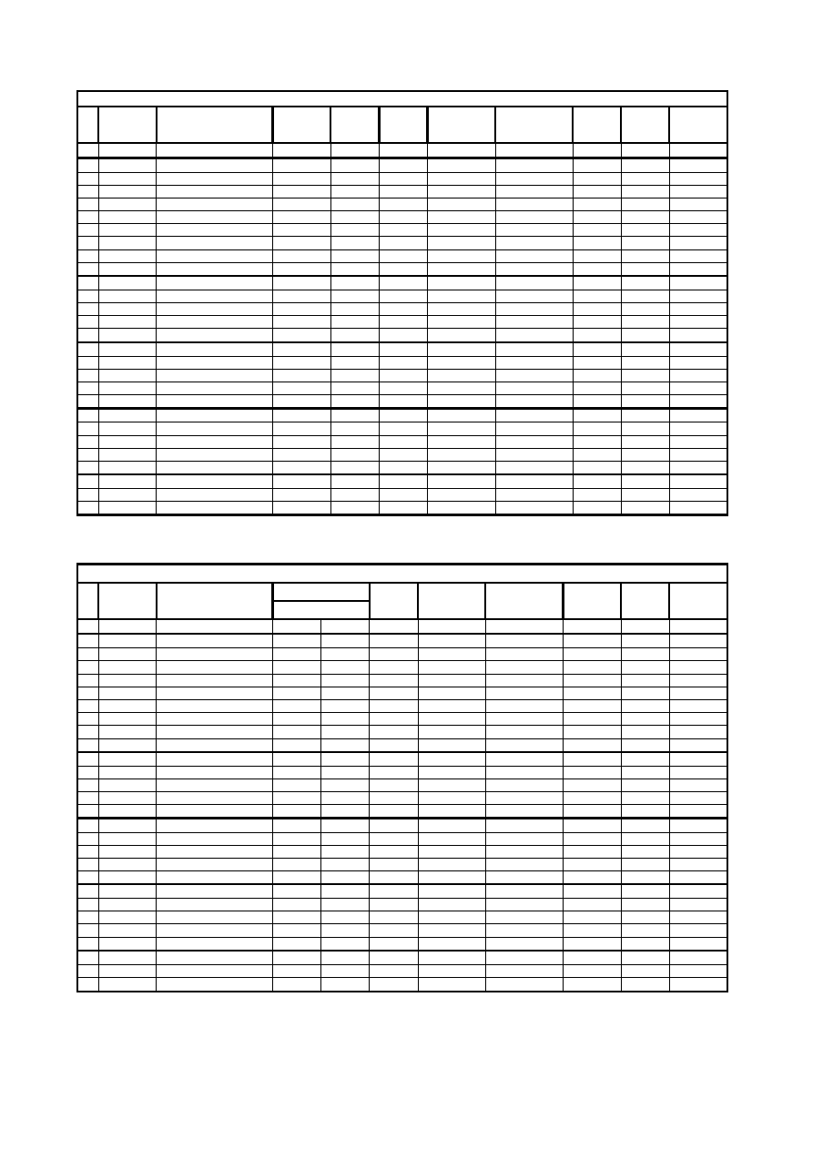
2.6 Washing cycle options
The washing cycle options should be entered after selecting the desired programme (using the selector
knob) and before pressing START/PAUSE.
When the button is pressed, the corresponding LED lights up; by pressing the button again the LED
switches off.
Possible options for each programme
Programmes
Options
Cotton Synthetics Delicate Wool Mini Soak Rinses
Softener
Spin Drain
95°C
⊗
Eco
X
60°C
X
⊗
X
50° o Eco
X
X
X
40°C
X X
⊗
⊗
X
30°C
X X X
X
⊗
Cold (WM)
X
X
X
X
X
Automatic
drying
3 levels
1 level
Time-controlled
drying
10
÷
130
minutes
10
÷
100
minutes
>900 rpm
⊗
X X X
900 rpm
X
⊗
⊗
X X X
700 rpm
X X
⊗
X
⊗
⊗
⊗
⊗
500 rpm
X
X X
X
X
X X X
No spin
X X
X
X
X X
Rinse hold /
Night cycle
X X X
X
X
X X
Prewash
X
X
X
Stains
X
X
X
Intensive
Very heavy
X
X
Daily
X
X
Short /
Very short/
Light
X
X
X
Economy
X
X
Bio
X
X
Extra / Super
rinse
X X X
X
Half load
X
Delayed start
X
X X
X
X
X X X X X
Legend:
⊗
= standard function X = option

SOI/DT 2002-06 eb
11
599 35 26-84
2.6.1 “Prewash”
button
This option selects an additional prewash phase at 30
°
C at the beginning of the cycle, followed first by a
drain phase and then by the next phase. In the COTTON and SYNTHETICS cycles also a short spin phase
is performed.
The prewash option cannot be selected for WOOL cycles, or in conjunction with the STAIN option.
2.6.2 “Stains”
button
The STAINS option can be selected in the COTTON, SYNTHETICS and DELICATES cycles with
temperatures of 40
°
C or higher. This option can be selected only during the programme selection phase,
before pressing the START/PAUSE button.
It is used with heavily soiled fabrics or stains; this option adds the STAIN phase, which consists of the
introduction of special additives from the prewash compartment after the BIO phase at 40ºC, as well as a
10-minute extension of the movement of the motor.
The STAINS option cannot be selected together with the PREWASH, INTENSIVE, and SHORT/VERY
SHORT/DAILY option.
2.6.3 “Intensive” / “Heavy soil” button
This option is available in the COTTON and SYNTHETICS cycles and it increases the duration of the
movement of the drum after the heating phases.
This option cannot be selected together with the STAINS, the QUICK /DAILY and the ECO options.
2.6.4 “Short”/ “Very short” button (“Light soil” / “Daily”)
This option can be selected in the COTTON, SYNTHETICS and DELICATES cycles, and can also be
selected while the appliance is in "PAUSE" mode. This option reduces the duration of the cycle.
In COTTON cycles, one of the rinses is eliminated; the water level in the other rinses is increased.
This option cannot be selected together with the STAINS, INTENSIVE or ECO options.
2.6.5 “Level of soiling” button
This option can be selected at any time during the washing programme (after pressing "PAUSE").
The standard programme is set for NORMAL soiling; by pressing this button; the user can modify this setting
to INTENSIVE/HEAVY SOIL or LIGHT SOIL/DAILY.
2.6.6 “BIO”
button
This option is available in the COTTON and SYNTHETICS cycles with temperatures equal to or higher than
40°C, and can be selected only during the programme selection phase.
The BIO option adds a 10-minute drum movement phase after the 40°C-heating phase in order to activate
the enzymes contained in the detergent.
2.6.7 “Half load” button
This option can be selected in the COTTON cycles on traditional (i.e. non-Jetsystem) washing machines,
and reduces the number of rinse cycles by one.
2.6.8 “Super rinse” or “Extra rinse” button
Can be used with all programmes except the wool programme. The machine performs 4 rinses instead
of 3.
This option is recommended for people who are allergic to detergents and in areas where the water is
very soft.
SOI/DT 2002-06 eb
12
599 35 26-84
2.6.9 “Rinse hold” or “Night cycle”
When this option is selected the cycle ends leaving water in the tub.
Ö
In the COTTON cycle it adds three rinses and eliminates all spins
Ö
In the SYNTHETICS cycles it adds a rinse and eliminates all spins
Ö
In all other cycles it eliminates all spins
During rinse hold phase, the final spin speed can be modified; press the START/PAUSE button to complete
the cycle, or select a new drain or spin programme. In this case turn the knob on the CANCEL position,
before the new programme is selected.
In case of washer-dryers, this option can not be selected, if the DRYING phase at the end of the cycle has
already been selected.
If the drain phase has not been performed after 18 hours, the programme ends automatically.
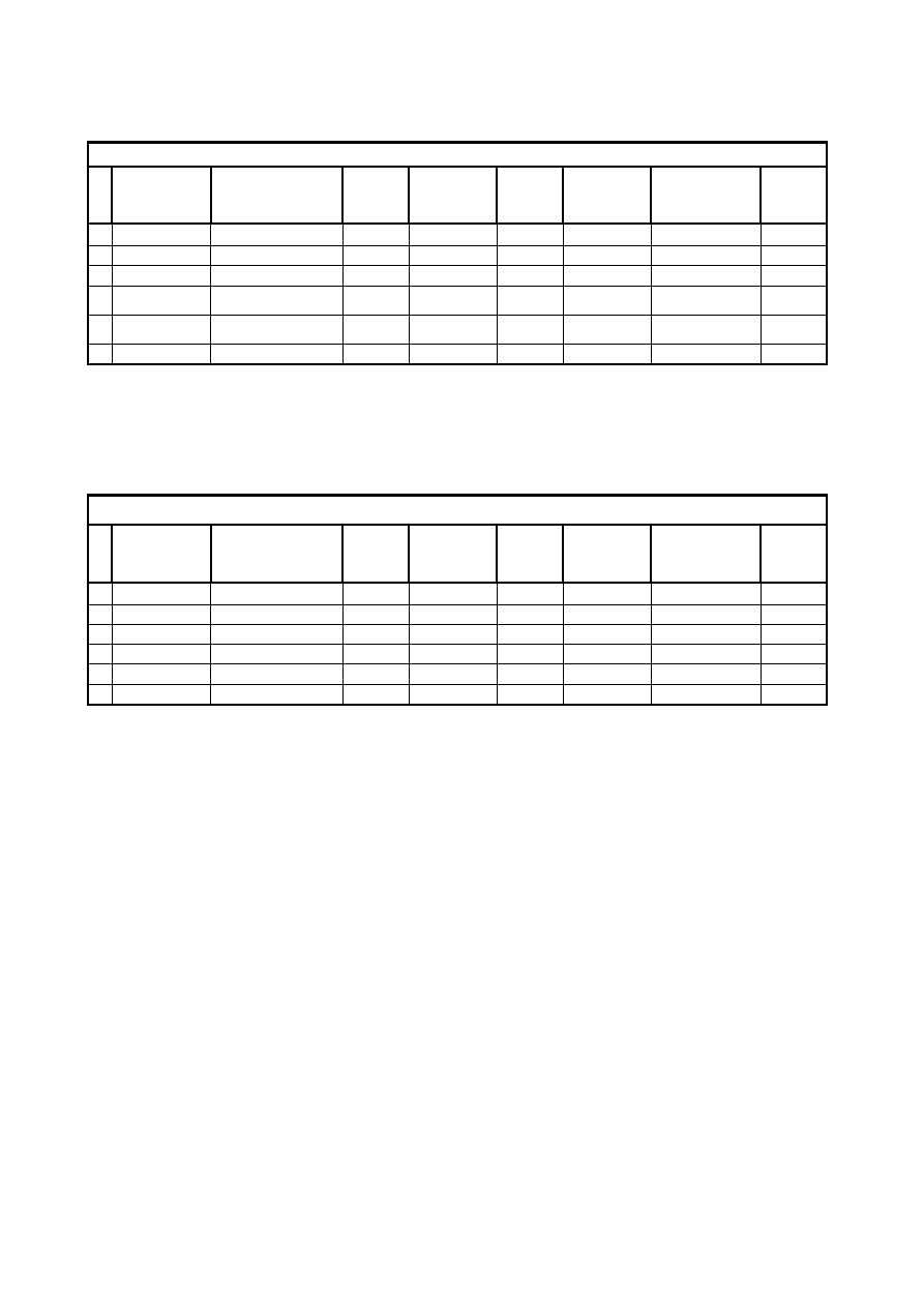
2.6.10 “Spin” button
When this button is pressed, the speed of the intermediate and final spin phases is modified as shown in the
table below. If automatic drying has already been selected (washer-dryers only), the minimum spin speed is
900 rpm for COTTON and 700 rpm for SYNTHETICS.
The configuration of this button varies according to the model:
Maximum speed
Level 1
Level 2
Level 3
Level 4
1600 washing machines
900 700 500
1600 washer-dryers
1200 900 700
1500 washing machines
900 700 500
1500 washer-dryers
1200 900 700
1400 washing machines
900 700 500
1400 washer-dryers
1200 900 700
1300
900 700 500
1200
900 700 500
1100
900 700 500
1000
900 700 500
900
--- 700 500
No spin
or
Rinse hold /
Night cycle
In COTTON cycles the “no spin” option is not available; moreover the structure of the rinsing
phases is modified according to the speed of the intermediate spin:
Traditional washing / Eco-ball
Jetsystem washing
Intermediate spin
(rpm)
1
st
rinse
2
nd
rinse
Last rinse
1
st
rinse
2
nd
rinse
Last rinse
<850
TR2 TR2 TR2 TR2 TR2 TR2
850
÷
950
TR1 TR2 TR2 TE TR2 TR2
1000
÷
1150
TR1 TR1 TR2 TE TE TR2
>1150
TR1 TR1 TR1 TE TE TE
TR2
Traditional rinse at second level
TR1
Traditional rinse at first level
TE
"total exchange" (virtual tank) jetsystem rinse
In the RINSE and SPIN special programmes, this button reduces not only the spin speed but it also modifies
the spin structure:
Ö
for spin phases higher than 700 rpm the spin cycle corresponds to the COTTON spin cycles
Ö
for spin phases equal or lower than 700 rpm the spin cycle corresponds to the DELICATES spin cycles
SOI/DT 2002-06 eb
13
599 35 26-84
2.6.11 “Reduced spin speed” button
When this button is pressed, the speed of the final spin in COTTON cycles is reduced to 650 rpm; in the
SYNTHETICS, DELICATES and WOOL cycles it is reduced to 500 rpm.
When the RINSE or SPIN cycles are selected, the spin structure changes from the COTTON to the
DELICATES spin.
2.7 "Delayed
start”
button
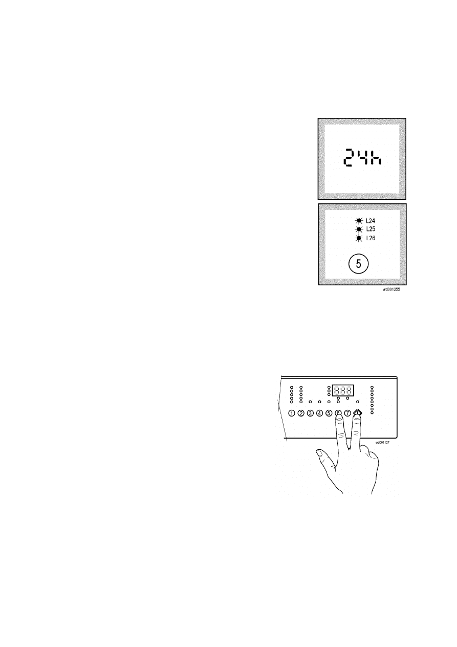
Models with digit: This button can be used during the programme
selection phase to enter a delayed start time (from 1 to 24 hours).
During the delayed start countdown, the time decreases at intervals of
one hour.
Models with led: This button can be used during the programme
selection phase to enter a delayed start time of 2, 4 or 8 hours. During
the delayed start countdown, the LEDs switch off according to the time
to elapse.
L24 Ö 8h
L25 Ö 4h
L26 Ö 2h
2.8 “No Buzzer” option
On models provided with buzzer, it is possible to
deactivate the sound, which indicates the end of the cycle.
Press simultaneously START/PAUSE button (8) and
no. 6 (or 5) button to deactivate the buzzer; this
option is memorised as long as it will not be
deactivated through the same procedure.
In case of an alarm condition the buzzer will be active.
SOI/DT 2002-06 eb
14
599 35 26-84
2.9 Options for washer-dryers
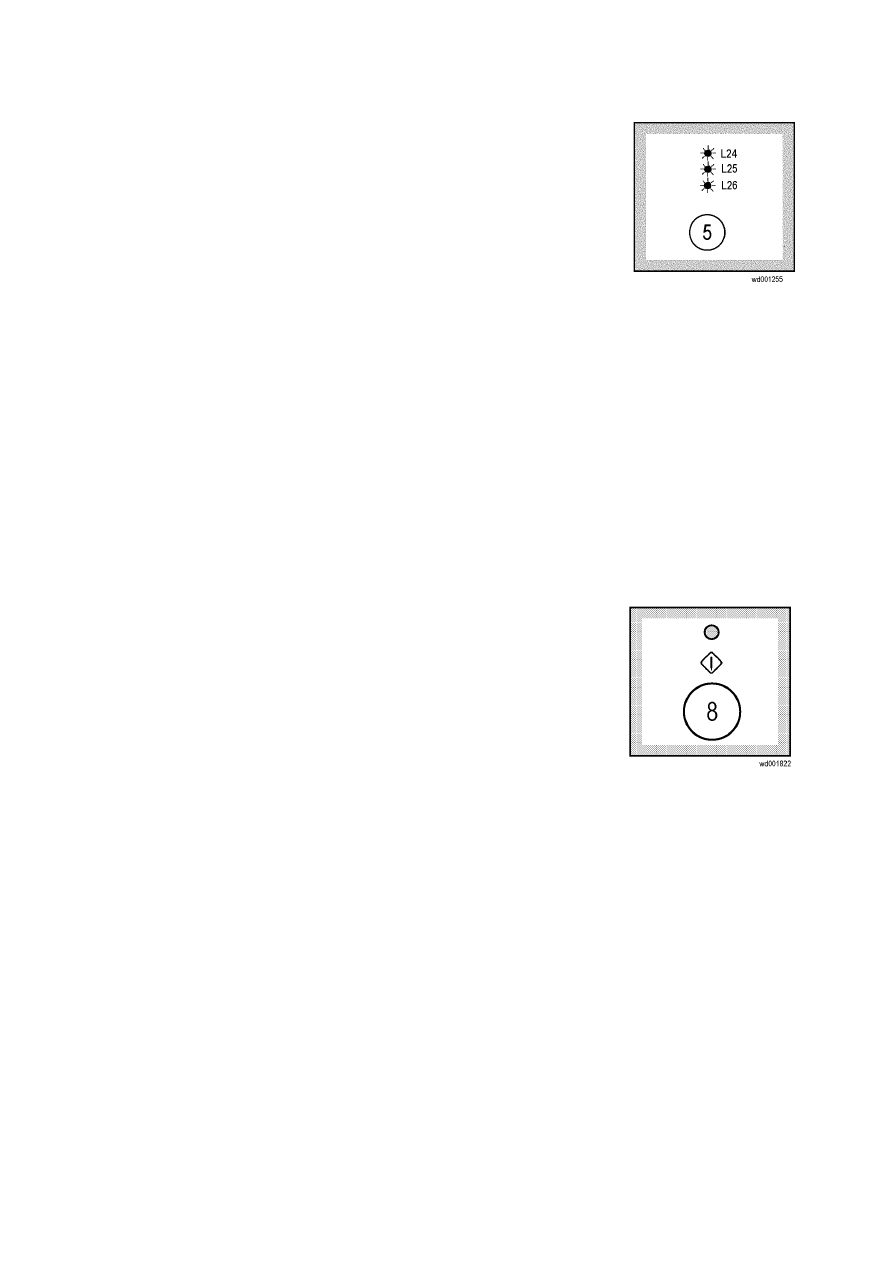
2.9.1 “Electronic drying” button
It is possible to select different electronic levels of dryness: three for
COTTON and one for SYNTHETICS cycles:
L24 Ö Extra dry (only cotton)
L25 Ö Store dry (cotton and synthetics)
L26 Ö Iron dry (only cotton)
The drying time is automatically calculated by the "Fuzzy" logic.
The drying phase can be performed either as automatic drying phase (non stop programme), if previously
selected together with the washing programme, as well as a separate drying phase.
2.9.2 “Drying time” button
When this button is pressed it is possible to select (5 minutes a time) from 10 to 130 minutes drying for
COTTON cycles and from 10 to 100 minutes for SYNTHETICS cycles.
The drying cycle can be selected both as automatic drying and as separate drying cycle.
2.10 “Start/Pause” button
Start: After entering the parameters for the cycle, press this button to
start the wash programme; the corresponding pilot light stops
flashing. If the DELAYED START button has been pressed, the
delayed start countdown is shown up in the display.
Pause: When the button is pressed again, the current programme is
interrupted and the display, or relative LED, flashes. When the
appliance is in “pause” mode the door can be opened provided
that:
- the appliance is not in the heating or drying phase
- the water level is not high
- there is no movement of the drum
When in “pause” mode, some of the programme parameters can be modified:
- all cycle options can be modified prior to the phase in which they are performed
- the spin speed can be modified before the final spin
- drying selections can be modified before the starting of the drying phase.
To re-start the cycle, press the START/PAUSE button.
Water drain and spin cycle: after the "rinse hold" phase, press this button to start the cycle with the drain
and final spin again.
SOI/DT 2002-06 eb
15
599 35 26-84
2.11 Display
The display shows the following information:
Ö
The wash programme duration; it is shown up after the programme has
been selected. The time corresponding to the maximum wash load is
shown up. While performing the cycle, the time decreases (updated)
every minute.
Ö
The drying programme duration (washer-dryers), which is displayed
during the phase of selection of the drying time. After two seconds the
total time corresponding to half wash load is shown up. In non-stop
cycles the time results from the wash plus drying time.
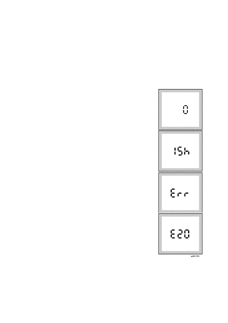
Ö
Rinse hold: the appliance stops with water in the tub at the end of
programmes for which the RINSE HOLD option has been selected; the
display shows a zero (fixed, not flashing).
Ö
The programme end indicated by a "0" flashing (when it is possible to
open the door).
Ö
The delayed start, selected through the relative button. After the
START/PAUSE button has been pressed, the countdown begins and
the time decreases every hour.
Ö
An incorrect option selection is signalled by Err on the display if the
function selected is not compatible with the programme.
Ö
An alarm code, in case of a malfunction.
SOI/DT 2002-06 eb
16
599 35 26-84
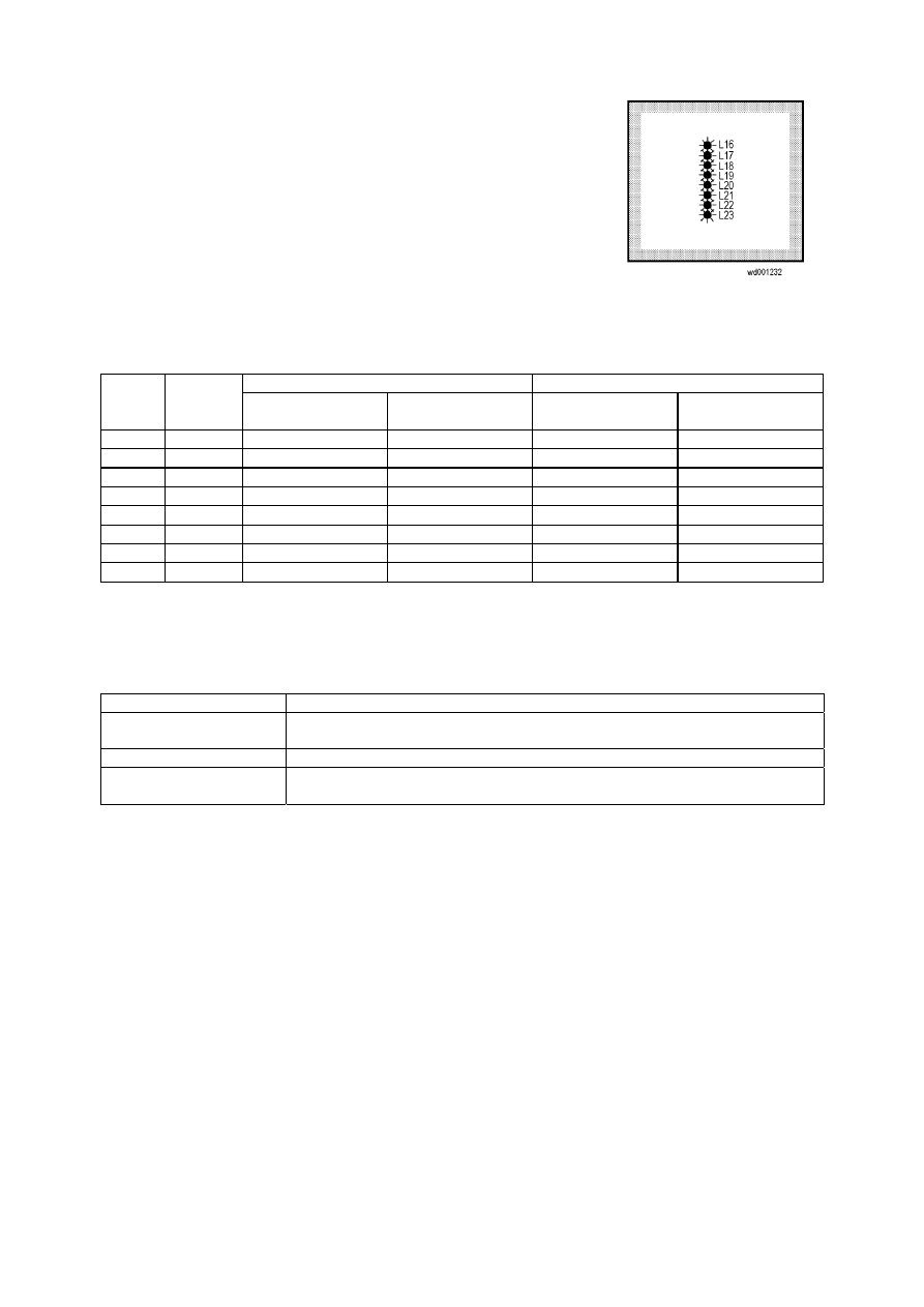
2.12 Programme phase Leds
During the selection of the programme, the LEDs relative
to the different phases of the programme light up.
When the cycle starts only the LED corresponding to the
current phase lights.
The programme end LED switches on when the
programme ends.
The "overdosing" LED switches on at the end of the cycle if, during the
programme, foam is detected caused by an excessive detergent addition
(in some cases the cause might be an obstructed drain hose).
LED function according to the type of appliance:
Without door indication LED
With door indication LED
LED
LED
colour
Washing
machines
Washer-dryers Washing
machines
Washer-dryers
L16
Green Prewash
Prewash
Door
Door
L17
Green Wash
Wash
Prewash Prewash
L18
Green
Rinse Rinse Wash Wash
L19
Green
Rinse Hold
Rinse Hold
Rinse
Rinse
L20
Green
Drain Drain Drain Drain
L21
Green
Spin Spin Spin Spin
L22
Orange
Filter Clogged
Drying
Filter Clogged
Drying
L23
Green End/alarm
End
End/alarm
End
Door LED
The following table shows the door LED the function:
LED status
Meaning
On
While the cycle is performing with the possibility to open the door (in pause
mode)
Flashing
Cycle in pause mode without the possibility to open the door (closed door)
Off
While the cycle is performing without the possibility to open the door (in
pause mode) or door open
SOI/DT 2002-06 eb
17
599 35 26-84
3 Washing programmes (sequence charts)
Key to programmes
Description
Calibration
Drain sub-phase for calibration of the electronic pressure switch
Levels
mm H
2
O
Level expressed in water mm (full/empty)
Pumps
OFF
Pump off
ON
Pump on
LEV
Pump on from one level of pressure switch
Water inlet valves
ELV2
Prewash
ELV3
Wash
ELV2 ELV3
Prewash + wash = softener
Refilling
NR
Normal refilling
VT
"Total exchange" refilling (virtual tank)
Dis
Refilling disabled
Time
‘
Minutes
“
Seconds
Tout
Max. time (timeout)
Drying
TMP
It is active up to the selected temperature
Motor movement
Code
Pause(sec)
Movement(sec)
Speed (rpm.)
D_MOV
12 4 55
E_MOV
5 8 55
E1_MOV
4 12 75
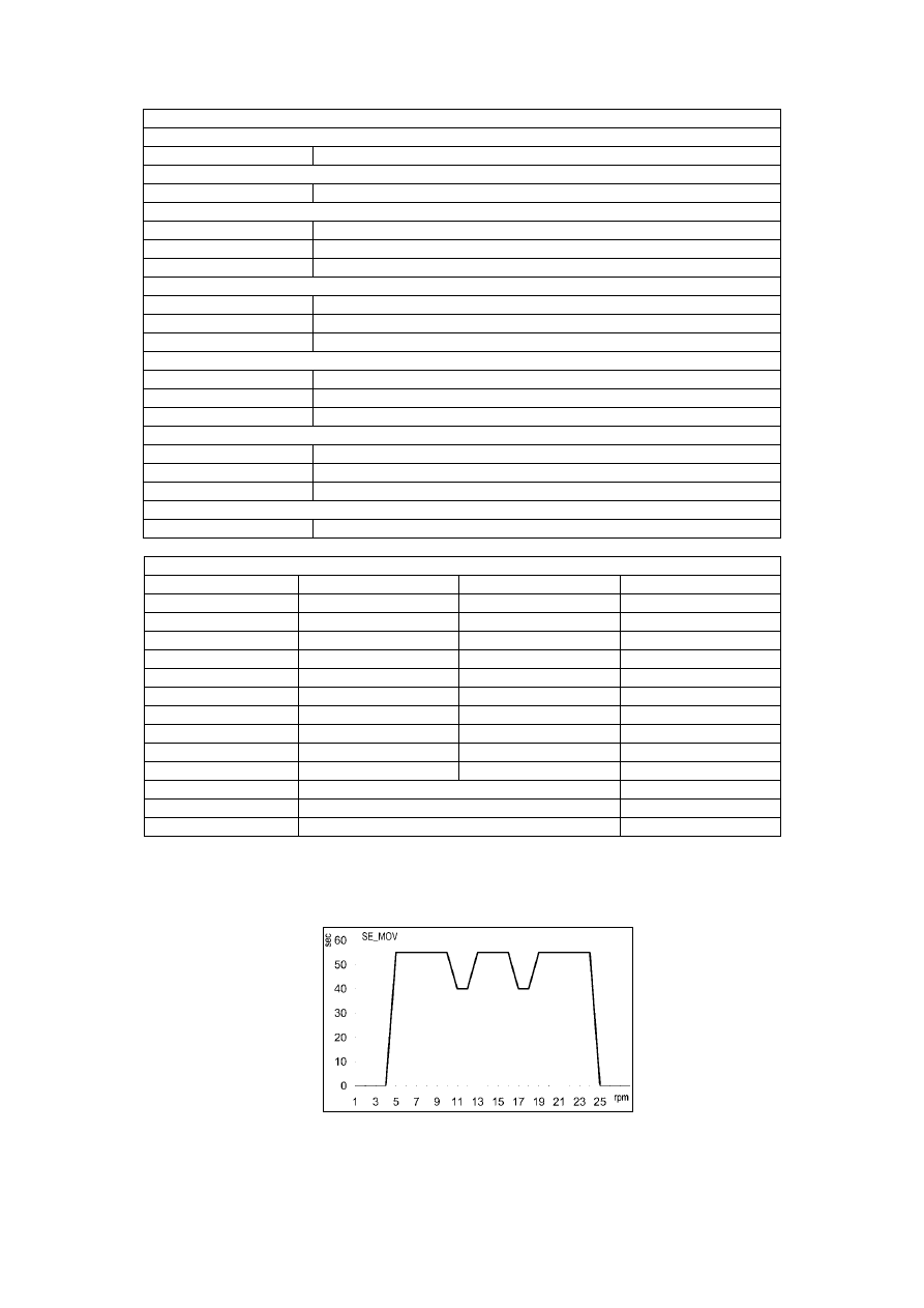
SE_MOV
4 21
55/40
N_MOV
8 8 55
PWL1_MOV
40 1 35
PWL3_MOV
12 1 35
PWL4_MOV
57 1 35
COLD_MOV
4 12 40
DRY_MOV
57 3 55
CR3_MOV
Unidirectional movement
80
DLD_MOV
Unidirectional movement
40
OFF
No movement
0
SE_MOV Mov:
SOI/DT 2002-06 eb
18
599 35 26-84
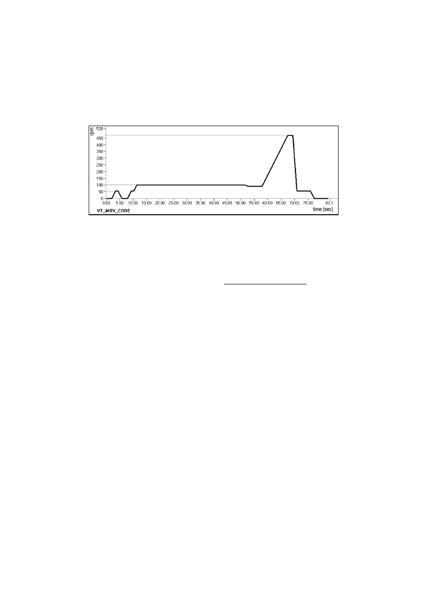
VT movement during rinses in "jetsystem total exchange" COTTON programmes – Only for models
with circulation pump (jetsystem):
During these phases, in which the motor rotates at high speed, if the electronic pressure switch detects that
the water in the tub falls below a certain level, the following operations are performed:
Ö
spin at 470 rpm (VT_MOV_CODE) to remove the water from the fabrics and therefore to increase the
level in the tub
Ö
5 seconds pause, during which the level is again checked and, if necessary, the solenoid valve is
activated in order to load water until the level is correct
Ö
energetic movement (E) (with the circulation pump in operation)
These operations may be repeated up to a maximum of three times for each rinse.
The parameters of the different programmes (levels, movements) vary according to the wash system
of the different models:
⇒ jetsystem (with circulation pump)
⇒ traditional
SOI/DT 2002-06 eb
19
599 35 26-84
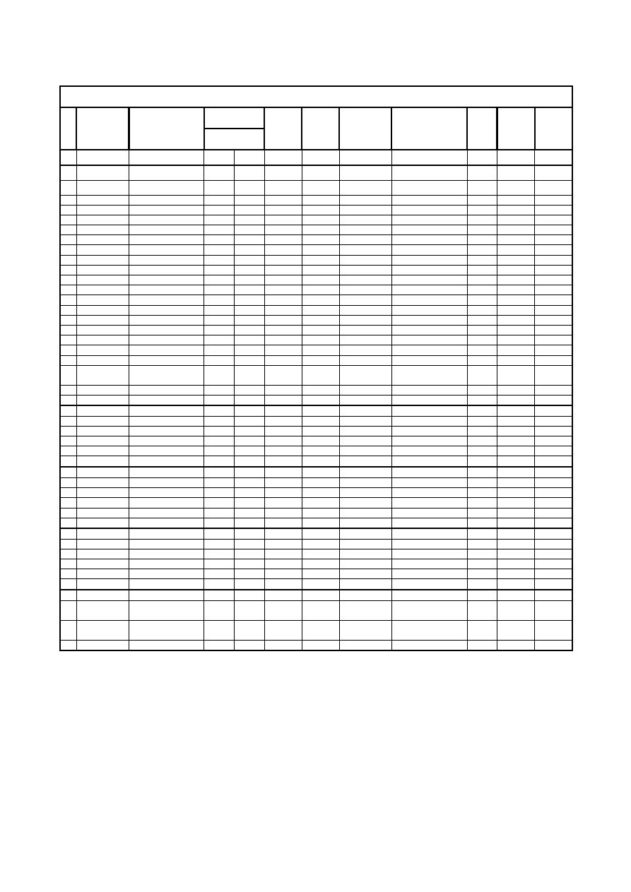
3.1 Cotton
60
°
C (Jetsystem)
(W2C01450) Cotton 60 JETSYSTEM Intermediate spin 850-1000
Levels
N.
Phase
Description
(mm H
2
O)
Rec.
pump
Drain
pump
Elv / Det
comp.
Movement
Re-
filling
Temp.
°C
Time
0
CALIBRATION
35/15 OFF ON
OFF
Dis Tout
10'
1
Washing
WATER FILL
40/15
OFF
OFF
ELV2
OFF
NR
Tout 15'
2 MOVEMENT
40/15
OFF
OFF
ELV2
PWL3_MOV
NR
1'
3
WATER FILL
85/55
OFF
OFF
ELV3
OFF
NR
Tout 15'
4 MOVEMENT
85/55
OFF
OFF
ELV3
COLD_MOV
NR
5'
5 MOVEMENT
ON
OFF
E_MOV Dis
1'
6 MOVEMENT
OFF
OFF
E_MOV Dis
22''
7 MOVEMENT
70/55
OFF
OFF
ELV3
E_MOV NR
2'
8 MOVEMENT
ON
OFF
E_MOV Dis
2'
9 HEATING+MOV.
ON
OFF
E_MOV Dis
40 2'
10
HEATING
35/15
ON
OFF
ELV3
E_MOV
NR
40
Tout 40'
11 HEATING+MOV.
ON
OFF
E_MOV Dis
54 2'
12
HEATING
35/15
OFF
OFF
ELV3
E_MOV
NR
54
Tout 40'
13 MOVEMENT ON
OFF
E_MOV Dis 2'
14 HEATING+MOV.
OFF
OFF
E_MOV Dis
54 2'
15
HEATING
35/15
OFF
OFF
ELV3
E_MOV
NR
54
Tout 40'
16
MOVEMENT ON
OFF
SE_MOV Dis 12'
17 MOVEMENT ON
OFF
N_MOV Dis 4'
18
MOVEMENT ON
OFF
SE_MOV Dis 14'
19 WATER
DRAIN
OFF
Lev
OFF Dis
Tout
10'
20
TIME WATER
DRAIN
OFF
ON
OFF Dis 30''
21
SPINNING
OFF
ON INP6_INP_SECT
Dis
Tout
20'
22
SPINNING
OFF
ON INP6_SP_SECT
Dis
Tout
20'
23
1
st
Rinse
MOVEMENT OFF
OFF
CR3_MOV Dis 5''
24
WATER FILL
75/20
LEV
OFF
ELV3
CR3_MOV
VT
Tout 15'
25 MOVEMENT
35/25
ON
OFF ELV3
E_MOV NR 5'
26 MOVEMENT ON
OFF
E1_MOV Dis 3'
27 WATER
DRAIN
OFF
Lev
D_MOV Dis
Tout
10'
28
SPINNING
OFF
ON IMP6_RINSE
Dis
Tout
20'
29
2
nd
Rinse
MOVEMENT OFF
OFF
CR3_MOV Dis 5''
30
WATER FILL
75/20
LEV
OFF
ELV3
CR3_MOV
NR
Tout 15'
31 MOVEMENT
35/25
ON
OFF
E_MOV VT 5'
32 MOVEMENT ON
OFF
E1_MOV Dis 3'
33 WATER
DRAIN
OFF
Lev
D_MOV Dis
Tout
10'
34
SPINNING
OFF
ON IMP6_RINSE
Dis
Tout
20'
35
3
rd
Rinse
MOVEMENT OFF
OFF
CR3_MOV Dis 5''
36 (softener)
WATER FILL
75/20
LEV
OFF
ELV2 ELV3
OFF
NR
Tout 15'
37 MOVEMENT
75/20
LEV
OFF
ELV2
ELV3 N_MOV NR 30''
38 MOVEMENT
75/20
LEV
OFF
ELV2
ELV3 OFF NR 5''
39
WATER FILL
95/20
LEV
OFF
ELV2 ELV3
N_MOV
NR
Tout 15'
40 MOVEMENT
95/20
LEV
OFF
ELV2
ELV3 N_MOV NR 11'
41
Spinning
WATER DRAIN
OFF
Lev
OFF
Dis
Tout 10'
42
TIME WATER
DRAIN
OFF
ON
OFF Dis 15''
43
SPINNING
OFF
ON
IMPCF_01_(AC-
DC)
Dis Tout
20'
44
MOVEMENT
OFF
OFF
N_MOV Dis 2'
SOI/DT 2002-06 eb
20
599 35 26-84
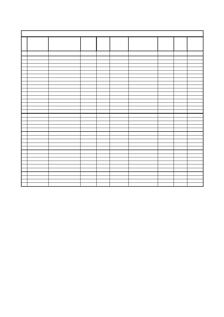
3.2 Cotton
60
°
C (Traditional/Eco-ball)
(W2C01450) Cotton 60 TRADITIONAL / ECO BALL Intermediate spin 850 1000
N.
Phase
Description
Levels
(mm H
2
O)
Drain
pump
Elv / Det
comp.
Movement
Refilling Temp.
°C
Time
0
CALIBRATION 40/15 ON
OFF Dis
Tout 10’
1
Washing
WATER FILL
40/15
OFF
ELV2
OFF
NR
Tout 15'
2
MOVEMENT 40/15
OFF
ELV2
PWL3_MOV NR 1'
3
WATER FILL
95/57
OFF
ELV3
OFF
NR
Tout 15'
4
MOVEMENT 75/55
OFF
ELV3
COLD_MOV NR 5'
5
MOVEMENT 75/55
OFF
ELV3
E_MOV NR 2'
6
HEATING
75/55
OFF
ELV3
E_MOV
NR
40
Tout 40'
7
HEATING
75/55
OFF
ELV3
E_MOV
NR
54
Tout 40'
8
MOVEMENT
OFF
E_MOV Dis
2'
9
HEATING
75/55
OFF
ELV3
E_MOV
NR
54
Tout 40'
10
MOVEMENT
OFF
E_MOV Dis
10'
11
MOVEMENT OFF
N_MOV Dis 4'
12
MOVEMENT
OFF
E_MOV Dis
24'
13
WATER DRAIN
Lev
OFF
Dis
Tout 10'
14 TIME
WATER
DRAIN
ON
OFF
Dis 30''
15
SPINNING
ON INP6_INP_SECT
Dis
Tout
20'
16
SPINNING
ON INP6_SP_SECT
Dis
Tout
20'
17
1
st
Rinse
MOVEMENT
OFF
OFF Dis
5''
18
WATER FILL
100/65
OFF
ELV3
OFF
NR
Tout 15'
19
MOVEMENT 100/65
OFF
ELV3
E_MOV NR 6'
20
WATER DRAIN
Lev
D_MOV
Dis
Tout 10'
21
SPINNING
ON IMP6_RINSE Dis
Tout
20'
22
2
nd
Rinse
MOVEMENT
OFF
OFF Dis
5''
23
WATER FILL
100/65
OFF
ELV3
OFF
NR
Tout 15'
24
MOVEMENT
OFF
ELV3
E_MOV NR
6'
25
WATER DRAIN
Lev
D_MOV
Dis
Tout 10'
26
SPINNING
ON IMP6_RINSE Dis
Tout
20'
27
3
rd
Rinse
MOVEMENT
OFF
OFF Dis
5''
28
(softener)
WATER FILL
100/65
OFF
ELV2 ELV3
OFF
NR
Tout 15'
29
MOVEMENT
100/65
OFF
ELV2
ELV3 N_MOV NR 30''
30
MOVEMENT
100/65
OFF
ELV2
ELV3 OFF
NR 5''
31
WATER FILL
140/95
OFF
ELV2 ELV3
OFF
NR
Tout 15'
32
MOVEMENT
OFF
ELV2
ELV3
E_MOV NR
7'
33
Spinning
WATER DRAIN
Lev
OFF
Dis
Tout 10'
34 TIME
WATER
DRAIN
ON
OFF
Dis 15''
35
SPINNING
ON
IMPCF_01_(AC-DC)
Dis
Tout
20'
36
MOVEMENT OFF
N_MOV Dis 2'
SOI/DT 2002-06 eb
21
599 35 26-84
3.3 Synthetics
40
°
C (Jetsystem)
(W2C01450) Synthetics 40 JETSYSTEM
N.
Phase
Description
Levels
(mm H
2
O)
Rec.
pump
Drain
pump
Elv / Det
comp.
Movement
Refilling Temp.
°C
Time
0 CALIBRATION
35/15
OFF
ON
OFF Dis
Tout
10'
1
Washing
WATER FILL
40/15
OFF
OFF
ELV2
OFF
NR
Tout 15'
2 MOVEMENT
40/15
OFF
OFF
ELV2
PWL3_MOV NR 1'
3
WATER FILL
100/65
LEV
OFF
ELV3
OFF
NR
Tout 15'
4 MOVEMENT
100/65
LEV
OFF
ELV3
N_MOV
NR 7'
5
HEATING
100/65
ON
OFF
ELV3
N_MOV
NR
38
Tout 40'
6 MOVEMENT
100/65
LEV
OFF
ELV3
N_MOV
NR 8'
7
HEATING
100/65
ON
OFF
ELV3
E_MOV
NR
40
Tout 40'
8 MOVEMENT
100/65
LEV
OFF
ELV3
D_MOV
NR 3'
9 MOVEMENT
100/65
LEV
OFF
ELV3
E_MOV
NR 7'
10 HEAT+MOV
100/65
ON
OFF
ELV3
D_MOV
NR 40 3'
11 MOVEMENT
100/65
LEV
OFF
ELV3
E_MOV
NR 6'
12
WATER FILL
160/80
LEV
OFF
ELV3
N_MOV
NR
Tout 1'
13 MOVEMENT LEV
OFF
N_MOV
Dis 1'
14 MOVEMENT LEV
OFF
N_MOV
Dis 1'
15
WATER DRAIN
OFF
Lev
OFF
Dis
Tout 10'
16
TIME WATER
DRAIN
OFF
ON
OFF
Dis 30''
17
TIME WATER
DRAIN
OFF
ON
E_MOV Dis 30''
18
TIME WATER
DRAIN
OFF
ON
E_MOV
Dis 1'
19
1
st
Rinse
MOVEMENT OFF
OFF
OFF
Dis 5''
20
WATER FILL
160/80
LEV
OFF
ELV3
OFF
NR
Tout 15'
21 MOVEMENT
160/80
LEV
OFF
ELV3
N_MOV
NR 2'
22
WATER DRAIN
LEV
Lev
E_MOV
Dis
Tout 10'
23
TIME WATER
DRAIN
LEV
ON
E_MOV
Dis 2'
24
2
nd
Rinse
MOVEMENT LEV
OFF
OFF
Dis 5''
25
WATER FILL
160/80
LEV
OFF
ELV3
OFF
NR
Tout 15'
26 MOVEMENT
160/80
LEV
OFF
ELV3
N_MOV
NR 2'
27
WATER DRAIN
OFF
Lev
E_MOV
Dis
Tout 10'
28
SPINNING OFF
ON IMP_C0_INP_SECT
Dis Tout
20'
29
SPINNING OFF
ON IMP_C0_SP_SECT
Dis Tout
20'
30
3
rd
Rinse
MOVEMENT OFF
OFF
OFF
Dis 5''
31 (softener)
WATER FILL
100/65
OFF
OFF
ELV2
ELV3
OFF NR
Tout
15'
32 MOVEMENT OFF
OFF
ELV2
ELV3
N_MOV NR 30''
33 MOVEMENT OFF
OFF
ELV2
ELV3
OFF NR
5''
34 WATER
FILL
160/80
LEV
OFF
ELV2
ELV3
OFF NR
Tout
15'
35 MOVEMENT
160/80
LEV
OFF
ELV2
ELV3
N_MOV NR
2'
36 MOVEMENT
160/80
LEV
OFF
ELV2
ELV3
N_MOV NR
3'
37
Spinning
WATER DRAIN
OFF
Lev
OFF
Dis
Tout 10'
38
TIME WATER
DRAIN
OFF
ON
OFF
Dis 15''
39 SPINNING OFF
OFF
IMP5
Dis
Tout
20'
40 MOVEMENT OFF
OFF
N_MOV
Dis 1'
SOI/DT 2002-06 eb
22
599 35 26-84
3.4 Synthetics
40
°
C (Traditional/Eco-ball)
(W2C01450) Synthetics 40 ECOBALL-TRADITIONAL
Levels
(mm H
2
O)
N.
Phase
Description
(mm H
2
O)
Drain
pump
Elv / Det
comp.
Movement Refilling
Temp.
°C
Time
0 CALIBRATION
40/15
ON OFF Dis
Tout
10'
1
Spinning
WATER FILL
40/15
OFF
ELV2
OFF
NR
Tout 15'
2 MOVEMENT
40/15
OFF
ELV2
PWL3_MOV
NR
1'
3
WATER FILL
120/90
OFF
ELV3
OFF
NR
Tout 15'
4 MOVEMENT
120/90
OFF
ELV3
N_MOV
NR
7'
5
HEATING
120/90
OFF
ELV3
N_MOV
NR
40
Tout 40'
6 MOVEMENT
120/90
OFF
ELV3
N_MOV
NR
8'
7
HEATING
120/90
OFF
ELV3
E_MOV
NR
40
Tout 40'
8 MOVEMENT
120/90
OFF
ELV3
D_MOV
NR
3'
9 MOVEMENT
120/90
OFF
ELV3
E_MOV NR 7'
10 HEAT+MOV
120/90
OFF
ELV3
D_MOV
NR
40 3'
11 MOVEMENT
120/90
OFF
ELV3
E_MOV NR 6'
12
WATER FILL
155/10
OFF
ELV3
N_MOV
NR
Tout 1'
13 MOVEMENT
OFF N_MOV
Dis 1'
14 MOVEMENT
OFF N_MOV
Dis 1'
15 WATER
DRAIN
Lev
OFF Dis
Tout
10'
16
TIME WATER
DRAIN
ON
OFF Dis 30''
17
TIME WATER
DRAIN
ON E_MOV Dis 30''
18
TIME WATER
DRAIN
ON E_MOV
Dis 1'
19
1
st
Rinse
MOVEMENT OFF
OFF Dis 5''
20
WATER FILL
155/10
OFF
ELV3
OFF
NR
Tout 15'
21 MOVEMENT
155/10
OFF
ELV3
N_MOV
NR 2'
22 WATER
DRAIN
Lev E_MOV
Dis
Tout
10'
23
TIME WATER
DRAIN
ON E_MOV
Dis 2'
24
2
nd
Rinse
MOVEMENT OFF
OFF Dis 5''
25
WATER FILL
155/10
OFF
ELV3
OFF
NR
Tout 15'
26 MOVEMENT
155/10
OFF
ELV3
N_MOV
NR 2'
27 WATER
DRAIN
Lev E_MOV
Dis
Tout
10'
28 SPINNING
ON
IMP_C0_INP_
SECT
Dis
Tout
20'
29 SPINNING
ON
IMP_C0_SP_
SECT
Dis
Tout
20'
30
3
rd
Rinse
MOVEMENT OFF
OFF Dis 5''
31
(softener)
WATER FILL
120/90
OFF
ELV2 ELV3
OFF
NR
Tout 15'
32 MOVEMENT
120/90
OFF
ELV2
ELV3
N_MOV NR 30''
33 MOVEMENT
120/90
OFF
ELV2
ELV3
OFF NR 5''
34
WATER FILL
155/10
OFF
ELV2 ELV3
OFF
NR
Tout 15'
35 MOVEMENT
155/10
OFF
ELV2
ELV3
N_MOV
NR 2'
36 MOVEMENT
155/10
OFF
ELV2
ELV3
N_MOV
NR 3'
37
Spinning
WATER
DRAIN
Lev
OFF Dis
Tout
10'
38
TIME WATER
DRAIN
ON
OFF Dis 15''
39 SPINNING
ON IMP5 Dis
Tout
20'
40 MOVEMENT
OFF N_MOV
Dis 1'
SOI/DT 2002-06 eb
23
599 35 26-84
3.5 Hand wash 30º (Jetsystem)
(W2C01450) Handwash 30 JETSYSTEM
N. Phase
Description
Levels
(mm H
2
O)
Rec.
pump
Drain
pump
Elv / Det
comp.
Movement
Refillin
g
Temp.
°C
Time
0
CALIBRATION 35/15
OFF
ON
OFF Dis Tout
10'
1 Washing
WATER FILL
40/15
OFF
OFF
ELV2
OFF
NR
Tout 15'
2
MOVEMENT 40/15
OFF
OFF ELV2
PWL3_MOV
NR
1'
3
WATER FILL
115/50
LEV
OFF
ELV3
OFF
NR
Tout 15'
4
MOVEMENT 115/50
LEV
OFF ELV3
PWL4_MOV
NR
4'
5
HEATING
115/50 ON OFF ELV3
PWL4_MOV NR 30 Tout
40'
6
MOVEMENT 115/50
LEV
OFF ELV3
PWL4_MOV
NR
2'
7
HEAT+MOV 115/50
LEV
OFF
ELV3
PWL4_MOV
NR
30 14'
8
WATER
DRAIN
OFF
Lev
OFF Dis
Tout
10'
9 TIME
WATER
DRAIN OFF
ON
OFF Dis
1'
10 1
st
Rinse
MOVEMENT
OFF
OFF
OFF
Dis
5''
11
WATER FILL
160/80
LEV
OFF
ELV3
OFF
NR
Tout 15'
12
MOVEMENT 160/80
LEV
OFF ELV3
PWL4_MOV
NR
3'
13
WATER
DRAIN
OFF
Lev
OFF Dis
Tout
10'
14 TIME
WATER
DRAIN OFF ON
OFF Dis
1'
15 2
nd
Rinse
MOVEMENT
OFF
OFF
OFF
Dis
5''
16
WATER FILL
160/80
LEV
OFF
ELV3
OFF
NR
Tout 15'
17
MOVEMENT 160/80
LEV
OFF ELV3
PWL4_MOV
NR
3'
18
WATER
DRAIN
OFF
Lev
OFF Dis
Tout
10'
19 TIME
WATER
DRAIN OFF ON
OFF Dis
1'
20 3
rd
Rinse
MOVEMENT
OFF
OFF
OFF
Dis
5''
21 (softener)
WATER FILL
115/50
OFF
OFF
ELV2 ELV3
OFF
NR
Tout 15'
22
MOVEMENT 115/50
OFF
OFF
ELV2
ELV3
N_MOV NR 30''
23
WATER FILL
160/80
LEV
OFF
ELV2 ELV3
OFF
NR
Tout 15'
24
MOVEMENT 160/80
LEV
OFF
ELV2
ELV3
PWL4_MOV
NR
5'
25 Spinning
WATER DRAIN
OFF
Lev
OFF
Dis
Tout 10'
26
SPINNING
OFF ON
IMP4 Dis Tout
20'
27
MOVEMENT
OFF
OFF
N_MOV Dis
1'
3.6 30º Hand wash (Traditional)
(W2C01450) ) Handwash 30 TRADITIONAL
Levels
N. Phase
Description
(mm H
2
O)
Drain
pump
Elv / Det
comp.
Movement Refilling Temp.
°C
Time
0
CALIBRATION 40/15
ON
OFF Dis Tout
10'
1 Washing
WATER FILL
40/15
OFF
ELV2
OFF
NR
Tout 15'
2
MOVEMENT
40/15
OFF ELV2
PWL3_MOV
NR
1'
3
WATER FILL
150/80
OFF
ELV3
OFF
NR
Tout 15'
4
MOVEMENT
150/80
OFF ELV3
PWL4_MOV
NR
4'
5
HEATING
150/80
OFF
ELV3
PWL4_MOV
NR
30
Tout 40'
6
MOVEMENT
150/80
OFF ELV3
PWL4_MOV
NR
2'
7
HEAT+MOV
150/80
OFF ELV3
PWL4_MOV
NR 30 14'
8
WATER DRAIN
Lev
OFF
Dis
Tout 10'
9 TIME
WATER
DRAIN
ON
OFF
Dis
1'
10 1
st
Rinse
MOVEMENT
OFF
OFF Dis 5''
11
WATER FILL
155/110
OFF
ELV3
OFF
NR
Tout 15'
12
MOVEMENT
155/110
OFF ELV3
PWL4_MOV NR
3'
13
WATER DRAIN
Lev
OFF
Dis
Tout 10'
14 TIME
WATER
DRAIN
ON
OFF
Dis
1'
15 2
nd
Rinse
MOVEMENT
OFF
OFF Dis 5''
16
WATER FILL
155/110
OFF
ELV3
OFF
NR
Tout 15'
17
MOVEMENT
155/110
OFF ELV3
PWL4_MOV NR
3'
18
WATER DRAIN
Lev
OFF
Dis
Tout 10'
19 TIME
WATER
DRAIN
ON
OFF
Dis
1'
20 3
rd
Rinse
MOVEMENT
OFF
OFF Dis 5''
21 (softener)
WATER FILL
150/80
OFF
ELV2 ELV3
OFF
En
Tout 15'
22
MOVEMENT
150/80
OFF
ELV2
ELV3
N_MOV En
30''
23
WATER FILL
155/110
OFF
ELV2 ELV3
OFF
En
Tout 15'
24
MOVEMENT
155/110
OFF
ELV2
ELV3
PWL4_MOV En
5'
25 Spinning
WATER DRAIN
Lev
OFF
Dis
Tout 10'
26
SPINNING
ON
IMP4
Dis Tout
20'
27
MOVEMENT
OFF
N_MOV Dis
1'
SOI/DT 2002-06 eb
24
599 35 26-84
3.7 Drying Cotton (Jetsystem - Traditional)
(W2C01450) Cotton CUPBOARD DRYING
N.
Phase
Description
Levels
(mm H
2
O)
Power
Drain
pump
Fan
Movement
Time
0
CALIBRATION
ON OFF
Tout
10'
1
DRYING
TAP_TEST 10/0 OFF OFF N_MOV
Tout
10'
2
FIRST COOL DOWN
ON
TMP
N_MOV
Tout 20'
3
DRY_ACQ
FULL
POWER
ON ON DRY_MOV
Tout
20'
4
TIME
DRY
FULL
POWER
ON ON DRY_MOV
Tout
84'
5
COOL DOWN
OFF
ON
ON
DRY_MOV
Tout 10'
3.8 Drying Synthetics (Jetsystem - Traditional)
(W2C01450) Synthetics CUPBOARD DRYING
N.
Phase
Description
Levels
(mm H
2
O)
Power
Drain
pump
Fan
Movement
Time
0
CALIBRATION OFF ON OFF
Tout
10'
1
DRYING
TAP_TEST 10/0 OFF OFF OFF N_MOV
Tout
10'
2
FIRST COOL DOWN
OFF
ON
TMP
N_MOV
Tout 20'
3
DRY_ACQ HALF ON ON DRY_MOV
Tout
20'
4
TIME DRY
HALF
ON
ON
DRY_MOV
Tout 84'
5
COOL DOWN
OFF
ON
ON
DRY_MOV
Tout 10'
SOI/DT 2002-06 eb
25
599 35 26-84
3.9 “FUCS”
(Fast Unbalance Control System)
The control procedure for unbalanced loads is performed dynamically, before each spin cycle, as follows:
•
The phase starts with the inversion rotation of the drum at a speed of 55 rpm.
•
The phase begins at a speed of 55 rpm; the speed can never fall below this threshold, otherwise the
check is repeated.
•
At intervals of 400 ms, the balance is calculated and compared with predetermined limits. If the value is
less than the lower limit, the speed of the drum is increased by 2 rpm; if the value is higher, the speed of
the drum is reduced by 2 rpm. The reduction in the speed of the drum distributes the washing correctly;
this procedure is repeated until the wash load is completely balanced.
•
Correct balancing of the wash load is achieved at a speed of 115 rpm, after which the spin cycle begins.
The Unbalancing Control function takes place in four steps: each phase is characterised by a value of
unbalancing threshold and by a time out (max. time)
Step 0: The zero phase has a preset unbalancing threshold; if correct balancing is achieved, the appliance
performs a spin pulse at 470 rpm, preceded by 5 sec at 100 rpm and followed by phase 1;
otherwise, after a maximum of 60 seconds the function passes to step 1.
Step 1: The first phase has a different preset unbalancing threshold; if correct balancing is achieved, the
appliance performs the spin cycle, preceded by 5 sec at 100 rpm. Otherwise, after a maximum of
120 seconds, the function passes to step 2.
Step 2: The second phase is characterised by a different unbalancing threshold: if correct balancing is not
achieved within 60 seconds, the function passes to step 3.
Step 3: The third phase has a preset unbalancing threshold: if correct balancing is achieved within 90
seconds a spin pulse is performed, preceded by 5 sec at 100 rpm and followed by a new step 1;
otherwise, after a maximum of 90 seconds, the function passes to a new step 1.
If the unbalancing value remains excessive at the second attempt during step 3, the spin cycle is
skipped; if the balancing is not correct a reduced spin is performed.
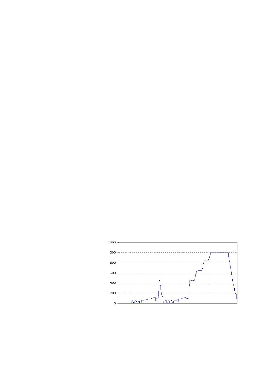
3.9.1 Examples of operation of the unbalancing control function
The following examples refer to an appliance with a final spin speed at 1000 rpm.
Load correctly balanced
Low
speed
FUCS phase 0 and pulse
Low
speed
FUCS phase 1
Normal
spin
SOI/DT 2002-06 eb
26
599 35 26-84
Load balanced after few attempts:
A: Low speed
B: FUCS phase 1
C: Normal spin
Load balanced after second phase:
A: Low speed
B: FUCS phase 1 with pulse at 470 rpm
C: Low speed
D: FUCS phase 2
E: Normal spin
Load balanced after second phase and anti-foam
control function:
A: Low speed
B: FUCS phase 1 with pulse at 470 rpm
C: Low speed
D: FUCS phase 2
E: Spin with anti-foam function
F: Low speed
G: FUCS phase 3
H: Normal spin
Load slightly unbalanced after third phase:
A: Low speed
B: FUCS phase 1 with pulse at 470 rpm
C: Low speed
D: FUCS phase 2
E: FUCS phase 3
F: Reduced spin
Load unbalanced after third phase:
A: Low speed
B: FUCS phase 1 with pulse at 470 rpm
C: Low speed
D: FUCS phase 2
E: FUCS phase 3
F: the spin phase is skipped and the appliance passes
to the subsequent phase
SOI/DT 2002-06 eb
27
599 35 26-84
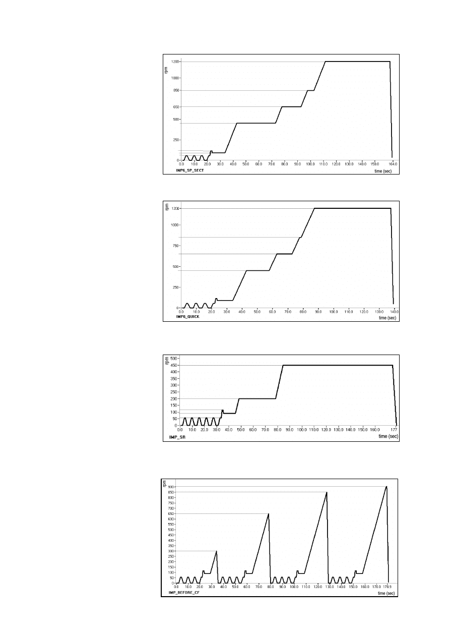
3.10 Spins
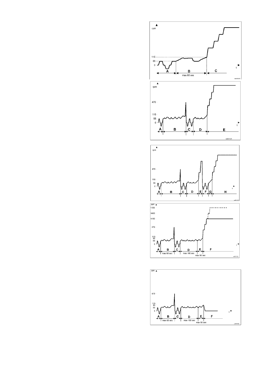
3.10.1 Spin IMP_C0_INP_SECT
•
prewash cotton and synthetics, penultimate synthetics rinse (1
st
part)
3.10.2 Spin IMP_C0_SP_SECT
•
prewash cotton and synthetics, penultimate synthetics rinse (2
nd
part)
3.10.3 Spin IMP5
•
final
synthetics
3.10.4 Spin IMP7
•
final
delicates
SOI/DT 2002-06 eb
28
599 35 26-84
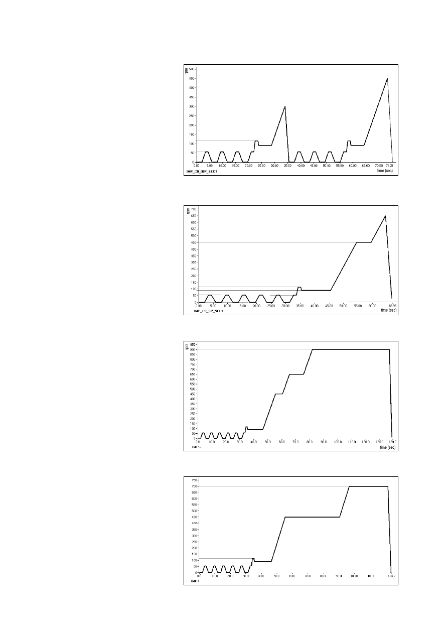
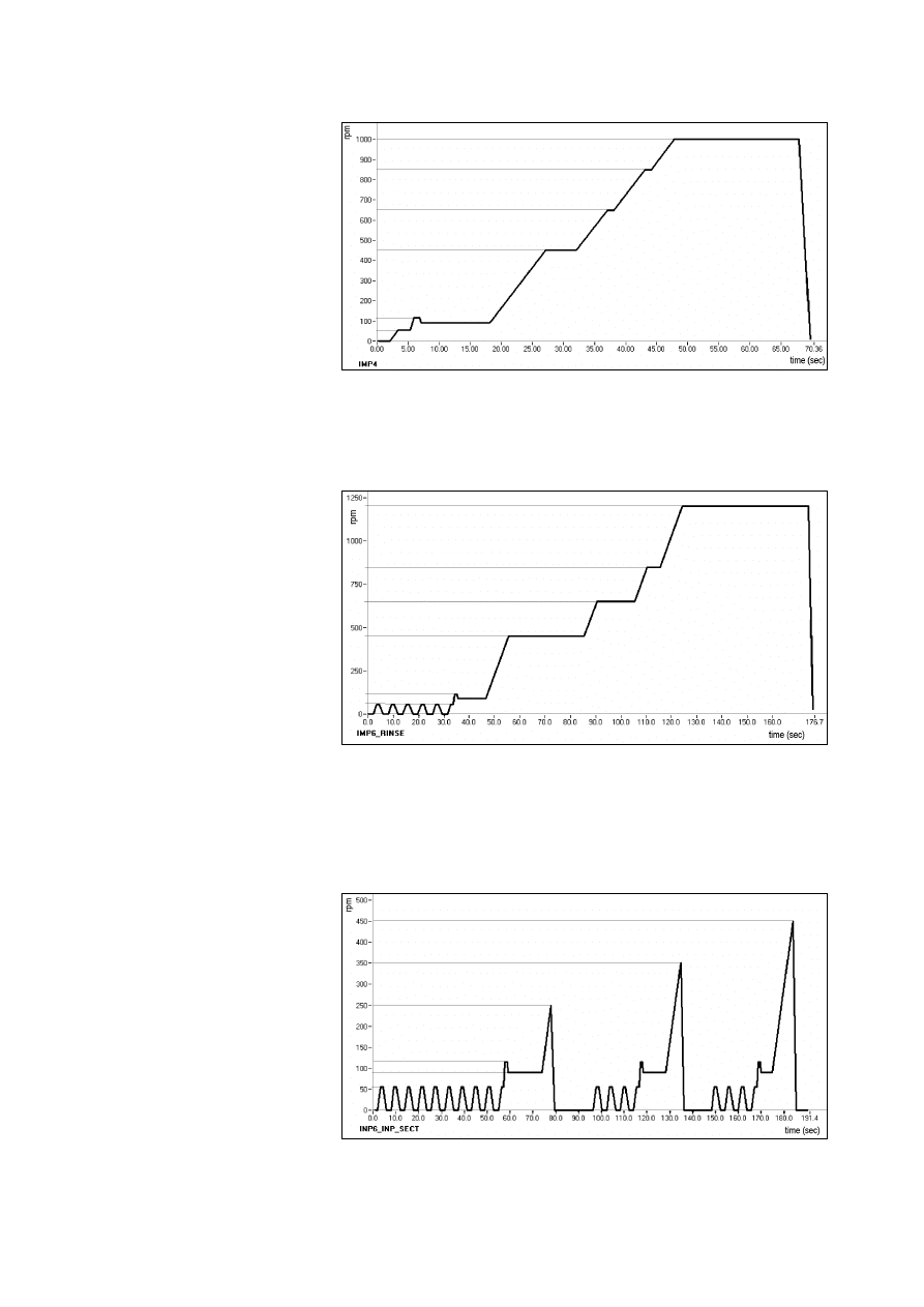
3.10.5 Spin IMP4
•
final
wool
3.10.6 Spin IMP6-RINSE
•
intermediate cotton rinses (the speed can be configured)
3.10.7 Spin IMP6_INP_SECT
•
cotton final wash phase (1
st
part)
SOI/DT 2002-06 eb
29
599 35 26-84
3.10.8 Spin IMP6_SP_SECT
•
cotton final wash phase (2
nd
part)
3.10.9 Spin IMP6_QUICK
•
cotton final and intermediate wash phase with “short” option
3.10.10 Spin IMP_SR
•
intermediate with “super-rinse” option
3.10.11 Spin IMP_BEFORE_CF
•
precedes the cotton final spin if the drying is selected at the end of the washing cycle (washer dryers)
SOI/DT 2002-06 eb
30
599 35 26-84
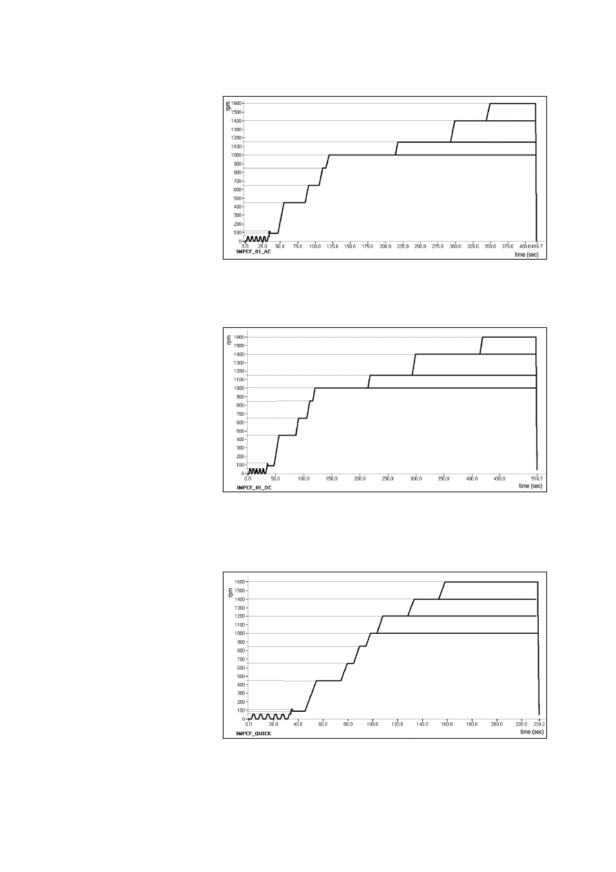
3.10.12 Spin IMPCF_01_AC
•
cotton final with AC motors
3.10.13 Spin IMPCF_01_DC
•
cotton final with DC motors
3.10.14 Spin IMPCF_QUICK
•
cotton final with “short” option
SOI/DT 2002-06 eb
31
599 35 26-84
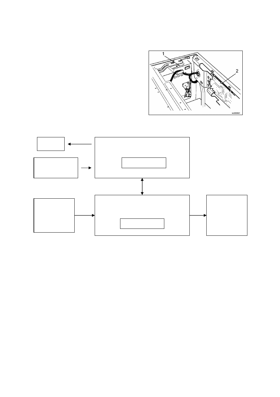
4 Technical
characteristics
4.1 EWM2000 Electronic control unit
1. Main PCB
2. Control/Display Board
The main PCB performs the following functions:
•
acquisition of the wash cycle settings via the control/display board.
•
control of the water level in the tub via the electronic pressure switch and the safety pressure switch.
•
control of the temperature of the washing solution via an NTC sensor.
•
control of the speed of rotation of the motor via a signal from the tachometric generator.
•
powering of all the electrical components in the washing machine and control of the wash cycle
BUZZER
CONTROL BOARD
Microprocessor
PROGRAMME
SELECTOR
MAIN BOARD
Microprocessor
SENSORS
ELECTRICAL
LOADS
SOI/DT 2002-06 eb
32
599 35 26-84
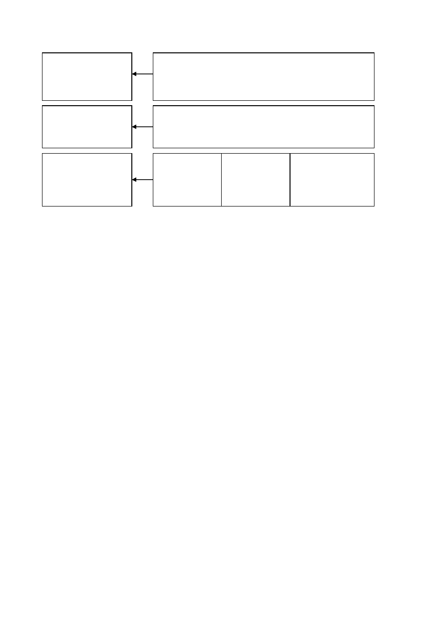
4.1.1 Memories of the microprocessor (main PCB)
The overall structure of the microprocessor memory on the main PCB is subdivided into three sections:
ROM
This area of memory contains the software with the general instructions that control the operation
of the appliance, such as those of the electrical components and alarms. The ROM is set up by
the manufacturer of the microprocessor, and cannot be modified.
RAM
This part of memory contains all the variables used during the execution of the wash programme,
which are written in dynamic format. The RAM can be read using a DAAS interface.
EEPROM This area of memory contains:
Ö
the data necessary to restart the appliance in case of a power failure.
Ö
the parameters for the wash cycle, such as water fill level, speed and type of motor movement, and the
temperature during the various phases of the wash cycle. Once written, this data is protected and,
normally, can be read only using a DAAS interface
Ö
data relative to the configuration of the appliance, such as the speed of the final spin phase, the volume
of the tub, the type of washing system, etc. This data may be entered either via a DAAS interface or via
the control/display board.
ENTERING DATA INTO THE EEPROM
All the data is entered into the EEPROM on the production line of the washing machines using a computer
with a DAAS interface.
In the field, the configuration only can be modified using a combination of buttons on the control/display
board.
ROM
RAM
EEPROM
POWER FAIL
&
MACHINE
STATUS
CYCLE
PARAMETERS
MACHINE
CONFIGURATION
GENERAL INSTRUCTIONS
PROGRAMME VARIABLES
SOI/DT 2002-06 eb
33
599 35 26-84
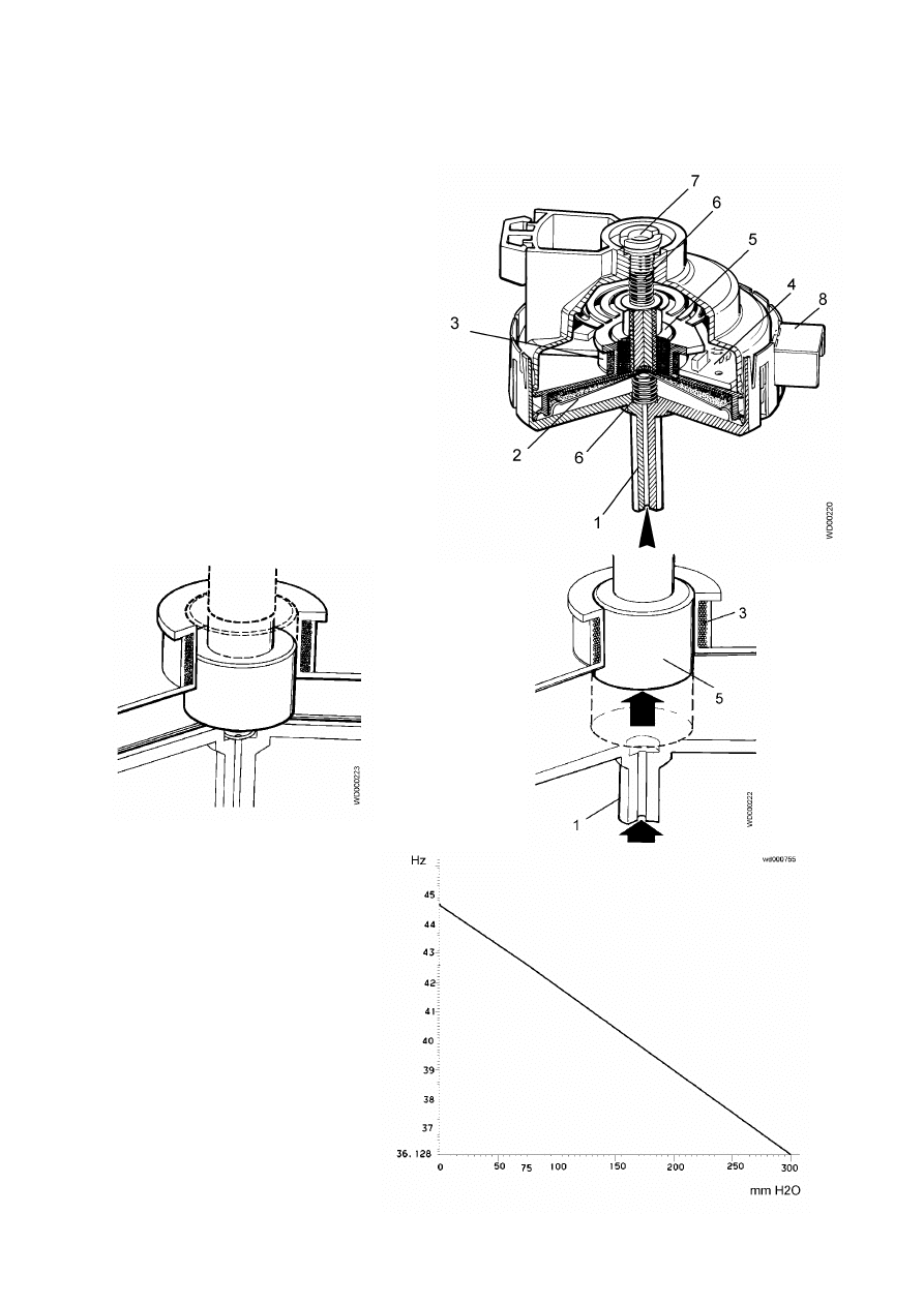
4.2 Analog pressure switch (electronic)
The electronic pressure switch is an analog device that controls the water level in the tub. It is directly
connected to the main electronic PCB.
1. air inlet hose
2. diaphragm
3. coil
4. electronic circuit
(oscillator)
5. core
6. spring
7. calibration screw
8. connector
The pressure switch is connected by a hose to
the pressure chamber.
When the tub is filled with water, the pressure
created inside the hydraulic circuit expands the
diaphragm. This in turn modifies the position of
the core inside the coil, thus changing the
inductance and the frequency of the oscillating
circuit.
The electronic PCB, according to the
frequency, recognizes the quantity of the
water in the tub.
Frequency variation according to
pressure
SOI/DT 2002-06 eb
34
599 35 26-84
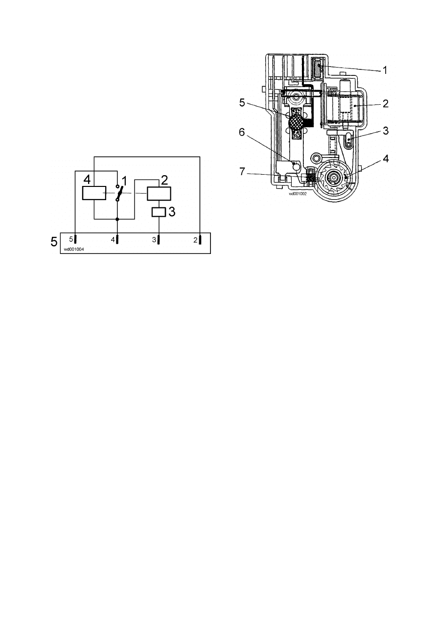
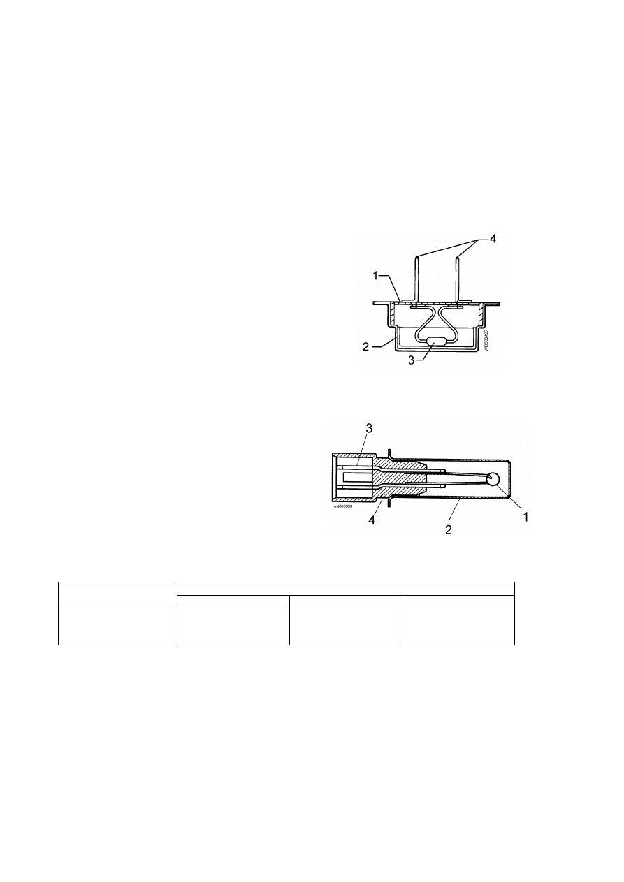
4.3 Instantaneous door safety device
Certain models are fitted with an instantaneous door
safety device; this means that the door can be opened
as soon as the drum stops rotating.
1. PTC solenoid protector
2. Solenoid
3. Lever mechanism
4. Cam
5. PTC - bimetal
6. Electrical contacts (main switch)
7. Latch
1. Main
switch
2. Solenoid
3. PTC solenoid protection
4. Bimetal
PTC
5. Connector
Operation principle
When the ON/OFF button is pressed to switch the appliance on, the bimetal PTC is powered; the cam is in
a position which prevents the latch from moving outwards.
When the START/PAUSE button is pressed to start the programme, the main PCB transmits a signal
(duration 20 msec) to the solenoid (at least 6 seconds after the appliance is switched on). The solenoid
causes the cams to rotate one position. This raises the latch which holds the cursor of the door safety
device in position and, at the same time, closes the contacts of the main switch, which thus powers all the
components in the appliance.
At the end of the programme, the board transmits two signals (at an interval of 200 msec and having the
same 20 msec duration):
- the first signal moves the cams a further position, though without releasing the latch.
- the second signal (which is transmitted only if the system functions correctly) moves the cams another
position, which causes the latch to retract, thus releasing the safety device. At the same time, the
contacts of the main switch are opened.
Conditions of door opening
Before transmitting the door aperture signal, the main PCB checks that the following conditions are
observed:
•
the drum must be stationary (i.e. no signal received from the tachometric generator)
•
the water must not be above the lower lip of the door
•
the temperature of the water must be not more than 40°C.
Automatic release device
In case of a power failure, or if the appliance is switched off using the ON/OFF button, or if the solenoid
should malfunction, the bimetal PTC cools over a period varying from 55 seconds to 4 minutes (at a
temperature of 65°C), after which the door lock is released.
Solenoid protection
A PTC is connected in series with the solenoid with the purpose of limiting the current (and thus possible
overheating) in the following cases:
•
TRIAC on the main PCB short-circuited
•
Repeated actioning of the START/PAUSE button (more than 10 times)
SOI/DT 2002-06 eb
35
599 35 26-84
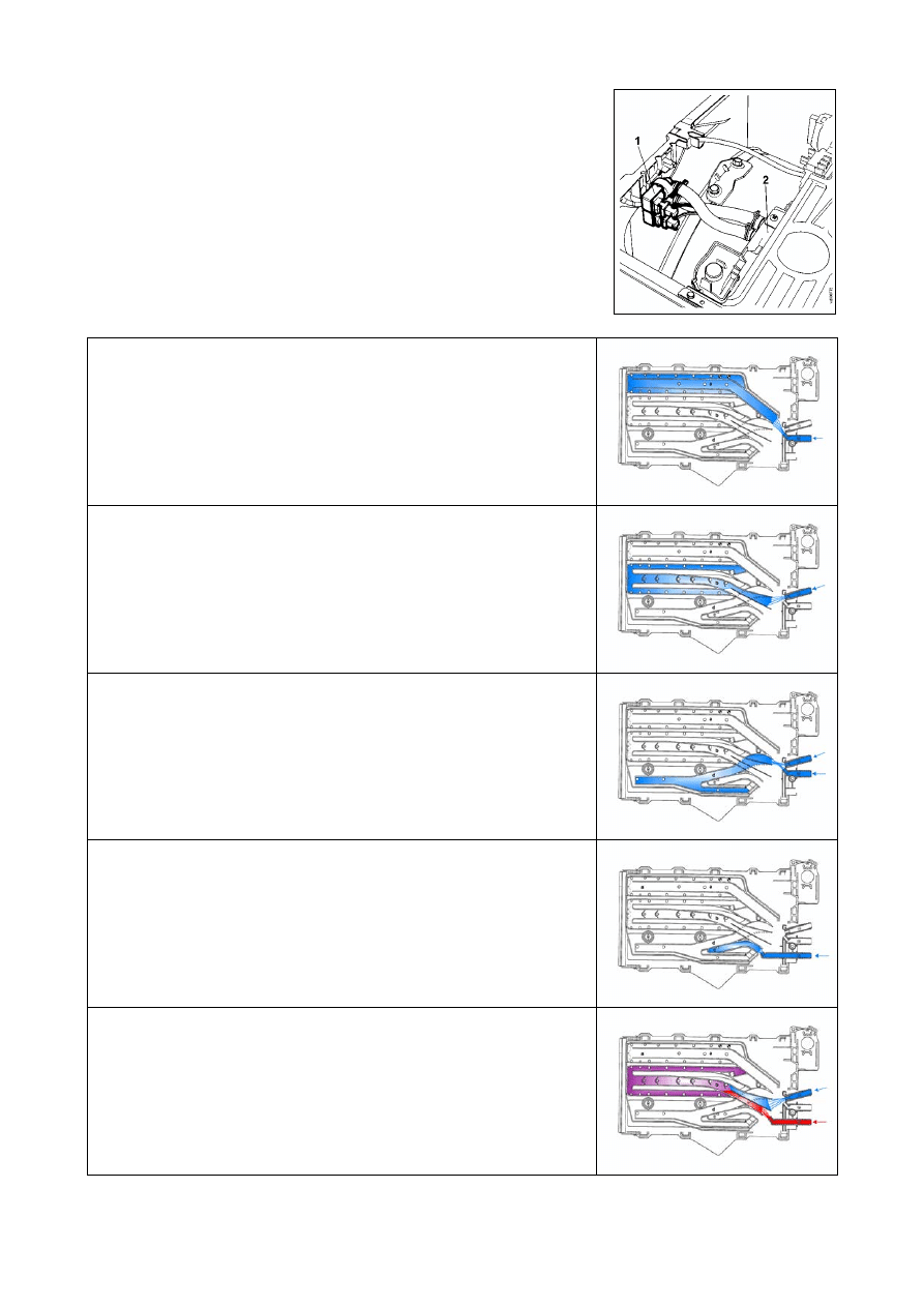
4.4 Detergent
dispenser
Water is ducted into the detergent dispenser by a solenoid valve with
one inlet and two or three outlets. Some models are fitted with a second
solenoid valve for hot water fill.
The same detergent dispenser is used in all models; the only difference
lies in the water intake nozzle. The detergent dispenser may consist of
three or four compartments.
1. Solenoid valve
2. Detergent dispenser
Water fill to pre-wash compartment
(pre-wash solenoid)
•
The detergent contained in the “a” compartment filled at the start of
the pre-wash.
•
In some models, with “stains” option, the “a” compartment can be
used alternatively to contain the stain remover, which is filled during
the wash phase.
Water fill to wash compartment
(wash solenoid)
•
The “b” compartment is used to contain the detergent that is filled at
the start of the wash cycle.
Water fill to softener compartment
(pre-wash and wash solenoids)
•
The “d” compartment is used to contain the softener that is filled at
the start of the last rinse
Water fill to bleach compartment
(bleach solenoid)
•
In
models
with
4-compartment dispenser water is filled into “c”
compartment at the start of the last rinse.
Hot water fill
(hot water/wash solenoids)
•
In models with hot water solenoid the hot water/wash solenoids are
actioned simultaneously to fill water mixed in the wash compartment.
SOI/DT 2002-06 eb
36
599 35 26-84
4.5 Power supply to the motor
The main PCB powers the motor directly via a TRIAC. Reversal of the direction of the motor is effected by
two relays that vary the connection between the rotor and the stator.
A third relay powers the stator in half- or full-range operation, depending on the spin speed.
The speed of the motor is controlled by a signal received from the tachometric generator.
During the spin cycles, the microprocessor checks for an unbalanced load and for excessive foam.
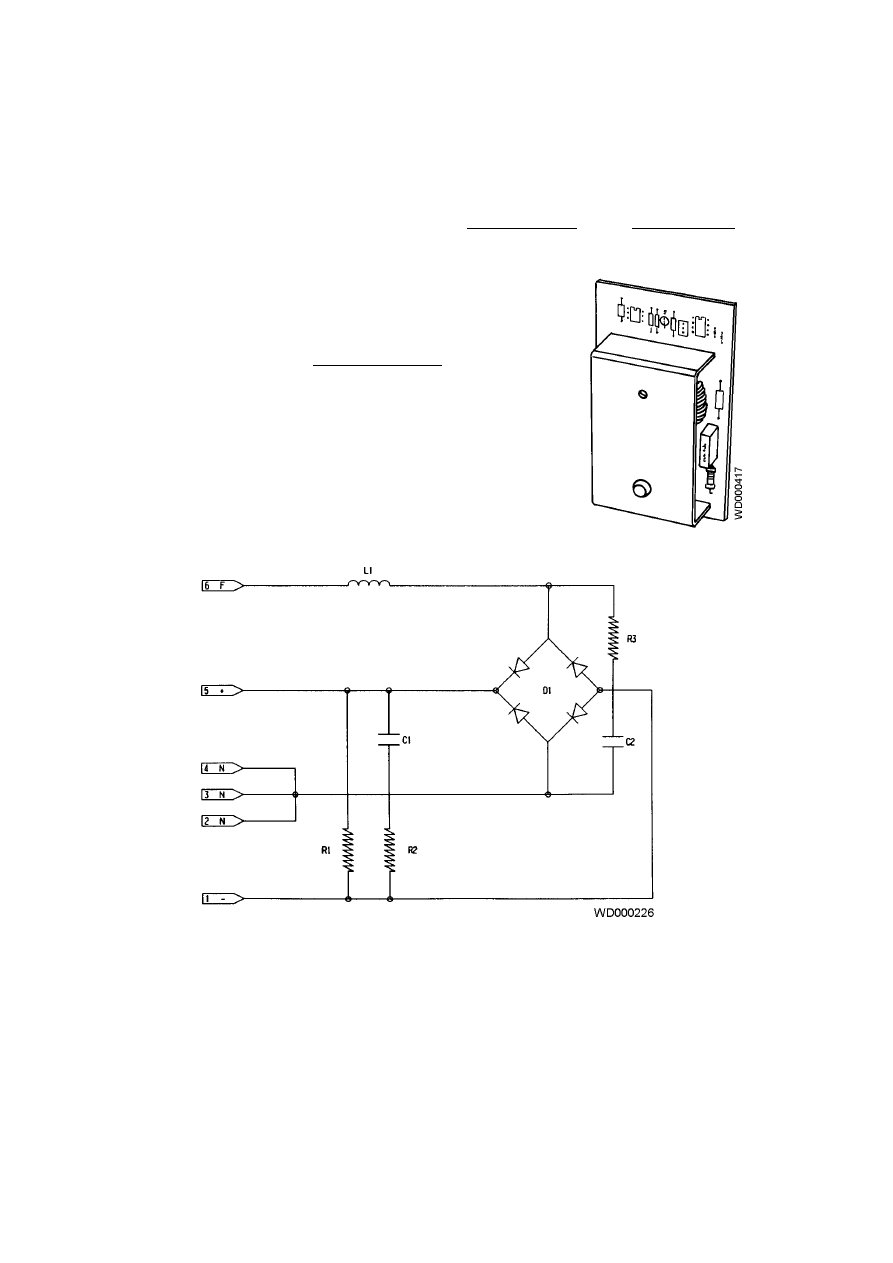
4.5.1 AC/DC Converter
This component, which is fitted to certain models only, serves to
convert the alternating current generated by the TRIAC on the
main PCB into a direct current to power the drum motor.
L1 1.2
mH
R1 68
K
Ω
D1 25A/600V
R2-R3
100
Ω
C1-C2 47
µ
F
SOI/DT 2002-06 eb
37
599 35 26-84
4.6 Circulation
pump
In Jetsystem models, the circulation pump is powered directly by the main PCB via a TRIAC.
4.7 Heating
The heating element is powered directly by the main PCB via a relay.
As a safety feature, a traditional dual-level pressure switch (anti-boiling 1 and anti-boiling 2) is connected in
series to the heating element.
The temperature is controlled directly by the main PCB via an NTC temperature sensor. Two versions of the
NTC sensor exist, depending on the type of tub; their shape is different, but their characteristics are
identical.
1. Plastic casing
2. Metallic capsule
3. NTC resistor
4. Terminals
1. NTC resistor
2. Metallic capsule
3. Terminals
4. Plastic casing
RESISTANCE (
Ω
)
TEMPERATURE
(ºC)
Rated
Maximum
Minimum
20
60
80
6050
1250
640
6335
1278
620
5765
1222
660
4.8 Drain
cycle
The drain pump is powered directly by the main
PCB via a TRIAC.
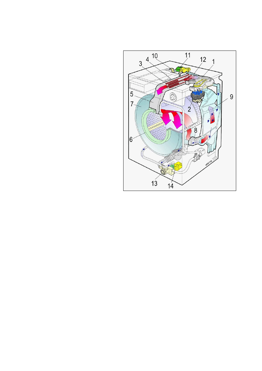
SOI/DT 2002-06 eb
38
599 35 26-84
5 Drying
circuit
(washer-dryers)
The drying system is identical to that used for washer/dryers with traditional timers.
1. Fan
2. Fan motor
3. Drying heating elements
4. Heating element casing
5. Duct
6. Door gasket
7. Tub
8. Tub-condenser hose
9. Drying condenser
10. Manifold
11. Condensation water inlet valve
12. Condenser-manifold pipe
13. Body filter
14. Drain pump
Automatic drying cycles: the drying time is controlled by the microprocessor to provide the desired level of
humidity.
The drying cycle may be carried out at the end of the washing cycle or separately.
Three types of drying can be selected:
•
Extra dry (for cotton only)
•
Cupboard dry (cotton and synthetics)
•
Iron dry (for cotton only)
Time-controlled cycles: the drying time is selected by the user (maximum 130 minutes for cottons, 100
minutes for synthetics).
Cooling: At the end of all drying cycles, a cooling phase takes place.
The drying heater is powered directly by the main PCB via two relays and the contacts of the safety
pressure switch.
In cycles for synthetic fabrics, drying takes place with only one of the branches of the heating element in
operation (half-power). For cotton cycles, both branches of the heating element are used (full power).
The fan motor is powered by a different relay; the solenoid valve is powered by a TRIAC.
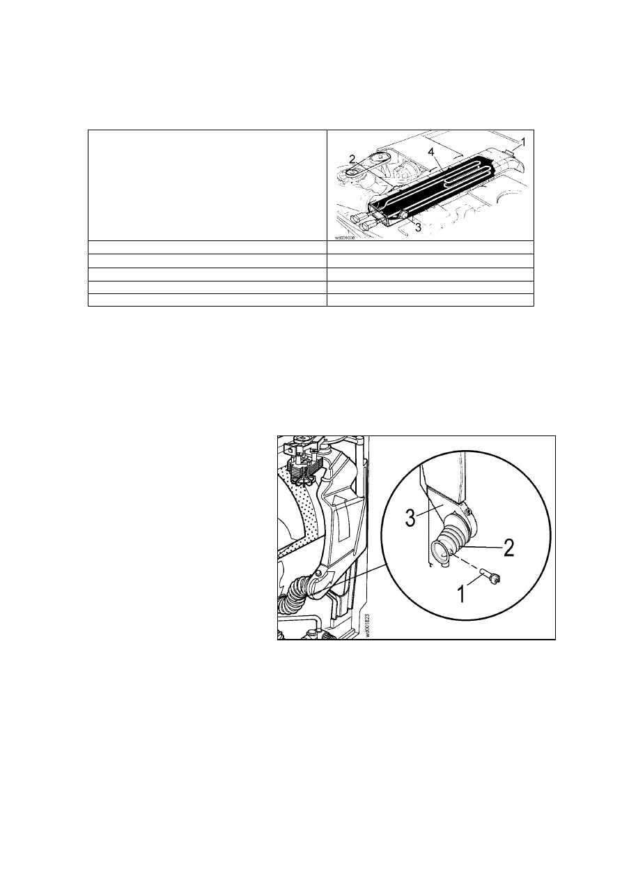
SOI/DT 2002-06 eb
39
599 35 26-84
5.1.1 Temperature control
An NTC sensor fitted to the duct is used to control the drying temperature; two safety thermostats (one of
which is a manual-reset type) are fitted to the casing of the heating element).
1. NTC sensor for control of drying
temperature
2. Automatic-reset safety thermostat
3. Manual-reset safety thermostat (150ºC)
4. Drying
heater
NTC Sensor : resistance at 25
°
C
5000
Ω
Manual-reset safety thermostat
Normally closed, opens at 150
°
C
Automatic-reset safety thermostat
Normally closed, opens at 98
°
C
Drying heater power
700 + 700 W
Fan rate
about 55 m
3
– hour
5.1.2 Determining the drying time:
In automatic cycles, the NTC sensor fitted to the drying condenser is used to control the drying time.
1. NTC temperature sensor
2. Tub-condenser pipe
3. Drying
condenser
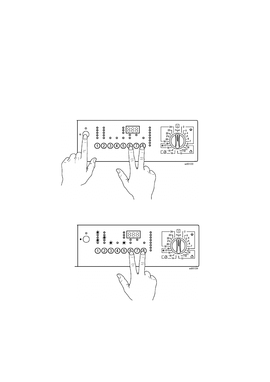
SOI/DT 2002-06 eb
40
599 35 26-84
6 Diagnostics
system
6.1 Access to diagnostics and configuration system
Using a single procedure, it is possible to access both the diagnostics and configuration systems. After
accessing this function, the following operations can be performed:
control of the operation of each of the components in the appliance
analysis of alarm conditions
configuration of the main PCB
To access the system:
Ö
reset the set programme and switch off the appliance
Ö
turn the programme selector to “reset” position
Ö
press the START/PAUSE button (8) together with one of the other buttons and then, holding down both
buttons, switch on the appliance with the button ON/OFF
Ö
hold both buttons down until the buzzer (if featured) sounds and the LEDs begin to flash (about 4
seconds).
If the main PCB has not been configured, it is possible only to perform the test on the display board and the
configuration procedure.
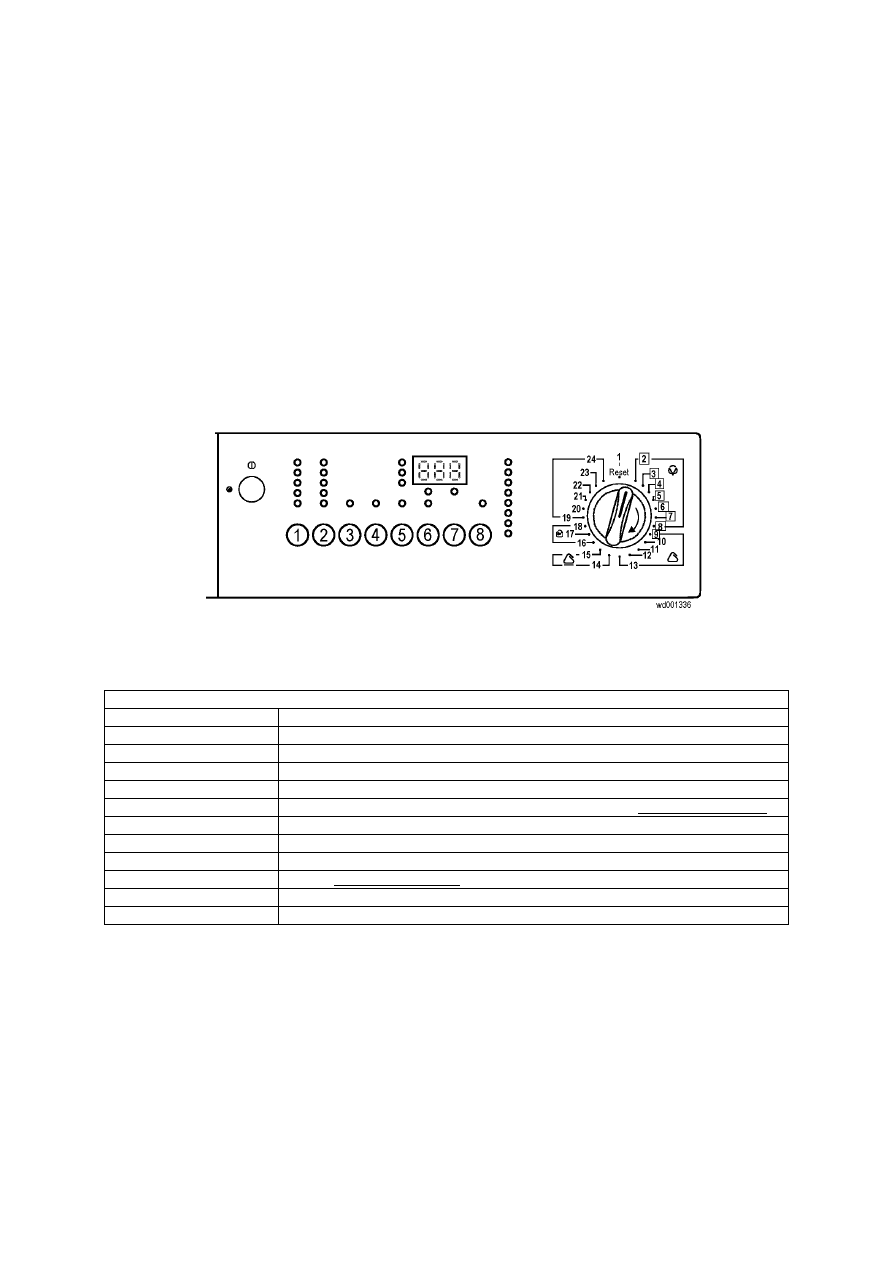
SOI/DT 2002-06 eb
41
599 35 26-84
6.2 Diagnostics
system
Correct operation of all the components in the appliance can be checked by turning the programme selector
knob.
The diagnostics cycles can be performed only if there is correct communication (connection) between the
main PCB and the display board; also, the configuration of the appliance must be correct.
The wash phase LEDs (and the display, if featured) show the binary code representing the closure of the
programme selector contacts for two seconds.
After two seconds, all the LEDs switch off and the diagnostics cycle corresponding to the position of the knob
is performed.
If an alarm condition occurs during the diagnostics cycle, operation of the appliance is interrupted, and the
LEDs (and display) show the corresponding alarm code (flashing).
If the selector knob is turned on OFF position, the machine will exit the diagnostic cycle!
DIAGNOSTIC CONTROL SYSTEM
Programme selector
Function tested
1
Tests the display board
2
Water fill to wash compartment in the dispenser
3
Water fill to pre-wash compartment in the dispenser
4
Water fill to conditioner compartment in the dispenser
5
Hot water fill or cold water fill to bleach compartment (certain models only)
6
Heating and, in Jetsystem models, circulation pump
7
Rotation of drum at 250 rpm with water in the tub (test for leaks from tub)
8
Drain and spin at maximum speed; pressure switches.
9
Drying (washer/dryers only)
23
Displays the last alarm
24
Configuration of the main electronic board
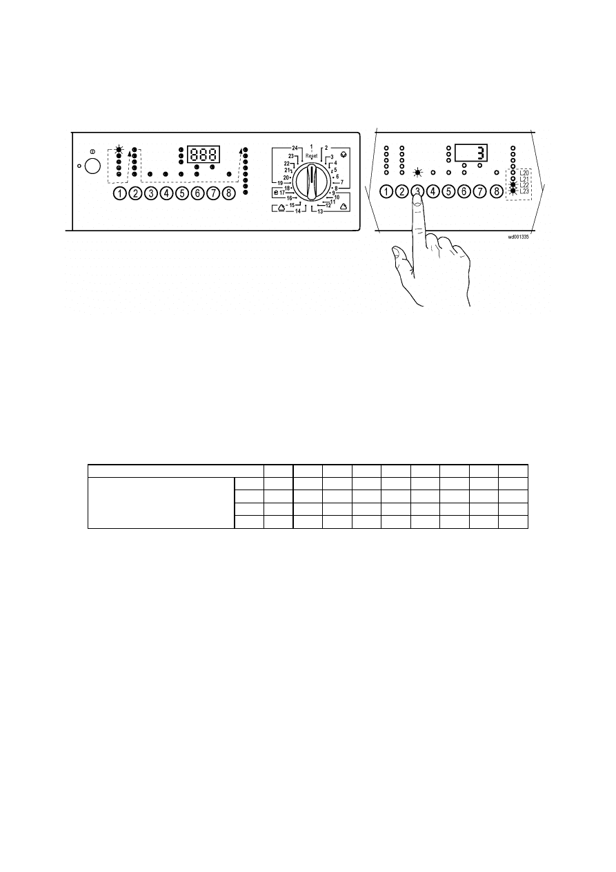
SOI/DT 2002-06 eb
42
599 35 26-84
6.3 Display board diagnostics
After accessing the diagnostics system, the display board is checked for correct operation. All the LEDs
(and, if featured, the display) light in sequence.
When the various buttons are pressed, the corresponding LEDs light. The display shows a binary code
corresponding to the code of the button pressed and the buzzer sounds.
On models that do not feature a display window, the code is displayed by the washing phase LEDs in binary
format.
Key to button codes
BUTTON
N°
0 1 2 3 4 5 6 7 8
L20 ❍
❍
❍
❍
❍
❍
❍
❍
●
L21 ❍
❍
❍
❍
●
●
●
●
❍
L22 ❍
❍
●
●
❍
❍
●
●
❍
LED
L23 ❍
●
❍
●
❍
●
❍
●
❍
❍
LED
OFF
●
LED ON
The display board test is performed automatically even if the board is powered while not connected to the
main PCB and the programme selector.
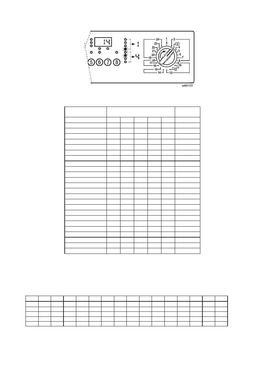
SOI/DT 2002-06 eb
43
599 35 26-84
6.3.1 Programme
selector
The table below shows the closure sequence of contact C6 (common) and the other contacts (C1 - C5) of
the programme selector in the various positions, as well as the light-up sequence of the display.
24-position
selector knob
Closure of selector contacts
(C6 - common)
Display
Code
C1 C2 C3 C4 C5
1 - RESET
0 1 1 1 1 1 E
2
0 1 0 0 1 0 6
3
0 1 1 0 0 1 4
4
0 1 0 1 0 0 C
5
0 1 1 1 0 1 C
6
0 0 0 1 1 0 A
7
1 0 0 0 0 0 1
8
1 0 0 0 1 0 3
9
1 0 0 1 0 0 9
10
0 1 0 1 1 0 E
11
0 0 1 0 1 1 2
12
1 0 0 1 1 0 b
13
1 0 1 0 0 1 1
14
0 0 1 1 0 1 8
15
1 0 1 0 1 1 3
16
0 0 1 1 1 1 A
17
1 0 1 1 0 1 9
18
1 0 1 1 1 1 b
19
1 1 0 0 0 0 5
20
0 1 1 0 1 1 6
21
0 0 0 0 1 0 2
22
0 1 0 0 0 0 4
23
0 0 0 1 0 0 8
24
0 0 1 0 0 1 0
The binary code flashes on the wash phase LEDs (and on the display):
Ö
The first four LEDs indicate the first digit of the code
Ö
The second four LEDs indicate the second digit of the code
Binary codes
0 1 2 3 4 5 6 7 8 9 10 11 12 13 14 15
A
b
C
d
E
F
❍
❍
❍
❍
❍
❍
❍
❍
●
●
●
●
●
●
●
●
❍
❍
❍
❍
●
●
●
●
❍
❍
❍
❍
●
●
●
●
❍
❍
●
●
❍
❍
●
●
❍
❍
●
●
❍
❍
●
●
❍
●
❍
●
❍
●
❍
●
❍
●
❍
●
❍
●
❍
●
❍
LED
OFF
●
LED ON
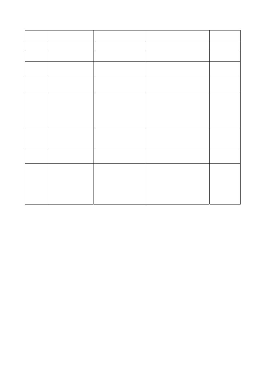
SOI/DT 2002-06 eb
44
599 35 26-84
6.4 Diagnostics
cycle
Knob
position
Function
tested
Components
actioned
Operating
conditions
Parameters
displayed
2
Water fill to wash
compartment
- door
interlock
- wash solenoid
Door closed, water fill to anti-
overflow level for max. 10 min
Water level in
mm
3
Water fill to pre-wash
compartment
- door
interlock
- pre-wash solenoid
Door closed, water fill to anti-
overflow level for max. 10 min
Water level in
mm
4
Water fill to conditioner
compartment
- door
interlock
- pre-wash solenoid
- wash solenoid
Door closed, water fill to anti-
overflow level for max. 10 min
Water level in
mm
5
Hot water fill or fill to
bleach compartment
(certain models only)
- door
interlock
- hot water or bleach
solenoid
Door closed, water fill to anti-
overflow level for max. 10 min
Water level in
mm
6
Heating (and, in
Jetsystem models,
recirculation)
- door
interlock
- (wash solenoid if level is
lower than the
antiboiling device)
- recirculation
pump
(Jetsystem models)
- heating
element
Door closed, water fill to above
anti-boiling level if not yet
reached, heating for max. 5
min or to 55°C (*)
Water
temperature in
°C
7
Check for leaks from
tub
- door interlock
- (wash solenoid if level is
<150mm)
- motor
Door closed, water fill above
150mm level if not yet reached,
motor until the drum reaches
250 rpm
Motor speed
(rpm)
8
Drain and spin, check
for pressure switch
congruency
- door
interlock
- drain
pump
- motor
Door closed, water drain, motor
movement, until maximum spin
speed is reached
Motor speed
(rpm ÷ 10)
9
Drying (washer/dryers
only)
- door
interlock
- drain
pump
- drying heater (full
power)
- fan
motor
- condensation
solenoid
Door closed, water drain to a
level lower than the anti-boiling
device, drying heater for max.
10 min or until the drying
temperature sensor (fitted to
the duct) detects a temperature
of 150°C
NTC drying
temperature
sensor on duct
and condenser
(in °C,
displayed
alternately for 2
sec)
(*)When the max. time is exceeded (timeout) error E61 is normally displayed (insufficient heating during
wash) since, although the heating is performed with the drum still, not every appliance can reach the
55
°
C temperature in 5 minutes.
In most cases this time is sufficient to control the heating; to reach the pre-set temperature, repeat this
phase without draining the water (skip for a while to another diagnostics phase and then go back to
heating control phase again).
If an alarm condition occurs during the course of the diagnostics cycle, the appliance stops and the display
or LEDs flash to indicate the alarm code.
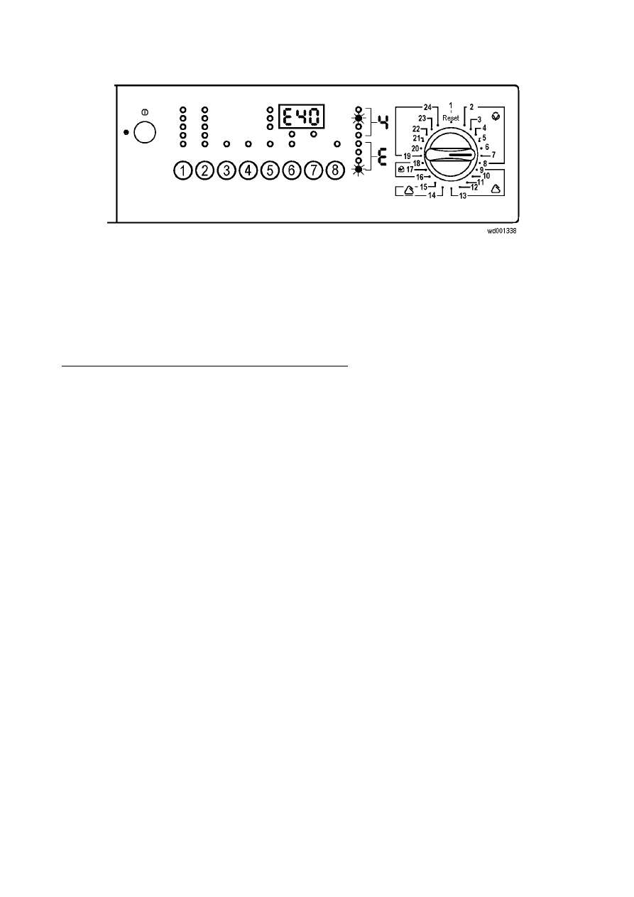
SOI/DT 2002-06 eb
45
599 35 26-84
6.5 Alarms
The electronic control unit detects and recognises any malfunctions in the operation of the appliance, in
which case an alarm condition is generated. Alarm conditions may be of three types:
cycle
paused
cycle
blocked
current phase skipped
Only four alarm conditions are normally displayed to the user:
Ö
problems with water fill
Ö
problems with drain
Ö
door open
Ö
communication error between the electronic boards, or configuration error
In the first three cases, the cycle is paused so that the user can, if possible, solve the problem. The code
showing the type of alarm flashes on the display.
In models without a display window, the last wash phase LED (end) flashes; the code relative to the type of
alarm flashes on the first four LEDs (and on the display).
For example, in the case of alarm E41 (door open), the display will show E40. In models not featuring a
display window, as well as the end-of-cycle LED which indicates error "E", the second LED indicates 4 in
binary code.
As can be seen from the general alarm code table, E4.. alarm conditions include all alarms relative to door
closure problems:
- E41: door open
- E42: door interlock malfunction
- E43, E44, and E45: problems with main PCB or wiring
In the case of communication or configuration errors, the alarm is displayed immediately when the appliance
is switched on; in the event of configuration errors, the only possible action is to access the diagnostics
system.
The FILTER BLOCKED warning is signalled by the corresponding LED (if featured) only at the end of the
cycle; EF0 flashes on the display.
To exit the alarm condition, press START/PAUSE if the cycle is paused (this enables the appliance to
attempt to complete the operation under the control of the user) or, if the cycle has been interrupted, switch
off the appliance.
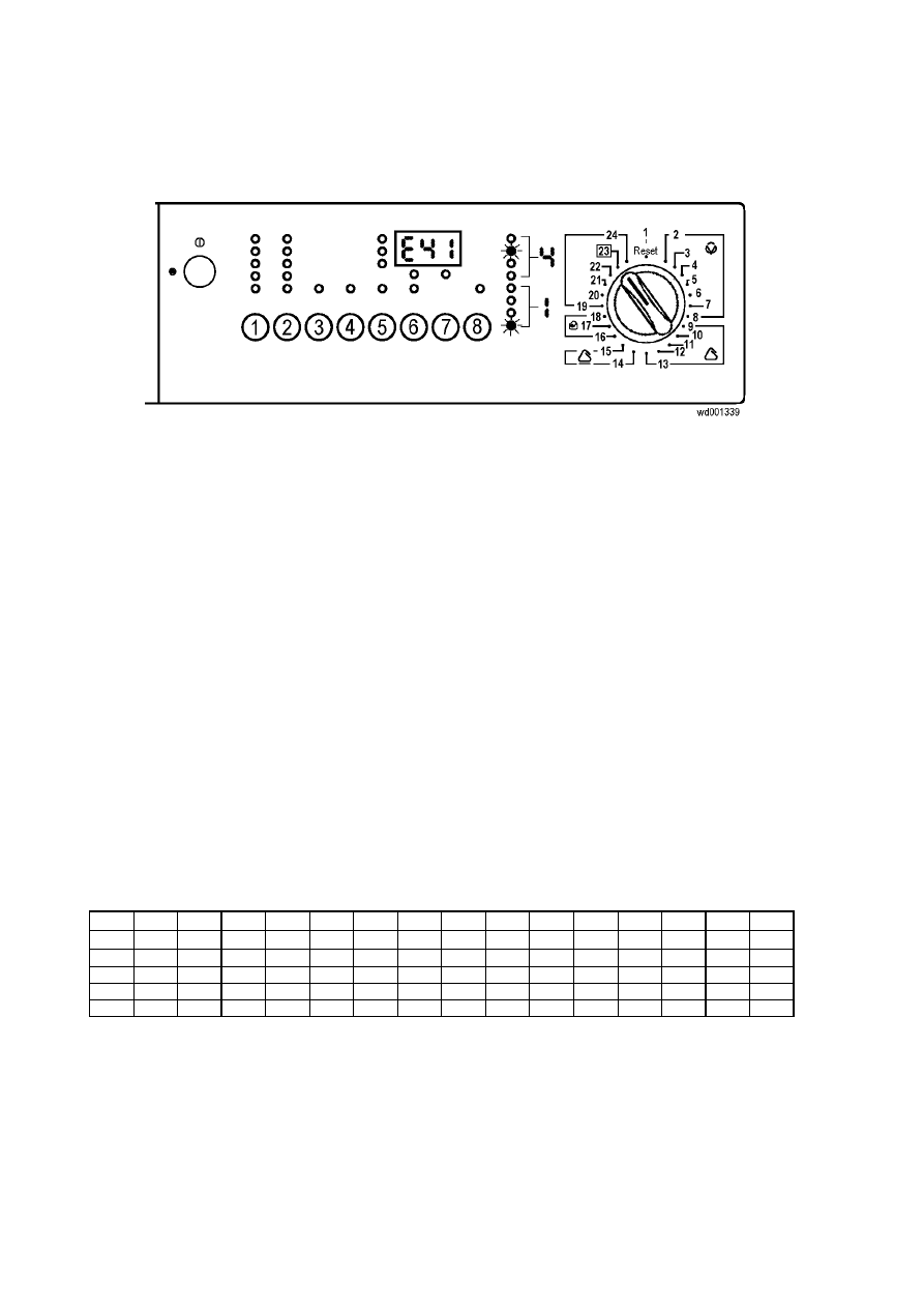
SOI/DT 2002-06 eb
46
599 35 26-84
6.6 Reading the last alarm condition
The diagnostics system makes it possible to identify the last alarm condition that occurred during the
operation of the appliance.
To read this alarm conditions, after accessing the diagnostics system, turn the programme selector knob
to
the last position but one (23)
The alarm condition is shown on the display, or the corresponding binary code flashes on the wash phase
LEDs.
Ö
The first four LEDs indicate the first digit of the alarm code
Ö
The second four LEDs indicate the second digit of the alarm code
For example, if an E41 alarm condition (door open) is generated, the display will show E41 or (if the
appliance does not feature the display window) the second LED in the first group (equivalent to 4 in binary
code) and the fourth LED in the second group (equivalent to 1 in binary code) will flash.
If no alarm condition has occurred, E00 is displayed
6.6.1 Diagnostics cycle alarms
If a malfunction should occur during the course of the diagnostics cycle, the relative alarm codes are
displayed. In this case, too, the wash phase LEDs (or the display) show the error code (flashing).
Binary codes
The table below shows how to convert the binary code displayed by the LEDs into the corresponding
decimal number.
0 1 2 3 4 5 6 7 8 9 10 11 12 13 14 15
A b C d E F
❍
❍
❍
❍
❍
❍
❍
❍
●
●
●
●
●
●
●
●
❍
❍
❍
❍
●
●
●
●
❍
❍
❍
❍
●
●
●
●
❍
❍
●
●
❍
❍
●
●
❍
❍
●
●
❍
❍
●
●
❍
●
❍
●
❍
●
❍
●
❍
●
❍
●
❍
●
❍
●
❍
LED
OFF
●
LED ON

SOI/DT 2002-05 eb
47
599 35 26-84
6.7 Alarm
codes
0:LED off 1: LED flashing
Alarm
code
LED
L16-19
LED
L20-23
Description of fault
User
code
Effect
Possible causes
E11
0
0
0
1
0
0
0
1
Problems with water fill in wash phase
(maximum 10 minutes for each fill phase)
E10
Cycle PAUSED Tap closed or mains pressure insufficient; solenoid
valve; hydraulic circuit of pressure switches;
pressure switches; wiring; main PCB
E12
0
0
0
1
0
0
1
0
Problems with water fill in drying phase
(maximum 10 minutes for each fill phase during
in the wash load untangling phase)
E10
Cycle PAUSED Tap closed or mains pressure insufficient; solenoid
valve; hydraulic circuit of pressure switches;
pressure switches; wiring; main PCB
E21
0
0
1
0
0
0
0
1
Problems with water drain in wash phase
(maximum 10 minutes for each drain phase)
E20
Cycle PAUSED Drain hose obstructed; filter blocked; drain pump;
pressure switches; wiring; main PCB
E22
0
0
1
0
0
0
1
0
Problems with water drain during drying or
drying condenser blocked
(anti-boiling pressure switch closed
on "full")
E20
Heating phase
skipped
Drain hose obstructed; filter blocked; drying
condenser blocked; drain pump; pressure switches;
wiring; main PCB
E31
0
0
1
1
0
0
0
1
Electronic pressure switch circuit faulty
(frequency of pressure switch signal out of
limits)
---
Cycle blocked
with door closed
Electronic pressure switch; wiring; main PCB
E32
0
0
1
1
0
0
1
0
Incorrect calibration of electronic pressure
switch (electronic pressure switch level different
from 0-66 mm after initial calibration drain and
anti-boiling pressure switch on "empty")
---
Cycle PAUSED Tap closed or mains pressure insufficient; solenoid
valve; hydraulic circuit of pressure switches;
pressure switches; wiring; main PCB
E33
0
0
1
1
0
0
1
1
Incongruence between level of electronic
pressure switch and level of anti-boiling
pressure switch 1 (duration of fault at least 60
seconds)
---
Cycle blocked
with door closed
Hydraulic circuit of pressure switches; electronic
pressure switch; pressure switch; wiring; main PCB
E34
0
0
1
1
0
1
0
0
Incongruence between level of electronic
pressure switch and level of anti-boiling
pressure switch 2 (duration of fault at least 60
seconds)
---
Cycle blocked
with door closed
Hydraulic circuit of pressure switches; electronic
pressure switch; pressure switch; wiring; main PCB
E35
0
0
1
1
0
1
0
1
Water level too high
(level of electronic pressure switch higher than
300mm for more than 15 seconds)
---
Cycle blocked
with door closed
and water drain
to 120mm
Solenoid valve; hydraulic circuit of pressure
switches; pressure switches; wiring; main PCB

SOI/DT 2002-05 eb
48
599 35 26-84
Alarm
code
LED
L18
÷
21
LED
L22
÷
25
Description of fault
User
code
Effect
Possible causes
E36
0
0
1
1
0
1
1
0
"Sensing" circuit of anti-boiling pressure switch
1 faulty
(input signal to microprocessor always 0V or
5V)
---
Cycle blocked
with door closed
Main PCB
E37
0
0
1
1
0
1
1
1
"Sensing" circuit of anti-boiling pressure switch
2 faulty
(input signal to microprocessor always 0 - 5V)
---
Cycle blocked
with door closed
Main PCB
E38
0
0
1
1
1
0
0
0
Pressure chamber blocked
(water level does not vary for at least 30 sec.
during drum rotation)
---
Heating phase
skipped
Pressure switch hydraulic circuit; pressure
switches, motor drive belt broken
E41
0
1
0
0
0
0
0
1
Door open
(door delay interlock does not close after 15
seconds)
E40
Cycle paused Door open; door delay interlock; wiring; main PCB
E42
0
1
0
0
0
0
1
0
Problems with door closure
(door open during cycle for more than 15 sec.
or door closed after cycle for more than 3 min.)
E40
Cycle paused Door delay interlock; wiring; main PCB
E43
0
1
0
0
0
0
1
1
TRIAC which powers the door interlock faulty
(incongruency between status of door interlock
"sensing" circuit and status of TRIAC)
E40
Cycle paused Wiring; main PCB
E44
0
1
0
0
0
1
0
0
"Sensing" circuit of door delay interlock faulty
(input signal to microprocessor always 0V or
5V)
---
Cycle blocked Main PCB
E45
0
1
0
0
0
1
0
1
"Sensing" circuit of door delay interlock triac
faulty (input signal to microprocessor always 0V
or 5V)
---
Cycle blocked
with door closed
Main PCB
E51
0
1
0
1
0
0
0
1
TRIAC which powers the motor short-circuited
(TRIAC short-circuit cut-out activated or motor
speed more than maximum speed)
---
Cycle blocked
with door closed
(after 5 attempts)
Loss of insulation on motor winding/wiring; main
PCB
E52
0
1
0
1
0
0
1
0
No signal from tachometric generator on motor
(no signal after maximum time)
---
Cycle blocked
with door closed
(after 5 attempts,
the last after 20
sec)
Motor; tachometric generator; wiring; main PCB

SOI/DT 2002-05 eb
49
599 35 26-84
Alarm
code
LED
L18
÷
21
LED
L22
÷
25
Description of fault
User
code
Effect
Possible causes
E53
0
1
0
1
0
0
1
1
"Sensing" circuit of motor TRIAC faulty
(input signal to microprocessor always 0V or
5V)
---
Cycle blocked
with door closed
Main PCB
E54
0
1
0
1
0
1
0
0
Relays contacts sticking
(voltage on "sensing" circuit when the relays
should be open)
---
Cycle blocked
with door closed
(after 5 attempts)
Loss of insulation on motor windings/wiring; main
PCB
E55
0
1
0
1
0
1
0
1
Motor circuit open
---
Cycle blocked
with door closed
(after 5 attempts)
Motor; wiring; main PCB
E56
0
1
0
1
0
1
1
0
Problems with motor tachimetric generator
---
Cycle blocked
with door closed
(after 5 attempts,
last after 20')
Motor (tachimetric generator);
wiring; main PCB
E61
0
1
1
0
0
0
0
1
Insufficient heating during washing
(maximum heating time exceeded)
---
Heating phase
skipped
NTC sensor incorrectly calibrated; heating element;
wiring; main PCB
E62
0
1
1
0
0
0
1
0
Overheating during washing
(temperature >88°C for more than 5 minutes)
---
Drain, cycle
blocked
Heating element (earthed); NTC sensor faulty;
wiring; main PCB
E64
0
1
1
0
0
1
0
0
Overheating during drying
(drying temperature >180°C detected by NTC
temperature sensor on duct)
---
Heating phase
for drying
skipped
Drying NTC sensor (duct); drying heater; wiring;
main PCB
E66
0
1
1
0
0
1
1
0
Power relay to heating element faulty
(incongruency between closure of anti-boiling
pressure switch 2 and status of relay K3)
---
Drain, cycle
blocked
Anti-boiling pressure switch 2; wiring; main PCB
E71
0
1
1
1
0
0
0
1
NTC wash sensor faulty
(voltage not within limits = short-circuit or open)
---
Heating phase
skipped
Wash NTC sensor; wiring; main PCB
E72
0
1
1
1
0
0
1
0
NTC sensor on drying condenser faulty
(voltage out of limits = short-circuit or open)
---
Heating phase
for drying
skipped
Drying NTC sensor (condenser); wiring; main PCB

SOI/DT 2002-05 eb
50
599 35 26-84
Alarm
code
LED
L18
÷
21
LED
L22
÷
25
Description of fault
User
code
Effect
Possible causes
E73
0
1
1
1
0
0
1
1
NTC sensor on drying duct faulty
(voltage out of limits = short-circuit or open)
---
Heating phase
for drying
skipped
Drying NTC sensor (duct); wiring; main PCB
E84
1
0
0
0
0
1
0
0
"Sensing" circuit on circulation pump triac
faulty
(input signal to microprocessor always 0V or
5V)
---
Drain, cycle
blocked (door
open)
Main PCB
E85
1
0
0
0
0
1
0
1
Circulation pump faulty
(incongruency between status of "sensing"
circuit on circulation pump and status of
TRIAC)
---
Drain, cycle
blocked (door
open)
Circulation pump; wiring; main PCB
E91
1
0
0
1
0
0
0
1
Communications error between main PCB and
display board
E90
---
Wiring; main PCB; display board
E92
1
0
0
1
0
0
1
0
Communications incongruency between main
PCB and display board
(versions not compatible)
E90
---
Main PCB; display board
E93
1
0
0
1
0
0
1
1
Configuration error
(incongruency of configuration values when
appliance is switched on)
E90
Cycle blocked Configuration error; main PCB
E94
1
0
0
1
0
1
0
0
Incorrect configuration of washing cycle
E90
Cycle blocked Cycle software error; main PCB
EF1
1
1
1
1
0
0
0
1
Drain filter blocked
(drain phase too long)
Specific
LED
(EF0)
---
Drain hose obstructed/kinked; drain filter
dirty/blocked
EF2
1
1
1
1
0
0
1
0
Excessive detergent
(too much foam during drains)
Specific
LED
(EF0)
---
Excessive detergent introduced; drain hose
obstructed/kinked; drain filter dirty
EF3
1
1
1
1
0
0
1
1
Water leakage:
intervention of Aqua Control system
---
Water drain to
120mm, cycle
blocked
Leaks from base; drain pump; wiring; main PCB
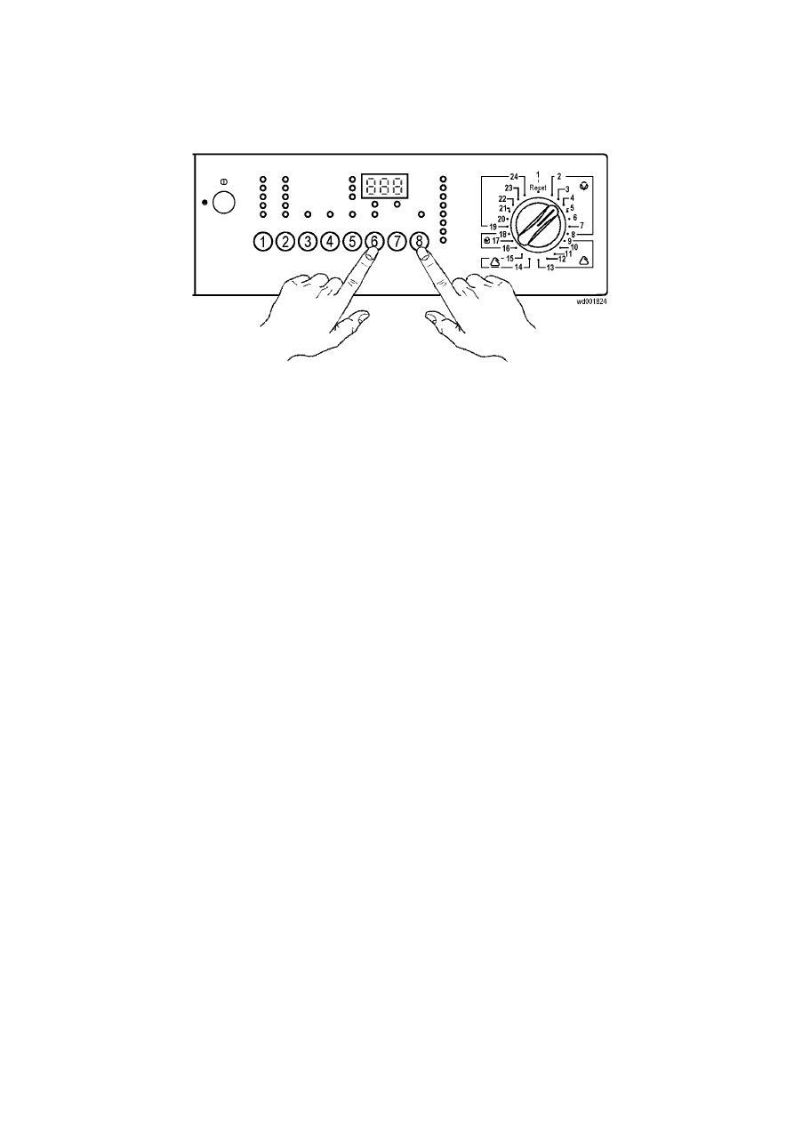
SOI/DT 2002-05 eb
51
599 35 26-84
6.8 Cancelling the last alarm condition
To cancel the last memorised alarm condition, press button Start/Pause no. 8 and no. 6 at the same time
during the course of the diagnostics cycle (2-9).
The alarm is cancelled also when a new configuration is given to the main PCB.
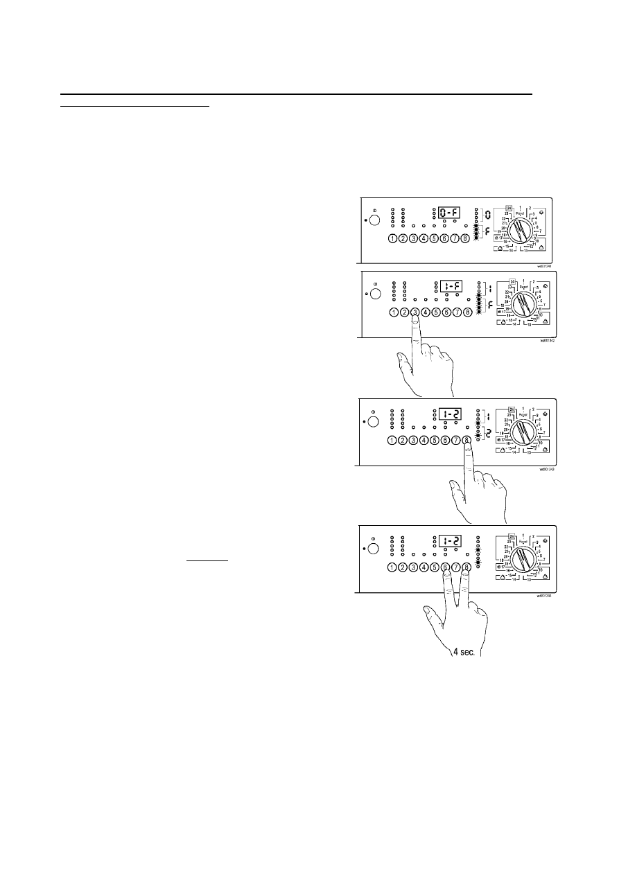
SOI/DT 2002-05 eb
52
599 35 26-84
6.9 Configuration of the main PCB
A standard main PCB is available as a spare part. This PCB contains only data relative to the wash cycle.
After replacing the main PCB, it is necessary to perform the configuration procedure in order to
operate the washing machine!
Configuration of the board consists of entering a 16-digit code which contains information which varies from
model to model (type of washing system, type of tub, spin speed, etc.).
To access the machine configuration procedure, first enter the diagnostics system, and then:
Ö
turn the programme selector to the last position
(24); the code relative to the programme selector is
displayed and after 2 seconds the code relative to the
first of the 16 digits of the configuration code (position
0) is displayed
Ö
when one of the option buttons is pressed (with the
exception of the START/PAUSE button), all the
digits, which make up the configuration code, are
displayed in sequence
Ö
press the START/PAUSE button (8) to modify the
configuration code (digit by digit)
Ö
when all 16 digits have been entered, check that the
code is correct, then memorize the code by pressing
the START/PAUSE button and one of the option
buttons at the same time; these buttons should be
held down for at least 4 seconds (i.e. the buzzer
sounds).
If the configuration is not entered correctly, the wash cycle will not start when the START button is pressed.
When configuration has been completed, perform the diagnostics routine in order to check that the
appliance functions correctly. In case of an error, the display window will show error code E93.
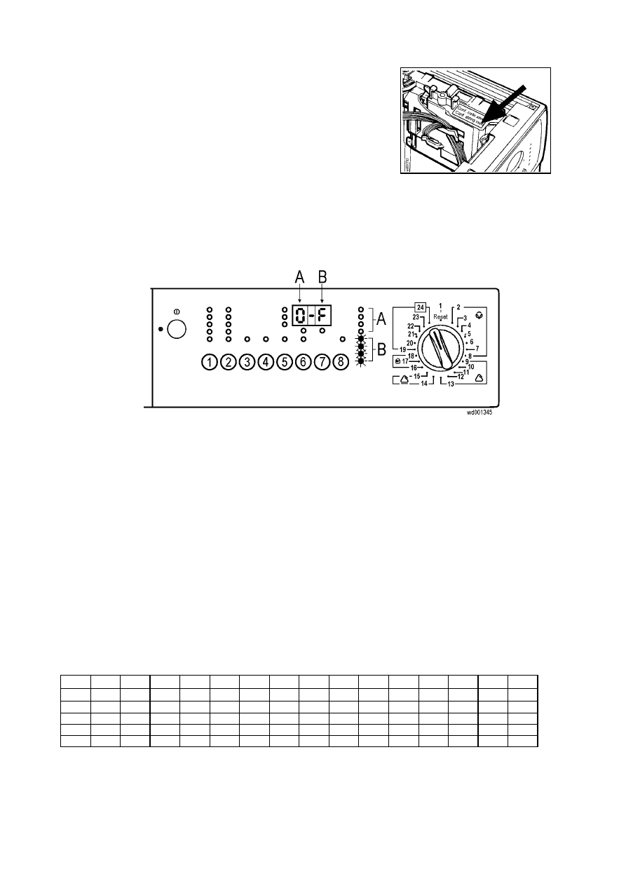
SOI/DT 2002-05 eb
53
599 35 26-84
6.9.1 Configuration code
The configuration code (16 alphanumeric digits) is
shown on a label affixed to the casing of the main
PCB and in the Spare Parts Lists describing the
various models.
It is advisable to note the configuration code on the casing of the
new PCB fitted to the washing machine.
6.9.2 Reading the configuration code
The configuration code is shown, one character at a time, on the display (if featured) or on the washing
phase display LEDs.
A = The first digit shown on the display (if featured) indicates the position of the value to be entered. The
same information is also displayed in binary format on the first four washing phase LEDs.
To
read the various positions, press one of the wash cycle option buttons (the first position displayed is
"0").
B = The last digit on the display (if featured) indicates the value of the configuration character to be
entered in a given position. The same information is also displayed in binary format on the second set
of four washing phase LEDs.
To
modify the value of the character displayed, press the START/PAUSE button.
Binary codes
The table below can be used to convert the binary code shown by the LEDs into the corresponding letter or
decimal number.
0 1 2 3 4 5 6 7 8 9 10 11 12 13 14 15
A b C d E F
❍
❍
❍
❍
❍
❍
❍
❍
●
●
●
●
●
●
●
●
❍
❍
❍
❍
●
●
●
●
❍
❍
❍
❍
●
●
●
●
❍
❍
●
●
❍
❍
●
●
❍
❍
●
●
❍
❍
●
●
❍
●
❍
●
❍
●
❍
●
❍
●
❍
●
❍
●
❍
●
❍
LED
OFF
●
LED
ON
SOI/DT 2002-05 eb
54
599 35 26-84
6.9.3 Example
of
configuration
Configuration code:
A2A7808080E691F2
POSITION:
0 1 2 3 4 5 6 7 8 9 10
A
11
B
12
C
13
D
14
E
15
F
↓
↓
↓
↓
↓
↓
↓
↓
↓
↓
↓
↓
↓
↓
↓
↓
VALUE:
A 2 A 7 8 0 8 0 8 0 E 6 9 1 F 2
Table of cycle phase Leds
On models not featuring the display window, it is advisable, before beginning the configuration procedure, to
convert the digits of the configuration code into binary format (the positions, indicated by the first group of 4
LEDs, are not modified).
0 1 2 3 4 5 6 7 8 9 10 11 12 13 14 15
A b C d E F
❍
❍
❍
❍
❍
❍
❍
❍
●
●
●
●
●
●
●
●
❍
❍
❍
❍
●
●
●
●
❍
❍
❍
❍
●
●
●
●
❍
❍
●
●
❍
❍
●
●
❍
❍
●
●
❍
❍
●
●
PO
SI
T
IO
N
❍
●
❍
●
❍
●
❍
●
❍
●
❍
●
❍
●
❍
●
●
❍
●
❍
●
❍
●
❍
●
❍
●
❍
●
❍
●
❍
❍
❍
❍
●
❍
❍
❍
❍
❍
❍
●
●
❍
❍
●
❍
●
●
●
●
❍
❍
❍
❍
❍
❍
●
●
❍
❍
●
●
❍
❍
❍
●
❍
❍
❍
❍
❍
❍
❍
❍
●
●
●
❍
VA
L
U
E
A 2 A 7 8 0 8 0 8 0 E 6 9 1 F 2
CONFIGURATION
1. Access the diagnostics system.
2. Turn the programme selector clockwise to the last position (24): the code relative to the first of the 16
digits of the configuration code (position 0) is displayed.
3. Press the START/PAUSE button sequentially to enter the letter A in position 0. If the appliance features a
display window, this will show 0-A; if not, the wash cycle LEDs should light as shown in column 0 of the
table (i.e. the fifth and seventh LEDs).
4. Press one of the option buttons (with the exception of START/PAUSE) to pass to the second position,
and enter 2 by pressing START/PAUSE. The display should now show 1-2, and the LEDs should light as
shown in column 1 of the table (fourth and seventh).
5. Repeat this procedure to enter the remaining configuration digits. When all the digits have been entered,
press one of the option buttons (with the exception of START/PAUSE) to check that the configuration
code is correct.
6. Memorize the configuration code by pressing START/PAUSE and one of the option buttons at the same
time for at least 4 seconds, so that the main PCB memorizes the configuration code)
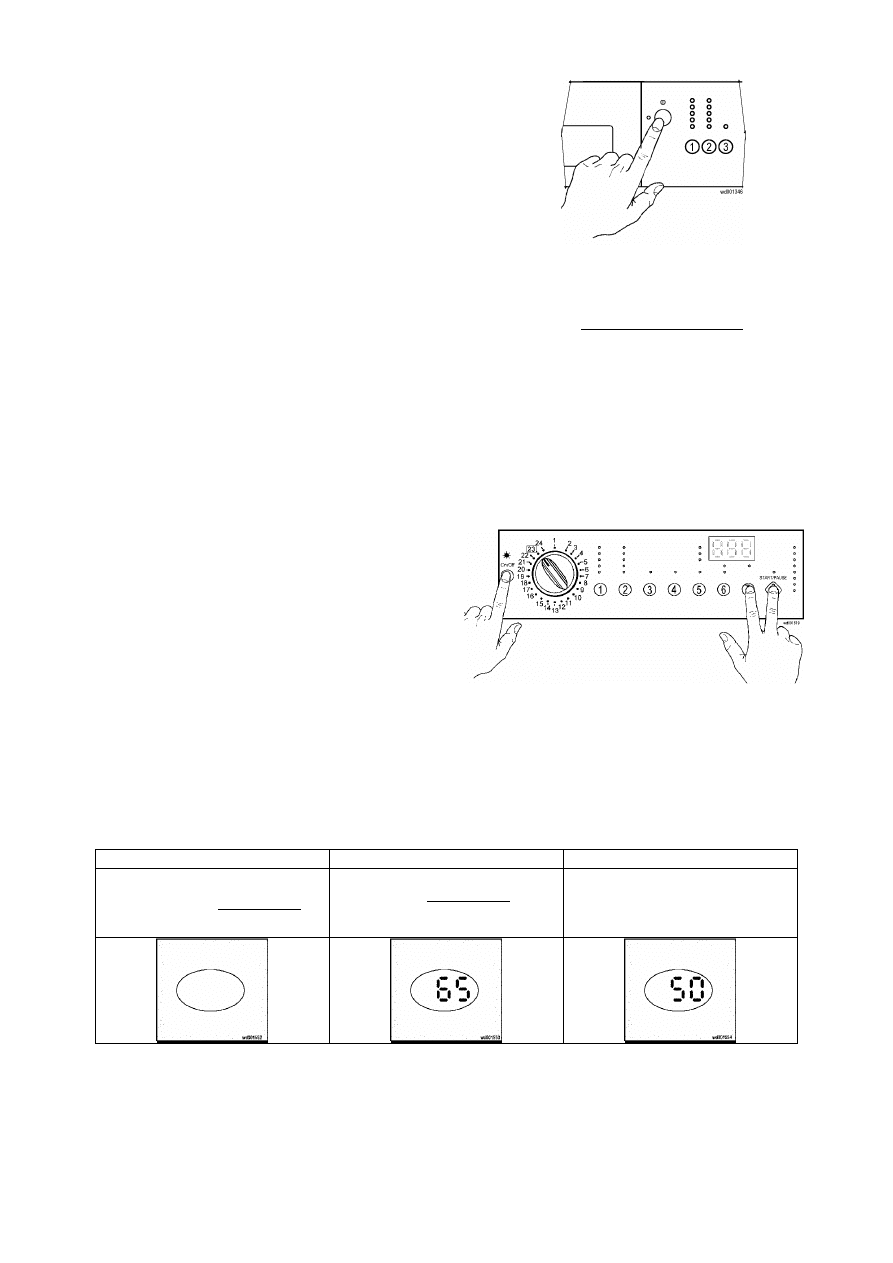
SOI/DT 2002-05 eb
55
599 35 26-84
6.10 Exiting the diagnostics cycle
To exit the diagnostics cycle, switch the appliance off, on,
and then off again.
6.11 Operating time counter
A specific procedure can be used to display the total number of hours of operation of the appliance, which
are counted as from the first time it is operated. This option is available on models with display only. The
maximum value that can be stored in memory is 6,550 hours of operation.
only the time of the normal programmes is counted (cycle diagnostics are not included)
the effective time of the cycles is counted (i.e. not including pauses, delayed start times, rinse hold
periods and the soak phases)
the accuracy of the counter is to within 30 seconds for each programme
only whole hours of operation are displayed (1 hr 59 minutes is displayed as 1 hour
6.11.1 Reading the operating time
Ö
reset the running programme and switch the
appliance off
Ö
turn the programme selector two positions
anti-clockwise (23)
Ö
press simultaneously button START/PAUSE (8)
and any of the option buttons and then, holding
down the buttons, switch the appliance on with
button ON/OFF
Ö
hold down button for at least 4 seconds
Displaying the operating time
The operating time is displayed two digits at a time. The first pair of digits shows the thousands and
hundreds; the second pair shows tens and units.
For example, a total operating time of 6,550 hours will be displayed as follows:
1
→
2
→
3
→
Blank display for two seconds
The first pair of digits is
displayed for two seconds:
- thousands (6)
- hundreds (5)
The second pair of two digits is
displayed for two seconds:
- tens (5)
- units (0)
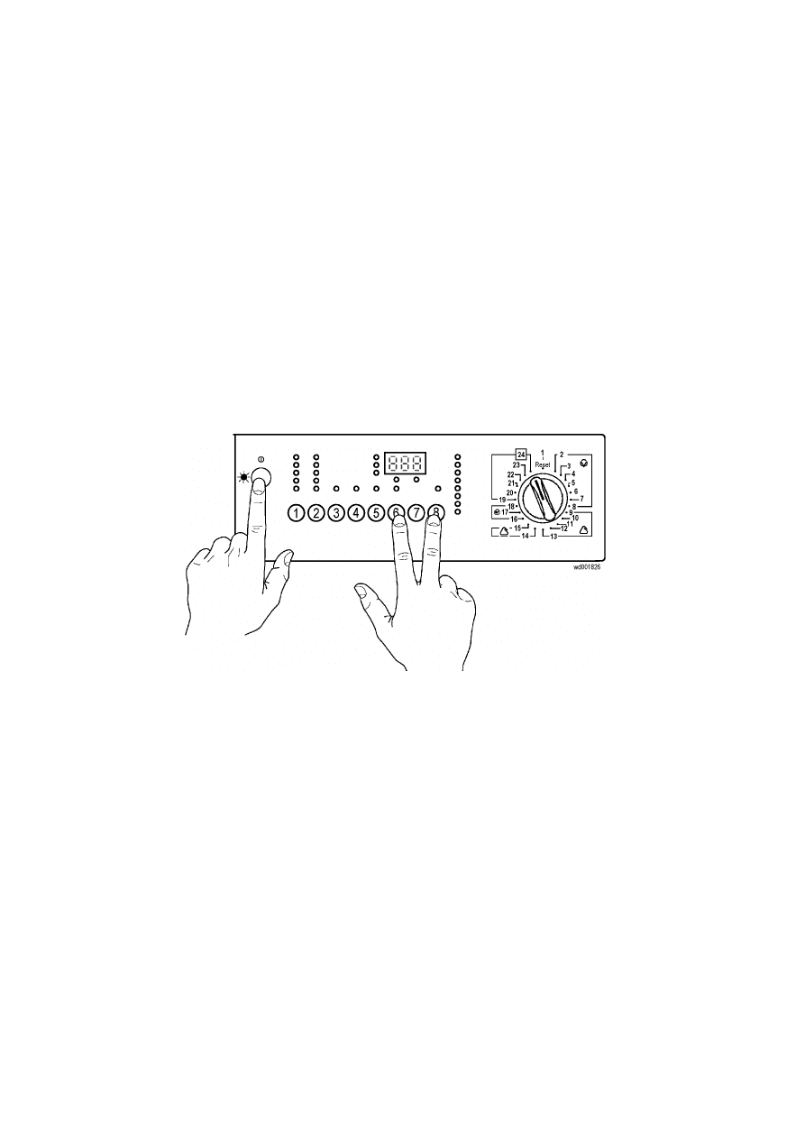
SOI/DT 2002-05 eb
56
599 35 26-84
7 DEMO
Mode
A special cycle has been created for demonstration of the operation of these appliances in retail outlets
without connecting the appliance to the water supply. In this way, the salesman can select any programme;
after starting the cycle by pressing START, the appliance will perform certain phases only, and will skip
those which cannot be performed (water fill, drain, heating).
The cycle takes place as follows:
the door locking device is actioned in the normal way (i.e. the door remains locked while the appliance is
in operation, and can be opened at the end of the cycle or in pause mode)
motor: all low-speed movements are enabled, while the pulse signals and the spin cycle are excluded
the water fill solenoids and the drain pump are disabled
circulation pump (certain models only): this pump is normally disabled, but functions if water is
introduced manually until the anti-boiling safety level has been reached
display: since the phases of the cycle take place in rapid succession (1 second of the demo cycle is
equivalent to 1 minute of the actual cycle), the time-to-elapse decreases by 1 unit per second.
Remember that the time-to-elapse does not always correspond to the actual cycle time
alarms: for reasons of safety, the following groups of alarms remain enabled: E40 (door closed), E50
and E90 (communication between the boards/configuration).
7.1 Setting demo mode
Ö
Reset the running programme and switch the appliance off
Ö
Turn the programme selector one position anticlockwise (24)
Ö
Press simultaneously button START/PAUSE (8) and any of the option buttons and then, holding down
the buttons, switch the appliance on with button ON/OFF
Ö
Press and hold down the buttons for at least 4 seconds
7.2 Exiting demo mode
Switch the appliance off to exit the demo mode.
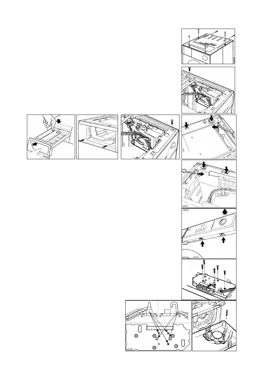
SOI/DT 2002-05 eb
57
599 35 26-84
8 Accessibility to electronic control
8.1 Cover
a. Unscrew ther fixing screws of the metallic panel (1)
b. Push backwards and release it from the cabinet
8.1.1 Main
PCB
a. Remove
the
cover
b. Unscrew the support fixing screw – board housing (2)
c. Release the wiring from the supports
d. Extract the electronic board housing
e. Disconnect the connectors
8.2 Control panel
a. Remove the cover
b. Extract the detergent drawer (3)
c. Unscrew the control panel screws to control support (4)
d. Unscrew front screws support crossbar to cabinet (5)
e. Release the fixing wings (6-7)
f. Raise the support to release the control panel lower wings (8)
g. Disconnect the wiring connector from the display board and remove the
control panel
8.2.1 Control/Display
board
a. Remove the control panel
b. Disconnect the connector and the wiring from the board
c. Unscrew the fixing screws PCB housing-control panel (9)
d. Extract the board-housing assembly
If the control/display board needs to be replaced, before mounting the new
component, cut the 5 plastic hooks on the board housing (10)
8.2.2 Buzzer
a. Remove the control panel
b. Disconnect the wiring connector
c. Release it from the control panel fixing wings
8.2.3 Programme
selector
a. Remove the control panel
b. Disconnect the wiring connector
c. Unscrew the fixing screws to selector and
support (11)
5
3
4
6
7
2
8
1
9
10
11
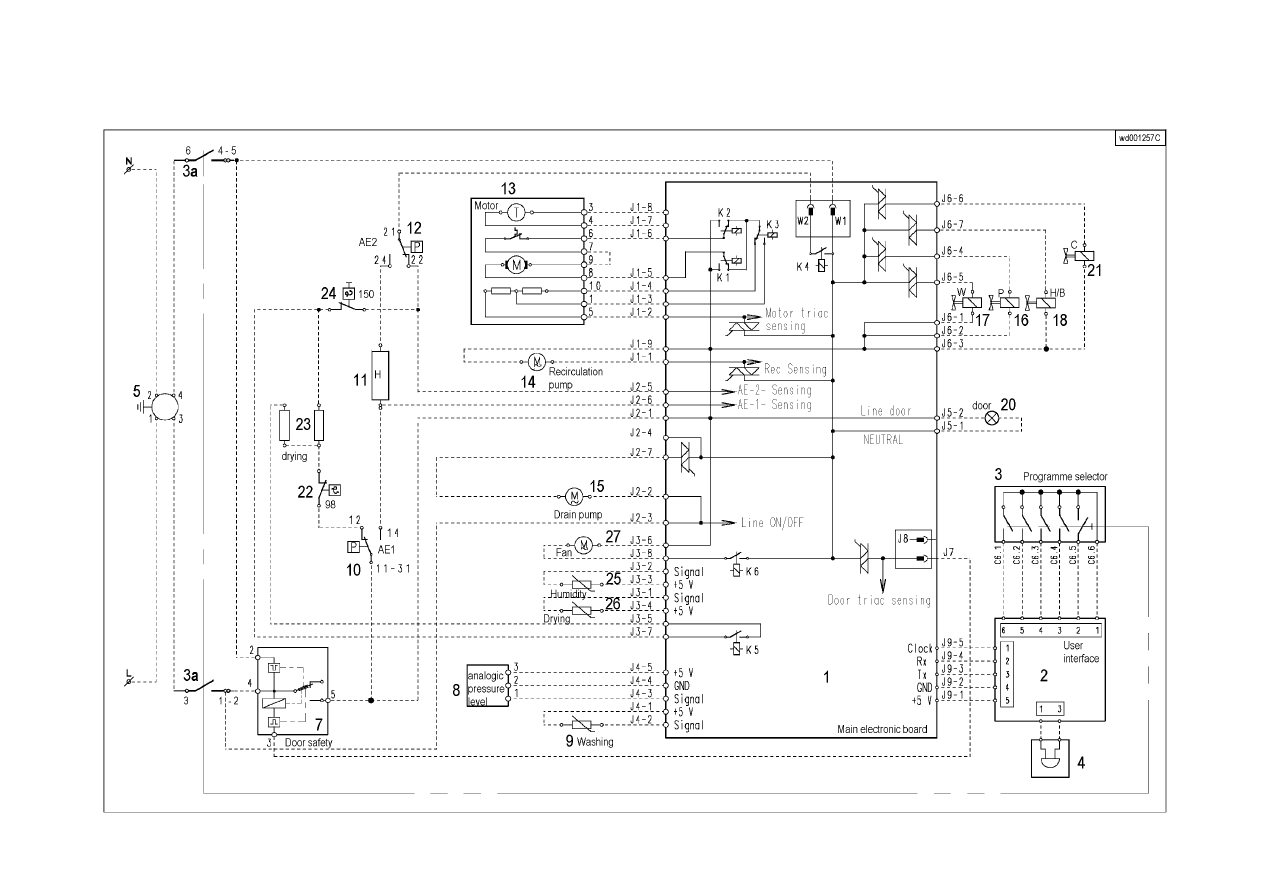
SOI/DT 2002-05 eb
58
599 35 26-84
9 Basic
circuit
diagram
9.1 Version with AC motor
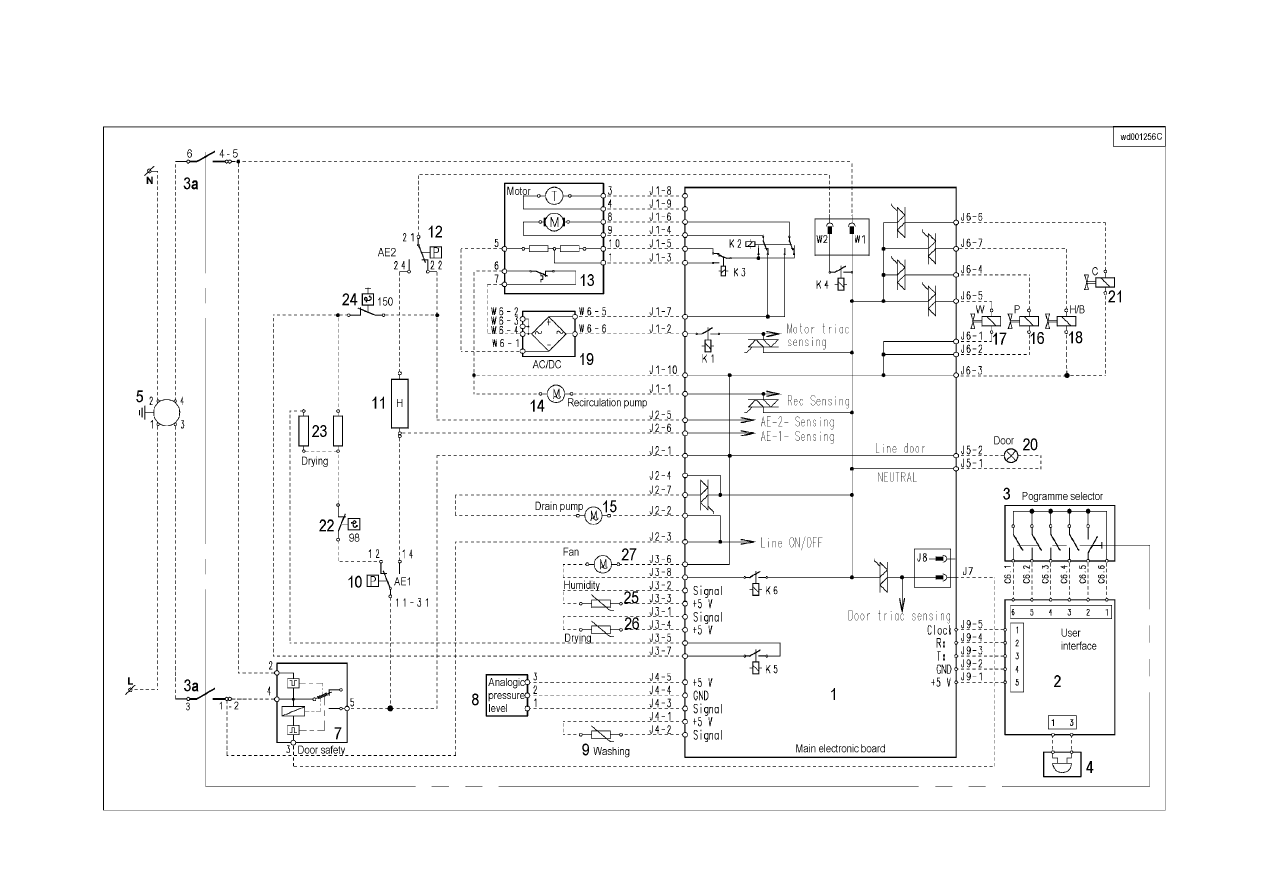
SOI/DT 2002-05 eb
59
599 35 26-84
9.2 Version with DC motor

SOI/DT 2002-05 eb
60
599 35 26-84
9.3 Key to circuit diagram
1. Main PCB
2. Control/display board
3. Programme selector
3a. Main switch
4. Buzzer (certain models only)
5. Anti-interference filter
7. Door interlock
8. Electronic pressure switch
9. NTC temperature sensor (washing)
10. Anti-boiling pressure switch 1
11. Heating element (washing)
12. Anti-boiling pressure switch 2
13. Motor
14. Circulation pump (Jetsystem models)
15. Drain pump
16. Pre-wash solenoid
17. Wash solenoid
18. Bleach solenoid or hot water solenoid
(certain models only)
19. AC/DC Converter (certain models only)
20. Door open lamp
Washer-dryers only:
21. Condensation solenoid
22. Safety thermostat
23. Heating element (drying)
24. Manual-reset safety thermostat
25. NTC temperature sensor (humidity control)
26. NTC temperature sensor (drying)
27. Fan motor
Wyszukiwarka
Podobne podstrony:
hplj 5p 6p service manual vhnlwmi5rxab6ao6bivsrdhllvztpnnomgxi2ma vhnlwmi5rxab6ao6bivsrdhllvztpnnomg
Oberheim Prommer Service Manual
Korg SQ 10 Service Manual
MAC1500 service manual
Kyocera Universal Feeder UF 1 Service Manual
Proview RA783 LCD Service Manual
indesit witp82euy Service Manual
Glow Worm installation and service manual Hideaway 70CF UIS
Proview PZ456 LCD Service Manual
Glow Worm installation and service manual Ultimate 50CF UIS
Glow Worm installation and service manual Ultimate 60CF UIS
Proview SH770I LCD Service Manual
M23 Service Manual
Glow Worm installation and service manual Glow micron 60
Konica Minolta QMS 7115, 7118 Service Manual
Honda NSR125 '87 Service Manual
Epson Stylus Color 460 Service Manual
więcej podobnych podstron