
K128
USB
PICmicro®
Programmer
DIY Electronics (HK) Ltd
PO Box 88458,
Sham Shui Po,
Hong Kong
Last Modified March 31 2003
Board Construction
The board is quite easy to construct but it is advisable to read through these
notes before starting. The USB chip and all other surface mount components
have been premounted to make construction easier.
WARNING
Be aware that the USB chip is sensitive to static electricity discharge and could
be damaged by mishandling of the PCB. Be careful with the board and avoid
touching any of the tracks or pads while assembling it. Try to handle it only by
the edges.
The other chip in this kit is also sensitive to static discharge. This is the
PIC16F628. Do not touch the pins and only handle it by the ends. A socket is
supplied to allow for upgrades and easy assembly.
Starting
The first thing to do is inspect the PCB for shorted or open tracks or other
damage, especially to the premounted components. Be aware of the static
warning when doing this check. When you are satisfied that all is well, then you
can proceed.
ALL COMPONENTS EXCEPT FOR THE LED AND ZIF SOCKET MOUNT ON
THE BOTTOM SIDE OF THE PCB.
Start by mounting the 6MHz crystal. Before soldering it, make sure there is a
small gap (~ 1mm) between it and the PCB. This is to keep the metal can of the
component from shorting its own mounting pads.
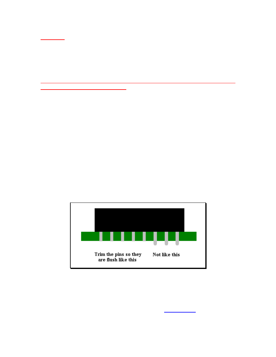
Next, mount the 18 pin IC socket for the PIC16F628 chip. The indented end
faces towards the USB chip. When placing the socket, make sure the pins are
flush with the top of the PCB surface and not protruding above it before
soldering.
Before soldering the USB connector, trim the 4 connector pins and the two
support pins so that these leads are flush with the PCB top surface when
inserted into the PCB.
The pins for the above two components have to be made flush with the PCB top
surface otherwise the extra pin lengths won’t allow the ZIF socket to sit flat on
the PCB surface.
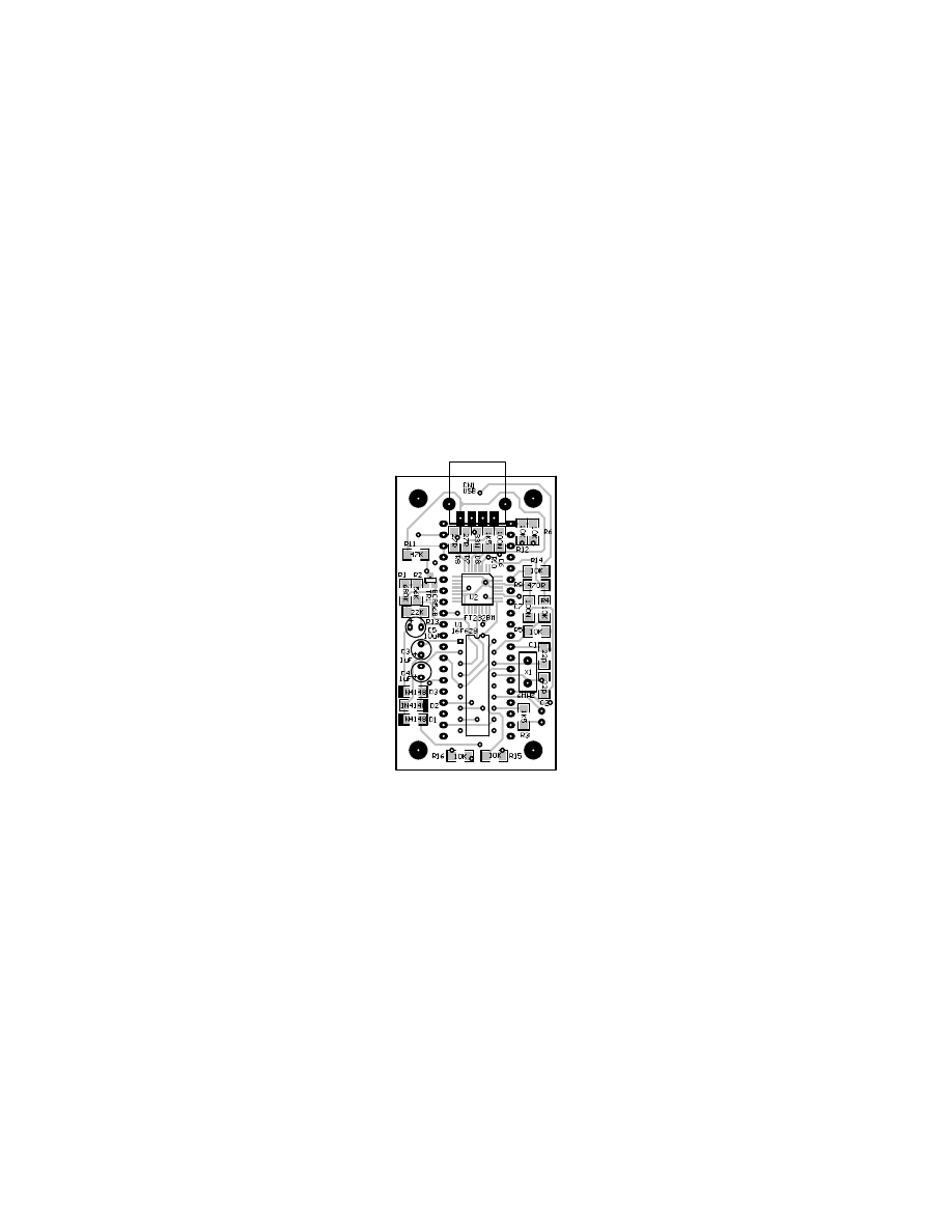
Next, mount all the electrolytic capacitors. These are polarity sensitive
components so make sure they are mounted properly. The positive lead is longer
than the negative lead, and the negative lead is also marked on the side of the
capacitor. On the PCB overlay, there are holes marked [+] as the positive lead
for each of these components. There are 2 x 1uF and 1 x 10uF capacitors so
please try not to get them mixed up. See the
mounting positions.
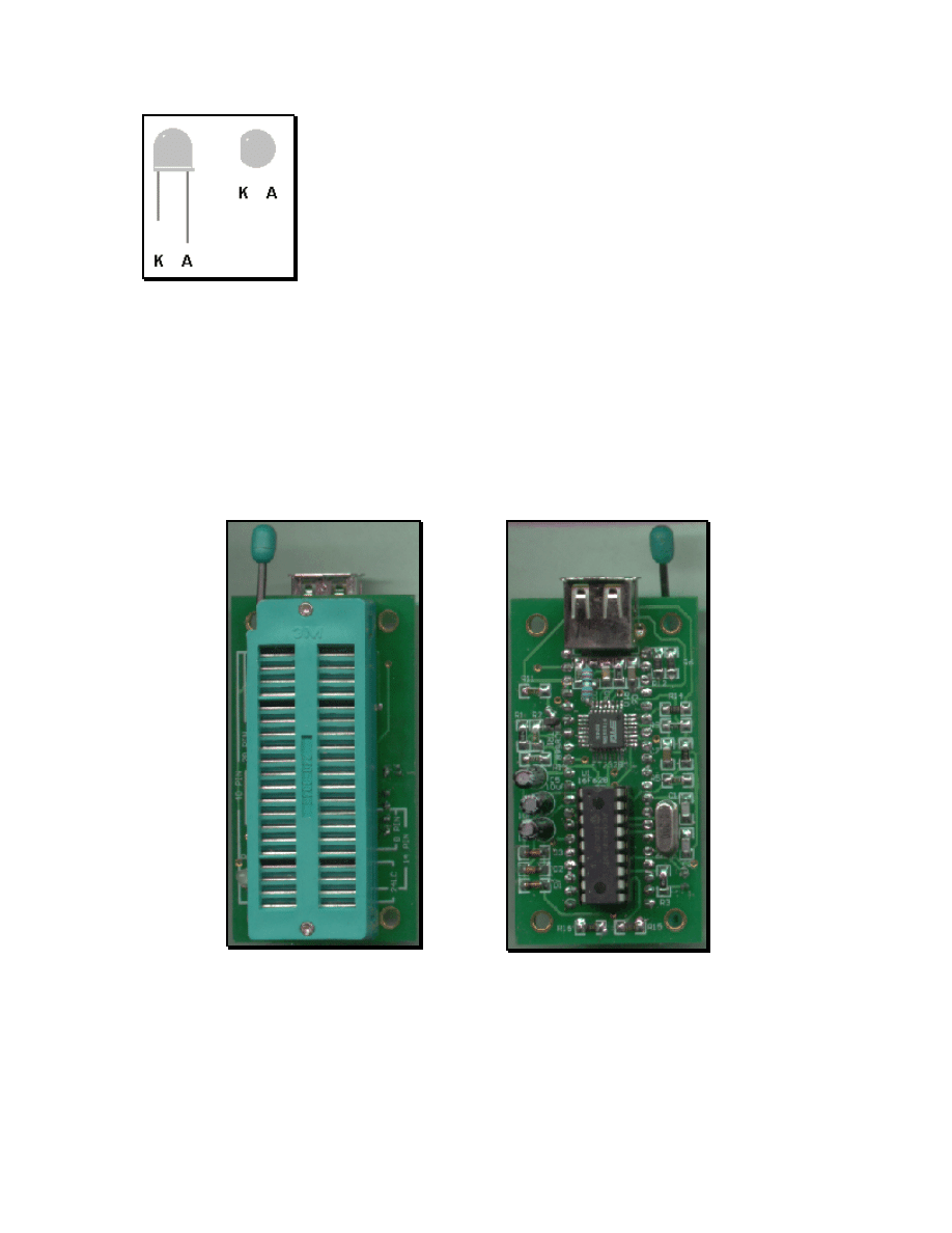
There is one LED that can be mounted next. Make sure it
are oriented correctly and is mounted from the TOP PCB
side. The anode (A) is marked on the PCB and is the longer
of the two leads on the component. The Cathode has a flat
surface on the LED body and is also marked on the board
as (K).
Very carefully check your work at this stage, as the next part to mount is the ZIF
socket. After mounting, this component hides a lot of soldered connections and
will make error corrections very difficult. Inspect the board for dry or unsoldered
joints and check all components for correct orientation and placement.
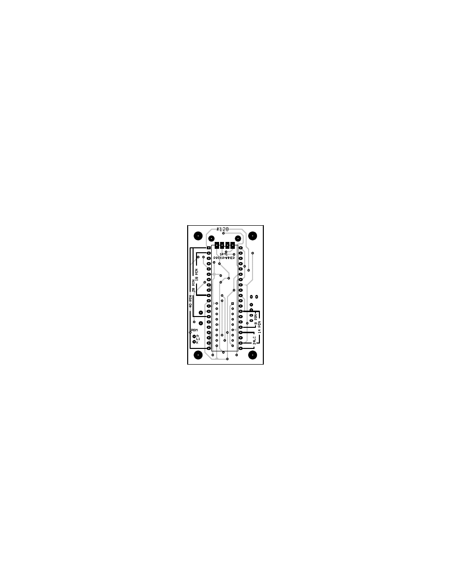
Now insert the preprogrammed PIC16F628 into its socket. Pin 1 is towards the
USB socket. The finished board should look like the images shown here.
This completes the construction phase.

USB Drivers
To enable USB capability for your PC and this project you will need to install a
special driver. This is a piece of software that handles the communications
between the PC and the special USB chip on the programmer PCB.
Create a USB driver sub directory into the directory where your programmer
software was installed. C:\diyprog was the default. Therefore you would have
a new directory called C:\diyprog\usb.
The drivers come in 2 flavours, plug and play support and no plug and play
support. As this programmer does not have plug and play support, that narrows it
down to 1 choice.
You will need to visit this web page and download this driver.
VCP drivers for Win 98/2000/ME/XP (without PNP support)
http://www.ftdichip.com/FTDriver.htm
Download and unzip the file into the newly created USB directory.
Now visit this other web page and download the PDF application note that
describes how to install the driver for your particular system.
http://www.ftdichip.com/FTApp.htm
For example you would download...
AN232-03 for Win 98
AN232-05 for Win2000
Download the PDF file into the USB driver directory listed above.
Open and follow the simple directions given in the PDF file. This should only take
a few minutes to do.
When the driver installation is completed, connect a USB cable from the PC to
the programmer board. This will power the board.
At this stage you may get a message from Windows saying that it has found new
hardware.

Also the LED should flash on and change colors briefly.
If not, monitor and check the PCB components and make sure nothing gets too
hot. If the PIC gets too hot to touch, disconnect the USB cable immediately as
the PIC is most likely inserted the wrong way around. If this is the case, then
they are quite tough little chips and it may have survived. Insert it the correct way
and re-connect the USB cable. If the LED flashed as described earlier then it
should be ok.
Disconnect the cable and insert the PCB into the mounting box provided with the
kit. The PCB will be a nice snug fit and no screws should be necessary to hold it
in place.
which is the Windows® driver interface supplied with the
kit.
Click [File] -> Port or double click the COM x label on screen to bring up
the COM port window. Select the COM port that you selected for use for USB
communications while installing the driver, then OK. If you don’t know what port it
is connected to, click on
START - > Settings -> Control Panel
.
Then double click System.
Look for the Device Manager and go to Ports (COM & LPT).
You will see COM x listed next to the USB label. X will be the COM port number
for you to select in the MicroPro program.
The PC may take a short while to establish communications with the USB port.
When it has done so, the COM port number will appear on screen and the
programmer is ready for use on the USB port.
From MicroPro, make sure that Kit 128 is selected by clicking on
FILE -> Programmer Style -> K128
.
If all is well, as a simple system test, click on
OPTIONS -> Reset Programmer
You should see the LED change color, then stay red. You should also see
Board Connected
appear on the MicroPro message bar.

Now select 16F84 from the chip select menu and click on Read. You should see
the LED change to green while the programmer reads from a non existant chip.
The screen will most likely fill with 0000's or 3FFF’s.
Your new programmer is now ready for use.
When using the USB interface, always connect the
programmer to the PCB before starting MicroPro.exe,
and close MicroPro before disconnecting the
programmer.
Failure to use this power up - power down sequence
may result in a stalled PC for a minute or so because of
the non responding USB port.

PARTS LIST
Used Part Type Designators Description
SEMICONDUCTORS
1
FT232BM
U2
USB Converter
1
PIC16F628
U1
Preprogrammed Microcontroller
3
1N4148
D1, D2, D3
Diode
1
BC856B
TR1
PNP Transistor
1
6MHz
X1
Crystal
1
LED
L1
Bi-Color
RESISTORS all 1206
2
27R
R7, R8
1
470R
R9
2
1K5
R3, R10
7
10K
R4, R5, R6, R12, R14, R15, R16
1
22K
R13
1
47K
R11
1
56K
R2
1
680K
R1
CAPACITORS
2
22p
C1, C2
1206 Ceramic
1
33N
C8
1206 Ceramic
2
100N
C6, C7
1206 Ceramic
2
1uF
C3, C4
16V Electrolytic
1
10uF
C5
50V Electrolytic
MISCELLANEOUS
1
Presoldered PCB
PCB1
1
40 pin ZIF socket
SKT1
1
18pin IC SOCKET
1
UT-5676
CN2
USB Connector
1
Plastic Box
1
2
3
4
5
6
A
B
C
D
6
5
4
3
2
1
D
C
B
A
Title
Number
Revision
Size
C
Date:
31-Mar-2003
Sheet of
File:
C:\DIYPRO~1\PROGRA~1\SCHEMS\K128.SCH
Drawn By:
C1
22p
C2
22p
X1
6MHZ
GND
RA0
17
RA1
18
RA2
1
RA3
2
RA4
3
RB0
6
RB1
7
RB2
8
RB3
9
RB4
10
RB5
11
RB6
12
RB7
13
MCLR
4
OSC1
16
OSC2
15
Gnd
5
VCC
14
U1
16F628
D1
1N4148
D2
1N4148
D3
1N4148
C3
1uF
C4
1uF
C5
10uF
VCC
UTX
R1
680K
R2
56K
VPP
CLOCK
DATA
VccP
L1
PGM
R3
1K5
LEDA
URX
XTAL
GND
R4
10K
R5
10K
C6
100N
R7
27R
R8
27R
R9
470R
R10
1K5
C8
33N
C7
100N
XTAL
VCC
VCC
GND
GND
UTX
URX
GND
USBP
USBM
1
2
3
4
CN1
USB
VCC
GND
USBP
USBM
AVCC
30
VCC
3
VCC
13
VCC
26
USBDP
7
USBDM
8
3V3OUT
6
XTIN
27
XTOUT
28
TEST
31
RESET#
4
EECS
32
EESK
1
EEDATA
2
RSTOUT#
5
AGND
29
GND
9
GND
17
SLEEP#
10
RXLED#
11
TXLED#
12
PWRCTL
14
PWREN#
15
TXDEN
16
RI#
18
DCD#
19
DSR#
20
DTR#
21
CTS#
22
RTS#
23
RXD
24
TXD
25
U2
FT232BM
GND
MCLR
R6
10K
MCLR
R11
47K
LEDK
LEDK
Vprg
Vprg
R13
22K
LEDA
TR1
BC856B
R12
10K
1
2
3
4
5
6
7
8
9
10
11
12
13
14
15
16
17
18
19
20
21
22
23
24
25
26
27
28
29
30
31
32
33
34
35
36
37
38
39
40
SKT1
PROGRAMMER
R15
10K
R14
10K
DATA
DATA
DATA
CLOCK
CLOCK
CLOCK
VPP
GND
GND
GND
GND
GND
CLOCK
VccP
VccP
VccP
VccP
VccP
GND
DATA
R16
10K
VccP
GND
GND
GND
GND
GND
GND
GND
Document Outline
- Board Construction
- Driver Info
- Parts List
- Schematic
- PCB Top Overlay
- PCB Bottom Overlay
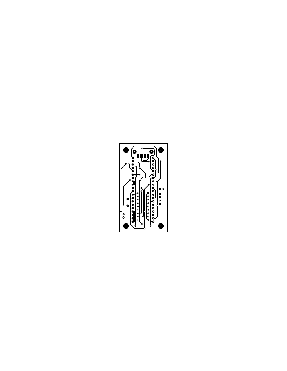
- PCB Top
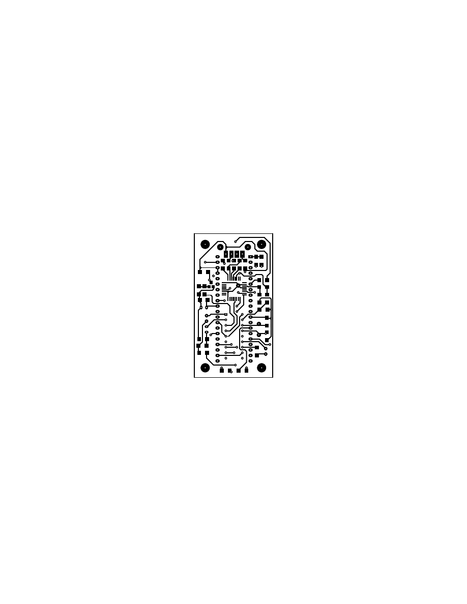
- PCB Bottom
Wyszukiwarka
Podobne podstrony:
mechanika budowli II analiza ki Nieznany
Program kola plastycznego id 39 Nieznany
PROGRAM AKT PRAWA MIEJSCOW PWS Nieznany
Programowanie Windows 95 dla ch Nieznany
programowanie c pl v1 id 395919 Nieznany
Programowanie w Unix p1 id 8273 Nieznany
02 NoZ def model zarzadzanie ki Nieznany
Programy i Fundusze UE part2 id Nieznany
PrAdmin program cw 2011 id 3845 Nieznany
Program Z D 1112 EK id 395574 Nieznany
animacja flash tworzenie stron Nieznany
Programowanie Od podstaw id 39 Nieznany
00 Program nauki Krawiec 743 01 Nieznany
program uzbrojenia 12 lipca id Nieznany
Program cwiczen 2013 id 395015 Nieznany
więcej podobnych podstron