M
M
M
M
M
M
M
M
M
M
M
M
M
M
Ground Fault
Protection
E
68
12
4
L
ow
V
ol
ta
ge
E
xp
er
t
G
u
id
es
N
°
2

1
Contents
1. The Role of “Ground Fault Protection” ............................... 3
1.1. Safety and Availability ........................................................................ 3
1.2. Safety and Installation Standards ....................................................... 4
- 1.2.1. The IEC 60 364 Standard ....................................................... 4
- 1.2.2. The National Electric Code (NEC) ........................................ 7
1.3. The Role and Functions of “Ground Fault Protection” ...................... 9
- 1.3.1. Earthing System .................................................................... 9
- 1.3.2. RCD and GFP ....................................................................... 9
2. The GFP Technique ............................................................ 10
2.1. Implementation in the Installation .................................................... 10
2.2. GFP Coordination .............................................................................
12
- 2.2.1. Discrimination between GFP Devices .................................. 12
- 2.2.2. Discrimination between upstream GFP Devices and
downstream SCPDs .......................................................................... 13
- 2.2.3. ZSI Logical Discrimination .................................................... 14
2.3. Implementing GFP Coordination ....................................................... 15
- 2.3.1. Application Examples ........................................................... 15
2.4. Special Operations of GFP
Devices ................................................. 16
- 2.4.1. Protecting Generators ........................................................ 16
- 2.4.2. Protecting Loads .................................................................. 17
- 2.4.3. Special Applications ............................................................ 17
3. GFP Implementation ........................................................... 18
3.1. Installation Precautions ....................................................................
18
- 3.1.1. Being sure of the Earthing System ..................................... 18
- 3.1.2. Being sure of the GFP Installation ....................................... 18
3.2. Operating Precautions ......................................................................
20
- 3.2.1. Harmonic Currents in the Neutral conductor ........................ 20
- 3.2.2. Incidences on GFP Measurement ........................................ 21
3.3. Applications ........................................................................................ 22
- 3.3.1. Methodology ........................................................................ 22
- 3.3.2. Application: Implementation in a Single-source
TN-S System .................................................................................... 22
- 3.3.3. Application: Implementation in a Multisource
TN-S System ...................................................................................... 23
4. Study of Multisource Systems .......................................... 24
4.1. A Multisource System with a Single Earthing .................................... 24
- 4.1.1. Diagram 2 ............................................................................ 24
- 4.1.2. Diagrams 1 and 3 ................................................................. 28
4.2. A Multisource System with Several Earthings ................................... 30
- 4.2.1. System Study ........................................................................ 30
- 4.2.2. Solutions .............................................................................. 31
5. Conclusion ........................................................................... 34
5.1. Implementation .................................................................................. 34
5.2. Wiring Diagram Study ....................................................................... 34
- 5.2.1. Single-source System ........................................................... 34
- 5.2.2. Multisource / Single-ground System .................................. 35
- 5.2.3. Multisource / Multiground System ....................................... 35
5.3. Summary Table .................................................................................. 36
- 5.3.1. Depending on the Installation System ................................ 36
- 5.3.2. Advantages and Disadvantages
depending on the Type of GFP .......................................................... 36
6. Installation and implementation of GFP solutions ............. 37

2

3
The Role of “Ground Fault
Protection”
For the user or the operator, electrical power supply must be:
■
risk free (safety of persons and goods)
■
always available (continuity of supply).
These needs signify:
■
in terms of safety, using technical solutions to prevent the risks that are caused
by insulation faults.
These risks are:
❏
electrification (even electrocution) of persons
❏
destruction of loads and the risk of fire.
The occurrence of an insulation fault in not negligible. Safety of electrical
installations is ensured by:
- respecting installation standards
- implementing protection devices in conformity with product standards (in
particuliar with different IEC 60 947 standards).
■
in terms of availability, choosing appropriate solutions.
The coordination of protection devices is a key factor in attaining this goal.
In short
1.1. Safety and Availability
The requirements for electrical
energy power supply are:
■
safety
■
availability.
Installation standards take these 2
requirements into consideration:
■
using techniques
■
using protection specific
switchgears to prevent insulation
faults.
A good coordination of these two
requirements optimizes solutions.
4
L1
L2
L3
N
PE
L1
L2
L3
PEN
The IEC 60 364 standard defines 3
types of Earthing Systems (ES):
■
TN system
■
TT system
■
IT system.
ES characteristics are:
■
an insulation fault has varying
consequences depending on the
system used:
❏
fault that is dangerous or not
dangerous for persons
❏
strong or very weak fault current.
■
if the fault is dangerous, it must be
quickly eliminated
■
the PE is a conductor.
The TT system combined with
Residual Current Devices (RCD)
reduces the risk of fire.
Defined by installation standards, basic principles for the protection of
persons against the risk of electrical shocks are:
■
the earthing of exposed conductive parts of equipment and electrical loads
■
the equipotentiality of simultaneously accessible exposed conductive parts that
tend to eliminate touch voltage
■
the automatic breaking of electric power supply in case of voltage or dangerous
currents caused by a live insulation fault current.
1.2.1. The IEC 60 364 Standard
Since 1997, IEC 364 is identified by a no.: 60 XXX, but its content is exactly the
same.
1.2.1.1. Earthing Systems (ES)
The IEC 60 364 standard, in § 3-31 and 4-41, has defined and developed 3 main
types of Earthing Systems (ES). The philosophy of the IEC standard is to take into
account the touch voltage (Uc) value resulting from an insulation fault in each of the
systems.
1/ TN-C and TN-S systems
■
characteristics:
❏
an insulation fault creates a dangerous touch voltage: it must be instantaneously
eliminated
❏
the insulation fault can be compared to a Phase-Neutral short-circuit
(Id = a few kA)
❏
fault current return is carried out by a PE conductor. For this reason, the fault loop
impedance value is perfectly controlled.
Protection of persons against indirect contact is thus ensured by Short-Circuit
Protection Devices (SCPD). If the impedance is too great and does not allow the
fault current to incite protection devices, it may be necessary to use Residual
Current Devices (RCD) with low sensitivity (LS >1 A).
Protection of goods is not “naturally” ensured.
The insulation fault current is strong.
Stray currents (not dangerous) may flow due to a low PE - Neutral transformer
impedance.
In a TN-S system, the installation of RCDs allows for risks to be reduced:
❏
material destruction (RCD up to 30 A)
❏
fire (RCD at 300 mA).
But when these risks do exist, it is recommended (even required) to use a TT
system.
1.2. Safety and Installation Standards
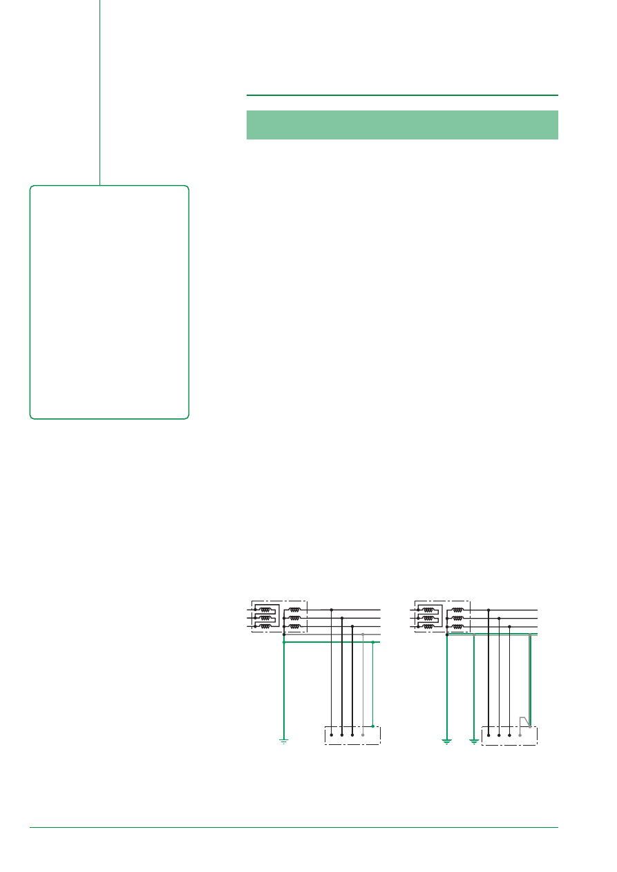
Diagram 1a - “TN-S system”
E51122
Diagram 1b - “TN-C system”
E51123
In short
5
L1
L2
L3
N
PE
L1
L2
L3
N
PE
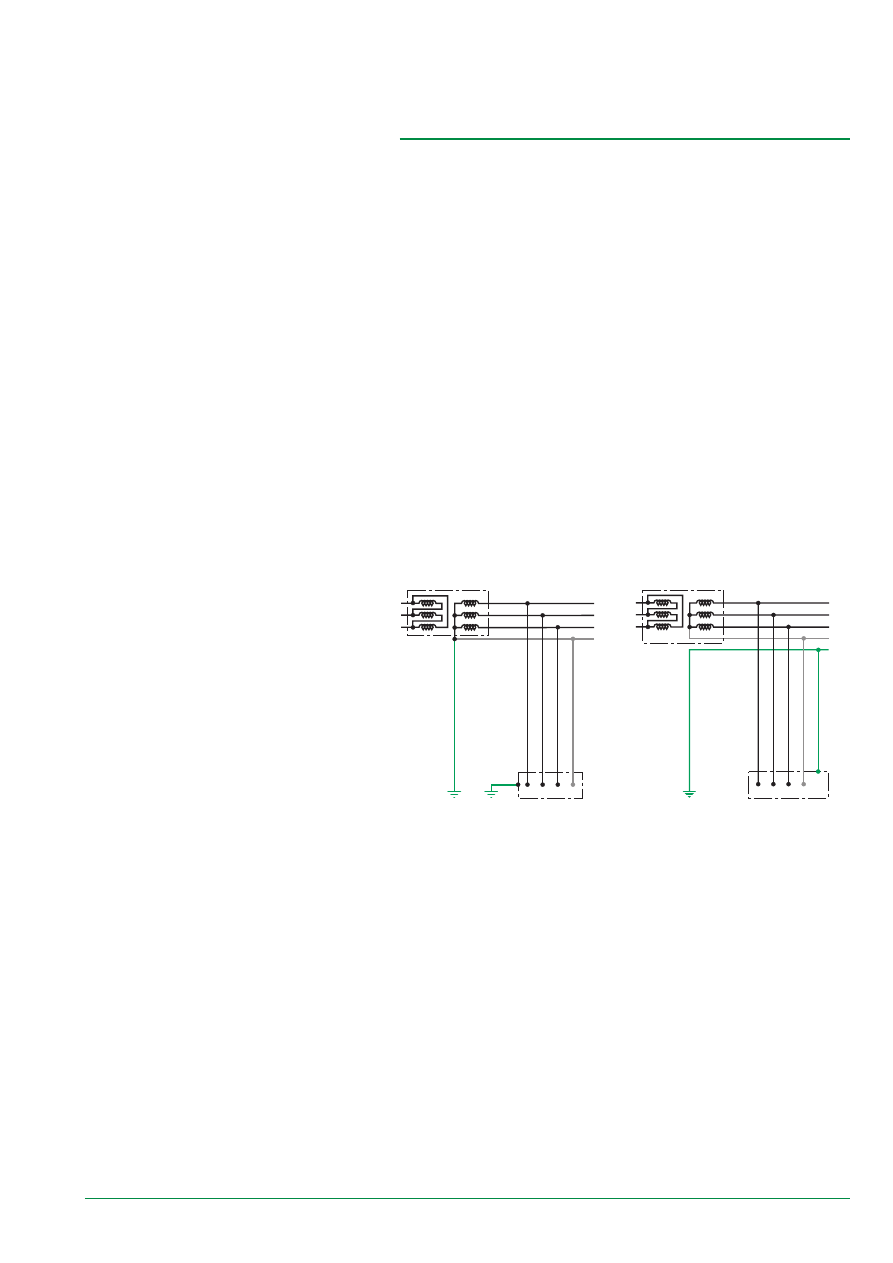
Diagram 2 - “TT system”
E51174
E51175
2/ TT system
■
characteristics:
❏
an insulation fault creates a dangerous touch voltage: it must be instantaneously
eliminated
❏
a fault current is limited by earth resistance and is generally well below the setting
thresholds of SCPDs (Id = a few A).
Protection of persons against indirect contact is thus ensured by an RCD with
medium or low sensitivity. The RCD causes the deenergizing of switchgear as soon
as the fault current has a touch voltage greater than the safety voltage Ul.
Protection of goods is ensured by a strong natural fault loop impedance (some
W
).
The installation of RCDs at 300 mA reduces the risk of fire.
3/ IT system
■
characteristics:
❏
upon the first fault (Id
£
1 A), the voltage is not dangerous and the installation can
remain in service
❏
but this fault must be localised and eliminated
❏
a Permanent Insulation Monitor (PIM) signals the presence of an insulation fault.
Protection of persons against indirect contact is naturally ensured (no touch
voltage).
Protection of goods is naturally ensured (there is absolutely no fault current due to
a high fault loop impedance).
When a second fault occurs before the first has been eliminated, the installation’s
behaviour is analogue to that of a TN system (Id
»
20 kA) or a TT system (Id
»
20 A)
shown below.
Diagram 3 - “IT system”
6
1.2.1.2. Protection using an RCD
RCDs with a sensitivity of 300 mA up to 30 A must be used in the TT system.
Complementary protection using an RCD is not necessary for the TN or IT systems
in which the PE is carried out using a conductor.
For this reason, the type of protection using an RCD must be:
■
High Sensitivity (HS) for the protection of persons and against fire
(30 mA / 300 mA)
■
Low Sensitivity (LS) up to 30 A for the protection of belongings.
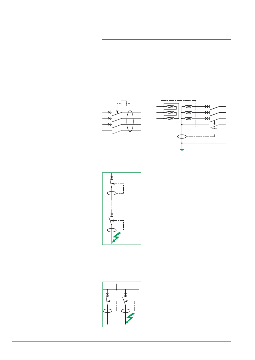
This protection can be carried out by using specific measuring toroids that cover all
of the live conductors because currents to be measured are weak.
At the supply end of an installation, a system, which includes a toroid that measures
the current in the PE, can even be carried out using High Sensitivity RCDs.
downstream
RCD
upstream
RCD
RCD
2
RCD
1
R
R
L1
L2
L3
N
R
L1
L2
L3
N
PE
L1
L2
L3
N
PE
R
RCD Coordination
The coordination of RCD earth leakage functions is carried out using discrimination
and/or by selecting circuits.
E51127
E51126
Diagram 4a
E51124
E54395
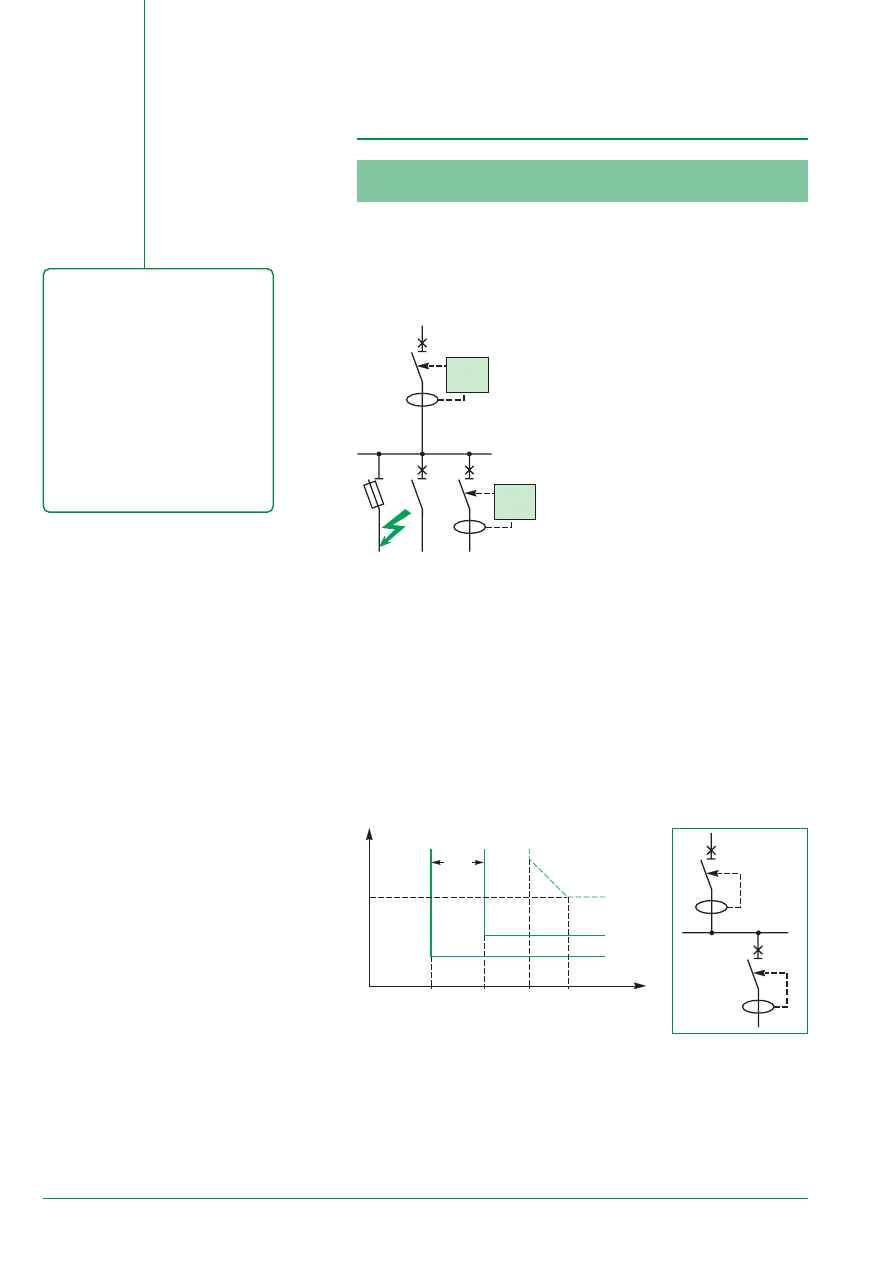
1/ Discrimination consists in only tripping the earth
leakage protection device located just upstream from
the fault. This discrimination can be at three or four
levels depending on the installation; it is also called
“vertical discrimination”. It should be both current
sensitive and time graded.
■
current discrimination.
The sensitivity of the upstream device should be at
least twice that of the downstream device.
In fact, IEC 60755 and IEC 60947-2 appendix B
product standards define:
❏
non tripping of the RCD for a fault current equal to
50 % of the setting threshold
❏
tripping of the RCD for a fault current equal to 100 %
of the setting threshold
❏
standardised setting values (30, 100, 300 mA
and 1 A).
■
time graded discrimination.
RCDs do not limit fault current. The upstream RCD thus has an intentional delay
that allows the downstream RCD to eliminate the fault independently.
Setting the upstream RCD’s time delay should:
❏
take into account the amount of time the circuit is opened by the downstream RCD
❏
not be greater than the fault elimination time to ensure the protection of persons
(1s in general).
2) circuit selection consists in subdividing the circuits
and protecting them individually or by group. It is also
called “horizontal discrimination” and is used in final
distribution.
In horizontal discrimination, foreseen by installation
standards in certain countries, an RCD is not
necessary at the supply end of an installation.
7
The National Electrical Code
(NEC) defines an ES of the TN-S
type
■
non-broken Neutral conductor
■
PE “conductor” made up of cable
trays or tubes.
To ensure the protection of
belongings and prevent the risk of
fire in an electrical installation of this
type, the NEC relies on techniques
that use very low sensitivity RCDs
called GFP devices.
GFP devices must be set in the
following manner:
■
maximum threshold (asymptote)
at 1200 A
■
response time less than 1s for a
fault of 3000 A (setting of the
tripping curve).
1.2.2. The National Electric Code (NEC)
1.2.2.1. Implementing the NEC
§ 250-5 of the NEC defines earthing systems of the TN-S* and IT type*, the latter
being reserved for industrial or specific tertiary (hospitals) applications. The TN-S
system is therefore the most used in commonplace applications.
* TN-S system is called S.G. system (Solidely Grounded) and IT system is called
I.G. system (Insuladed Grounding).
■
essential characteristics of the TN-S system are:
❏
the Neutral conductor is never broken
❏
the PE is carried out using a link between all of the switchgear’s exposed
conductive parts and the metal parts of cable racks: in general it is not a conductor
❏
power conductors can be routed in metal tubes that serve as a PE
❏
earthing of the distribution Neutral is done only at a single point - in general at the
point where the LV transformer’s Neutral is earthed - (see 250-5 and -21)
❏
an insulation fault leads to a short-circuit current.
In short
N
Diagram 6 - “NEC system”
E51128
Protection of persons against indirect contact is ensured:
■
using RCDs in Power distribution because an insulation fault is assimilated with a
short-circuit
■
using High Sensitivity RCD devices (1
D
n =10 mA) at the load level.
Protection of belongings, studies have shown that global costs figure in billions of
dollars per year without using any particular precautions because of:
■
the possibility of strong stray current flow
■
the difficultly controlled fault loop impedance.
For this reason, the NEC standard considers the risk of fire to be high.
§ 230 of the NEC thus develops a protection technique for “fire” risks that is
based on the use of very low sensitivity RCDs. This technique is called GFP
“- Ground Fault Protection”. The protection device is often indicated by GFP”.
■
§ 230.95 of the NEC requires the use of a GFP device at least at the supply end
of a LV installation if:
❏
the Neutral is directly earthed
❏
150 V < Phase-to-Neutral voltage < 600 V
❏
I
Nominal
supply end device > 1000 A.
■
the GFP device must be set in the following manner:
❏
maximum threshold (asymptote) at 1200 A
❏
response time less than 1s for a fault of 3000 A (setting of the tripping curve).
Even though the NEC standard requires a maximum threshold of 1200 A, it
recommends:
❏
settings around 300 to 400 A
❏
on the downstream outgoer, the use of a GFP device that is set (threshold, time
delay) according to the rules of discrimination in paragraph 2.2.
■
exceptions for the use of GFP device are allowed:
❏
if continuity of supply is necessary and the maintenance personel is well trained
and omnipresent
❏
on emergency set generators
❏
for fire fighting circuits.
8
1.2.2.2. Protection using GFP Devices
GFP as in NEC § 230.95
These functions are generally built into an SCPD (circuit-breaker).
Three types of GFP are possible depending on the measuring device installed:
■
“Residual Sensing” RS
The “insulation fault” current is calculated using the vectorial sum of currents of
instrument CT* secondaries .
*The CT on the Neutral conductor is often outside the circuit-breaker.
R
L1
L2
L3
N
R
L1
L2
L3
N
PE
R
L1
L2
L3
N
PE
R
L1
L2
L3
N
E51129
E51125
■
“Source Ground Return” SGR
The “insulation fault current” is measured in the Neutral - Earth link of the LV
transformer. The CT is outside of the circuit-breaker.
E54515
■
“Zero Sequence” ZS
The “insulation fault” is directly calculated at the primary of the CT using the
vectorial sum of currents in live conductors. This type of GFP is only used with weak
fault current values.
Diagram 7a - “RS system”
Diagram 7b - “SGR system”
1.2.2.3. Positioning GFP Devices in the Installation
GFP devices are used for the Protection against the risk of fire.
type/installation
main-distribution
sub-distribution
comments
level
Source Ground Return
❑
used
(SGR)
Residual sensing (RS)
❑
■
often used
(SGR)
Zero Sequence
❑
■
rarely used
(SGR)
❑
possible
■
recommended or required
Diagram 7c - “ZS system”
9
1200 A
250 A
100 A
30 A
Residual Sensing
Source Ground
Zero Sequence
GFP
Type
Thresholds
RCD
using CT
using CT
using relay/zero sequence
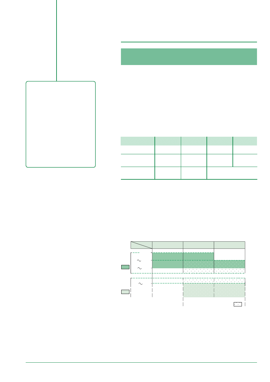
Earthing System
TN-C
TN-S
TT
IT-1st fault
System
System
System
System
fault current
strong
strong
medium
weak
Id
O
20 kA
Id
O
20 kA
Id
O
20 A
Id
O
0,1 A
use of ES
■
IEC 60 364
❏
❏ ❏ ❏
❏ ❏
❏
■
NEC
forbidden
❏ ❏ ❏
forbidden
❏
fire :
■
for IEC 60 364
not recommended not recommended recommended + RCD 300 mA
■
for NEC
not applicable
GFP 1200 A
not applicable
❏
rarely used
❏ ❏
used
❏ ❏ ❏
often used
1.3.2. RCD and GFP
The insulation fault current can:
■
either, cause tripping of Short-Circuit Protection Devices (SCPD) if it is equivalent
to a short-circuit
■
or, cause automatic opening of circuits using specific switchgear:
❏
called RCD if the threshold setting value has High Sensitivity (HS) 30 mA or Low
Sensitivity (LS) up to 30 A
❏
called GFP for very Low Sensitivity setting values (> 100 A).
To ensure protection against fire:
■
the NEC defines the use of an RCD
with very Low Sensitivity called GFP
■
IEC 60 364 standard uses the
characteristics of the TT system
combined with Low or High Sensitivity
RCDs.
These protections use the same
principle: fault current measurement
using:
■
a sensor that is sensitive to earth fault
or residual current (Earth fault current)
■
a measuring relay that compares the
current to the setting threshold
■
an actuator that sends a tripping order
to the breaking unit on the monitored
circuit in case the threshold setting has
been exceeded.
1.3. The Role and Functions
of “Ground Fault Protection”
This type of protection is defined by the NEC (National Electrical Code) to ensure
protection against fire on electrical power installations.
1.3.1. Earthing System
IEC standard:
■
uses ES characteristics to manage the level of fault currents
■
for this reason, only recommends fault current measuring devices that have very
weak setting values (RCD with threshold, in general, < 500 mA).
The NEC:
■
defines TN-S and IT systems
■
recommends fault current protection devices with high setting values (GFP with
threshold, in general, > 500 A) for the TN-S system.
E55262
In short

10
The GFP Technique
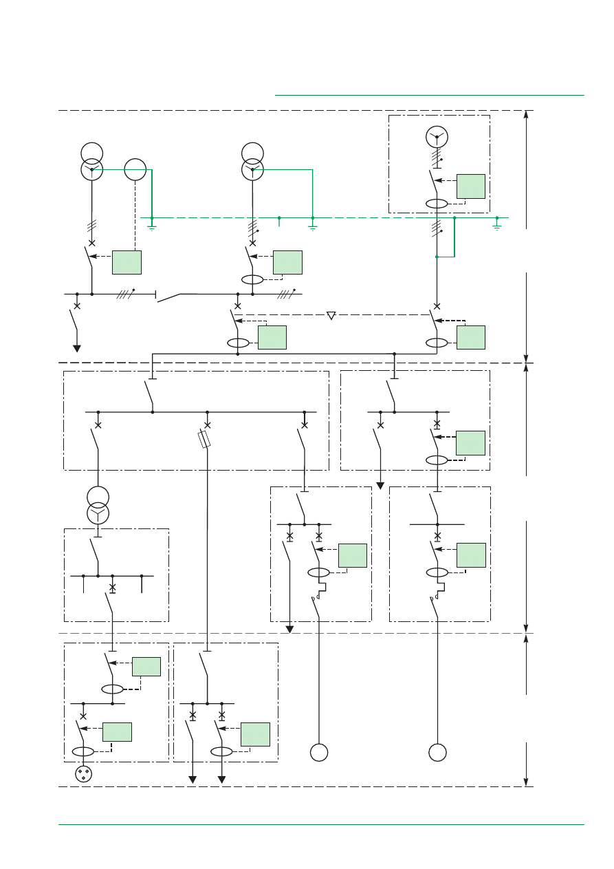
Analysis of diagram 8 shows three levels.
A/ At the MSB level, installation characteristics include:
■
very strong nominal currents (> 2000 A)
■
strong insulation fault currents
■
the PE of the source protection is easily accessible.
For this reason, the GFP device to be placed on the device’s supply end is of the
Residual Sensing or Source Ground Return type.
The continuity of supply requires total discrimination of GFP protection devices in
case of downstream fault.
At this level, installation systems can be complex: multisource, etc.
Managment of installed GFP devices should take this into account.
2.1. Implementation in the Installation
In short
Implementating GFP
The measurement should be taken:
■
either, on all of the live conductors
(3 Phases + Neutral if it is
distributed).
GFP is of the RS or Z type.
■
or, on the PE conductor. GFP is of
the SGR type.
Low Sensitivity GFP can only
operate in the TN-S system.
B/ At the intermediate or sub-distribution switchboard, installation characteristics
include:
■
high nominal currents (from 100 A to 2000 A)
■
medium insulation fault currents
■
the PEs of protection devices are not easily accessibles.
For this reason, GFP devices are of the Residual or Zero Sequence type (for their
weak values).
Note: discrimination problems can be simplified in the case where insulation
transformers are used.
C/ At the load level, installation charecteristics include:
■
weak nominal currents (< 100 A)
■
weak insulation fault currents
■
the PEs of protection devices are not easily accessible.
Protection of belongings and persons is carried out by RCDs with HS or LS
thresholds.
The continuity of supply is ensured:
■
using horizontal discrimination at the terminal outgoer level: an RCD on each
outgoer
■
using vertical discrimination near the protection devices on the upstream sub-
distribution switchboard (easily done because threshold values are very different).
11
Diagram 8 - “general system”
E51131
M
M
RCD
30 mA
RCD
300 mA
ZS
3 A
100 ms
ZS
100 A
100 ms
SGR
1200 A
400 ms
RS
1200 A
400 ms
RS
1200 A
400 ms
RS
400 A
200 ms
Masterpact
M16T
Masterpact
M32T
Masterpact
M16T
Compact
NS100
D25
RS
400 A
Inst
M32W
ZS
30 A
Inst
CB
NS160
MA
ZS
3 A
100 ms
Compact
NS400
D400
M32NI
2000 kVA
2000 kVA
1000 kVA
gI 100
decoupling
transformer
sensitive
motors
motors placed
at a distance
Level B
Level A
Level C
1000 A
to
> 4000 A
100 A
to
2000 A
< 100 A
SMSB
submain-
switchboard
receivers
or terminal
switchboard
MSB
main-
switchboard
12
I
T
30 %
3000 A
1s
3000 A
1200 A
step 1
step 2
downstream
GFP 2
upstream
GFP 1
I down-
stream
I up-
stream
2
1
up-
stream
GFP
down-
stream
GFP
2.2. GFP Coordination
The NEC 230 § 95 standard only requires Ground Fault protection using a GFP
device on the supply end device to prevent the risk of fire.
However, insulation faults rarely occur on MSB busbars, rather more often on the
middle or final part of distribution.
Only the downstream device located just above the fault must react so as to avoid
deenergisation of the entire installation.
Discrimination between Ground
Fault Protection Devices must be
current sensing and time graded.
This discrimination is made
between:
■
upstream GFP and downstream
GFP devices
■
upstream GFP devices and short
delay tripping of downstream
devices.
“ZSI” logic discrimination guarantees
the coordination of upstream and
downstream devices. It requires a
pilot wire between devices.
E51133
2.2.1. Discrimination between GFP Devices
Discrimination Rules: discrimination is of the current sensing and time
graded type
These two types of discrimintation must be simultaneously implemented.
■
current sensing discrimination
Threshold setting of upstream GFP device tripping is greater than that of the
downstream GFP device. Because of tolerances on the settings, a 30 % difference
between the upstream and downstream thresholds is sufficient.
■
time graded discrimination
The intentional time delay setting of the upstream GFP device is greater than the
opening time of the downstream device. Furthermore, the intentional time delay
given to the upstream device must respect the maximum time for the elimination of
insulation faults defined by the NEC § 230.95 (i.e. 1s for 3000 A).
The upstream GFP device must be
coordinated with the downstream devices.
Device coordination shall be conducted
between:
■
the upstream GFP device and any
possible downstream GFP devices
■
the upstream GFP device and the
downstream SCPDs, because of the GFP
threshold setting values (a few hundred
amps), protection using GFP devices can
interfer with SCPDs installed downstream.
Note: the use of transformers, which
ensure galvanic insulation, Earthing System
changes or voltage changes, solve
discrimination problems (see § 2.4.3).
Diagram 10 - coordination between GFP devices
E54516
E54517
In short
Diagram 9
13
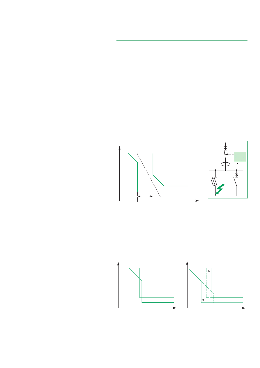
2.2.2. Discrimination between upstream GFP
Devices and downstream SCPDs
Discrimination Rules between GFP Devices and downstream fuses
Because of threshold setting values of GFP devices (a few hundred amps),
protection using GFP devices can interfer with protection using fuse devices
installed downstream in case of an Earth fault.
If downstream switchgear is not fitted out with a Ground Fault Protection device, it is
necessary to verify that the upstream GFP device setting takes the downstream
fuse blowing curve into account.
A study concerning operating curves shows that total discrimination is ensured with:
■
a ratio in the realm of 10 to 15 between the upstream GFP setting threshold and
the rating of downstream fuses
■
an intentional delay of the upstream GFP device that is greater than the breaking
time of the downstream device.
A function of the I²t = constant type on the GFP device setting allows the
discrimination ratio to be slightly improved.
The ratio can be greatly reduced by using a circuit-breaker thanks to the possibility
of setting the magnetic threshold or the short delay of the downstream circuit-
breaker.
I
T
∆
I
30 %
step 1
step 2
I up-
stream
I down-
stream
down-
stream
short
delay
upstream
GFP 1
down-
stream
fuse 2
up-
stream
GFP 1
2
E51135
E51136
T
I
discrimination using settings
upstream
GFP
down-
stream
short
delay
T
I
no discrimination
downstream
short delay
upstream
GFP
Diagram 11 - coordination between upstream GFP device and downstream devices
Diagram 12b
Discrimination Rules between GFP devices and circuit-breakers
■
the above condition is equivelant to a GFP device setting at 1.5 times that of
magnetic protection or time delay of the downstream circuit-breaker
■
if this condition is not verified and so that it may be executed:
❏
lower the magnetic setting threshold while being careful of nuisance tripping on
the downstream outgoer dealt with (especially on the motor feeder)
❏
raise the GFP device threshold while being careful of keeping the installation’s
protection against stray currents because this solution allows the flow of stronger
currents.
Diagram 12a
E51137
E51138
14
relay 2
800 A
point A
point C
point B
relay 3
300 A
circuit-breaker D1
circuit-breaker D3
circuit-breaker D2
relay 1
1200 A
D2
D1
logic
relay
logic
relay
logic waiting
order
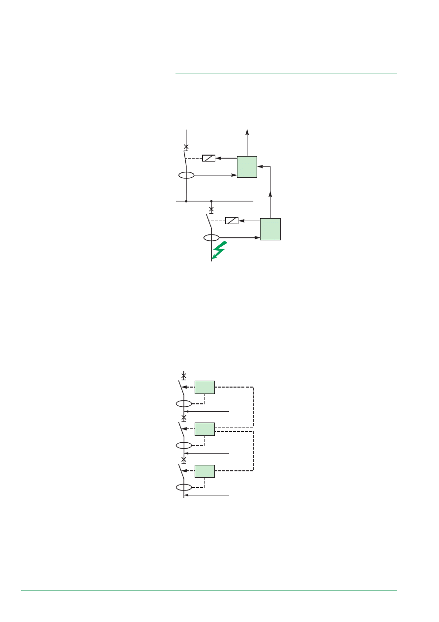
2.2.3. ZSI Logical Discrimination
ZSI = “ Zone Selective Interlocking”
Recommended and greatly used in the USA, it is installed using a pilot wire that
links each of the downstream GFP device functions to the upstream GFP device
function.
E51141
Example 2:
■
an insulation fault occurs at point A and causes a fault current of 1500 A
■
relay no. 1 (threshold at 1200 A) immediately gives the tripping order to circuit-
breaker (A) that has not received a signal from the downstream relays
■
instantaneous tripping of D1 allows stresses on busbars to be greatly
reduced.
Diagram 13a - ZSI discrimination
E51134
Upon fault, the relay located
the nearest to the Earth fault
(for ex. R1) sees the fault,
sends a signal to the
upstream relay (R2) to
indicate to it that it has seen
the fault and that it will
immediately eliminate it. R2
receives this message, sees
the fault but waits for the
signal from R1 and also
sends a signal to R3, etc.
The R2 relay only trips after
a time delay (some ten ms) if
the fault is not eliminated by
R1. (See examples 1 and 2).
This technique allows:
■
discrimination on 3 or more levels to be easily carried out
■
great stress on the installation, which are linked to time-delayed tripping of
protection devices, to be eliminated upon fault that is directly on the upstream
busbars. All protection devices are thus instantaneous.
A pilot wire between all the protection devices dealt with is necessary for this
technique.
Example 1:
■
D1 to D3 circuit-breakers are fitted out with a CU that allows the implementation
of logic discrimination:
❏
an insulation fault occurs at point C and causes a fault current of 1500 A.
■
relay no. 3 (threshold at 300 A) immediately gives
the tripping order to the circuit-breaker (D3) of the
outgoer dealt with:
❏
relay no. 3 also sends a signal to relay no. 2,
which also detected the fault (threshold at 800 A),
and temporarily cancels the tripping order to circuit-
breaker D2 for a few hundred milliseconds, the fault
elimination time needed by circuit-breaker D3
❏
relay no. 2 in turn sends a signal to relay no. 1
❏
relay no. 2 gives the order to open circuit-breaker
D2 after a few hundred milliseconds only if the fault
continues, i.e. if circuit-breaker D3 did not open
❏
id, relay no. 1 gives the order to open circuit-
breaker D1 a few hundred milliseconds after the
fault occured only if circuit-breakers D2 and D3 did
not open.
Diagram 13b - ZSI application
15
In short
Discrimination rules between GFP
devices and circuit-breakers implies
a GFP device to be set at 1.5 times
that of magnetic protection or short
delay of the downstream circuit-
breaker.
2.3. Implementing GFP Coordination
2.3.1. Application Examples
2.3.1.1. Discrimination between GFP devices
Example 1:
■
circuit-breaker D1 is fitted out with a GFP device of the SGR type set at 1200 A
index II (i.e.
D
t = 140 ms)
■
circuit-breaker D2 is fitted out with a GFP2 device of the RS type set at 400 A
instantaneous
■
an insulation fault occurs in B and causes a fault current of 1500 A:
❏
a study concerning tripping curves shows that the 2 relays “see” the fault current.
But only GFP2 makes its device trip instantaneously
❏
discrimination is ensured if the total fault elimination time
d
t2 by D2 is less than
the time delay Dt of D1.
D2
D1
RS
400 A
Inst
SGR
1200 A
100 ms
point B
point A
I
T
GFP2
1200 A
400 A
1500 A
δ
t
2
Inst
GFP1
step 2
D2 tripping
curve
∆
t
I = fault
R1
D2
D1
Id fault
point B
Diagram 14b
E51142
Diagram 12b
E51139
Diagram 14a - tripping curves
E51140
Example 2:
■
an insulation fault occurs in A and causes a fault current of 2000 A:
❏
circuit-breaker D1 eliminates it after a time delay
D
t
❏
the installation undergoes heat stress from the fault during time delay
D
t and the
fault elimination time
d
t1.
2.3.1.2. Discrimination between upstream GFP devices and
downstream SCPDs
Example 1:
■
the upstream circuit-breaker D1 is fitted out with a GFP device that has a
threshold set at 1000 A ±15 % and a time delay at 400ms:
❏
circuit-breaker D2 has a rating of 100 A that protects distribution circuits. The
short delay setting of D2 is at 10 In i.e. 1000 A ±15 %
❏
an insulation fault occurs at point B causing
a fault current Id.
■
a study concerning tripping curves shows
overlapping around the magnetic threshold setting
value (1000 A i.e. 10 In ± 15 %) thus a loss of
discrimination.
By lowering the short delay threshold to 7 In,
discrimination is reached between the 2 protection
devices whatever the insulation fault value may be.
16
2.4. Special Operations of GFP Devices
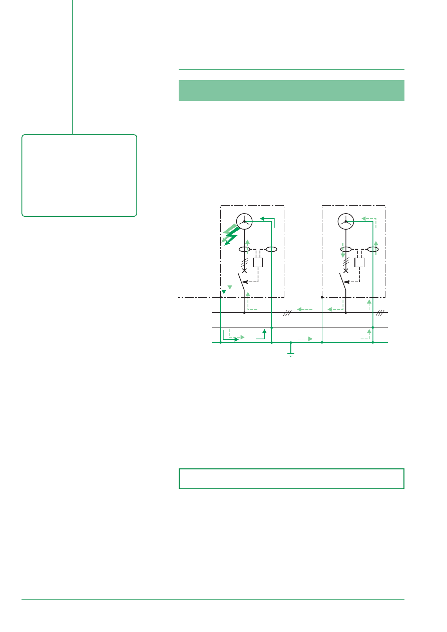
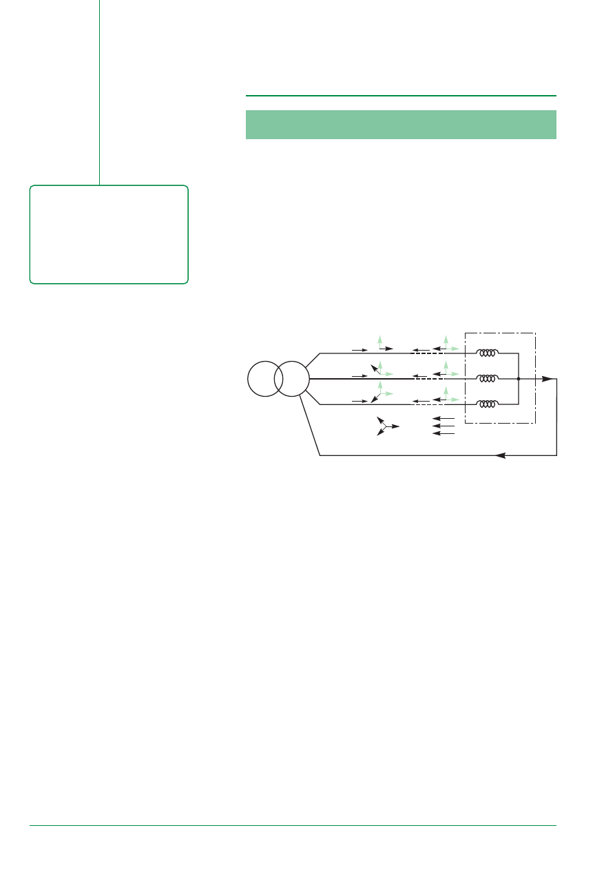
2.4.1. Protecting Generators
An insulation fault inside the metal casing of a generating set may severly damage
the generator of this set. The fault must be quickly detected and eliminated.
Furthermore, if other generators are parallelly connected, they will generate energy
in the fault and may cause overload tripping. Continuity of supply is no longer
ensured.
For this reason, a GFP device built-into the generator’s circuit allows:
■
the fault generator to be quickly disconnected and service to be continued
■
the control circuits of the fault generator to be stopped and thus to diminish the
risk of deterioration.
In short
Protection using GFP devices can
also be used to:
■
protect generators
■
protect loads.
The use of transformers on part of
the installation allows insulation
faults to be confined.
Discrimination with an upstream
GFP device is naturally carried out.
RS
RS
N
PE
non protected
zone
protected
zone
generator no. 1
PE
generator no. 2
PE
Phases
PEN
PE
PEN
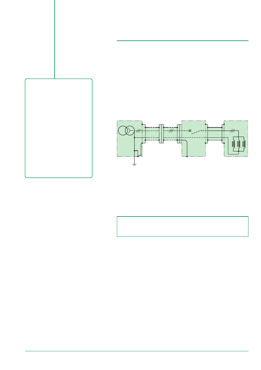
Diagram 15 - “generator protection”
E51145
This GFP device is of the “Residual sensing” type and is to be installed closest to
the protection device as shown in a TN-C system, in each generator set with
earthed exposed conducted parts using a seperate PE:
■
upon fault on generator no. 1:
❏
an earth fault current is established in PE1 Id1 + Id2 due to the output of power
supplies 1 and 2 in the fault
❏
this current is seen by the GFP1 device that gives the instantaneous
disconnection order for generator 1 (opening of circuit-breaker D1)
❏
this current is not seen by the GFP2 device. Because of the TN-C system.
This type of protection is called “restricted differential”.
Installed GFP devices only protect power supplies.
GFP is of the “Residual sensing” RS type.
GFP threshold setting: from 3 to 100 A depending on the GE rating.
17
PE
R
I
d
level 1
level 2
208 V
440 V
Diagram 16 - “transformers and discrimination”
E51143
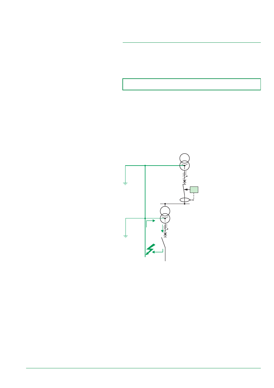
2.4.2. Protecting Loads
A weak insulation fault in motor winding can quickly develop and finish by creating a
short-circuit that can significantly deteriorate even destroy the motor. A GFP device
with a low threshold (a few amps) ensures correct protection by deenergizing the
motor before severe dammage occurs.
2.4.3. Special Applications
It is rather common in the USA to include LV transformers coupled
D
Y in the power
distribution:
■
to lower the voltage
■
mix earthing systems
■
ensure galvanic insulation between the different applications, etc.
This transformer also allows the discrimination problem between the upstream GFP
device and downstream devices to be overcome. Indeed, fault currents (earth fault)
do not flow through this type of coupling.
GFP is of the “Zero Sequence” type.
GFP threshold setting: from 3 to 30 A depending on the load types.
18
T2
T1
S1
S2
P1
P2
R
PE N
3
1
4
2
4
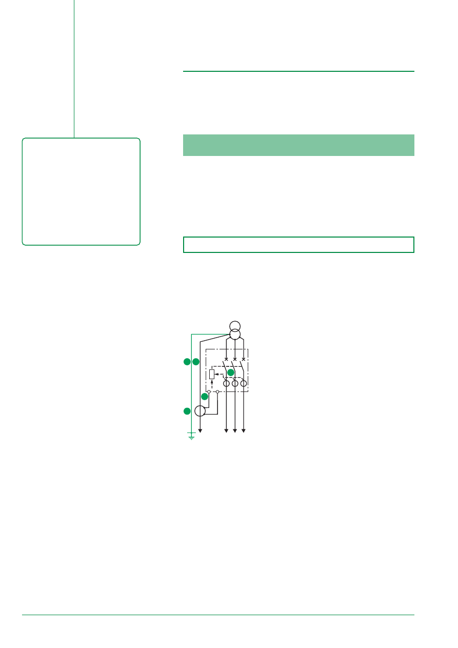
Diagram 17 - “RS system”:
upstream and downstream
power supply
E51146
GFP Implementation
3.1.1. Being sure of the Earthing System
GFP is protection against fire at a high threshold (from a few dozen up to 1200
Amps):
■
in an IT and/or TT type system, this function is not necessary: insulation fault
currents are naturally weak, - less than a few Amps (see § 1.2.1) -
■
in a TN-C system, PE conductors and Neutral are the same: for this reason,
insidious and dangerous insulation fault currents cannot be discriminated from a
normal Neutral current.
The system must be of the TN-S type.
The GFP function operates correctly only:
■
with a true PE conductor, i.e. a protection conductor that only carries fault currents
■
with an Earthing System that favors, upon insulation fault, the flow of a strong
fault current.
3.1. Installation Precautions
Correct implementation of GFP devices on the network consists of:
■
good protection against insulation faults
■
tripping only when it is necessary.
In short
The correct implementation of
GFP devices depends on:
■
the installed ES. The ES must be
of the TN-S type
■
the measurement carried out
❏
not forgetting the Neutral
conductor current
❏
the correct wiring of an external
CT, if used, to the primary as well as
to the secondary,
■
a good coordination
(discrimination) between devices.
3.1.2. Being sure of the GFP Installation
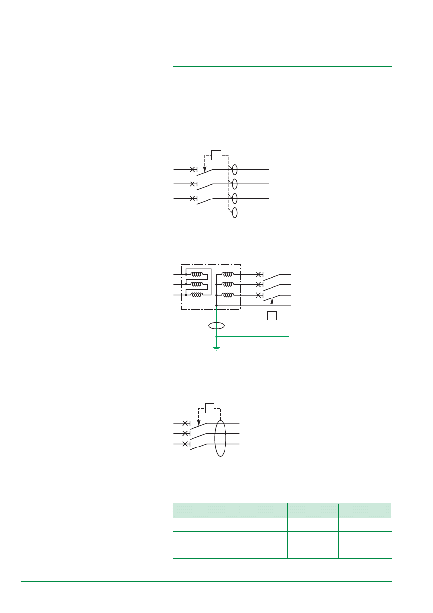
Residual Sensing System
First, it is necessary to verify that:
■
all of the live conductors, including the Neutral
conductor, are controlled by (the) measuring toroid(s)
➲
■
the PE conductor is not in the measuring circuit
➹
■
the Neutral conductor is not a PEN, or does not
become one by system upgrading (case of
multisource)
■
the current measurement in the Neutral (if it is done
by a separate CT) is carried out using the correct
polarity (primary and secondary) so that the protection
device’s electronics correctly calculate the vectorial
sum of Phases and Neutral currents
➤
■
the external CT has the same rating as the CT of
phases
➫
.
Note 1: the use of a 4P circuit-breaker allows problems
➲
to
➫
to be resolved.
Note 2: the location of the measuring CT on the neutral conductor is independent
from the type of switchgear power supply:
■
upstream power supply or
■
downstream power supply.
19
T2
T1
S1
S2
P1
P2
R
PE N
1
4
3
2
4
S1
I
B
S2
P1
P2
1/1000
S1
S2
P1
P2
1/1000
I
A
+ I
B
I
A
A
B
Coupling Measuring CTs
So as to correctly couple 2 measuring CTs or to connect an external CT, it is
necessary:
■
in all cases:
❏
to verify that they all have the same rating
❏
to verify polarity (primary as well as secondary).
■
in the case of coupling at the wiring level of secondaries, it is suggested:
❏
to put them in short-cicuit when they are open (disconnected)
❏
to connect terminals with the same markers together (S1 to S1 and S2 to S2)
❏
Earth the secondary terminal S2 only one of the CTs
❏
to carry out the coupling/decoupling functions on the links of S1 terminals.
Diagram 19a - external CT coupling
E54519
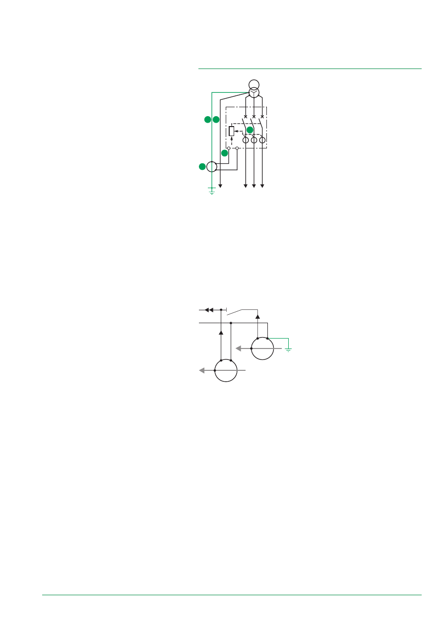
Source Ground Return System
It is necessary to ensure that:
■
measurement is carried out on a PE conductor and
not on a PEN
➹
■
the precautions concerning the CT polarity
described above are taken into account (even if the
measurement is carried out by a single CT, it may
subsequently be coupled to other CTs)
➤
■
the external CT has the same rating as the CT of
phases
➫
.
E54518
Diagram 18 - “SGR system”: upstream and downstream power supply
20
I1H3
+
+
+
IN
+
=
I2H3
I3H3
I1H1
I2H1
I3H1
∑
∑
3
1
IKH1
0
+
3IH3
L1
N
L3
L2
The main problem is ensuring that the TN-S system does not transform into a
TN-C system during operation. This can be dangerous and can disturb the
Neutral conductor in the case of strong current.
3.2.1. Harmonic Currents in the Neutral conductor
Strong natural current flow in the Neutral conductor is due to some non-linear loads
that are more and more frequent in the electrical distribution (1):
■
computer system cut-off power supply (PC, peripherals, etc.)
■
ballast for fluorescent lighting, etc.
These loads generate harmonic pollution that contributes to making a strong earth
fault current flow in the Neutral conductor.
These harmonic currents have the following characteristics:
■
being thirds harmonic or a multiple of 3
■
being permenant (as soon as loads are supplied)
■
having high amplitudes (in any case significantly greater than unbalanced
currents).
Indeed, given their frequency that is three times higher and their current shift in
modules of 2
p
/3, only third harmonic and multiples of three currents are added to
the Neutral instead of being cancelled. The other orders can be ignored.
Facing this problem, several solutions are possible:
■
oversizing the Neutral cable
■
balancing the loads as much as possible
■
connecting a coupled tranformer Y
D
that blocks third order harmonics currents.
The NEC philosophy, which does not foresee protection of the Neutral,
recommends oversizing the Neutral cable by doubling it.
(1) A study conducted in 1990 concerning the power supply of computer type loads shows that:
■
for a great number of sites, the Neutral current is in the realm of 25 % of the medium current per
Phase
■
23 % of the sites have a Neutral current of over 100 % of the current per Phase.
Diagram 20 - third harmonics flow
E51151
3.2. Operating Precautions
In short
During operation, the TN-S system
must be respected.
A “multisource/multigrounding”
installation must be carefully studied
because the upstream system may
be a TN-C and the Neutral conductor
a PEN.
21
PE
PE PEN
N
In
1
In
L
In
2
I1
1
Q1
S1
S2
Q2
earth
loads
loads
earth
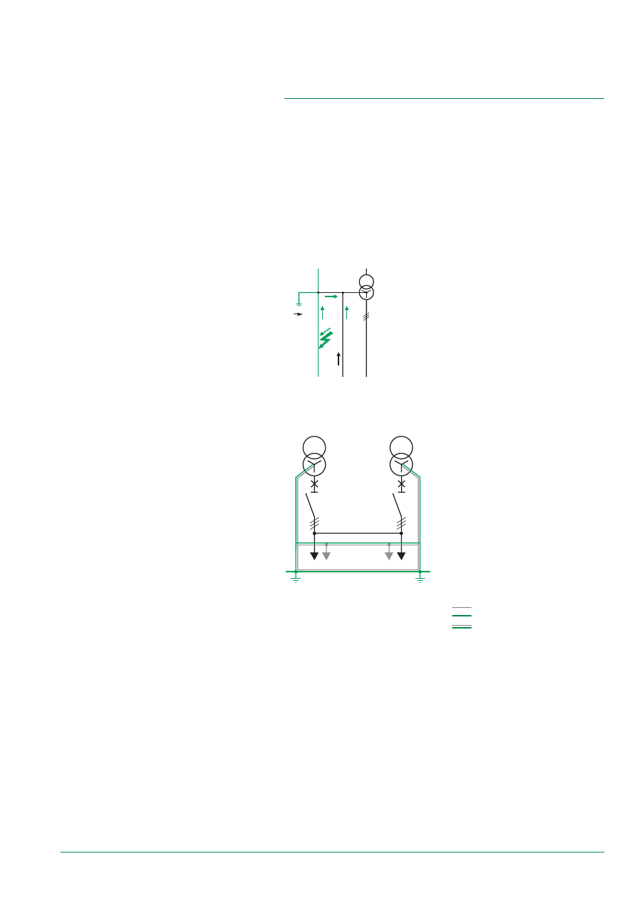
3.2.2. Incidences on GFP Measurement
In a TN-S system, there are no incidences. But caution must be taken so that the
TN-S system does not transform into a TN-C system.
In a TN-C system, the Neutral conductor and the PE are the same. The Neutral
currents (especially harmonics) flow in the PE and in the structures.
The currents in the PE can create disturbances in sensitive switchgear:
■
by radiation of structures
■
by loss of equipotentiality between 2 switchgears.
A TN-S system that transorms into a TN-C system causes the same problems.
Currents measured by GFP devices on the supply end become erroneous:
■
natural Neutral currents can be interpreted as fault currents
■
fault currents that flow through the Neutral conductor can be desensitized or can
cause nuisance tripping of GFP devices.
Examples
case 1: insulation fault on the Neutral conductor
The TN-S system transforms into a TN-C system upon
an insulation fault of the Neutral conductor. This fault
is not dangerous and so the installation does not need
to be deenergised.
On the other hand, current flow that is upstream from
the fault can cause dysfunctioning of GFP device.
The installation therefore needs to be verified to make
sure that this type of fault does not exist.
Diagram 21a - TN-S
transformed into TN-C
E51154
Diagram 21b - multisource / multigrounding
system with a PEN conductor
E54521
case 2: multisource with multigrounding
This is a frequent case especially for
carrying out an installation extension. As
soon as two power supplies are coupled
with several Earthings, the Neutral
conductors that are upstream from
couplings are transformed into PENs.
Note: a single earthing of the 2 power
supplies reduces the problem (current
flow of the Neutral in structures) but:
■
Neutral conductors upstream from
couplings are PENs
■
this system is not very easy to
correctly construct.
Note: the following code will be used to
study the diagrams:
Neutral
P E
P E N
22
Q1
S1
U1
PE
N
PEN
earth
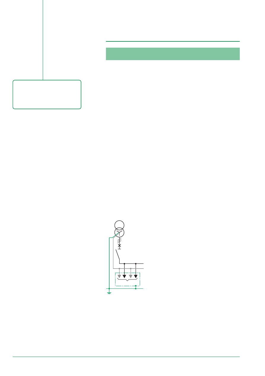
3.3.1. Methodology
The implementation mentioned in paragraph 3.1 consists in verifying 6 criteria.
■
measurement
a 0: the GFP device is physically correctly installed: the measuring CT is correctly
positioned.
The next step consists in verifying on the single-line.
■
TN-S system, i.e.
❐
operating without faults:
a 1: GFP devices do not undergo nuisance tripping with or without unbalanced
and/or harmonic loads
a 2: surrounding sensitive switchgear is not disturbed.
❐
operating with faults:
b 1: the GFP device on the fault outgoer measures the “true” fault value
b 2: GFP devices not dealt with do not undergo nuisance tripping.
■
availability
b 3: discrimination with upstream and downstream protection devices is ensured
upon an insulation fault.
3.3. Applications
Diagram 22 - single-source
E54525
3.3.2. Application: Implementation in a Single-source
TN-S system
It does not present any problems if the above methodology is respected.
■
measurement
a 0 criterion
It is necessary to verify that:
❐
in a “Residual Sensing” system, all of the live cables are monitored and that the
toroid on the Neutral conductor is correctly positioned (primary current direction,
cabling of the secondary)
❐
in a “Source Ground Return” system, the measurement toroid is correctly installed
on the PE (and not on a PEN or Neutral conductor).
■
TN-S system
In short
Implementation of a system with a
single power supply does not
present any particular problems
because a fault or Neutral current
can not be deviated.
a 1 and a 2 criteria
❐
current flowing through the Neutral can only return to
the power supply on one path, if harmonic currents are
or are not in the Neutral. The vectorial sum of currents
(3 Ph + N) is nul.
Criterion a 1 is verified.
❐
the Neutral current cannot return in the PE because
there is only one connection of the Neutral from the
transformer to the PE. Radiation of structures in not
possible.
Criterion a 2 is verified.
b 1 and b 2 criteria
Upon fault, the current cannot return via the Neutral
and returns entirely into the power supply via the PE.
Due to this:
❐
GFP devices located on the feeder supply system
read the true fault current
❐
the others that cannot see it remain inactive.
Criteria b 1 and b 2 are verified.
b 3 criterion
■
availability
❐
discrimination must be ensured according to the
rules in paragraph 2.2.
Criterion b 3 is then verified.
23
Q1
Q3
Q2
R2
R1
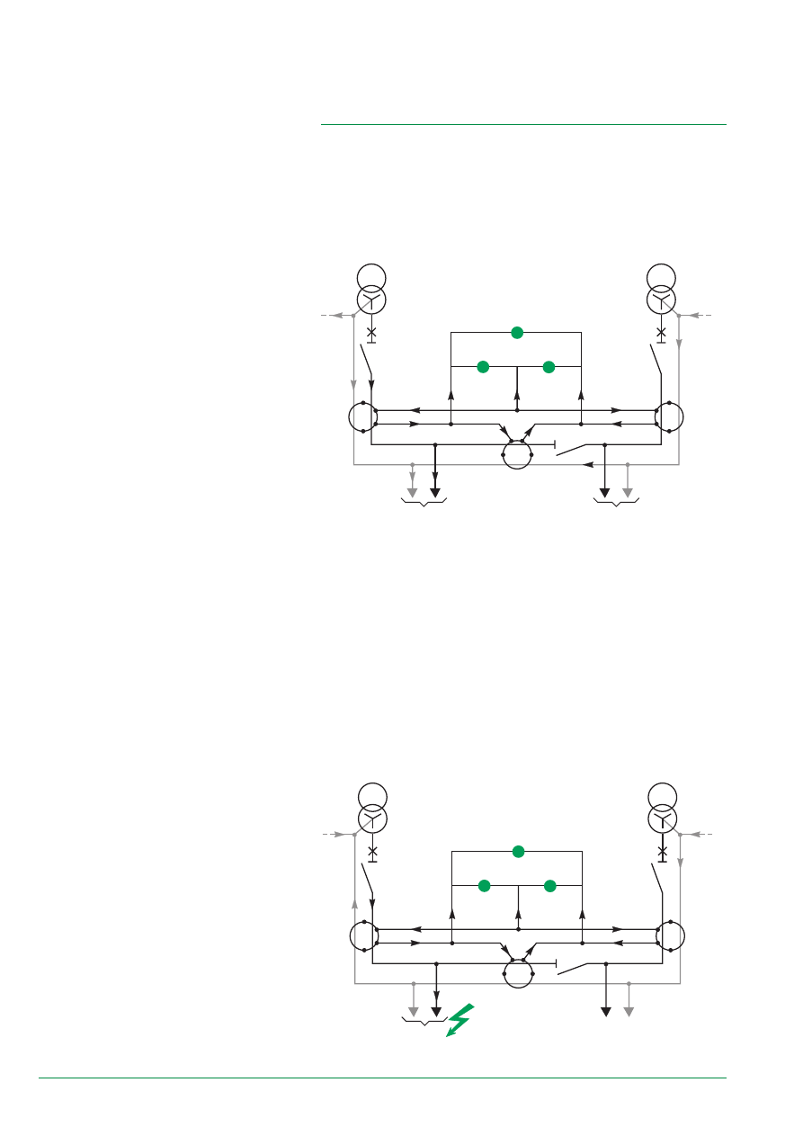
3.3.3. Application: Implementation in a Multisource
TN-S system
The multisource case is more complex.
A multiple number of network configurations is possible depending on:
■
the system (parallel power sources, Normal / Replacement power source, etc.)
■
power source management
■
the number of Neutral Earthings on the installation: the NEC generally
recommends a single Earthing, but tolerates this type of system in certain cases
(§ 250-21 (b))
■
the solution decided upon to carry out the Earthing.
Each of these configurations requires a special case study.
The applications presented in this paragraph are of the multisource type with
2 power sources.
The different schematic diagrams are condensed in this table.
Switchgear Position
Operation
Q1
Q2
Q3
Normal N
C
C
O
Replacement R1
O
C
C
Replacement R2
C
O
C
C: Closed
O: Open
The 6 criteria (a 0, a 1, a 2, b 1, b 2 and b 3) to be applied to each system are
defined in paragraph 3-2-1.
To study all case figures and taking into account the symmetry between GFP1 and
GFP2 devices, 12 criteria must be verified (6 criteria x 2 systems).
In short
As soon as the network has at
least 2 power supplies, the
protection system decided upon
must take into account problems
linked to:
■
third order harmonics and
multiples of 3
■
the non-breaking of the Neutral
■
possible current deviations.
Consequently, the study of a
“multisource” diagram must clearly
show the possible return paths:
■
of the Neutral currents
■
of the insulation fault currents
i.e. clearly distinguish the PE and
the PEN parts of the diagram.
E51158
Diagram 24 - coupling
24
Q2
Q1
Q3
S1
S2
PEN2
PEN1
PE
N2
N1
earth
U1 loads
U2 load
MSB
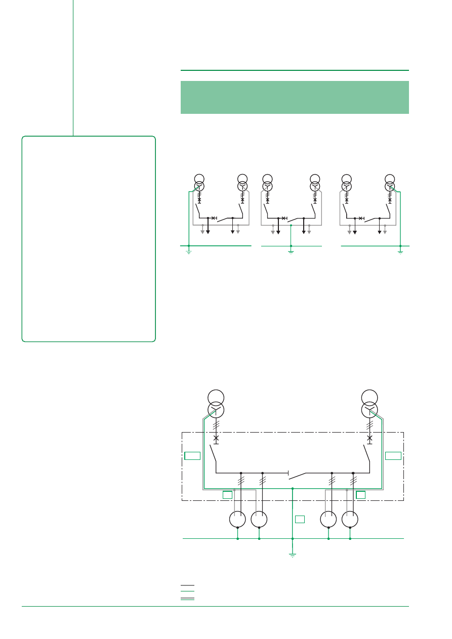
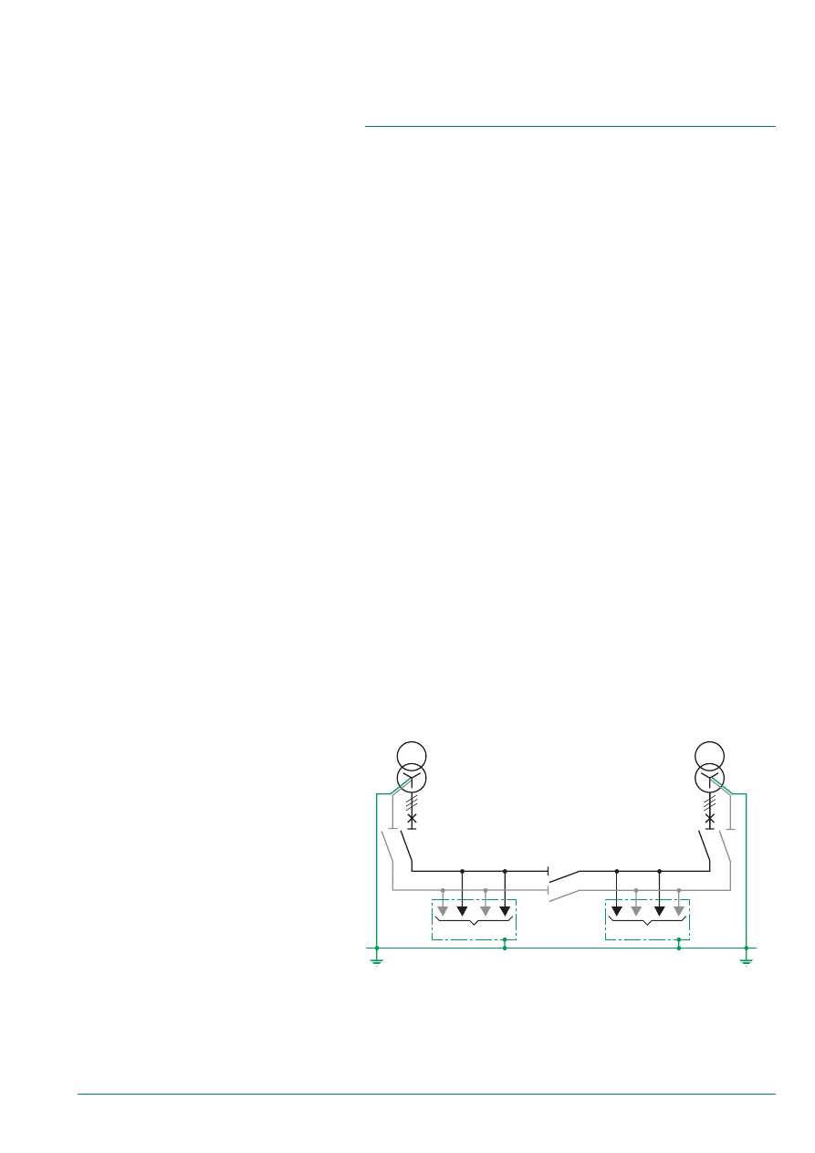
The Multisource / one Grounding
diagram is characterised by a PEN on
the incoming link(s):
■
the diagram normally used is diagram
2 (Grounding is symmetrical and
performed at coupling level)
■
diagrams 1 and 3 are only used in
source coupling.
Characteristics of diagram 2
Ground Fault Protection may be:
■
of the SGR type
■
of the RS type if uncoupling of the load
Neutral is performed properly
■
the incoming circuit-breakers are of the
three-pole type.
Fault management does not require
Ground Fault Protection on the coupler.
Characteristics of diagrams 1 and 3
These diagrams are not symmetrical.
They are advantageous only when used
in source coupling with a GE as a
Replacement source.
E54528
Diagram 26a
These systems are not easily constructed nor maintained in the case of extension:
second earthings should be avoided. Only one return path to the source exists:
■
for natural Neutral currents
■
for PE fault currents.
There are 3 types of diagram (figure 25):
PE
U1 load
U2 load
PE
U1 load
U2 load
PE
U1 load
U2 load
E54538
E54539
E55261
Diagram 2 is the only one used in its present state.
Diagrams 1 and 3 are only used in their simplified form:
■
load U2 (diagram 1) or U1 (diagram 3) absent
■
no Q3 coupling
The study of these diagrams is characterised by a PEN on the incoming link(s).
Consequently, the incoming circuit-breakers Q1 and Q2 must be of the three-pole
type.
4.1.1. Diagram 2
Once Earthing of the Neutral has been carried out using a distribution Neutral
Conductor, the Neutral on supply end protection devices is thus considered to be a
PEN. However, the Earthing link is a PE.
Diagram 1
Diagram 2
Diagram 3
Diagram 25
Study of Multisource Systems
4.1. A Multisource System with a Single
Earthing
In short
Reminder of the coding system used:
Neutral
P E
P E N
25
PEN2
PEN1
PE
N2
N1
Q2
Q1
Q3
S1
S2
SGR 1
SGR 2
earth
U1 loads
U2 load
MSB
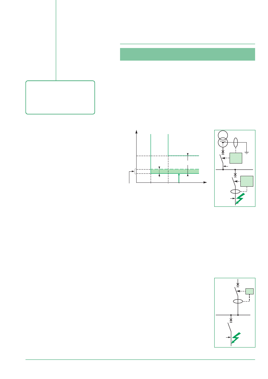
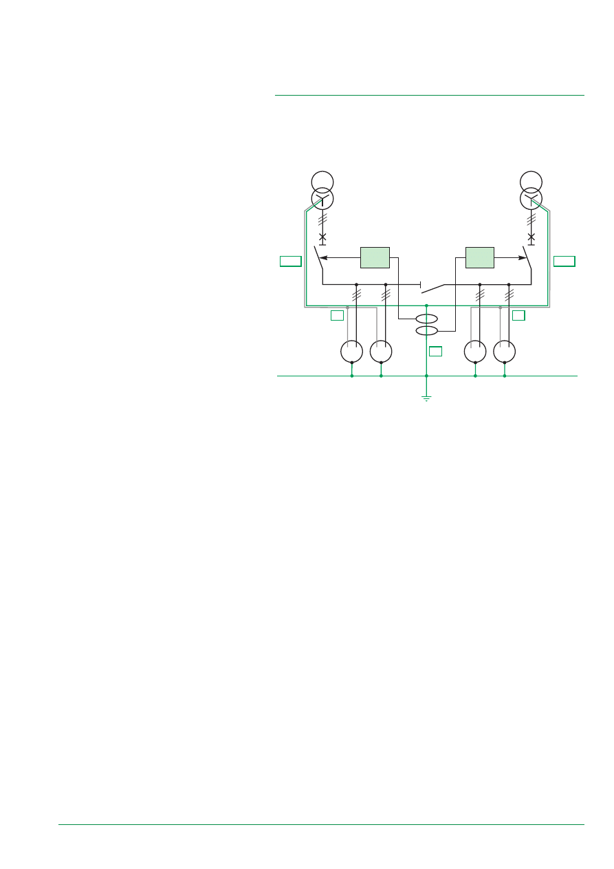
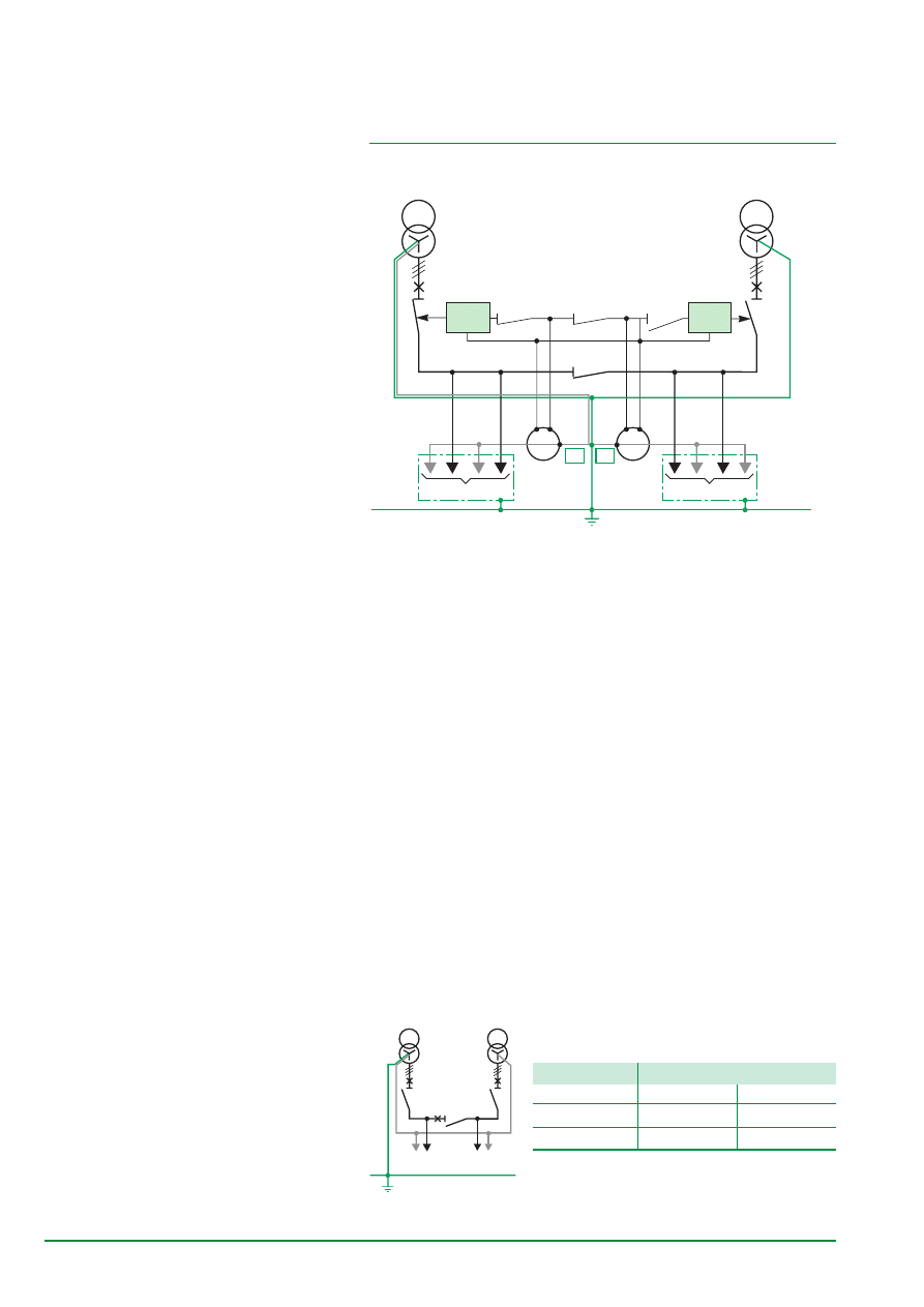
4.1.1.1. Study 1 / diagram 2
The supply end Earth protection device can be implemented using GFP devices of
the Source Ground Return type of which the measuring CTs are installed on this link
(see diagram 26b).
E54529
In normal N operation:
■
a 0 is verified because it deals with a PE
■
a 1, a 2 are verified as well (currents in the Neutral conductor cannot flow in the
PE and the Earth circuits)
■
b 1 is verified
■
b 2 is not verified because it deals with a PE common to 2 parts of the installation
■
b 3 can be verified without any problems.
Implemented GFP devices ensure installation safety because maximum leakage
current for both installations is always limited to 1200 A.
But supply is interrupted because an insulation fault leads to deenergisation of the
entire installation.
For example, a fault on U2 leads to the deenergisation of U1 and U2.
In R1 or R2 replacement operation:
All operation criteria are verified.
To completely resolve the problem linked to b 2 criterion, one can:
■
implement a CT coupling system (Study 2)
■
upgrade the installation system (Study 3).
Diagram 26b - “Source Ground Return” type system
26
Q1
S1
S2
Q2
Q3
U1
U2
q3
q1
q2
SGR 1
SGR 2
S2
S1
P2
P1
S1
S2
P1
P2
A2
A1
earth
Q1
S1
S2
Q2
Q3
U1
U2
q3
q1
q2
SGR 1
SGR 2
S2
S1
P2
P1
S1
S2
P1
P2
PEN2
PEN1
PE
A2
A1
earth
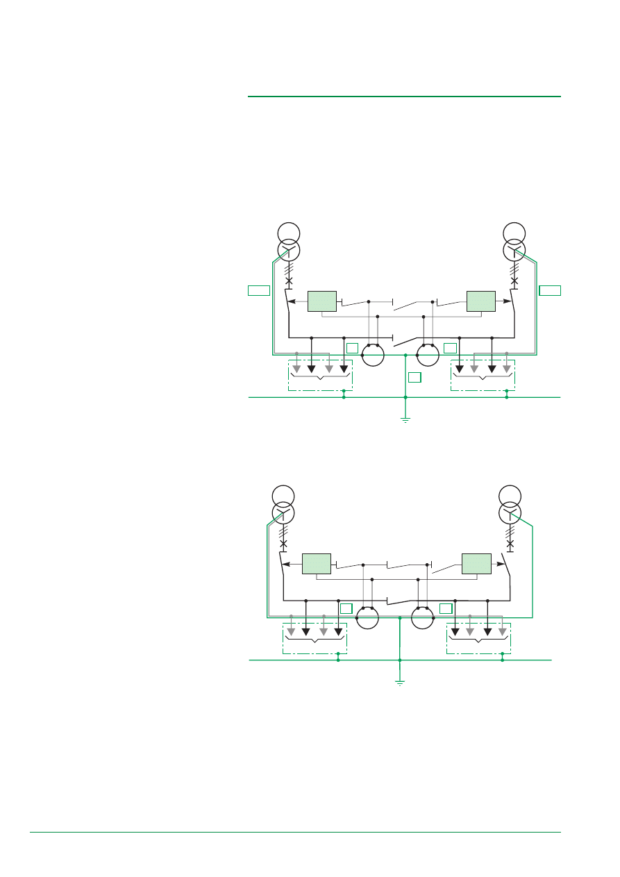
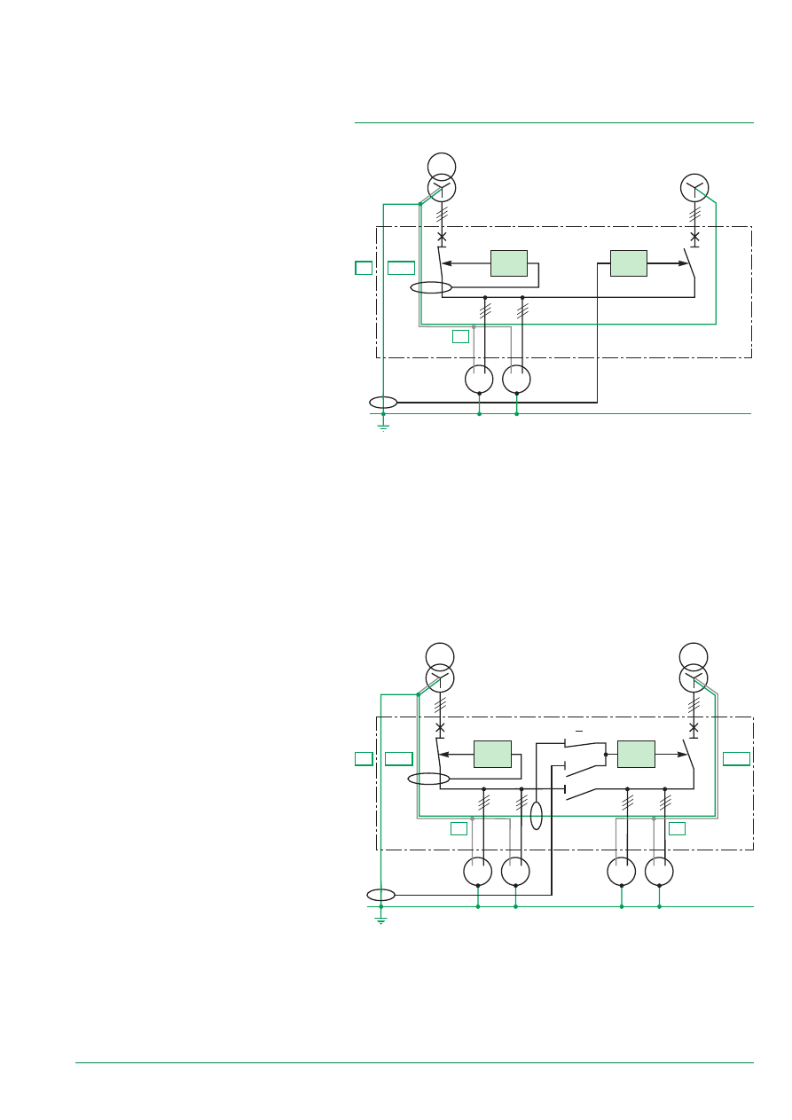
Since link A1 is a PEN for loads U1 and U2 and link A2 is a Neutral for load U2, the
Neutral current measurement can be eliminated in this conductor by coupling the
CTs (see figure 27b).
Fault currents are only measured by the Q1 measurement CT: no discrimination is
possible between U1 and U2.
For this reason, all operation criteria are verified.
Note: measuring CTs must be correctly polorised and have the same rating.
In R2 replacement operation: same principle.
Diagram 27b
E54532
4.1.1.2. Study 2 / diagram 2
Seeing that A1 (or A2) is:
■
a PE in normal N operation
■
a PEN in R1 (or R2) operation
■
a Neutre in R2 (or R1) operation,
measuring CTs on the supply end GFP devices (of the SGR type) can be installed
on these links.
In normal N operation (see diagram 27a)
E54531
Diagram 27a
Operation criteria are verified because A1 (or A2) is a PE.
In R1 replacement operation (see diagram 27b)
27
S1
S2
P1
S2
S1
P1
Q1
S1
S2
Q2
Q3
U1
U2
q3
q1
q2
RS 1
RS 2
PEN
PE
N2
N1
PEN2
PEN1
earth
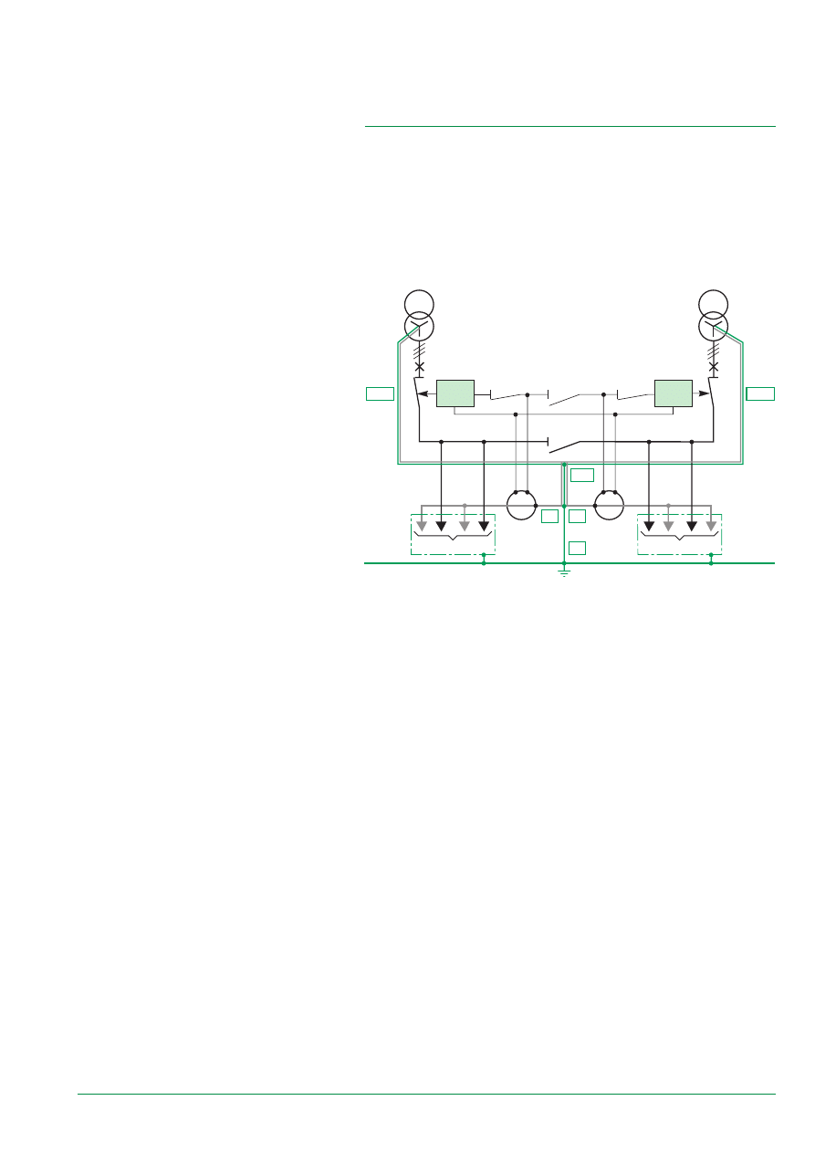
a1 and a2 criteria
The current that flows through the N1 (or N2) Neutral has only one path to return to
the power source. The GFP1 (or GFP2) device calculates the vectorial sum of all
Phases and Neutral currents. a1 and a2 criteria are verified.
b1 and b2 criteria
Upon fault on U1 (or U2), the current cannot return via the N1 (or N2) Neutral. It
returns entirely to the power source via the PE and the PEN1 (or PEN2). For this
reason, the GFP1 (or GFP2) device located on the feeder supply system reads the
true fault current and the GFP2 (or GFP1) device does not see any fault current and
remains inactive.
b3 criterion
Discrimination must be ensured according to the conditions defined in
paragraph 2-2. Therefore, all criteria is verified.
E54533
Diagram 28a
4.1.1.3. Study 3 / diagram 3
In this configuration, used in Australia, the Neutral on supply end devices is
“remanufactured” downstream from the PE. It is however necessary to ensure that
no other upstream Neutrals and/or downstream PEs are connected. This would
falsify measurements.
Protection is ensured using GFP devices of the Residual type that have the Neutral
CT located on this link (of course, polarity must be respected).
In N normal operation (see diagram 28a)
28
S2
S1
P1
S2
S1
P1
Q1
S1
S2
Q2
Q3
U1
U2
q3
q1
q2
RS 1
RS 2
N2
N1
earth
E54534
Diagram 28b
The N1 (or N2) functions are not affected by this operation and so as to manage
protection of the 2 uses (U1 + U2), the sum of Neutral currents (N1+N2) must be
calculated.
CT coupling carried out in diagram 28b allows for these two criteria to be verified.
In R2 replacement operation: same principle.
4.1.1.4. Comments
The diagram with symmetrical Grounding is used in Anglo-Saxon countries. It calls
for strict compliance with the layout of the PE, Neutral and PEN in the main LV
switchboard.
Additional characteristics
n
management of fault currents without measuring CTs on the coupler
n
complete testing of the GFP function possible in the factory: external CTs are
located in the main LV switchboard
n
protection only provided on the part of the installation downstream of the
measuring CTs: a problem if the sources are at a distance.
4.1.2. Diagrams 1 and 3
Diagrams 1 and 3 (see figure 25) are identical.
Note: circuit-breakers Q1 and Q2 must be three-pole.
4.1.2.1. Study of the simplified diagram 1
The operating chart only has 2 states (Normal N or Replacement R2). The diagram
and the chart below (see figure 29) represent this type of application: source 2 is
often produced by GE.
In R1 (or R2) replacement operation (see diagram 28b)
PE
U1 load
U2 load
Diagram 29
E54538
n
without load U2
n
without coupler Q3.
Switchgear position
Operation
Q1
Q2
Normal N
C
O
Replacement R2
O
C
C: Closed
O: Open
29
In Normal N operation
For Q1, the diagram is the same as that of a Single source diagram.
For Q2, GFP2 is of the SGR type with the measurement taken on PE2 (see fig. 30b).
In Normal R1 operation
The diagram is similar to a Single source diagram.
In Normal R2 operation
PE2 becomes a PEN. A 2
nd
external CT on the PE (see figure 30b) associated with
relays takes the measurement.
PEN1
N1
Q2
Q1
S1
GE
RS
SGR
PE
earth
U1 loads
MSB
PEN2
PEN1
N2
N1
Q2
Q1
q3
S1
S2
RS
PE
q3
SGR
Q3
earth
U1 loads
U2 load
MSB
In Normal N operation
The diagram is the same as the Single source diagram (PE and Neutral separate).
There is thus no problem in implementing Ground Fault Protection GFP1 of the RS
or SGR type.
In R2 replacement operation
At Q2, the Neutral and the PE are common (PEN). Consequently, use of a Ground
Fault Protection GFP2 of the SGR type with external CT on the PE is the only
(simple) solution to be used.
4.1.2.2. Study of the complete diagram
This diagram offers few advantages and, moreover, requires an external CT to
ensure proper management of the Ground Fault Protections.
Diagram 30a
Diagram 30b
E58633
E58634
30
GFP1
Q1
S1
S2
Q2
GFP2
IN2
IN2
IN1
IN2
IN2
B
A
load
earth
load
earth
Q1
S1
S2
Q2
Q3
U1
U2
PEN
PEN
PEN
PEN
earth
earth
E54527
Diagram 31 - “multisource system with 2 Earthings”
4.2. A Multisource System with Several
Earthings
The Neutral points on the LV transformers of S1 and S2 power sources are directly
Earthed. This Earthing can be common to both or separate. A current in the U1 load
Neutral conductor can flow back directly to S1 or flow through the earthings.
4.2.1. System Study
■
by applying the implementation methodology to Normal operation.
a1 criterion: balanced loads without harmonics in U1 and U2
For U1 loads, the current in the Neutral is weak or non-existant. Currents in paths A
and B are also weak or non-existant. The supply end GFP devices (GFP1 and
GFP2) do not measure any currents. Operation functions correctly. Id, if one looks
at U2 loads.
a2 criterion with
harmonics on U1 loads
Current flowing in the
Neutral is strong and
thus currents in paths A
and B are strong as well.
Supply end GFP devices
(GFP1 and GFP2)
measure a current that,
depending on threshold
levels, can cause
nuisance tripping.
Operation does not
function correctly.
Currents following path B
flow in the structures. a2
criterion is not verified.
Diagram 32a - “a2 criterion”: current flow in structures
E54523
In short
The Multisource diagram with
several earthings is easy to
implement.
However, at Ground Fault Protection
(GFP) level, special relays must be
used if the Neutral conductor is not
broken.
Use of four-pole incoming and
coupling circuit-breakers eliminates
such problems and ensures easy
and effective management of
Ground Fault Protection (GFP).
31
GFP1
Q1
S1
S2
Q2
GFP2
If
If2
If1
If2
load
earth
load
earth
S1
S2
S2
S1
S2
S1
Q1
Q2
Q3
U1
U2
GFP2
P1
P2
S2
S1
P1
P2
P1
P2
GFP1
GFP3
i2
i1
i3
B
A
C
3
1
2
Diagram 32b - “b1 and b2 criteria”
E54524
b3 criterion
A discrimination study is not applicable as long as the encountered dysfunctionings
have not been resolved.
■
in R1 (or R2) operation.
The dysfunctionings encountered during Normal operation subsist.
The implementation of GFP devices on multisource systems, with several Earthings
and with a connected Neutral, require a more precise study to be carried out.
Furthermore, the Neutral current, which flows in the PE via path B, can flow in the
metal parts of switchgear that is connected to the Earth and can lead to
dysfunctioning of sensitive switchgear.
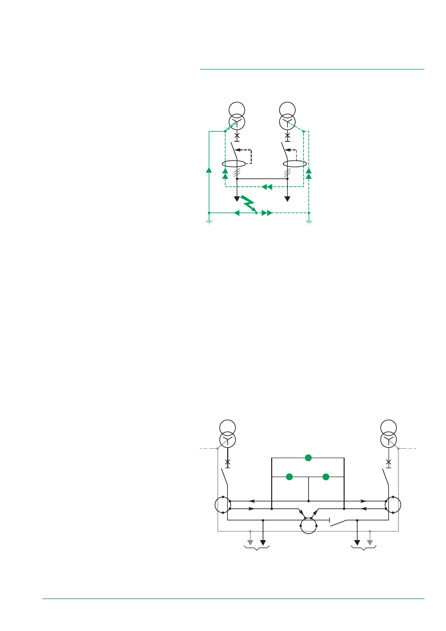
4.2.2. Solutions
4.2.2.1. Modified Differential GFP
Three GFP devices of the Residual Sensing type are installed on protection devices
and coupling (cf. diagram 33a). By using Kirchoff’s laws and thanks to intelligent
coupling of the CTs, the incidence of the natural current in the Neutral (perceived as
a circulating current) can be eliminated and only the fault current calculated.
b1 criterion
For the GFP1 device, the
measured If1 current is
less than the true fault
current. This can lead to
the non-operation of
GFP1 upon dangerous
fault.
Operation does not
function correctly. b1
criterion is not verified.
b2 criterion
For the GFP2 device, an
If2 current is measured
by the supply end GFP
device, even though
there is no fault. This can
lead to nuisance tripping
of the GFP1 device.
Operation does not
function correctly.
In event of a fault on the loads 1, the lf current can flow back via the Neutral
conductor (not broken) if it is shared in lf1 and lf2.
Figure 33a - “logique d’interverrouillage et reconstitution de la mesure”
E51153
32
S2
S2
S2
GFP2
GFP1
GFP3
– iN2 – if2
B
C
If2
If2
If1
If
If
– If
+ If
0
If
3
1
2
IN +
∑
I ph + If
– iN2 + if1
iN2 + if2
→
S2
S2
S2
U1
U2
GFP2
S2
S1
GFP1
GFP3
– iN2
B
A
C
IN2
IN1
IN2
∑
Iph
IN2
0
0
0
IN
+ iN2
∑
Iph
IN
IN2
0
IN2
3
1
2
E58636
■
From the remarks formulated above (see paragraph 4.2.1.), the following can be
deduced:
❏
I
®
= I
®
Nl + I
®
N2
❏
primary current in GFP1: I
®
1 = I
®
N1 +
S
I
®
ph = - I
®
N2
❏
secondary current of GFP1: i1 = - iN2
Likewise, the measurement currents of GFP2 and GFP3:
❏
secondary current of GFP2: i2 = iN2
❏
secondary current of GFP3: i3 = - iN2
■
With respect to secondary measurements, iA, iB and iC allow management of the
following GFPs:
❏
iA = i1 - i3
®
iA =0
❏
iB = i1 - i2
®
iB = 0
❏
iC = i2 + i3
®
iC = 0
■
Conclusion: no (false) detection of faults: criterion a1 is properly verified.
Study 2: Management of fault currents
Diagram 33b - U1 Neutral current
Study 1: Management of Neutral currents
To simplify the reasoning process, this study is conducted on the basis of the
following diagram:
■
Normal operation N
■
load U1 generating Neutral currents (harmonic and/or unbalance), i.e. phase
lU1 =
å
I
®
ph, neutral lU1 = IN
■
no load U2, i.e. phase lU2 = 0, neutral lU2 = 0
■
no faults on U1/U2, i.e.
å
I
®
ph + I
®
N = 0.
E58635
➲
activated.
➹
activated.
➤
gives the fault value.
Diagram 33c - simplified fault on U1: no Neutral current (
S
I
®
ph = 0, IN = 0)
33
Q1
S1
S2
Q2
Q3
U1
U2
earth
earth
Diagram 34
E54537
Same operating principle as for study 1, but:
■
Normal operation N
■
load U1 generating Neutral currents (harmonic and/or unbalance),
i.e. phase lU1 =
å
I
®
ph, neutral lU1 = IN
■
no load U2, i.e. phase lU2 = 0, neutral lU2 = 0
■
faults on U1 ( I
®
f), i.e.
å
I
®
ph + I
®
N + I
®
f = Ø.
■
Using study 1 and the remarks formulated above (see paragraph 4.2.1.),
the following can be deduced:
❏
I
®
f = I
®
f1 + I
®
f2
❏
primary current in GFP1: I
®
1 = I
®
N2 + I
®
- I
®
f2 = - I
®
N2 + I
®
f1
❏
secondary current of GFP1: i1 = - iN2 + if1.
Likewise, the measurement currents of GFP2 and GFP3:
❏
secondary current of GFP2: i2 = iN2 + if2
❏
secondary current of GFP3: i3 = - iN2 - if2.
■
i.e. at iA, iB and iC level: iA = if, iB = - if and ic = Ø.
■
Conclusion: exact detection and measurement of the fault on study 1: no
indication on study 2. Criteria b 1 and b 2 are verified.
Remarks: Both studies show us that it is extremely important to respect the primary
and secondary positioning of the measurement toroids.
Extensively used in the USA, this technique offers many advantages:
■
it only implements standard RS GFPs
■
it can be used for complex systems with more than 2 sources: in this case
coupling must also be standardised
■
it can be used to determine the part of the diagram that is faulty when the
coupling circuit-breaker is closed.
On the other hand, it does not eliminate the Neutral circulating currents in the
structures. It can only be used if the risk of harmonic currents in the neutral is small.
4.2.2.2. Neutral Breaking
In fact, the encountered problem is mainly due to the fact that there are 2 possible
paths for fault current return and/or Neutral current.
In Normal Operation
Coupling using a 4P switchgear allows the Neutral path to be broken. The
multisource system with several Earthings is then equivalent to 2 single-source
systems. This technique perfectly satisfies implementation criteria, including the a 2
criterion, because the TN-S system is completely conserved.
In R1 and R2 Operation
If this system is to be used in all case figures, three 4P devices must be used.
This technique is used to correctly and simply manage Multisource diagrams with
several Earthings, i.e.:
■
GFP1 and GFP2, RS or SGR standards
■
GFP3 (on coupling), RS standard not necessary, but enables management in R1
(or R2) operation of the fault on load U1 or U2.
Moreover, there are no more Neutral currents flowing in the structures.
34
The methodology, especially § 331 p. 22, must be followed:
■
measurement:
❏
physical mounting of CTs and connection of CT secondaries according to the
rules of the trade
❏
do not forget the current measurement in the Neutral conductor.
■
Earthing System:
The system must be of the TN-S type.
■
availability:
Discrimination between upstream GFP devices must be ensured with:
❏
downstream GFP devices
❏
downstream short delay circuit-breakers.
5.1 Implementation
In short
Protection using GFP devices is vital
for reducing the risk of fire on a LV
installation using a TN-S system
when Phases / PE fault impedance is
not controlled.
To avoid dysfunctioning and/or
losses in the continuity of supply,
special attention is required for their
implementation.
The Single-source diagram presents
no problems.
The Multisource diagram must be
carefully studied.
The Multisource diagram with
multiple earthings and four-pole
breaking at coupling and incomer
level, simplifies the study and
eliminates the malfunctions.
5.2 Wiring Diagram Study
Two case figures should be taken into consideration:
■
downstream GFP in sub-distribution (downstream of eventual source couplings):
no system problem.
The GFP device is of the Residual Sensing (RS) type combined with a 3P or 4P
circuit-breaker.
■
upstream GFP at the incomer general protection level and/or at the coupling level,
if it is installed: the system is to be studied in more detail.
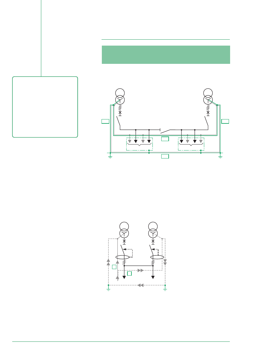
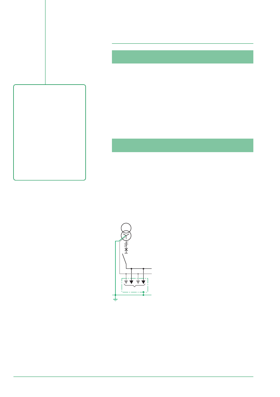
5.2.1. Single-source System
This system does not present any particular problems if the implementation
methodology is respected.
Conclusion
Diagram 22 - single-source system
E54525
Q1
S1
U1
PE
N
PEN
earth
35
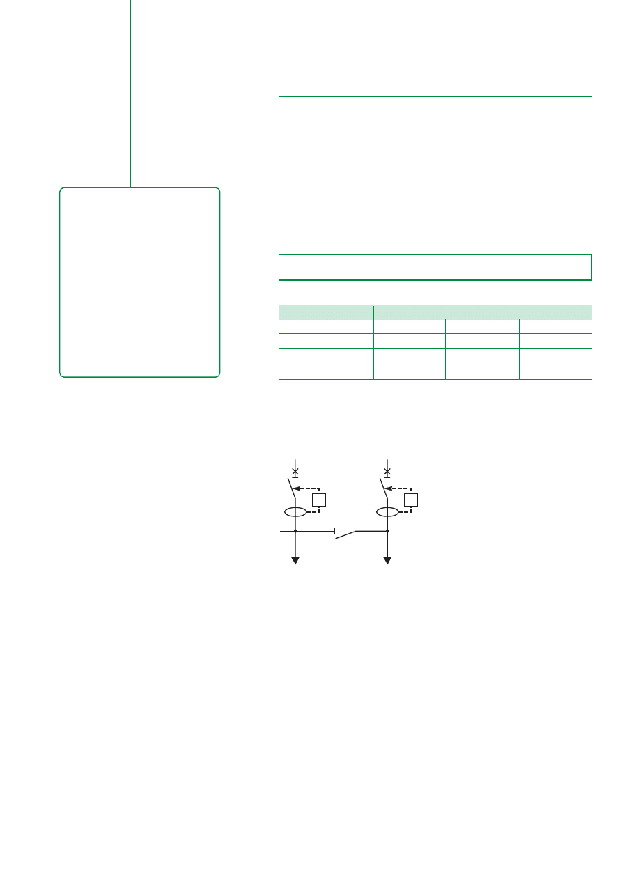
5.2.2.2. Replacement Operation
In replacement operation, the correct paralleling of external CTs allows for insulation
fault management.
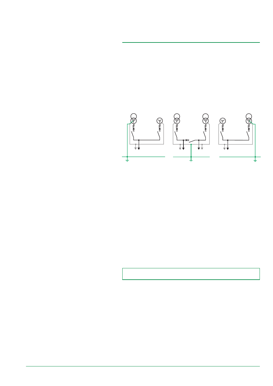
5.2.3. Multisource / Multiground System
This system is frequently used. Circulating current flow can be generated in PE
circuits and insulation fault current management proves to be delicate.
Efficiently managing this type of system is possible but difficult.
4P breaking at the incomer circuit-breaker level and coupling allow for
simple and efficient management of these 2 problems.
This system thus becomes the equivalant of several single-source systems.
System 1
Only useful in source
coupling (no Q3 coupling) =
case of the GE
System 2
Accessible Neutral
Conductors and PE for each
source. The GFP1 (GFP2)
device is:
■
of the RS type with an
exteranl CT on the Neutral
conductor N1 (N2)
■
of the SGR type with an
external CT on the PE
conductor PE1 (PE2)
System 3
Only useful in source
coupling (no Q3 coupling) =
case of the GE
5.2.2. Multisource / Single-ground System
This type of system is not easy to implement: it must be rigorously constructed
especially in the case of extension (adding an additional source). It prevents the
“return” of Neutral current into the PE.
Source and Coupling circuit-breakers must be 3P.
5.2.2.1. Normal Operation
To be operational vis-à-vis GFP devices, this system must have:
■
either, a Neutral conductor for all the users that are supplied by each source:
measurement is of the RS type.
■
or, a PE conductor for all of the users that ar supplied by each source:
measurement is of the SGR type.
PE
GE
U1 load
PE
U1 load
U2 load
PE
GE
U1 load
E58637
E54539
E58638
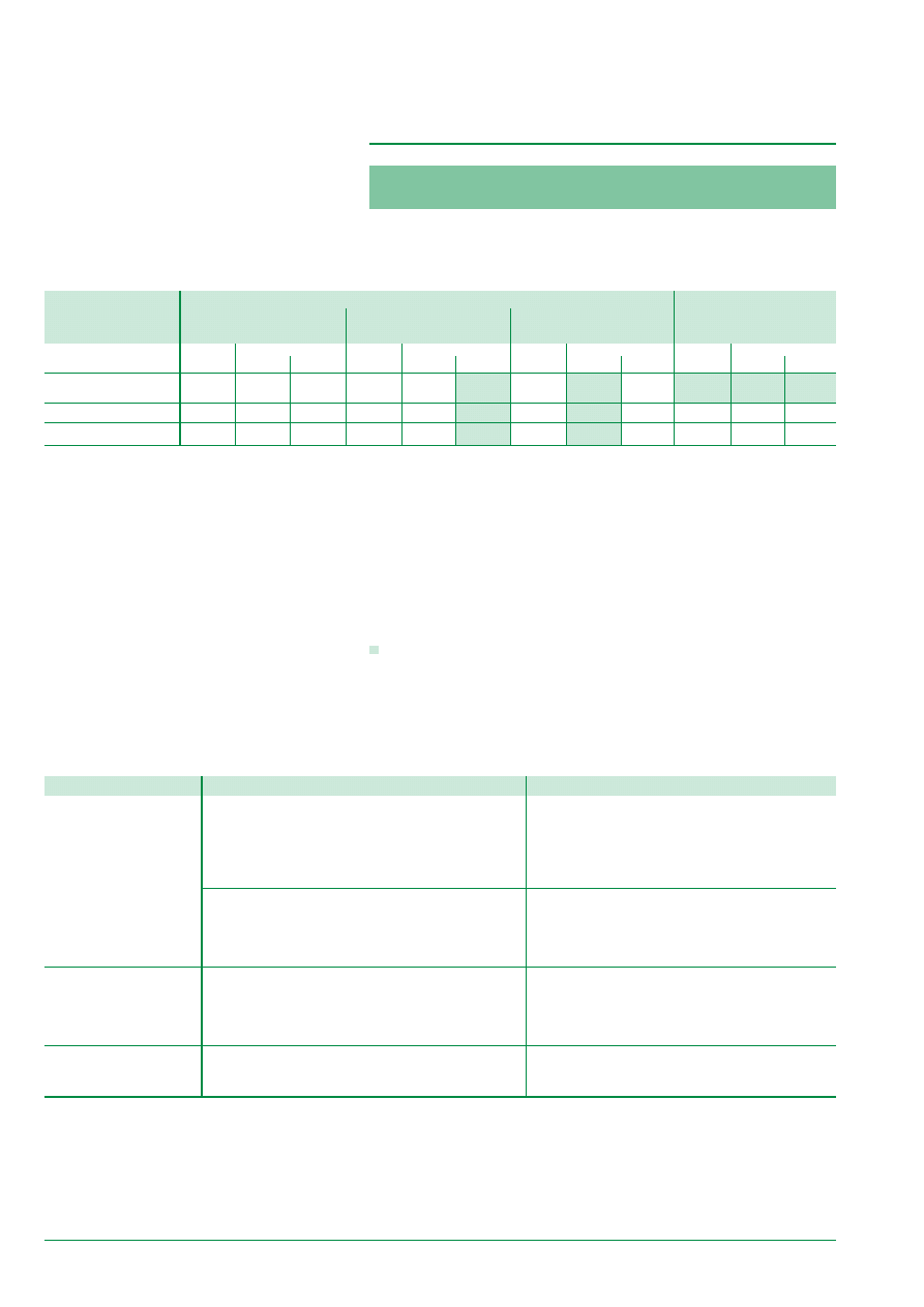
36
5.3.2. Advantages and Disadvantages depending on
the Type of GFP
Different analyses, a comparative of different GFP types.
Advantages
Disadvantages
Residual Sensing
CT of each Phase and Neutral built-into the circuit-
Tolerance in measurements
with 4P circuit-breaker
breaker (standard product)
(only Low Sensitivity > 100 A)
(CT on built in Neutral)
Manufacturer Guarantee
Assembled by the panel builder (can be factory tested)
Safe thanks to its own current supply
Can be installed on incomers or outgoers
with 3P circuit-breaker
Assembled by the panel builder (can be factory tested)
Tolerance in measurements (only LS > 100 A)
(CT on external Neutral )
Can be applied to different systems: a Neutral conductor
Neutral current measurement cannot be forgotten
can be used “separately” from the circuit-breaker
The CT is not built into the circuit-breaker =
Safe thanks to its own current supply
good positioning of the Neutral’s CT (direction)
Can be installed on incomers or outgoers
Source ground return
Can be applied to different systems: a PE conductor
The CT is not built into the circuit-breaker
can be used “separately” from the circuit-breaker
Requires access to the transformer (factory testing not
Safe thanks to its own current supply
possible)
Can be added after installation
Cannot be installed on sub-distributed outgoers
Zero sequence
Can detect weak current values (< 50 A)
Requires an auxiliary source
Uses autonomous relays
Difficult installation on large cross-section conductors
Toroid saturation problem (solutions limited to 300 A)
5.3 Summary Table
5.3.1. Depending on the Installation System
The table below indicates the possible GFP choices depending on the system.
Installation Supply End
Sub-distribution
Type of GFP
Single-source
Multisource /
Multisource /
All Systems
Single-ground
Multiground
GFP
combined CB
GFP
combined CB
GFP
combined CB
GFP
combined CB
3P
4P
3P
4P
3P
4P
3P
4P
Source Ground Return
❏
❏
■
❏
(2)
■
❏
■
(4)
SGR
Residual Sensing RS
❏
❏
■
(1)
❏
(2)
■
■
(3)
■
(4)
■
❏
■
Zero Sequence (5) ZS
❏
❏
❏
❏
■
❏
■
(4)
❏
❏
❏
(1) allows for an extension (2nd source) without any problems.
(2) if a Neutral for each source is available, the RS type can be used if a PE for
each source is available, the SGR type can be used, in all cases, an SGR type can
be used on the general PE (but with discrimination loss between sources).
(3) allows for protection standardisation.
(4) 3P is possible but the system is more complicated and there is Neutral current
flow in the PE.
(5) used for weak current values (200 A).
Key:
■
required or highly recommended,
❐
possible,
forbidden or strongly disrecommended.
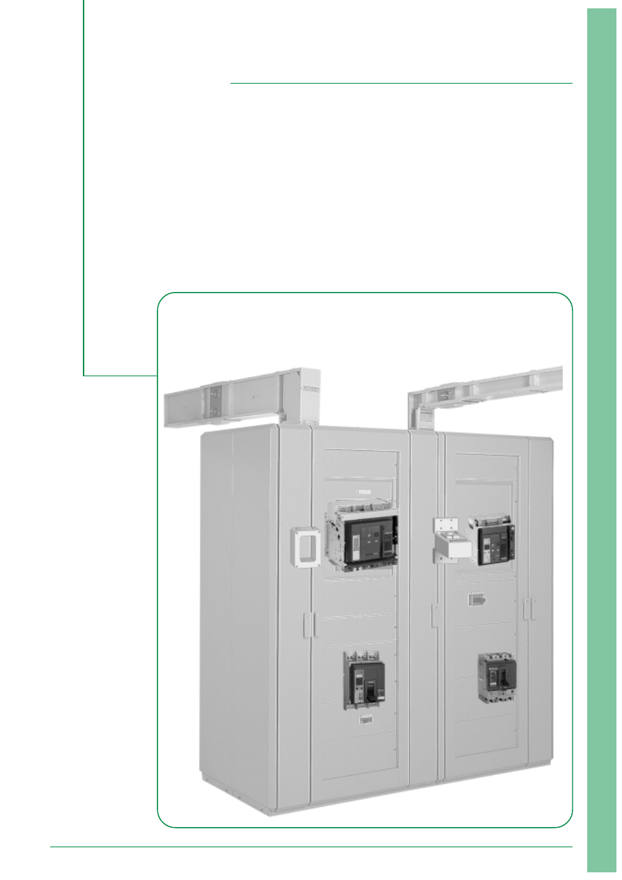
37
Applications
Ground Fault Protection with Masterpact NT/NW
p 38
Ground Fault Protection with Compact NS630b/1600
and NS1600b/3200
p 40
Ground Fault Protection with RH relays
p 44
and toroids of the A, OA and E types
Implementation in the installation
p 46
Study of discrimination between GFP
p 48
Study of ZSI discrimination
p 50
Installation and implementation
of GFP solutions
E55489
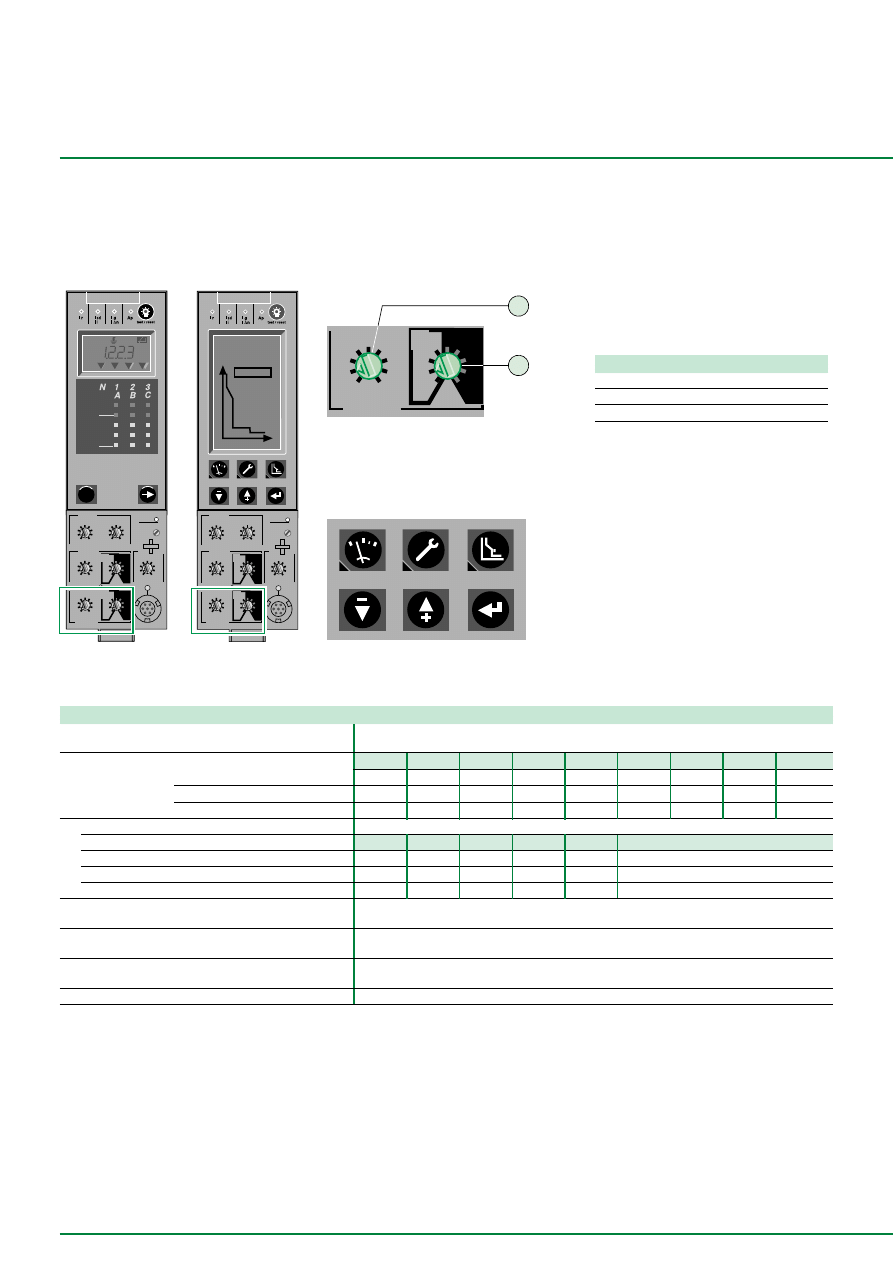
38
ground fault
B
C
D
E
F
G
H
J
Ig
tg
(s)
on
I
2
t
.
2
.
3
.
4
.
4
.
1
.
2
.
3
.
1
0
off
A
1
2
Micrologic 6.0 A
40
100 %
%
menu
.4
.5
.6
.7
.8
.9
.95
.98
1
delay
short time
I i
tsd
(s)
on
I
2
t
.
2
.
3
.
4
.
4
.
1
.
2
.
3
.
1
0
off
instantaneous
long time
alarm
Ir
x In
ground fault
B
C
D
E
F
G
H
J
Ig
tg
(s)
on
I
2
t
.
2
.
3
.
4
.
4
.
1
.
2
.
3
.
1
0
off
A
.5
1
2
4
8
12
16
20
tr
(s)
@ 6 Ir
24
setting
x Ir
2
2.5
3
4
5
6
8
10
Isd
1.5
x In
test
2
4
10
3
6 8
12
15
off
kA
s
Ir=
Ii=
tr=
Isd=
Ig=
tsd=
∆
t=
tg=
I
∆
n=
MAX
Micrologic 6.0 P
.4
.5
.6
.7
.8
.9
.95
.98
1
delay
short time
I i
tsd
(s)
on
I
2
t
.
2
.
3
.
4
.
4
.
1
.
2
.
3
.
1
0
off
instantaneous
long time
alarm
Ir
x In
ground fault
B
C
D
E
F
G
H
J
Ig
tg
(s)
on
I
2
t
.
2
.
3
.
4
.
4
.
1
.
2
.
3
.
1
0
off
A
setting
x Ir
2
2.5
3
4
5
6
8
10
Isd
1.5
.5
1
2
4
8
12
16
20
tr
(s)
@ 6 Ir
24
x In
test
2
4
10
3
6 8
12
15
off
I
(A)
Trip
20 kA
0.4s
Off
24s
2000A
Additional technical information
Ground Fault Protection with Masterpact NT/NW
E68125
Micrologic 6.0 A
Micrologic 6.0 P/H
Technical data and Settings
E68126
E68128
Trip units
Micrologic 6.0 A/P/H
Micrologic 6.0 A/P/H
Setting by switch
1 tripping threshold on a Ground fault.
2 time delay on a Ground fault and l
2
t on/off.
Micrologic 6.0 P/H
Setting by keyboard
E68127
3 selection key of parameter lg.
4 parameter setting and memorisation keys
(including lg).
The Micrologic 6.0 A/P/H trip units are
optionally equipped with Ground Fault
Protection. A ZSI terminal block allows
several control units to be linked to obtain
GFP total discrimination without time delay
tripping
Catalog Numbers
Micrologic 6.0A
33073
Micrologic 6.0P
47059
Micrologic 6.0H
47062
Functions
Micrologic 6.0A/P/H
“Ground Fault“ Protection of the “residual“ type
■
or the “source ground return“ type
Threshold setting
A
B
C
D
E
F
G
H
J
by switch
In
≤
400 A
Ig = In x …
0,3
0,3
0,4
0,5
0,6
0,7
0,8
0,9
1
accuracy : ±10 %
400 A < In
≤
1200 A Ig = In x …
0,2
0,3
0,4
0,5
0,6
0,7
0,8
0,9
1
In > 1200 A
Ig = …
500
640
720
800
880
960
1040
1120
1200
Time delay (th)
settings
with I2t ON
0
0,1
0,2
0,3
0,4
with I2t OFF
0,1
0,2
0,3
0,4
maximum overcurrent time without tripping (ms)
20
80
140
230
350
maximum breaking time (ms)
80
140
230
350
500
Indication of fault type (F) including Ground fault
■
by LED on the front panel
Fault indication contact including Ground fault
output by dry contact
■
Logic discrimination (Z)
by opto-electronic contact
■
External supply by AD module (1)
■
(1) This module is necessary to supply the indication (but not necessary to supply the protection).
Note :
■
With micrologic 6.0 P and H, each threshold over may be linked either to a tripping (protection) or to an indication, made by a programmable contact M2C or
optionnal M6C (alarm). The both actions, alarm and protection, are also available.
■
The ZSI cabling , identical for Masterpact NT/NW, Compact NS630b/1600 and Compact NS1600b/3200 is in details page 42
■
The external supply module AD and battery module BAT, identical for Masterpact NT/NW, Compact NS630b/1600 and Compact NS1600b/3200, are in details
page 42.
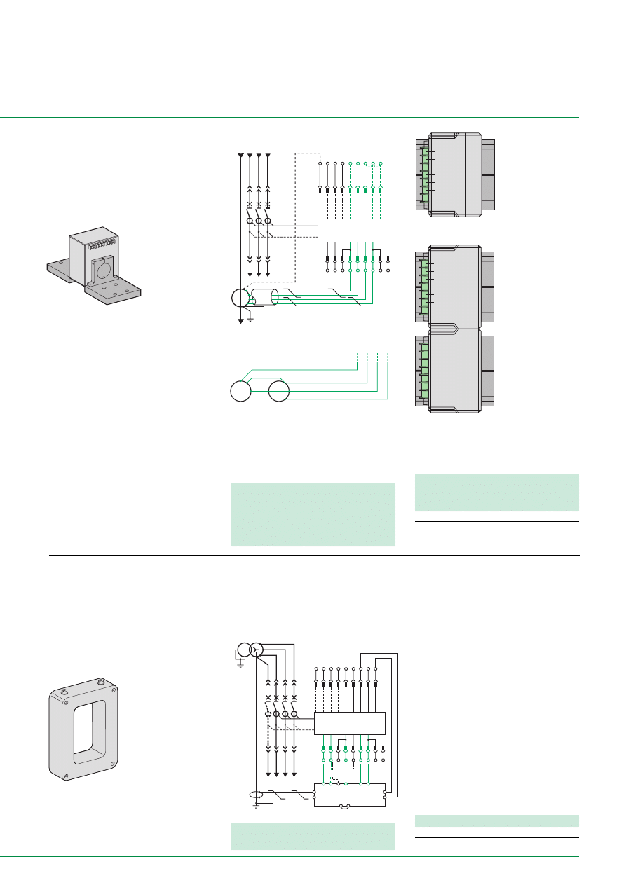
39
SG1
SG2
X1
X2
GND
VN
VC
SG1
SG2
X1
X2
GND
VN
VC
T4
T3
T2
T1
Micrologic 6
Z4
Z3
Z2
Z1
N
L3
L2
L1
Z5
VN
V1
V2
V3
M3
M2
M1
F2+
F1
Ñ
I
U
X2
VN
X1
SG2
SG1
Q
GND
H2
H1
to source
to receivers
External Transformer (CT)
for residual GF Protection
It is used with 3P circuit breakers and is
installed on the neutral conductor to
achieve a GFP protection of Residual type.
E68129
E47697
E68132
External Transformer for
Source Ground Return GFP
protection
It is installed on the from LV transformer
starpoint to the ground link and is
connected to Micrologic 6.0 trip unit by
“MDGF summer” module to achieve the
Ground Fault Protection of SGR type.
If the 2000/6300 current transformer is
used: signals SG1 and SG2 must be wired
in series, signals X1 and X2 must be wired
in parallel.
Masterpact NT and NW08/40
Masterpact NW40b/63
Cabling Précautions:
■
Shielded cable with 2 twisted pairs
■
Shielding connected to GND on one end
only
■
Maximum length 5 meters
■
Cable cross-sectional area to 0.4 to
1.5 mm
2
■
Recommended cable: Belden 9552 or
equivalent.
■
The external CT rating may be compatible
with the circuit breaker normal rating :
NT06 à NT16 : CT 400/1600
NW08 à NW20 : CT 400/2000
NW25 à NW40 : CT 1000/4000
NW40b à NW63 : CT 2000/6300
The signal connection Vn is necessary only
for power measurement (Micrologic P/H)
T4
T3
T2
T1
Micrologic 6
Z4
Z3
Z2
Z1
Z5
VN
V1
V2
V3
M3
M2
M1
F2+
F1
I
U
Q
10 11
7
6
5
12
8
9
1
3
13 14
MDGF module
X1
X2
PE
H1
H2
or
E68130
Cabling Protections:
■
Unshielded cable with 1 twisted pair
■
Shielding connected to GND on one end
only
■
Maximum length 150 meters
■
Cable cross-sectional area to 0.4 to
1.5 mm
2
■
Recommended cable: Belden 9552 or
equivalent.
■
Terminals 5 et 6 are exclusives :
the terminal 5 for Masterpact NW08 à 40
the terminal 6 for Masterpect NW40b à 63
Catalog Numbers
ratings (A)
NT
NW
400/2000
33576
34035
1000/4000
34035
2000/6300
48182
Wathever the Masterpact feeding type, by
open or bottom side, the power connection
and the terminal connection of external CT
are compulsary the same of those phases
CT ones.
Feeding by open side H2 is connected
to source side and H1 to receiver side.
Feeding by bottom side H1 is
connected to source side and H2 to
receiver side.
E68388
E68389
H1 is connected to source side and
H2 to receiver side.
Catalog Numbers
Current Transformer SGR
33579
MDGF module
48891
E68131
H2
H1
H2
H1
X2
SG2
X2
SG2
T4
T3
T2
T1
X1
X1
SG1
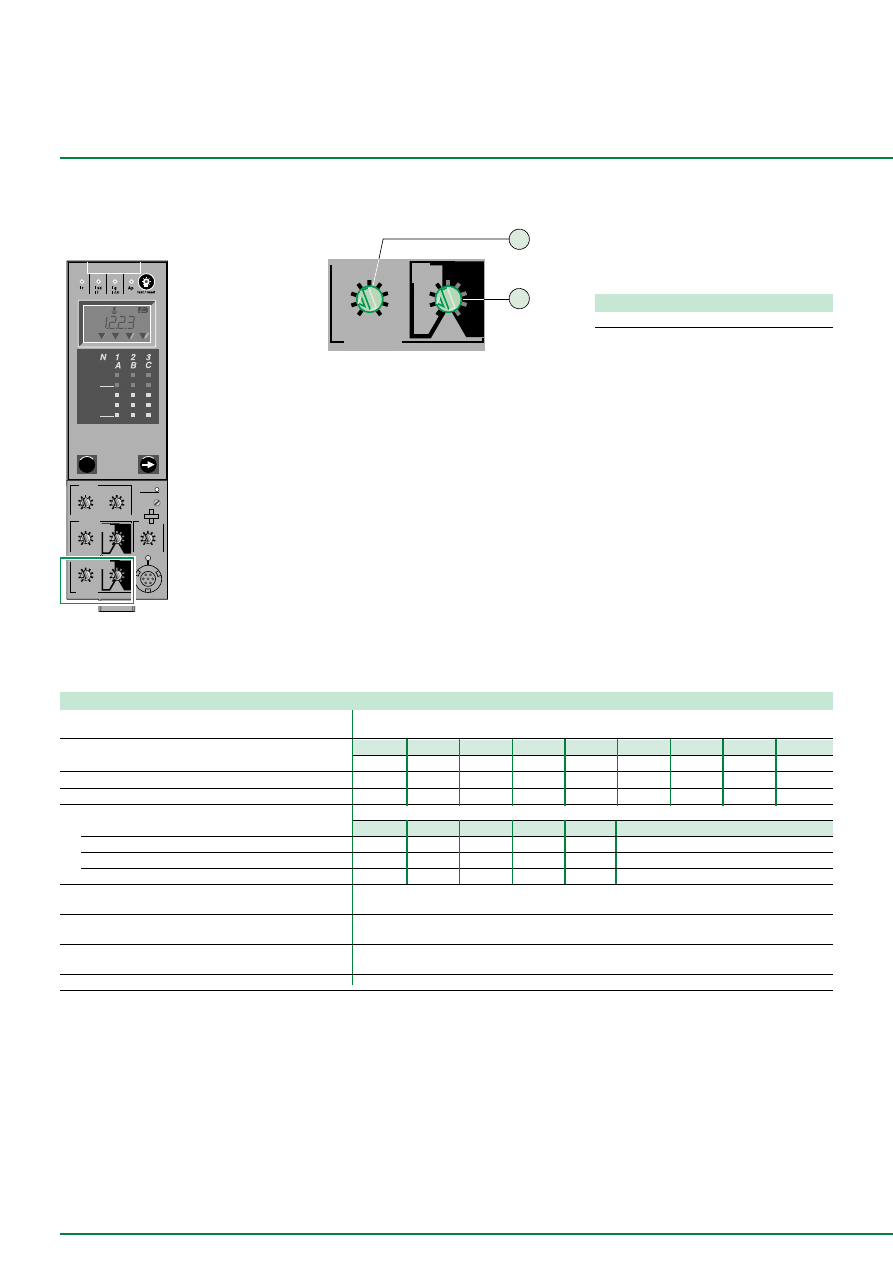
40
Micrologic 6.0 A
40
100 %
%
menu
.4
.5
.6
.7
.8
.9
.95
.98
1
delay
short time
I i
tsd
(s)
on
I
2
t
.
2
.
3
.
4
.
4
.
1
.
2
.
3
.
1
0
off
instantaneous
long time
alarm
Ir
x In
ground fault
B
C
D
E
F
G
H
J
Ig
tg
(s)
on
I
2
t
.
2
.
3
.
4
.
4
.
1
.
2
.
3
.
1
0
off
A
.5
1
2
4
8
12
16
20
tr
(s)
@ 6 Ir
24
setting
x Ir
2
2.5
3
4
5
6
8
10
Isd
1.5
x In
test
2
4
10
3
6 8
12
15
off
kA
s
Ir=
Ii=
tr=
Isd=
Ig=
tsd=
∆
t=
tg=
I
∆
n=
MAX
Additional technical information
Ground Fault Protection with Masterpact
NS630b/1600 and NS1600b/3200
Trip Units
Micrologic 6.0A
E68125
E68127
ground fault
B
C
D
E
F
G
H
J
Ig
tg
(s)
on
I
2
t
.
2
.
3
.
4
.
4
.
1
.
2
.
3
.
1
0
off
A
1
2
Technical data and Settings
The Micrologic 6.0 A/P/H trip units are
optionally equipped with Ground Fault
Protection. A ZSI terminal block allows
several control units to be linked to obtain
GFP total discrimination without time delay
tripping
Catalog Numbers
Micrologic 6.0A
33071
1 tripping threshold on a Ground fault.
2 time delay on a Ground fault and l
2
t on/off.
Functions
Micrologic 6.0A
“Ground Fault“ Protection of the “residual“ type
■
or the “source ground return“ type
Threshold setting
A
B
C
D
E
F
G
H
J
by switch
In
≤
400 A
Ig = In x …
0,3
0,3
0,4
0,5
0,6
0,7
0,8
0,9
1
accuracy : ±10 %
400 A < In < 1200 A Ig = In x …
0,2
0,3
0,4
0,5
0,6
0,7
0,8
0,9
1
In
≥
1200 A
Ig = …
500
640
720
800
880
960
1040
1120
1200
Time delay (th)
settings
with I2t ON
0
0,1
0,2
0,3
0,4
with I2t OFF
0,1
0,2
0,3
0,4
maximum overcurrent time without tripping (ms)
20
80
140
230
350
maximum breaking time (ms)
80
140
230
350
500
Indication of fault type (F) including Ground fault
■
by LED on the front panel
Fault indication contact including Ground fault
output by dry contact
■
Logic discrimination (Z)
by Ground T / W opto-electronic contact
■
External supply by AD module (1)
■
(1) This module is necessary to supply the indication (but not necessary to supply the protection).
Note :
■
With micrologic 6.0 P and H, each threshold over may be linked either to a tripping (protection) or to an indication, made by a programmable contact M2C or
optionnal M6C (alarm). The both actions, alarm and protection, are also available.
■
The ZSI cabling , identical for Masterpact NT/NW, Compact NS630b/1600 and Compact NS1600b/3200 is in details page 42
■
The external supply module AD and battery module BAT, identical for Masterpact NT/NW, Compact NS630b/1600 and Compact NS1600b/3200, are in details
page 42.
Setting by switch
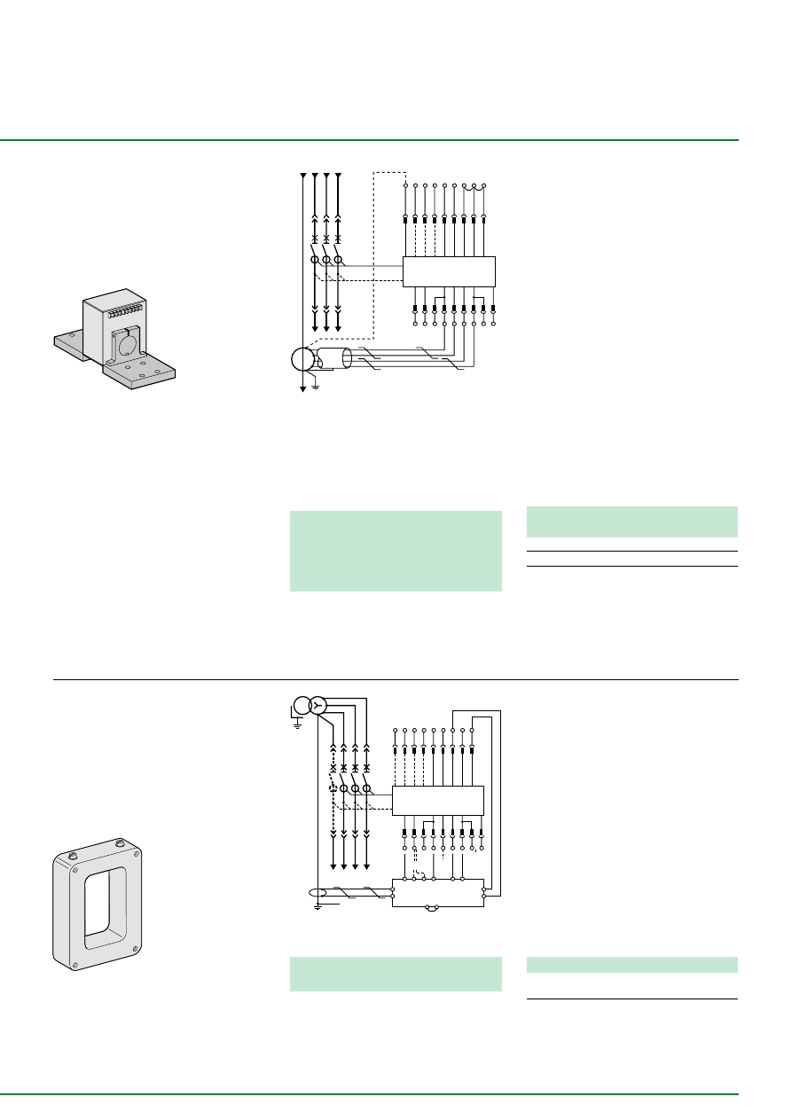
41
T4
T3
T2
T1
Micrologic 6
Z4
Z3
Z2
Z1
Z5
VN
V1
V2
V3
M3
M2
M1
F2+
F1
I
U
Q
10 11
7
6
5
12
8
9
1
3
13 14
MDGF module
X1
X2
PE
H1
H2
or
T4
T3
T2
T1
Micrologic 6
Z4
Z3
Z2
Z1
N
L3
L2
L1
Z5
VN
V1
V2
V3
M3
M2
M1
F2+
F1
Ñ
I
U
X2
VN
X1
SG2
SG1
Q
GND
H2
H1
External Transformer (CT)
for residual GF Protection
It is used with 3P circuit breakers and is
installed on the neutral conductor to
achieve a GFP protection of Residual type.
E47697
E68132
External transformer for
source ground return
(SGR) earth-fault protection
It is installed on the from LV transformer
starpoint to the ground link and is
connected to Micrologic 6.0 trip unit by
“MDGF summer” module to achieve the
Ground Fault Protection of SGR type..
Cabling Précautions:
■
Shielded cable with 2 twisted pairs
■
Shielding connected to GND on one end
only
■
Maximum length 5 meters
■
Cable cross-sectional area to 0.4 to
1.5 mm
2
■
Recommended cable: Belden 9552 or
equivalent.
■
The external CT rating may be compatible
with the circuit breaker normal rating:
NS630b to NS1600: TC 400/1600
NS1600b to NS2000: TC 400/2000
NS2500 to NS3200: TC 1000/4000
E68136
Catalog Numbers
ratings (A)
NS
400/2000
33576
1000/3200
34036
Cabling précautions:
■
Unshielded cable with 1 twisted pair
■
Shielding connected to GND on one end
only
■
Maximum length 150 meters
■
Cable cross-sectional area to 0.4 to
1.5 mm
2
■
Recommended cable: Belden 9552 or
equivalent.
E68137
Catalog Numbers
Current
Transformeteur SGR
33579
Wathever the Masterpact feeding type, by
open or bottom side, the power connection
and the terminal connection of external CT
are compulsary the same of those phases
CT ones.
Feeding by open side H2 is
connected to source side and H1 to
receiver side.
Feeding by bottom side H1 is
connected to source side and H2 to
receiver side.
H1 is connected to source side and
H2 to receiver side.
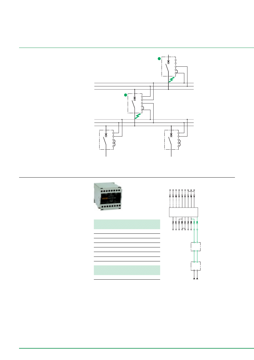
42
Z1
Z2
Z3
Z5
Z4
Z1
Z2
Z3
Z5
Z4
Z1
Z2
Z3
Z5
Z4
Z1
Z2
Z3
Z5
Z4
A
B
downstream
circuit breaker
fault 1
tsd = 0,3
upstream
circuit breaker
tsd = 0,2
fault 2
Zone selective interlocking
A pilot wire interconnects a number of
circuit breakers equipped with Micrologic A/
P/H control units, as illustrated in the
diagram above.
The control unit detecting a fault sends a
signal from downstream, the circuit breaker
remains closed for the full duration of its
tripping delay. If there is no signal from
downstream, the circuit breaker opens
immediately, whatever the tripping-delay
setting.
■
Fault 1:
only circuit breaker A detects the fault.
Because it receives no signal from
downstream, it immediately opens in spite
of its tripping delay set to 0.3.
■
Fault 2:
circuit breakers A and B detect the fault.
Circuit breaker A receives a signal from B
and remains closed for the full duration of its
tripping delay set to 0.3. Circuit breaker B
does not receive a signal from downstream
and opens immediately, in spite of its
tripping delay set to 0.2.
T4
T3
T2
T1
Micrologic 6.0
Z4
Z3
Z2
Z1
Z5
VN
V1
V2
V3
M3
M2
M1
F2+
F1
Ñ
BAT
module
H2
H1
H4
H3
G2
G1
L4
L3
110/2400 V AC
24/125 V DC
AD
module
Additional technical information
Ground Fault Protection with Compact CM
External power-supply
module
It makes possible to:
■
Use the display even if the circuit breaker
is open or not supplied.
■
Powers both the control unit and the M2C
and M6C programmable contacts .
■
With Micrologic A, display currents of
less than 20% of In.
■
With Micrologic P/H, display fault currents
after tripping and to time-stamp events
(alarms and trips).
■
Power supply :
110/130, 200/240, 380/415 V AC (+10% -
15%), consumption 10 VA
24/30, 48/60, 100/125 V DC (+20% -20%),
consumption 10 W.
■
Output voltage: 24 V DC, power
delivered: 5W/5VA.
■
Ripple < 5%
■
Classe 2 isolation.
■
A Battery module makes it possible to use
the display even if the power supply to the
Micrologic control unit is interrupted.
Cabing precautions
■
the cable length from the AD module to
the Trip Unit must not be longer than 10 m.
Catalog Numbers
External power-supply module
24/30 V DC
54440
48/60 V DC
54441
125 V DC
54442
110 V AC
54443
220 V AC
54444
380 V AC
54445
Catalog Numbers
Battery module
Module BAT 24 V DC
54446
025173
E68135
Note : the maximum length between two devices is
3000 m. The devices total number is 100 at the
maximum.
E68386En
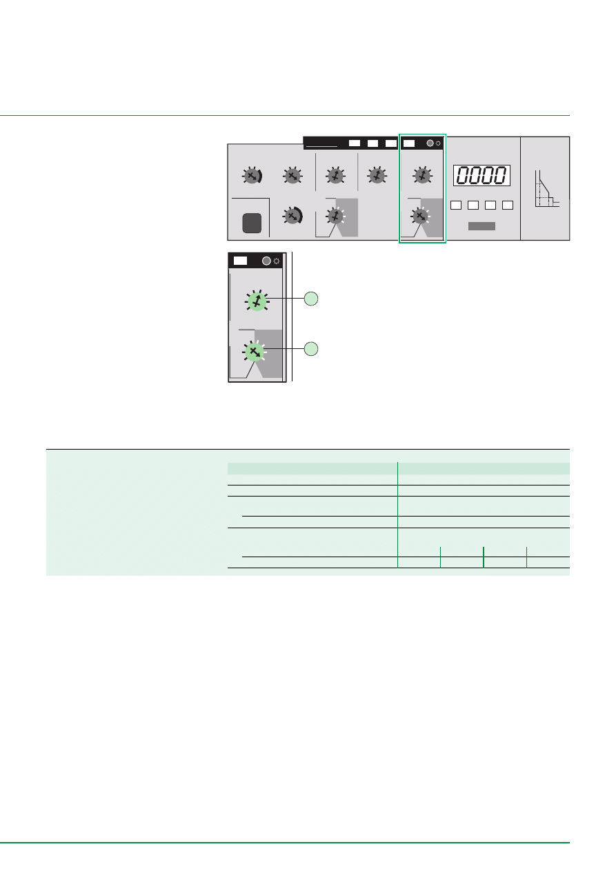
43
.5 .6
.7
.8
1
.4
.3
.2
Ig
x In
.4
.4
.3
.2
.1
.3
.2
.1
o n
I
2
t
o ff
tg
(s)
>
Ig
2
1
Technical data and Settings
STR53UE trip unit
The STR53UE trip unit is optionally equipped
with Ground Fault Protection
(1)
. This can be
completed by the ZSI “Logic discrimination”
option.
E56662
> Ih
> Im
> Ir
µ
P
fault
test
STR 53 UE
Io
x In
-
test
+
8 16
16
4
2
1
(s) @ 6 Ir
.3
.3
.2
.1
0
.2
.1
0
o n
I
2
t
o ff
.9 .93
.95
.98
1
.88
.85
.8
.8 .9
1
.7
.6
.5
1
4 5
6
8
10
3
2
1.5
4 6
8
10
11
3
2
1.5
.5 .6
.7
.8
1
.4
.3
.2
x Io
Ir
Isd
x Ir
Ii
x In
Ig
x In
tr
tsd
(s)
.4
.4
.3
.2
.1
.3
.2
.1
o n
I
2
t
o ff
tg
(s)
%Ir
>
Ir
>
Isd
>
Ig
A
In
I1
I2
I3
Isd
Ir
li
tr
tsd
E56662
1 tripping threshold on Ground fault.
2 time delay on Ground fault and l
2
t on/off.
(1) For Compact NS 100 to 630 A, Ground Fault
Protection can be achieved in Zero Sequence up to
30 A by addition of a Vigi module.
Functions for Compact NS4400/630
STR53UE
“Ground Fault“ protection (T)
■
Type
residual current
Tripping threshold
Ig
adjustable (8 indexes) - 0.2 to 1 x In
accuracy
± 15 %
Tripping time
maximum overcurrent time
adjustable (4 indexes + function “I
2
t = cte”)
without tripping
60
140
230
350
total breaking time
£
140
£
230
£
350
£
500
Technical data of Ground
Fault Protection for
Compact C and Compact NS
E56663
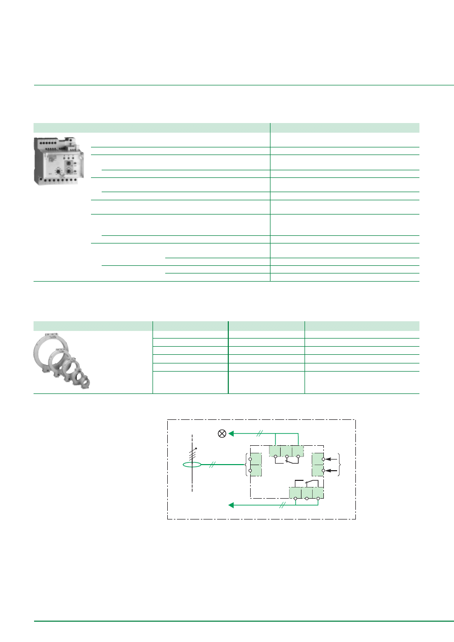
44
Ground Fault Protection with the RH relays
and toroids of the A, OA and E types
Technical data and settings
RH328AP
Toroids
044322
Functions
RH328AP relays
Sensitivity I
D
n
number of thresholds
32: from 30 mA to 250 A, setting with 2 selectors
Time delay (ms)
0, 50, 90, 140, 250, 350, 500, 1s.
Early warning
sensitivity
automatically set at In
D
/2
time delay
200 ms
Device test
local
electronic + indicator light + contact
permanent
toroid/relay connection
Resetting
local and remote by breaking the auxiliary power
supply
Local indication
insulation fault and toroid link breaking
by indicator light with latching mechanism
by indicator light
early warning
by indicator light without latching mechanism
Output contact
fault contact
number
1 standard
type of contact: changeover switches
with or without latching mechanism
early warning contact number
1 with “failsafe” safety
type of contact: changeover switches
without latching mechanism
Toroids
Type A
Æ
Æ
Æ
Æ
Æ
(mm)
Type OA
Æ
Æ
Æ
Æ
Æ
(mm)
Type E
Æ
Æ
Æ
Æ
Æ
(mm)
Dimensions
TA
30
POA
46
TE30
30 (all thresholds)
PA
50
GOA
110
PE50
50 (all thresholds)
IA
80
IE80
80 (threshold
³
300 mA)
MA
120
ME120
120 (threshold
³
300 mA)
SA
200
SE200
200 (threshold
³
300 mA)
GA
300
The protection provided is of the Zero sequence or Source Ground Return type. The RH
relay acts on the MX or MN coil of the protection circuit-breaker.
042596
Cabling the Ground Fault
Protection by Vigirex
Ground Fault Protection by Vigirex and
associated Toroid controls the breaking
device tripping coil: circuit-breaker or
switch controlled.
10
11
9
MN
6
5
8
7
aa
RH328A
13
14
12
early warning
indicator light
E58767En
Vigirex cabling diagram

45
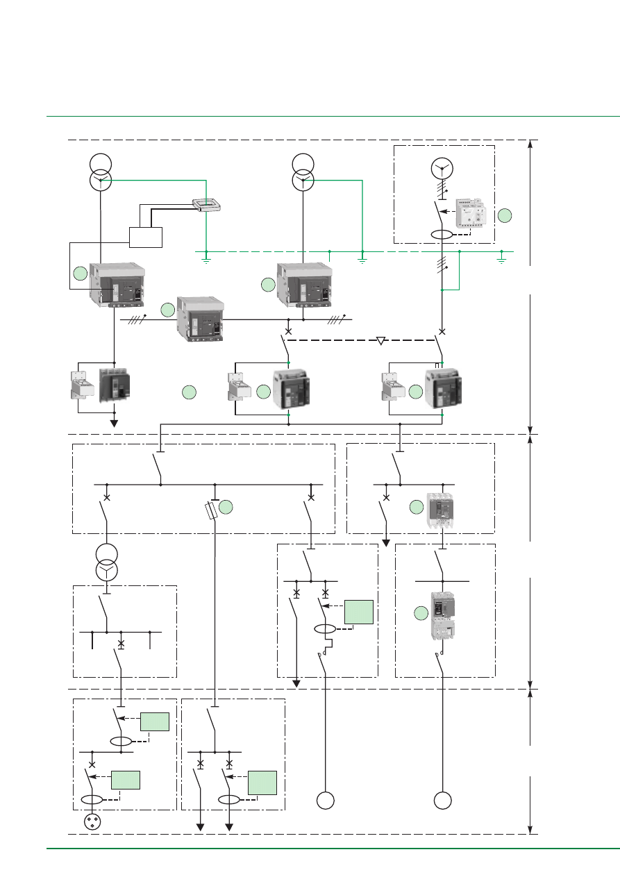
46
Additional technical information
Implementation in the installation
E68144En
Diagram of a standard electrical installation showing most of the cases encountered in real life
1
2
8
1b
4
6
6b
7
1000 kVA
2000 kVA
2000 kVA
main LV board
subdistribution
boards
loads
Level B
Level A
Level C
sensitive
motors
distant
motors
Vigirex
RH328 AP
Toroid A
300 mm
Masterpact
M20NI 3P
Compact
NS100
D25
Compact
NS160 3P
+ Vigi
module
ZS
3 A
100 ms
Compact
NS400 4P
T option
1000 A
to
> 4000 A
100 A
to
2000 A
RCD
30 mA
RCD
300 mA
ZS
3 A
100 ms
decoupling
transformer
< 100 A
gI 100
T1 T2
T1 T2
Masterpact NW20
4P
Micrologic 6.0P
Masterpact NW20
4P
Micrologic 6.0P
Masterpact NT12
3P
Micrologic 6.0A
Masterpact NT12
3P
Micrologic
3
Compact NS800
4P
Micrologic 6.0A
1
3
MGDF
H1
H2
7
H2
H1
H2
H1
5
H2
H1
M
M
1.5
2
3
4
5
6
8
10
xIr
Im
.63
.7
.8
.85
.9
.95
.98
1
xIn
Ir
STR 22 SE
90
105
%Ir
alarm
Im
Ir
I n = 2 5 0 A
250
P93083
OFF
MERLIN GERIN
compact
NS250 N
Ui 750V. Uimp 8kV.
220/240
380/415
440
500
660/690
250
85
36
35
30
8
50
cat A
IEC947-2
UTE VDE BS CE
I UNE NEMA
Ue
(V)
Icu
(kA)
Ics=100% Icu
160/250A
push
to
trip
push
to
trip
before di•lectric
test
remove this c
over
vigi
A100NHL
A250NHL
100/520V-50/6
0Hz
2 4 6
5
-2
HS 0,03(
∆
t=0)
310
0
60
150
∆
t(ms)
3
0,3
1
10
I
∆
n(A)
test
reset
7
8
9
10 11 12 13 14
7
8
9
10 11 12 13 14
1
1
2 3 4 5 6
2 3 4 5 6
on
140
inst.
500
250
1s
50
90
350
mS
MERLIN GERIN
vigirex
RH328A
50652
A
0,1
0,03
0,2
0,125
0,25
0,05
0,075
0,15
x1
x0,1
x10
x100
Ic
µ
P
>Ir
>Im
test
fault
STR 53 UE
60
75
90
105 %Ir
I
Im
Ir
Io
tr
tm
(s)
x In
x Ir
x Io
x In
on I
2
t off
(s) at 1.5 Ir
test
R
tr
tm
Im
Ir
I
MERLIN GERIN
compact
NS400 H
Ui 750V.
Uimp 8kV.
Ue
(V)
220/240
380/415
440
500/525
660/690
100
70
65
40
35
IEC 947-2
UTE VDE BS CEI
UNE NEMA
Icu
(kA)
cat B
Ics = 100% Icu
Icw 6kA / 0,25s
In = 400A
.8
1
.63
.5
.9
.93
.95
.98
.88
.85
.8
1
4
5
6
8
3
2
1.5
10
4
6
8
10
3
2
1.5
12
.3
.3
.2
.1
.2
.1
0
0
120
240
60
30
15
240
.9
.93
.95
.98
.88
.85
.8
1
push
to
trip
push
to
trip
400
Reset
reset
Ap
Ig
I
∆
n
Isd
I i
Ir
Micrologic 70
Ics = 100% Icu
220/440
525
690
100
100
85
Icw 85kA/1s
NX 32 H 2
cat.B
IEC 947-2
UTE VDE BS CEI UNE AS NEMA
EN 60947-2
50/60Hz
Ue
Icu
(V)
(kA)
0 1 2 5 3
push OFF
push ON
O OFF
discharged
Reset
reset
Ap
Ig
I
∆
n
Isd
I i
Ir
Micrologic 70
Ics = 100% Icu
220/440
525
690
100
100
85
Icw 85kA/1s
NX 32 H 2
cat.B
IEC 947-2
UTE VDE BS CEI UNE AS NEMA
EN 60947-2
50/60Hz
Ue
Icu
(V)
(kA)
0 1 2 5 3
push OFF
push ON
O OFF
discharged
Reset
reset
Ap
Ig
I
∆
n
Isd
I i
Ir
Micrologic 70
Ics = 100% Icu
220/440
525
690
100
100
85
Icw 85kA/1s
NX 32 H 2
cat.B
IEC 947-2
UTE VDE BS CEI UNE AS NEMA
EN 60947-2
50/60Hz
Ue
Icu
(V)
(kA)
0 1 2 5 3
push OFF
push ON
O OFF
discharged
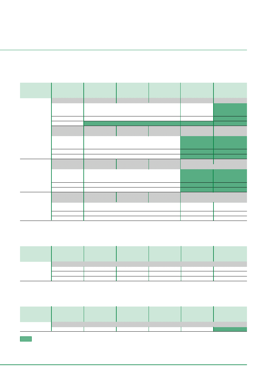
47
Table summarising the GFP functions
of the Merlin Gerin ranges
Standard GFP option
Type of GFP
Technical data
Masterpact
Compact NS
Compact NS
Compact NS
Compact NS
current
NT 630 to 1600 A
1600b to 3200 A
630b to 1600 A
400 to 630 A
100 to 250 A
range
NW 800 to 6300 A
Residual sensing
4P4D circuit breaker + Micrologic 6.0 A/P/H Micrologic 6.0 A
Micrologic 6.0 A
STR53UE option T no
current limit
1200 A (max.*)
from 0,2 In to In
(* lower limit according
± 10 %
to the rating)
time delay
Inst to 0,4 s (I
2
t On or Off)
Inst. to 0,3 s
TCE
injustified
injustified
3P3D, 4P3D
Micrologic 6.0 A/P/H Micrologic 6.0 A
Micrologic 6.0 A
no
no
circuit breaker +
current limit
1200 A (max.*)
(* lower limit according
± 10 %
to the rating)
time delay
Inst to 0,4 s (I
2
t On ou Off)
TCE
(1)
yes
(2)
Source Ground
4P4D, 3P3D, 4P3D Micrologic 6.0 A/P/H Micrologic 6.0 A
Micrologic 6.0 A
no
no
Return
circuit breaker +
only by external relay (Vigirex)
current limit
1200 A
(* lower limit according
± 10 %
to the rating)
time delay
Inst to 0,4 s (I
2
t On ou Off)
TCW
(3)
+ MDGF
yes
Zero Sequence
4P4D, 3P3D, 4P3D Micrologic 7.0 A/P/H Micrologic 7.0 A
Micrologic 7.0 A
only 4P4D+ internal Vigi or external
circuit breaker +
relay Vigirex
current limit
0,5 to 30 A
300 mA to 30 A
30 mA to 3 A
+0-20 %
time delay
600 to 800 ms
Inst. to 0,3 s
Inst. to 0,3 s
TCE
external
Internal
Internal
Option with Vigirex external relay
Type of GFP
Technical data
Masterpact
Compact NS
Compact NS
Compact NS
Compact NS
current
NT 630 to 1600 A
1600 to 3200 A
630 to 1600 A
400 to 630 A
100 to 250 A
range
NW 800 to 6300 A
Source Ground
3P3D, 4P3D, 4P4D circuit breaker + Vigirex relay + external
Return or
current limit
30 mA to 250 A
30 mA to 250 A
30 mA to 250 A
30 mA to 250 A
30 mA to 250 A
Zero Sequence
time delay
Inst to 1 s
Inst to 1 s
Inst to 1 s
Inst to 1 s
Inst to 1 s
toroids 30 to 300 mm yes
yes
yes
yes
yes
Option ZSI
Type of GFP
Technical data
Masterpact
Compact NS
Compact NS
Compact NS
Compact NS
current
NT 630 to 1600 A
1600 to 3200 A
630 to 1600 A
400 to630 A
100 to 250 A
range
NW 800 to 6300 A
ZSI
3P3D, 4P3D, 4P4D circuit breaker
by pilot wire
yes
yes
yes
yes
no
not feasible or injustified
(1) If distributed Neutral conductor.
(2) TCE of the same rating as those installed in the circuit-breaker. To be positioned and connected with accuracy.
(3) TCW se connecte au Micrologic 6.0A/P/H/ par l’intermédiaire d’un boîtier MDGF summer.
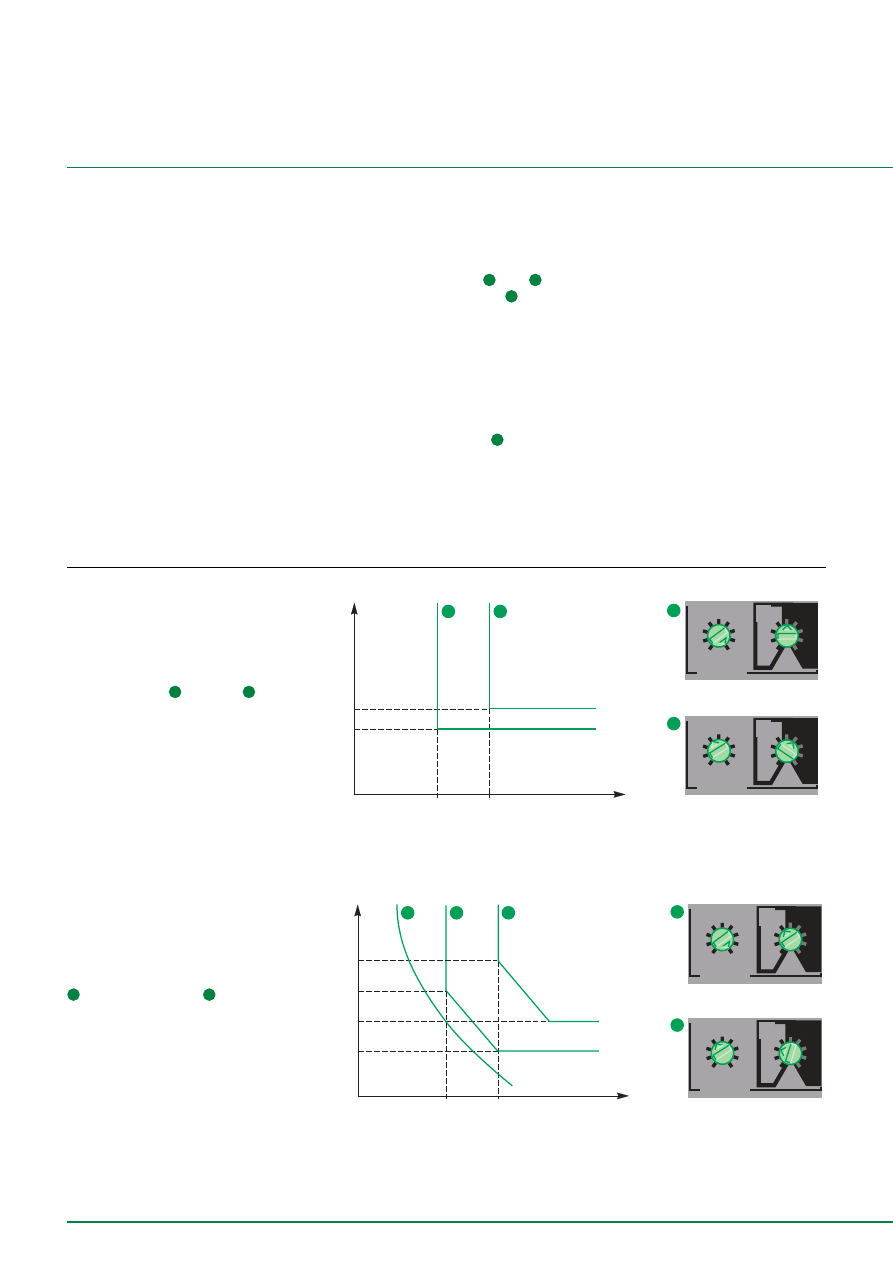
48
Ih
T(s)
2
4
4
2
ground fault
B
C
D
E
F
G
H
J
Ig
tg
(s)
on
I
2
t
.
2
.
3
.
4
.
4
.
1
.
2
.
3
.
1
0
off
A
ground fault
B
C
D
E
F
G
H
J
Ig
tg
(s)
on
I
2
t
.
2
.
3
.
4
.
4
.
1
.
2
.
3
.
1
0
off
A
0,3
0,4
800 A
1200 A
0,4 s
0,5 s
Micrologic 6.0A
Micrologic 6.0P
Additional technical information
Study of discrimination between GFP
The diagram on page 10 shows an
industrial or tertiary LV electrical installation.
The co-ordination rules must be
implemented to guarantee safety and
continuity of supply during operation.
Incoming circuit-breakers
1
and
2
,
and coupling circuit-breaker
1
b
■
the incoming circuit-breakers are four-
pole:
❏
this is compulsory
(1)
as both sources
are grounded (Multisources / Multiple
Groundings). Four-pole breaking eliminates
circulation of natural currents via the PE
conductor, thus easily guaranteeing a
Ground Fault Protection free of
malfunctions.
❏
the coupling circuit-breaker
1
b can be
three-pole or four-pole
(1)
.
(1)
if the diagram only had one grounding (e.g. at
coupling level), the incoming and coupling circuit-
breakers would have to be three-pole.
Discrimination of Ground Fault
Protection
■
in normal operation N,
the discrimination rules between the
incoming and outgoing circuit-breakers
must be complied with for each source
(S1 or S2),
■
in Replacement R1 or R2 operation:
❏
these must be applied to all the supplied
outgoers (S1 and S2),
❏
coupling can be equipped with a Ground
Fault Protection function to improve
discrimination (case of a fault on the
busbar). This Protection must be selective
both upstream and downstream. This is
easily implemented if the ZSI function is
activated,
■
switch or coupling circuit-breaker: when
the Ground Fault Protection function is
installed on the coupling, it may be provided
by a circuit-breaker identical to the source
protection devices. This ensures immediate
availability on site of a spare part should
one of the incoming circuit-breakers
present an anomaly.
Time discrimination of the
Ground Fault Protections
Implementation Examples
Example 1:
The time discrimination rules applied to
Masterpact MW32
2
and NT12
4
result in
the settings described in the figure below.
The indicated setting allows total
discrimination between the 2 circuit-
breakers.
Note: the time delay can be large at this
level of the installation as the Busbars are
sized for time discrimination.
E68145
Example 1a: optimised setting
Discrimination can be optimised by the
implementation of the function “l²t on”.
If we return to example 1, in event of a
ground fault, discrimination between NT12
4
and the gl 100 A fuse
6
b is total.
Note: Ground Fault Protection is similar to a
Phase/Neutral short-circuit protection.
E68146
Ih
T(s)
2
4
4
2
6b
ground fault
B
C
D
E
F
G
H
J
Ig
tg
(s)
on
I
2
t
.
2
.
3
.
4
.
4
.
1
.
2
.
3
.
1
0
off
A
ground fault
B
C
D
E
F
G
H
J
Ig
tg
(s)
on
I
2
t
.
2
.
3
.
4
.
4
.
1
.
2
.
3
.
1
0
off
A
0,3
0,4
800 A
1200 A
0,4 s
0,5 s
Micrologic 6.0A
Micrologic 6.0A
1,5 s
2 s
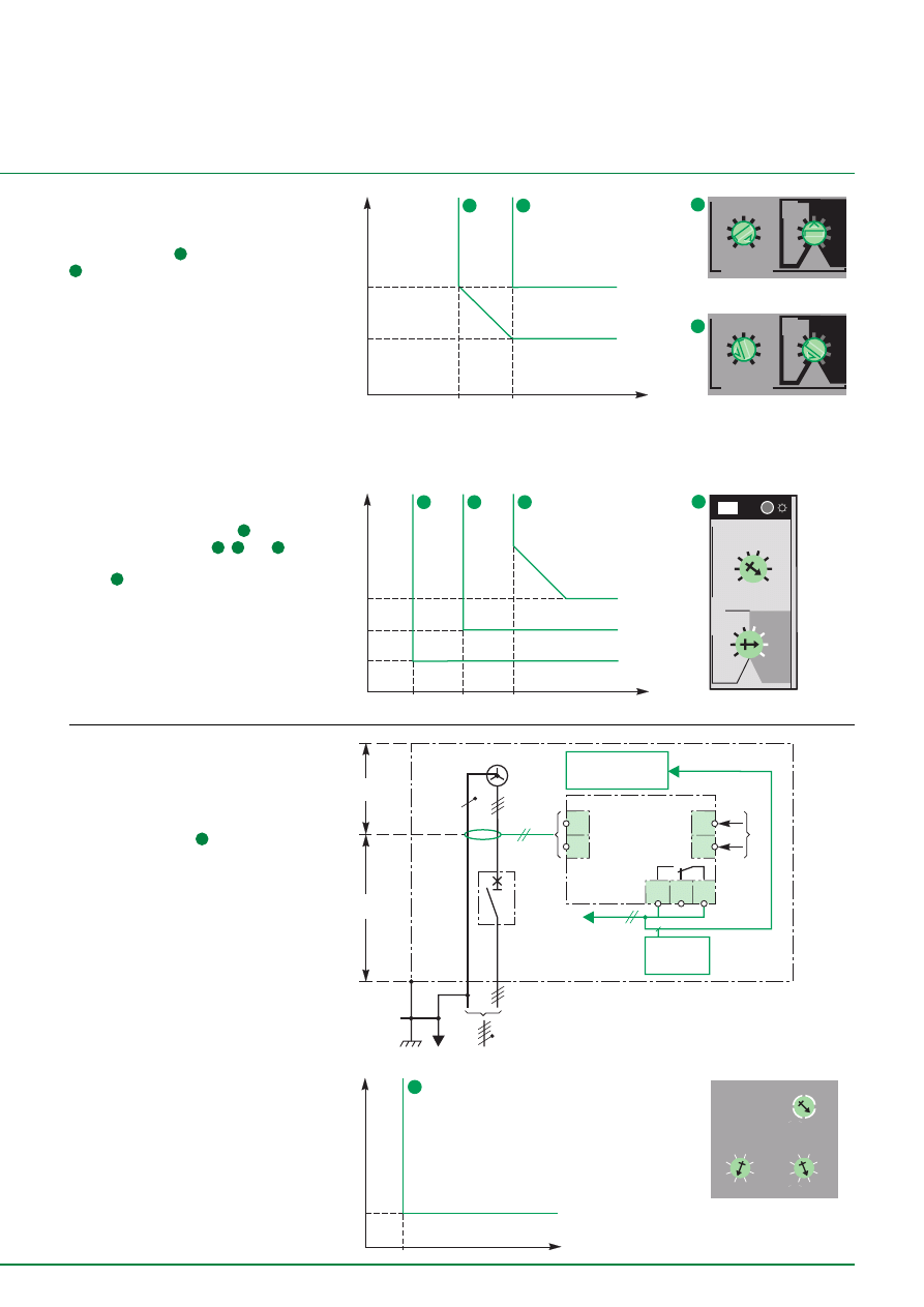
49
10
11
9
MN
6
5
8
7
GE
3 Ph + N
PE
PE
aa
RH328A
GE
uncoupling
control
ON/OFF control GE
protected
area
unprotected
area
Ih
T(s)
1
3
3
1
ground fault
B
C
D
E
F
G
H
J
Ig
tg
(s)
on
I
2
t
.
2
.
3
.
4
.
4
.
1
.
2
.
3
.
1
0
off
A
ground fault
B
C
D
E
F
G
H
J
Ig
tg
(s)
on
I
2
t
.
2
.
3
.
4
.
4
.
1
.
2
.
3
.
1
0
off
A
0,1
0,4
240 A
Micrologic 6.0P
Micrologic 6.0A
0,5 s
0,2 s
1200 A
Implementation examples
Example 2:
The discrimination rules applied to
Masterpact MW32
1
and Compact NS800
3
result in the settings described in the
figure below. The indicated setting allows
total discrimination between the 2 circuit-
breakers.
Note: time discrimination upstream does not
present problems. On the other hand,
downstream time discrimination is only
possible with short-circuit protection
devices with a rating
£
than 40 A.
Use of the “l²t on” function improves this limit
for the gl fuses placed downstream (see
example 1a).
E68147
I(A)
T(s)
2
Inst
250 A
Special use of Ground Fault
Protection
Generator protection
■
■
■
■
■
The principle
The Vigirex RH328 AP
9
is installed as
generator protection. The principle of this
protection is as follows:
❏
tripping in event of a ground fault
upstream (protected area),
❏
non tripping in event of a ground fault
downstream (unprotected area),
■
■
■
■
■
The constraints
The protection functions must:
❏
be very fast to avoid deterioration of the
generator (and must control stopping and
placing out of operation of the GE),
❏
be very fast to maintain continuity of
supply (and must control the coupling
device of the GE). This function is important
in event of parallel-connected generators,
❏
have an average tripping threshold:
normally from 30 A to 250 A. On the other
hand, discrimination with the Ground Fault
Protections of the installation is “naturally”
provided (no effect on the “unprotected
area”),
■
■
■
■
■
Setting of the protection device
Due to the above constraints, setting can
be:
❏
threshold l
D
n: from 30 A to 250 A,
❏
time delay: instantaneous.
E58693En
Example 1b: optimised discrimination
Going back to example 1, on a fault
downstream of circuit-breaker
7
, the
Ground Fault Protections
4
,
6
and
7
are
in series. Installation of a Vigicompact
NS160
7
allows total discrimination of the
Ground Fault Protections as standards
whatever the setting lr of the Vigicompact
NS 160.
Note: although thresholds may be very
different (lg = 400 A for NS400, lg = 30 A
for NS160), it is necessary to comply with
time delay rules between protection
devices (index 0.2 for NS400, index 0.1 for
NS160).
E58696
mS
90
140 250
350
500
1000
inst
50
75
100 125
15
200
250
30
50
mA
x1000
x1
x100
x10
RH328AP
E58694
6
6
.5 .6
.7
.8
1
.4
.3
.2
Ig
x In
.4
.4
.3
.2
.1
.3
.2
.1
o n
I
2
t
o ff
tg
(s)
>
Ig
Ih
T(s)
6
4
7
0,1
0,2
400 A
800 A
0,1 s
0,2 s
0,3 s
0,3
30 A
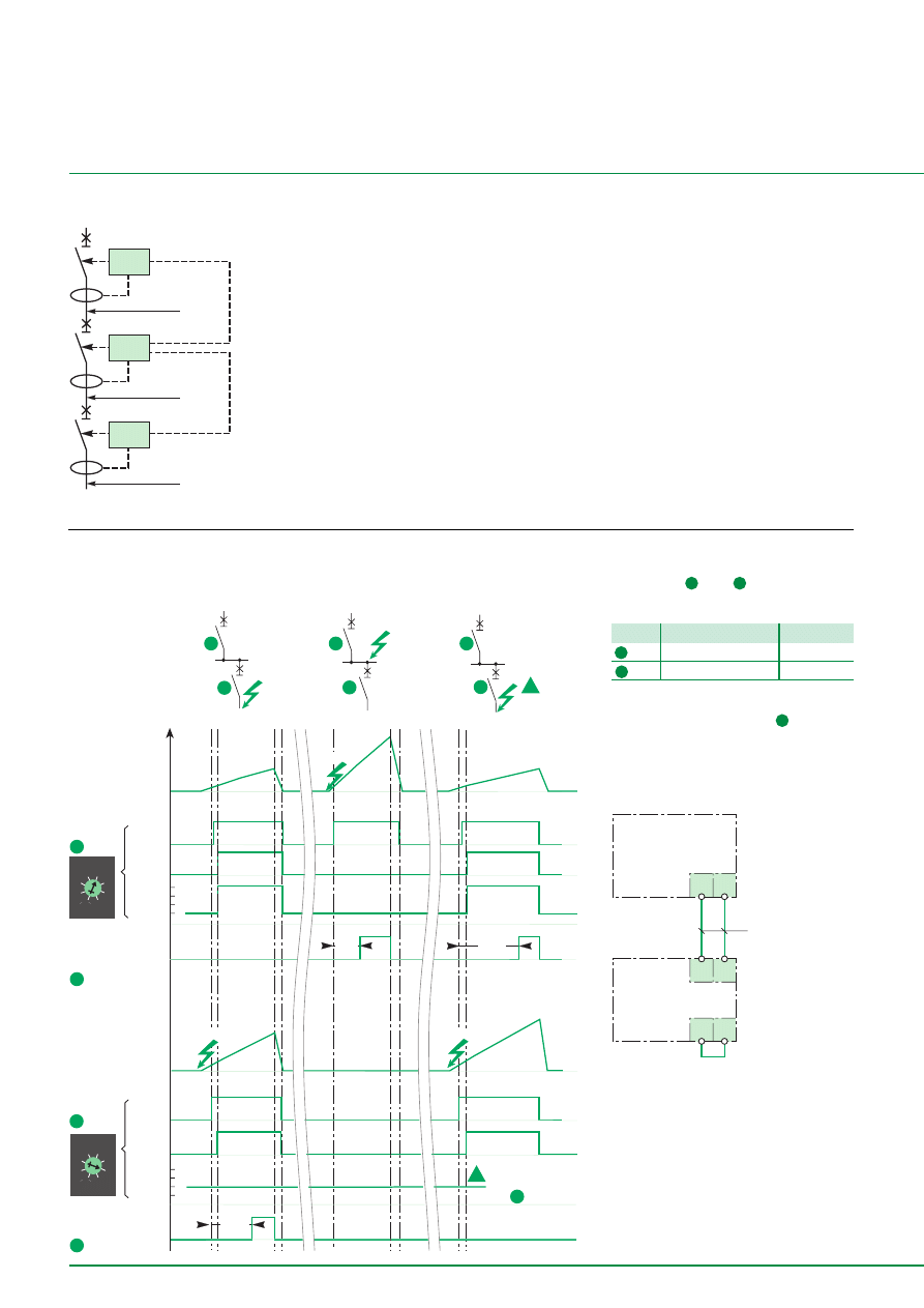
50
relay 2
800 A
point A
point C
point B
relay 3
300 A
circuit-breaker D1
circuit-breaker D3
circuit-breaker D2
relay 1
1200 A
Z21 Z22
Z11 Z12
D2
Z11 Z12
D1
bridged
if no ZSI
downstream
pilot wire
(twisted)
Additional technical information
Study of ZSI discrimination
Principle
This type of discrimination can be achieved
with circuit-breakers equipped with
electronic control units designed for this
purpose (Compact, Masterpact): only the
Short Delay Protection (SD) or Ground Fault
Protection (GFP) functions of the controlled
devices are managed by Logic Discrimi-
nation. In particular, the Instantaneous
Protection function - intrinsic protection
function - is not concerned.
Settings of the controlled circuit-
breakers
■
time delay: the staging rules of the time
delays of time discrimination must be
applied,
■
thresholds: there are no threshold rules
to be applied, but it is necessary to respect
the natural staging of the ratings of the
protection devices (lcrD1
³
lcrD2
³
lcrD3).
Note: this technique ensures discrimination
even with circuit-breakers of similar ratings.
E51141
Principle
The Logic Discrimination function is
activated by transmission of information on
the pilot wire:
■
ZSI input:
❏
low level (no faults downstream): the
protection function is on standby with a
reduced time delay (
£
0.1 s),
❏
high level (presence of faults
downstream): the Protection function in
question moves to the time delay status set
on the device,
■
ZSI output:
❏
low level: the circuit-breaker does not
detect any faults and sends no orders,
❏
high level: the circuit-breaker detects a
fault and sends an order.
E58697
Operation
Chronogram
The analysis is conducted based on
the diagram on page 46 showing the 2
Masterpacts
2
and
4
b.
Masterpact settings
time delay
threshold
4
index .4
< 1200 A
4
b
index .2
< 1200 A
(1)
(1) complying with the rules stated above.
The downstream Masterpact
4
b also has
input ZSI shunted (ZSI input at “1”) ;
consequently it keeps the time delay set in
local (index .2) in order to guarantee time
discrimination to the circuit-breakers placed
downstream.
E58684
Operation
The pilot wire connects the Masterpact in
cascade form. The attached chronogram
shows implementation of the ZSI
discrimination between the 2 circuit-
breakers.
4
3
2
1
4
3
2
1
1
2
3
4b
2
0,2 s
!
0,4 s
0,1s
th
on
I
2
t
off
.3
.4 .4
.3
.2
.1
.1
.2
2
4b
4b
2
2
2
4b
4b
4b
!
th
on
I
2
t
off
.3
.4 .4
.3
.2
.1
.1
.2
A
B
A
B
A
B
fault
on 4b
time
delay
ZSI
output
downstream
circuit-breaker
setting
measu-
rement
fault
current
in B
measu-
rement
time
delay
upstream
circuit-breaker
setting
ZSI
input
upstream
circuit-breaker
tripping
fault
current
in A
downstream
circuit-breaker
tripping
fault B
tripping
fault
on
fault A
fault A
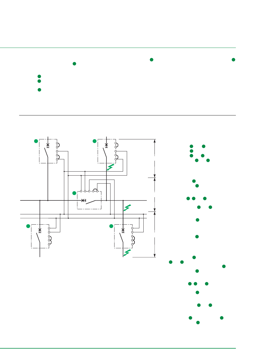
51
out
Z1
Z2
Z3
Z5
Z4
in
out
Z1
Z2
Z3
Z5
Z4
in
Z1 Z2 Z3
Z5
Z4
tsd = cran 0,3
tsd = cran 0,2
out
in
out
Z1
Z2
Z3
Z5
Z4
in
out
Z1
Z2
Z3
Z5
Z4
in
tsd = cran 0,1
A
B
C
2
1
1a
3
4
tsd = cran 0,3
incomer
coupling
outgoer
Multisource diagram with ZSI
function
Analysis of operation
The Masterpacts are connected according
to their position in the installation:
■
Masterpact
1
and
2
: index .4,
■
Masterpact
1
a : index .3,
■
Masterpact
3
and
4
: index .2.
The Masterpacts
3
and
4
haves their ZSI
input shunted (ZSI input at the high level).
■
■
■
■
■
Normal N operation
An insulation fault occurs downstream of
the Masterpact
4
.
❏
the Masterpact
4
:
- detects the fault,
- sends a message to the upstream of the
Masterpact
1
,
2
and
1
a ,
- does not receive any information,
❏
the Masterpacts
2
and
1
a receive the
information but do not detect the fault; they
are not concerned,
❏
the Masterpact
1
receives the
information and detects the fault: it moves
to the standby position with a time delay at
index 0.4,
❏
the Masterpact
4
eliminates the fault
after the time delay index .2 and the system
returns to its normal status.
■
■
■
■
■
Replacement R2 operation
the Masterpact
2
is open, the Masterpacts
1
and
1
a are closed; an insulation fault
occurs downstream of Masterpact
4
:
❏
the Masterpact
4
:
- detects the fault,
- sends a message to the upstream to
Masterpacts
1
,
2
and
1
a,
- does not receive any information,
❏
the Masterpact
2
receives the
information but is not in operation; it is not
concerned,
❏
the Masterpacts
1
and
1
a receive the
information and “see” the fault; they move
to the standby position with a time delay at
index 0.4 for
1
and index 0.3 for
1
a,
❏
the Masterpact
4
eliminates the fault
after the time delay 0.1 and the system
returns to its normal status.
E68133
Pilot wire installation precautions
■
length: 300 m,
■
conductor type: twisted,
■
number of devices:
❏
3 upstream devices,
❏
10 downstream devices.
■
■
■
■
■
case 1
When a fault occurs in A, the 2 circuit-
breakers detect it. The Masterpact
4
sends an order (ZSI output moves to the
high level) to the ZSI input of the
Masterpact
2
. The time delay of
Masterpact
2
moves to its natural time
delay index .4.
Masterpact
4
trips after its time delay
(index .2) and eliminates the fault.
■
■
■
■
■
case 2
The fault is located in B. Masterpact
2
receives no ZSI information (input at low
level). It detects the fault and eliminates it
after its ZSI mini time delay of 0.1s.
The constraints on the busbar are
considerably fewer than for implementation
of conventional time discrimination.
■
■
■
■
■
case 3
In event of an anomaly on circuit-breaker
4
,
protection is provided by the upstream
Masterpact:
❏
in 0.1 s if the downstream circuit-breaker
has not detected the fault,
❏
at the natural time delay of the upstream
Masterpact (0.4 s for our example) if there
is an anomaly of the downstream circuit-
breaker (the most unfavourable case)

52
Notes

DBTP140GUI/EN
© 2000 Schneider Electric - All rights reserved
As standards, specifications and designs develop from time to time, always ask for
confirmation of the information given in this publication.
Published by: Schneider Electric
Designed by: AMEG
Printed by:
Schneider Electric Industries SA
5, rue Nadar
92506 Rueil Malmaison - Cedex France
Tel : +33 (0)1 41 29 82 00
Fax : +33 (0)1 47 51 80 20
http://www.schneiderelectric.com
This document has been printed on ecological paper.
DBTP140GUI/EN
07/00
Document Outline
- GROUND FAULT PROTECTION
- CONTENTS
- THE ROLE OF “GROUND FAULT PROTECTION”
- THE GFP TECHNIQUE
- GFP IMPLEMENTATION
- CONCLUSION
- INSTALLATION AND IMPLEMENTATION OF GFP SOLUTIONS
- ADDITIONAL TECHNICAL INFORMATIONS
- Ground Fault Protection with Masterpact NT/NW
- Ground Fault Protection with Masterpact NS630b/1600 and NS1600b/3200
- Ground Fault Protection with Compact CM
- Ground Fault Protection with the RH relays and toroids of the A, OA and E types
- Implementation in the installation
- Study of discrimination between GFP
- Study of ZSI discrimination
Wyszukiwarka
Podobne podstrony:
2008 06 Continuous Data Protection
Uwagi do dokumentu Agencji Praw Podstawowych Unii Europejskiej Protection against discrimination on
Marisa Chenery Roxie s Protectors 06 Dirk s Love
MT st w 06
Kosci, kregoslup 28[1][1][1] 10 06 dla studentow
06 Kwestia potencjalności Aid 6191 ppt
06 Podstawy syntezy polimerówid 6357 ppt
06
06 Psych zaburz z somatoformiczne i dysocjacyjne
GbpUsd analysis for July 06 Part 1
Probl inter i kard 06'03
06 K6Z4
06 pamięć proceduralna schematy, skrypty, ramyid 6150 ppt
Sys Inf 03 Manning w 06
więcej podobnych podstron